WO2020250412A1 - 画像処理装置及び画像処理方法 - Google Patents
画像処理装置及び画像処理方法 Download PDFInfo
- Publication number
- WO2020250412A1 WO2020250412A1 PCT/JP2019/023632 JP2019023632W WO2020250412A1 WO 2020250412 A1 WO2020250412 A1 WO 2020250412A1 JP 2019023632 W JP2019023632 W JP 2019023632W WO 2020250412 A1 WO2020250412 A1 WO 2020250412A1
- Authority
- WO
- WIPO (PCT)
- Prior art keywords
- image
- input image
- value
- weight
- unit
- Prior art date
- Legal status (The legal status is an assumption and is not a legal conclusion. Google has not performed a legal analysis and makes no representation as to the accuracy of the status listed.)
- Ceased
Links
Images


Classifications
-
- G—PHYSICS
- G06—COMPUTING OR CALCULATING; COUNTING
- G06T—IMAGE DATA PROCESSING OR GENERATION, IN GENERAL
- G06T5/00—Image enhancement or restoration
- G06T5/70—Denoising; Smoothing
-
- H—ELECTRICITY
- H04—ELECTRIC COMMUNICATION TECHNIQUE
- H04N—PICTORIAL COMMUNICATION, e.g. TELEVISION
- H04N1/00—Scanning, transmission or reproduction of documents or the like, e.g. facsimile transmission; Details thereof
- H04N1/387—Composing, repositioning or otherwise geometrically modifying originals
Definitions
- the present invention relates to an image processing apparatus and an image processing method.
- a conventional image processing apparatus is based on an image updating means that performs image updating processing using a captured image and a point image intensity distribution, and a plurality of images including the captured image or at least one image generated by the image updating processing.
- a weight calculation means for calculating the weight of each of the plurality of images for each pixel of the plurality of images, and an image composition means for synthesizing a plurality of images using the weights to generate a recovery image (for example).
- Patent Document 1 Patent Document 1
- one of a plurality of images generated by the image update processing is used as a reference image, and the weights for the plurality of images generated by the image update processing are determined according to the degree of similarity with the reference image.
- a plurality of images were combined according to this weight. Therefore, when the reference image contains an artifact such as jaggies, the weight of the image having a processing result similar to that of the artifact such as jaggies becomes large, and as a result of image composition, the artifact such as jaggies remains. there were.
- One or more aspects of the present invention have been made to solve the above-mentioned problems, and an object thereof is to obtain an image without occurrence of artifacts such as jaggies.
- the image processing apparatus uses a first evaluation function that becomes a higher evaluation value as the change in the pixel values of the plurality of pixels becomes smaller with respect to an input image including a plurality of pixels.
- the first correction processing unit that generates the first corrected image in which the blur of the input image is corrected by obtaining the latent image before the input image contains the blur from the input image, and the input image. Therefore, the blur of the input image is corrected by obtaining the latent image from the input image using the second evaluation function, which becomes a higher evaluation value as the change in the pixel values of the plurality of pixels becomes larger.
- a weight value specifying unit that specifies the weight value corresponding to each of the plurality of pixels by specifying the weight value in the target pixel so that the weight for the second corrected image becomes large, and the plurality of pixels. It is characterized in that it includes a weighted addition unit that performs weighted addition of the first corrected image and the second corrected image by using the weighted values corresponding to each of the above.
- the image processing method uses a first evaluation function that becomes a higher evaluation value as the change in the pixel values of the plurality of pixels becomes smaller with respect to an input image including a plurality of pixels.
- the weight value corresponding to each of the plurality of pixels is specified, and the weight value corresponding to each of the plurality of pixels is used to obtain the first corrected image and the first corrected image. It is characterized in that the weighted addition of the corrected image of 2 is performed.
- FIG. (A) and (B) are block diagrams showing a hardware configuration example. It is a flowchart which shows the operation in the image processing apparatus which concerns on Embodiment 1. It is a block diagram which shows schematic structure of the image processing apparatus which concerns on Embodiment 2. FIG. It is a flowchart which shows the operation in the image processing apparatus which concerns on Embodiment 2. It is a block diagram which shows schematic structure of the image processing apparatus which concerns on Embodiment 3. FIG. It is a flowchart which shows the operation in the image processing apparatus which concerns on Embodiment 3. It is a block diagram which shows schematic structure of the image processing apparatus which concerns on Embodiment 4. FIG.
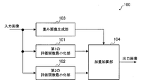
- FIG. 1 is a block diagram schematically showing the configuration of the image processing apparatus 100 according to the first embodiment.
- the image processing device 100 includes a first evaluation function minimization unit 101, a second evaluation function minimization unit 102, a weighted image generation unit 103, and a weight addition unit 104.
- the first evaluation function minimization unit 101 generates the first corrected image by correcting the blur included in the input image.
- the generated first corrected image is given to the weighted addition unit 104.
- the second evaluation function minimization unit 102 generates a second corrected image by correcting the blur included in the input image.
- the generated second corrected image is given to the weight addition unit 104.
- the first evaluation function minimization unit 101 and the second evaluation function minimization unit 102 treat the blur included in the input image as a deconvolution problem and correct the blur.
- the cause of the blur included in the input image is the blur (optical system blur) due to the optical system of the camera which is an imaging device for capturing the input image, or the camera moves when the input image is captured. There is blur (movement blur) etc.
- the input image may be referred to as a blurred image B. This is because the input image contains blur.
- the blurred image B can be modeled by the following equation (1), assuming that the latent image L including no blur is convoluted by a certain point image distribution function K and then the noise N is added.
- * represents a convolution operation.
- the deconvolution problem is that when the blurred image B and the point image distribution function K are given, the latent image L is obtained based on the model of the equation (1), or the blurred image B is given.
- This problem can be mathematically defined as an optimization problem, and is equivalent to finding a latent image L or a latent image L and a point image distribution function K that minimizes an appropriate evaluation function.
- C (L) consists of the sum of the fidelity term and the normalization term, and can be expressed by, for example, the following equation (2).
- w represents a constant and Ds represents a predetermined convolution kernel.
- p represents a norm of order p
- q represents a norm of order q.
- a value of 2 is often used as p and a value of 2 or less is used as q.
- the first term corresponds to the fidelity term.
- the fidelity term is a function that takes the minimum value when the relationship of equation (1) is established.
- the second term in the equation (2) corresponds to a normalization term.
- the normalization term is a term for imposing a certain limit on the solution of an optimization problem. For example, there are a plurality of latent images L that minimize the first term of the equation (2). Therefore, the solution of the optimization problem can be uniquely determined by imposing a certain limit on the latent image L according to the second term of the equation (2).
- ⁇ of the normalization term which is the second term of the equation (2), means that when a plurality of convolution kernels are used as Ds, the sum of the q-th order norms obtained for each convolution kernel is taken. To do.
- the optimization process of the formula (2) is described in detail in, for example, Japanese Patent Publication No. 2016-532367.
- the first evaluation function minimization unit 101 uses a kernel representing the first derivative of the image as Ds.
- the normalization term of the equation (2) becomes smaller as the change in the pixel value of the latent image L becomes smaller or as the latent image L becomes a flat image.
- the larger the number of edges or the gradation portion that monotonically increases or decreases in the latent image L the larger the normalization term of the equation (2) becomes.
- the latent image L becomes an image having poor edges or gradation.
- the evaluation function C (L) can be expressed by the following equation (3) when the kernel representing the first derivative is expressed in a matrix format.
- the first term corresponds to the first derivative in the vertical direction
- the second term corresponds to the first derivative in the horizontal direction.
- W1 represents a first constant corresponding to the constant w in the equation (3).
- the second evaluation function minimization unit 102 in the first embodiment uses a kernel representing the second derivative of the image as Ds.
- the normalization term of the equation (2) takes a small value not only when the change in the pixel value of the latent image L is small but also in the edge or the gradation portion.
- the latent image L is an image in which the change in the pixel value of the edge or the gradation portion is maintained.
- the flat portion in the image is not preserved as it is flat, and an edge-like pattern may appear unnaturally in the portion that should be originally flat.
- the second evaluation function minimization unit 102 is excellent in processing an area where the pixel value has a certain change such as an edge or a gradation, and the first evaluation function minimization unit 101 has a small change in the pixel value. It can be seen that the processing of the area is excellent.
- the evaluation function C (L) can be represented by the following equation (4) when the second-order differential kernel is represented in a matrix format.
- the first term is the vertical derivative
- the second term is the horizontal derivative
- the third term is the diagonal derivative.
- W2 represents a second constant corresponding to the constant w in the equation (4).
- the first evaluation function minimization unit 101 uses the first evaluation function, which becomes a higher evaluation value as the change in the pixel values of the plurality of pixels becomes smaller for the input image including the plurality of pixels.
- the function functions as a first correction processing unit that generates a first corrected image in which the blur of the input image is corrected.
- the first evaluation function is a function for obtaining an evaluation value including a value obtained by multiplying a term representing the magnitude of the first derivative of the input image by a constant (here, the first constant).
- the second evaluation function minimization unit 102 uses the second evaluation function, which becomes a higher evaluation value as the change in the pixel values of the plurality of pixels becomes larger with respect to the input image, to obtain a latent image from the input image. By asking for it, it functions as a second correction processing unit that generates a second corrected image in which the blur of the input image is corrected.
- the second evaluation function is a function for obtaining an evaluation value including a value obtained by multiplying a term representing the magnitude of the second derivative of the input image by a constant (here, the second constant).
- the weight image generation unit 103 determines the variation in the pixel value in the vicinity of each pixel for each pixel of the input image, and specifies the weight value so that the larger the variation in the pixel value, the larger the value. Is.
- the specified weight value is given to the weighted addition unit 104.
- the weight value is 0 or more and 1 or less.
- the weighted image generation unit 103 a case where the dispersion of the pixel values of the input image is used to determine the variation will be shown.
- the weighted image generation unit 103 first identifies each pixel included in the input image as a target pixel, defines a predetermined area including the target pixel, and calculates the variance of the pixel value in the area. To do. Next, the weighted image generation unit 103 maps the variance obtained for the target pixel of the input image to a value of 0 or more and 1 or less. As for the mapping result, the smaller the variance value, the closer to 0, and conversely, the larger the variance value, the closer to 1.
- the variance value ⁇ is set to m, which is a value of 0 or more and 1 or less, by the following equation (5). Can be mapped.
- the mapping method is not limited to the above equation (5), and the larger the value corresponding to the variation of the pixel value obtained in the vicinity of each pixel of the input image is larger than the predetermined threshold value, the closer to 1 and conversely. Anything smaller than a predetermined threshold value may be closer to 0.
- the above value of m can be calculated individually for each pixel of the input image. Therefore, if the value of m calculated individually for each pixel is regarded as the pixel value, the output of the weighted image generation unit 103 can be regarded as if it were an image. Therefore, hereinafter, the output of the weighted image generation unit 103 may be referred to as a weighted image. Further, the pixel value of the weighted image refers to the value of m calculated for each pixel of the input image. The value of m is also referred to as a weight value.
- the weighted addition unit 104 has a first correction image output from the first evaluation function minimization unit 101 and a second evaluation function minimization unit based on the pixel value of the weighted image output by the weight image generation unit 103. An output image that is the result of weighted addition to the second correction image output from 102 is generated.
- the weighted addition unit 104 increases the weight of the second corrected image with respect to the corresponding pixel value as the pixel value of the weighted image increases, and corresponds to the first corrected image as the pixel value of the weighted image decreases. Increase the weight for the pixel value to be used.
- the weight addition unit 104 uses the following equation.
- the value D3 calculated in (6) can be calculated as a pixel value of the output image.
- D1 is the corresponding pixel value of the first corrected image
- D2 is the corresponding pixel value of the second corrected image
- m is the corresponding pixel value (weight value) of the weighted image.
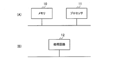
- FIG. 2A A part or all of the first evaluation function minimization unit 101, the second evaluation function minimization unit 102, the weight image generation unit 103, and the weight addition unit 104 described above are shown in FIG. 2A, for example.
- a processor 11 such as a CPU (Central Processing Unit) that executes a program stored in the memory 10.
- a program may be provided through a network, or may be recorded and provided on a recording medium. That is, such a program may be provided as, for example, a program product.
- the first evaluation function minimization unit 101 the second evaluation function minimization unit 102, the weight image generation unit 103, and the weight addition unit 104 are shown in FIG. 2B, for example.
- a processing circuit 12 such as a single circuit, a composite circuit, a programmed processor, a parallel programmed processor, an ASIC (Application Specific Integrated Circuit) or an FPGA (Field Programmable Gate Array).
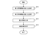
- FIG. 3 is a flowchart showing the operation of the image processing device 100 according to the first embodiment.
- an input unit which is an input device (not shown) of the image processing device 100 receives an instruction from the user. It is started in case etc.
- the first evaluation function minimization unit 101 uses the above equation (3) to generate a first corrected image in which the blur included in the input image is corrected (S10).
- the generated first corrected image is given to the weighted addition unit 104.
- the second evaluation function minimization unit 102 generates a second corrected image in which the blur included in the input image is corrected by using the above equation (4) (S11).
- the generated second corrected image is given to the weight addition unit 104.
- the weighted image generation unit 103 determines the variation in the pixel value in the vicinity of each pixel for each pixel of the input image, and specifies the weight value so that the larger the variation in the pixel value, the larger the value.
- a weighted image showing the specified weight value for each corresponding pixel is generated (S12). The generated weight image is given to the weight addition unit 104.
- the weight addition unit 104 has a first correction image output from the first evaluation function minimization unit 101 and a second evaluation function based on the pixel value of the weight image output by the weight image generation unit 103. An output image is generated as a result of weighted addition of the second correction image output from the minimization unit 102 (S13).
- the weight of the second corrected image becomes heavier at a place where the pixel value includes a certain change, such as an edge portion or a gradation portion of the input image, and conversely, the input image
- the weight of the first corrected image becomes heavier in the place where the change in the pixel value of is small. That is, for each pixel of the input image, the weight of the first evaluation function minimization unit 101 and the second evaluation function minimization unit 102 on the more suitable processing result increases.
- a pixel value suitable for each of a part where the pixel value changes to some extent such as an edge part or a gradation part of the input image and a part where the change in the pixel value of the input image is small is selected. Therefore, it is possible to obtain an output image with few artifacts such as jaggies.
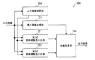
- FIG. 4 is a block diagram schematically showing the configuration of the image processing apparatus 200 according to the second embodiment.
- the image processing device 200 includes a first evaluation function minimization unit 201, a second evaluation function minimization unit 202, a weight image generation unit 103, a weight addition unit 104, and an input image analysis unit 205.
- the weighted image generation unit 103 and the weighted addition unit 104 in the second embodiment are the same as the weighted image generation unit 103 and the weighted addition unit 104 in the first embodiment.
- the constant w of the equation (2) described in the first embodiment is changed according to the characteristics of the input image.
- the constant w of the equation (2) is a value for adjusting the weight between the fidelity term and the normalization term, and the larger the value of the constant w, the larger the ratio of the normalization term to the equation (2).
- the latent image L has a lot of random noise. , The size of the normalization term increases. Therefore, the value calculated by the equation (2) also becomes large.
- both the first evaluation function minimization unit 201 and the second evaluation function minimization unit 202 obtain the latent image L that minimizes the magnitude of the value calculated by the equation (2), and thus correspond to the constant w.
- the values of the first constant w1 and the second constant w2 are increased, an image that does not include random noise is output as the latent image L.
- the latent image L from which the noise has been removed can be obtained by increasing the values of the first constant w1 and the second constant w2.
- the pixel values of fine patterns in the image which are called textures, change randomly, if the values of the first constant w1 and the second constant w2 are made larger than necessary, the texture will appear in the latent image L. It will be lost and an unnatural output image will be obtained.
- the values of the first constant w1 and the second constant w2 may be changed according to the amount of noise contained in the blurred image B, and when the amount of noise is small, the first constant w1 and the second constant w2 It is preferable to reduce the value of and increase the values of the first constant w1 and the second constant w2 when the amount of noise is large. By doing so, if the blurred image B contains a lot of noise, noise processing is appropriately performed, and conversely, if the blurred image B does not contain much noise, the texture is lost more than necessary. It is possible to perform blur correction without any noise.
- the configuration of the second embodiment will be described.
- the input image analysis unit 205 estimates the amount of noise contained in the blurred image B based on the input image, and the first constant w1 and the second constant w2 increase as the estimated noise amount increases. Determine the value.
- the determined first constant w1 is given to the first evaluation function minimization unit 201, and the second constant w2 is given to the second evaluation function minimization unit 202.
- the input image analysis unit 205 determines a predetermined first value as the first constant w1 and the second constant w2, and determines the noise.
- a predetermined second value is determined as the first constant w1 and the second constant w2.
- the first value is a value larger than the second value.
- the input image analysis unit 205 may determine the first constant w1 and the second constant w2 so as to increase monotonically with respect to the amount of noise.
- the noise amount can be defined by the S / N ratio obtained by dividing the signal amount by the variance of the noise amount.
- the signal amount is considered to be the brightness (pixel value).
- the input image analysis unit 205 extracts a representative value which is a representative value from the pixel value of the input image, and sets the extracted representative value as the signal amount S.
- the average value or the mode value of the pixel values in the input image can be used.
- the difference between the maximum value and the minimum value of the pixel values in the input image can be used as a representative value.
- the histogram distribution of the pixel values of the input image is aggregated, and the ones that occupy the predetermined ratios of the upper and lower pixel values are removed as outliers, and then the average value, the mode value, or the most frequent value, or , The difference between the maximum and minimum values can be used as a representative value.
- the S / N can be determined only by the signal amount S obtained as described above.
- the input image analysis unit 205 determines that the larger the value of the signal amount S, the smaller the noise amount, and the smaller the value of the signal amount S, the larger the noise amount. Then, the input image analysis unit 205 may increase the values of the first constant w1 and the second constant w2 as the amount of noise increases.
- the first evaluation function minimization unit 201 generates the first corrected image by correcting the blur included in the input image.
- the generated first corrected image is given to the weighted addition unit 104.
- the first evaluation function minimization unit 201 uses the first constant w1 given by the input image analysis unit 205, and the value represented by the above equation (3) is the minimum.
- the latent image L calculated so as to be the first corrected image is used.
- the second evaluation function minimization unit 202 generates a second corrected image by correcting the blur included in the input image.
- the generated second corrected image is given to the weight addition unit 104.
- the second evaluation function minimization unit 202 uses the second constant w2 given by the input image analysis unit 205, and the value represented by the above equation (4) is the minimum.
- the latent image L calculated so as to be the second corrected image is used.
- a part or all of the first evaluation function minimization unit 201, the second evaluation function minimization unit 202, the weight image generation unit 103, the weight addition unit 104, and the input image analysis unit 205 described above may be described, for example. As shown in FIG. 2A, it can be configured by the memory 10 and the processor 11. Such a program may be provided through a network, or may be recorded and provided on a recording medium. That is, such a program may be provided as, for example, a program product.
- first evaluation function minimization unit 201 the second evaluation function minimization unit 202, the weight image generation unit 103, the weight addition unit 104, and the input image analysis unit 205 are shown in FIG. As shown in B), it can also be configured by the processing circuit 12.
- FIG. 5 is a flowchart showing the operation of the image processing device 200 according to the second embodiment.
- an input unit which is an input device (not shown) of the image processing device 200 receives an instruction from the user. It is started in case etc.
- the input image analysis unit 205 estimates the amount of noise contained in the input image, and determines the values of the first constant w1 and the second constant w2 so that the larger the estimated noise amount, the larger the noise amount (1). S20).
- the determined first constant w1 is given to the first evaluation function minimization unit 201, and the second constant w2 is given to the second evaluation function minimization unit 202.
- the first evaluation function minimization unit 201 uses the first constant w1 given by the input image analysis unit 205 in the equation (3) to correct the blur included in the input image.
- An image is generated (S21).
- the generated first corrected image is given to the weighted addition unit 104.
- the second evaluation function minimization unit 202 uses the second constant w2 given by the input image analysis unit 205 in the equation (4) to correct the blur included in the input image.
- An image is generated (S22).
- the generated second corrected image is given to the weight addition unit 104.
- the weighted image generation unit 103 determines the variation in the pixel value in the vicinity of each pixel for each pixel of the input image, and specifies the weight value so that the larger the variation in the pixel value, the larger the value.
- a weighted image showing the specified weight value for each corresponding pixel is generated (S23). The generated weight image is given to the weight addition unit 104.
- the weight addition unit 104 has a first correction image output from the first evaluation function minimization unit 201 and a second evaluation function based on the pixel value of the weight image output by the weight image generation unit 103.
- An output image is generated as a result of weighted addition of the second correction image output from the minimization unit 202 (S24).
- the blur of the input image can be appropriately corrected according to the amount of noise of the input image.
- the effect in the second embodiment can be obtained. Although it becomes large, the effect in the second embodiment can be obtained only by changing only one of the first constant W1 in the equation (3) and the second constant W2 in the equation (4).
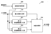
- FIG. 6 is a block diagram schematically showing the configuration of the image processing apparatus 300 according to the third embodiment.
- the image processing device 300 includes a first evaluation function minimization unit 301, a second evaluation function minimization unit 302, a weight image generation unit 103, a weight addition unit 104, and an imaging condition analysis unit 306.
- the weighted image generation unit 103 and the weighted addition unit 104 in the third embodiment are the same as the weighted image generation unit 103 and the weighted addition unit 104 in the first embodiment.
- the noise amount of the input image is estimated by analyzing the input image, but in the third embodiment, the noise amount of the input image is estimated from the imaging conditions of the input image.
- the imaging condition analysis unit 306 acquires imaging conditions from a camera as an imaging device that has captured an input image. Then, the imaging condition analysis unit 306 estimates the noise amount of the input image from the acquired imaging conditions. The imaging condition analysis unit 306 determines the values of the first constant w1 and the second constant w2 so that the larger the estimated noise amount is, the larger the value is. The determined first constant w1 is given to the first evaluation function minimization unit 301, and the second constant w2 is given to the second evaluation function minimization unit 302.
- the imaging condition analysis unit 306 determines a predetermined first value as a first constant w1 and a second constant w2, and determines the noise.
- a predetermined second value is determined as the first constant w1 and the second constant w2.
- the first value is a value larger than the second value.
- the imaging condition analysis unit 306 may determine the first constant w1 and the second constant w2 so as to increase monotonically with respect to the large amount of noise.
- the imaging condition analysis unit 306 takes an imaging time as an argument as an imaging condition, and determines that the longer the imaging time, the smaller the amount of noise. Then, the imaging condition analysis unit 306 determines the values of the first constant w1 and the second constant w2 so that the larger the amount of noise, the larger the first constant w1 and the second constant w2.
- the first evaluation function minimization unit 301 generates the first corrected image by correcting the blur included in the input image.
- the generated first corrected image is given to the weighted addition unit 104.
- the first evaluation function minimization unit 301 uses the first constant w1 given by the image pickup condition analysis unit 306, and the value represented by the above equation (3) is the minimum.
- the latent image L calculated so as to be the first corrected image is used.
- the second evaluation function minimization unit 302 generates a second corrected image by correcting the blur included in the input image.
- the generated second corrected image is given to the weight addition unit 104.
- the second evaluation function minimization unit 302 uses the second constant w2 given by the image pickup condition analysis unit 306, and the value represented by the above equation (4) is the minimum.
- the latent image L calculated so as to be the second corrected image is used.
- a part or all of the first evaluation function minimization unit 301, the second evaluation function minimization unit 302, the weight image generation unit 103, the weight addition unit 104, and the imaging condition analysis unit 306 described above may be described, for example. As shown in FIG. 2A, it can be configured by the memory 10 and the processor 11. Such a program may be provided through a network, or may be recorded and provided on a recording medium. That is, such a program may be provided as, for example, a program product.
- first evaluation function minimization unit 301 the second evaluation function minimization unit 302, the weight image generation unit 103, the weight addition unit 104, and the imaging condition analysis unit 306 are shown in FIG. As shown in B), it can also be configured by the processing circuit 12.
- FIG. 7 is a flowchart showing the operation of the image processing device 300 according to the third embodiment.
- an input unit which is an input device (not shown) of the image processing device 300 receives an instruction from the user. It is started in case etc.
- the imaging condition analysis unit 306 estimates the amount of noise contained in the input image, and determines the values of the first constant w1 and the second constant w2 so that the larger the estimated noise amount, the larger the noise amount (1). S30).
- the determined first constant w1 is given to the first evaluation function minimization unit 301, and the second constant w2 is given to the second evaluation function minimization unit 302.
- the first evaluation function minimization unit 301 uses the first constant w1 given by the imaging condition analysis unit 306 in the equation (3) to correct the blur included in the input image.
- An image is generated (S31).
- the generated first corrected image is given to the weighted addition unit 104.
- the second evaluation function minimization unit 302 uses the second constant w2 given by the imaging condition analysis unit 306 in the equation (4) to correct the blur included in the input image.
- An image is generated (S32).
- the generated second corrected image is given to the weight addition unit 104.
- the weighted image generation unit 103 determines the variation in the pixel value in the vicinity of each pixel for each pixel of the input image, and specifies the weight value so that the larger the variation in the pixel value, the larger the value.
- a weighted image showing the specified weight value for each corresponding pixel is generated (S33). The generated weight image is given to the weight addition unit 104.
- the weight addition unit 104 has a first correction image output from the first evaluation function minimization unit 301 and a second evaluation function based on the pixel value of the weight image output by the weight image generation unit 103.
- An output image is generated as a result of weighted addition of the second correction image output from the minimization unit 302 (S34).
- processing according to the amount of noise contained in the input image becomes possible. Specifically, if the input image contains a lot of noise, noise processing can be performed appropriately, and conversely, if the input image does not contain much noise, blur correction can be performed without losing texture more than necessary. It will be possible.
- the magnitudes of the first constant w1 and the second constant w2 are monotonously non-increasing with respect to the length of the imaging time when the input image is captured.
- the first evaluation function minimization unit 301 and the second evaluation function minimization unit 302 can be controlled so as to be.
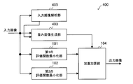
- FIG. 8 is a block diagram schematically showing the configuration of the image processing apparatus 400 according to the fourth embodiment.
- the image processing device 400 includes a first evaluation function minimization unit 101, a second evaluation function minimization unit 102, a weight image generation unit 403, a weight addition unit 104, and an input image analysis unit 405.
- the first evaluation function minimization unit 101, the second evaluation function minimization unit 102, and the weighted addition unit 104 in the fourth embodiment are the first evaluation function minimization unit 101, the second evaluation in the first embodiment. This is the same as the function minimization unit 102 and the weight addition unit 104.
- the first constant w1 and the second constant w2 are adjusted, whereas in the fourth embodiment, the threshold value ⁇ is adjusted instead of the first constant w1 and the second constant w2.
- the threshold value ⁇ is set to a large value, the number of pixels whose pixel value indicating the weight value is close to 0 increases in the weight image, and in the output image, the first correction image output from the first evaluation function minimization unit 101. Will occupy a large proportion.
- the threshold value ⁇ is set to a small value
- the number of pixels whose pixel value indicating the weight value is close to 1 increases in the weight image
- the second evaluation function minimization unit 102 outputs the output image.
- the ratio of the corrected image of is increased.
- the threshold value ⁇ is set to a large value, an output image having a higher effect of removing noise can be obtained from the weighted addition unit 104. Further, since the second corrected image is an image having excellent edge preservation, if the threshold value ⁇ is set to a small value, an output image in which edges are more preserved can be obtained from the weighted addition unit 104.
- the input image analysis unit 405 estimates the amount of noise contained in the blurred image B based on the input image, and determines the value of the threshold value ⁇ so that the larger the estimated amount of noise, the larger the amount of noise.
- the determined threshold value ⁇ is given to the weighted image generation unit 403.
- the method for estimating the amount of noise is the same as in the second embodiment.
- the input image analysis unit 405 determines a predetermined first value as the threshold value ⁇ , and the noise amount is larger than the predetermined threshold value. If it is small, a predetermined second value is determined as the threshold value ⁇ .
- the first value is a value larger than the second value.
- the input image analysis unit 405 may determine the threshold value ⁇ so as to increase monotonically with respect to the large amount of noise.
- the weighted image generation unit 403 determines the variation in the pixel value in the vicinity of each pixel for each pixel of the input image, and specifies the weight value so that the larger the variation in the pixel value, the larger the value.
- the specified weight value is given to the weighted addition unit 104.
- the weight image generation unit 403 calculates the weight value m by the above equation (5), and generates a weight image indicating the weight value m for each pixel.
- the weight image generation unit 403 calculates the weight value m using the threshold value ⁇ given by the input image analysis unit 405. Then, the generated weight image is given to the weight addition unit 104.
- FIG. 9 is a flowchart showing the operation of the image processing device 400 according to the fourth embodiment.
- an input unit which is an input device (not shown) of the image processing device 400 receives an instruction from the user. It is started in case etc.
- the input image analysis unit 405 estimates the amount of noise contained in the input image, and determines the value of the threshold value ⁇ so that the larger the estimated amount of noise, the larger the value (S40).
- the determined threshold value ⁇ is given to the weighted image generation unit 403.
- the first evaluation function minimization unit 101 generates a first corrected image in which the blur included in the input image is corrected by using the equation (3) (S41).
- the generated first corrected image is given to the weighted addition unit 104.
- the second evaluation function minimization unit 102 generates a second corrected image in which the blur included in the input image is corrected by using the equation (4) (S42).
- the generated second corrected image is given to the weight addition unit 104.
- the weighted image generation unit 403 determines the variation in the pixel value in the vicinity of each pixel for each pixel of the input image, and specifies the weight value so that the larger the variation in the pixel value, the larger the value.
- a weighted image showing the specified weight value for each corresponding pixel is generated (S43).
- the weight image generation unit 403 specifies the weight value by using the threshold value ⁇ given by the input image analysis unit 405.
- the generated weight image is given to the weight addition unit 104.
- the weight addition unit 104 has a first correction image output from the first evaluation function minimization unit 101 and a second evaluation function based on the pixel value of the weight image output by the weight image generation unit 403. An output image is generated as a result of weighted addition of the second correction image output from the minimization unit 102 (S44).
- the blur of the input image can be appropriately corrected according to the amount of noise of the input image.
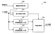
- FIG. 10 is a block diagram schematically showing the configuration of the image processing apparatus 500 according to the fifth embodiment.
- the image processing device 500 includes a first evaluation function minimization unit 101, a second evaluation function minimization unit 102, a weight image generation unit 503, a weight addition unit 104, and an imaging condition analysis unit 506.
- the first evaluation function minimization unit 101, the second evaluation function minimization unit 102, and the weighted addition unit 104 in the fifth embodiment are the first evaluation function minimization unit 101, the second evaluation in the first embodiment. This is the same as the function minimization unit 102 and the weight addition unit 104.
- the noise amount of the input image is estimated by analyzing the input image to determine the threshold value ⁇ , but in the fifth embodiment, the noise amount of the input image is determined by the imaging condition of the input image.
- the threshold value ⁇ is determined by estimating from.
- the imaging condition analysis unit 506 acquires imaging conditions from a camera as an imaging device that has captured an input image. Then, the imaging condition analysis unit 506 estimates the noise amount of the input image from the acquired imaging conditions. The method for estimating the amount of noise is the same as that in the third embodiment.
- the imaging condition analysis unit 506 determines the value of the threshold value ⁇ so that the larger the estimated noise amount, the larger the value.
- the determined threshold value ⁇ is given to the weighted image generation unit 503.
- the imaging condition analysis unit 506 determines a predetermined first value as the threshold value ⁇ , and the noise amount is larger than the predetermined threshold value. If it is small, a predetermined second value is determined as the threshold value ⁇ .
- the first value is a value larger than the second value.
- the imaging condition analysis unit 506 may determine the threshold value ⁇ so as to increase monotonically with respect to the large amount of noise.
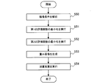
- FIG. 11 is a flowchart showing the operation of the image processing device 500 according to the fifth embodiment.
- an input unit which is an input device (not shown) of the image processing device 500 receives an instruction from the user. It is started in case etc.
- the imaging condition analysis unit 506 estimates the amount of noise contained in the input image, and determines the value of the threshold value ⁇ so that the larger the estimated amount of noise, the larger the value (S50).
- the determined threshold value ⁇ is given to the weighted image generation unit 503.
- the first evaluation function minimization unit 101 generates a first corrected image in which the blur included in the input image is corrected by using the equation (3) (S51).
- the generated first corrected image is given to the weighted addition unit 104.
- the second evaluation function minimization unit 102 generates a second corrected image in which the blur included in the input image is corrected by using the equation (4) (S52).
- the generated second corrected image is given to the weight addition unit 104.
- the weighted image generation unit 503 determines the variation in the pixel value in the vicinity of each pixel for each pixel of the input image, and specifies the weight value so that the larger the variation in the pixel value, the larger the value.
- a weighted image showing the specified weight value for each corresponding pixel is generated (S53).
- the weighted image generation unit 503 specifies the weight value using the threshold value ⁇ given by the imaging condition analysis unit 506.
- the generated weight image is given to the weight addition unit 104.
- the weight addition unit 104 has a first correction image output from the first evaluation function minimization unit 101 and a second evaluation function based on the pixel value of the weight image output by the weight image generation unit 503. An output image is generated as a result of weighted addition of the second correction image output from the minimization unit 102 (S54).
- the fifth embodiment it is possible to perform processing according to the amount of noise contained in the input image. Specifically, if the input image contains a lot of noise, noise processing can be performed appropriately, and conversely, if the input image does not contain much noise, blur correction can be performed without losing texture more than necessary. It will be possible.
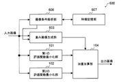
- FIG. 12 is a block diagram schematically showing the configuration of the image processing apparatus 600 according to the sixth embodiment.
- the image processing device 600 includes a first evaluation function minimization unit 101, a second evaluation function minimization unit 102, a weight image generation unit 603, a weight addition unit 104, an imaging condition analysis unit 606, and feature storage.
- a unit 607 is provided.
- the first evaluation function minimization unit 101, the second evaluation function minimization unit 102, and the weighted addition unit 104 in the sixth embodiment are the first evaluation function minimization unit 101, the second evaluation in the first embodiment. This is the same as the function minimization unit 102 and the weight addition unit 104.
- the ratio of the weighted addition in the weighted addition unit 104 can be determined from the information regarding the characteristics of the object shown in the input image, in other words, the imaged object.
- the object shown in the input image is specified by the imaging point which is the imaging point.
- the imaging point is specified by, for example, latitude and longitude
- the feature is determined by the topography of the imaging point with the latitude and longitude as arguments will be described.
- the latitude and longitude of the imaging point in imaging from the sky such as an aircraft-mounted camera, the latitude and longitude of the imaging point (in other words, the point captured by the camera) can be determined from the imaging plan in advance. In this case, the latitude and longitude and the imaging point If you have information (for example, a table) that associates with the terrain, you can determine the characteristics of the imaging point using latitude and longitude as arguments.
- the magnitude of the signal change included in the input image differs depending on whether the image is taken from the sky in a densely populated urban area of houses or buildings and in the case of a terrain with many natural objects such as desert or sea. ..
- the weighted addition unit 104 is more than the second evaluation function minimization unit 102.
- the weighted image generation unit 603 may adjust the weighted image so that the weighted to the second corrected image becomes large.
- the weighted addition unit 104 makes the first correction from the first evaluation function minimization unit 101.
- the weighted image generation unit 603 may adjust the weighted image so that the weight on the image becomes large. By doing so, it is possible to perform image processing more suitable for the subject or the imaging point.
- the feature storage unit 607 stores feature information indicating the features of the terrain corresponding to longitude and latitude.
- the feature information for example, a feature table which is table information in which the feature of the imaging point is associated with the longitude and the latitude may be used based on a prior imaging plan.
- the feature storage unit 607 can be configured by a non-volatile memory or a volatile memory.
- the imaging condition analysis unit 606 acquires imaging conditions from a camera as an imaging device that has captured an input image.
- the imaging conditions the longitude and latitude of the point where the input image is captured are acquired.
- the imaging condition analysis unit 606 identifies the feature corresponding to the acquired longitude and latitude from the feature information stored in the feature storage unit 607. It is assumed that the threshold value ⁇ is set in advance for the feature indicated by the feature information. Therefore, the imaging condition analysis unit 606 can determine the threshold value ⁇ corresponding to the specified feature. The determined threshold value ⁇ is given to the weighted image generation unit 603.
- the size of the threshold value ⁇ is made smaller than a predetermined value, and the second evaluation function minimization unit 102 is used.
- the weight of the corrected image of 2 may be set to a larger value.
- the size of the threshold value ⁇ is made larger than a predetermined value, and the first evaluation function minimization unit is used.
- the weight of the corrected image may be set to a larger value.
- the weighted image generation unit 603 determines the variation in the pixel value in the vicinity of each pixel for each pixel of the input image, and specifies the weight value so that the larger the variation in the pixel value, the larger the value.
- the specified weight value is given to the weighted addition unit 104.
- the weight image generation unit 603 calculates the weight value m according to the above equation (5), and generates a weight image indicating the weight value m for each pixel. Then, the generated weight image is given to the weight addition unit 104.
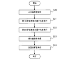
- FIG. 13 is a flowchart showing the operation of the image processing device 600 according to the sixth embodiment.
- an input unit which is an input device (not shown) of the image processing device 600 receives an instruction from the user. It is started in case etc.
- the imaging condition analysis unit 606 acquires the longitude and latitude of the point where the input image is captured by analyzing the metadata as the imaging condition of the input image (S61). Then, the imaging condition analysis unit 606 identifies the feature corresponding to the acquired longitude and latitude by referring to the feature information stored in the feature storage unit 607 (S62). The imaging condition analysis unit 606 gives the weighted image generation unit 603 a threshold value ⁇ corresponding to the specified feature.
- the feature here is the feature of the object to be imaged.
- the first evaluation function minimization unit 101 generates a first corrected image in which the blur included in the input image is corrected by using the equation (3) (S62).
- the generated first corrected image is given to the weighted addition unit 104.
- the second evaluation function minimization unit 102 generates a second corrected image in which the blur included in the input image is corrected by using the equation (4) (S63).
- the generated second corrected image is given to the weight addition unit 104.
- the weighted image generation unit 603 determines the variation in the pixel value in the vicinity of each pixel for each pixel of the input image, and specifies the weight value so that the larger the variation in the pixel value, the larger the value.
- a weighted image showing the specified weight value for each corresponding pixel is generated (S64).
- the weighted image generation unit 603 specifies the weight value by using the threshold value ⁇ given by the imaging condition analysis unit 606. The generated weight image is given to the weight addition unit 104.
- the weight addition unit 104 has a first correction image output from the first evaluation function minimization unit 101 and a second evaluation function based on the pixel value of the weight image output by the weight image generation unit 603. An output image is generated as a result of weighted addition of the second correction image output from the minimization unit 102 (S65).
- the sixth embodiment it is possible to perform processing according to the characteristics of the point where the input image is captured. Specifically, it is possible to perform blur correction according to the target captured by the input image.
- the threshold value ⁇ is determined according to the characteristics of the input image, but the sixth embodiment is not limited to such an example.
- the imaging condition analysis unit 606 may adjust the values of the first constant w1 and the second constant w2 according to the identified features. Specifically, when the specified feature indicates a place where there are many man-made objects such as an urban area, the first constant w1 and the second constant w2 are used in order to reproduce the edge-shaped part with emphasis. The value may be set to a value smaller than a predetermined value. On the contrary, when the specified feature indicates a terrain with many natural objects such as desert or sea, it is considered that there are few edge-shaped parts where the brightness changes rapidly, and conversely there are many flat parts. The values of the constant w1 and the second constant w2 may be set to a value larger than a predetermined value. Even in this case, only one of the first constant w1 and the second constant w2 may be changed.
- the sixth embodiment specifies the characteristics of the input image based on the longitude and the latitude
- the sixth embodiment is not limited to such an example.
- the weight value may be adjusted depending on whether the sea side is taken or the land side is taken. Specifically, when the land side is taken, it is expected that many artificial objects such as houses can be photographed, so it can be expected that many edge-shaped brightness changes can be seen there. Therefore, in such a case, in the weighted addition unit 104, the weighted image is generated by the weighted image generation unit 603 so that the weight from the second evaluation function minimizing unit 102 to the second corrected image becomes larger. You may adjust.
- the weighted image may be adjusted by the weighted image generation unit 603 so that the weighted image is larger.
- the feature information stored in the feature storage unit 607 may be associated with the longitude, the latitude, the imaging direction, and the feature.
Landscapes
- Engineering & Computer Science (AREA)
- Physics & Mathematics (AREA)
- General Physics & Mathematics (AREA)
- Theoretical Computer Science (AREA)
- Multimedia (AREA)
- Signal Processing (AREA)
- Image Processing (AREA)
Abstract
複数の画素を含む入力画像に対して、複数の画素の画素値の変化が小さくなるほど高い評価値となる第1の評価関数を用いて、入力画像から、入力画像にボケが含まれる前の潜在画像を求めることで、入力画像のボケを補正した第1の補正画像を生成する第1の評価関数最小化部(101)と、入力画像に対して、複数の画素の画素値の変化が大きくなるほど高い評価値となる第2の評価関数を用いて、入力画像から潜在画像を求めることで、入力画像のボケを補正した第2の補正画像を生成する第2の評価関数最小化部(102)と、対象領域内の画素の画素値のばらつきが大きいほど、第2の補正画像に対する重みが大きくなるように、複数の画素の各々に対応する重み値を特定する重み値特定部(103)と、複数の画素の各々に対応する重み値を用いて、第1の補正画像及び第2の補正画像の加重加算を行う加重加算部(104)とを備える。
Description
本発明は、画像処理装置及び画像処理方法に関する。
従来の画像処理装置は、撮影画像と点像強度分布とを用いて画像更新処理を行う画像更新手段と、撮影画像又は画像更新処理により生成された少なくとも一つの画像を含む複数の画像に基づいて、複数の画像のそれぞれの画素毎に複数の画像のそれぞれの重みを算出する重み算出手段と、その重みを用いて複数の画像を合成し、回復画像を生成する画像合成手段とを有する(例えば、特許文献1を参照)。
従来の画像処理装置は、画像更新処理により生成した複数の画像の一つを基準画像とし、基準画像との類似度に応じて、画像更新処理により生成した複数の画像に対する重みを決めていた。また、この重みに従い複数の画像を合成していた。そのため、基準画像にジャギー等のアーティファクトが含まれている場合、ジャギー等のアーティファクトと似た処理結果をもつ画像に対する重みが大きくなり、画像合成の結果、ジャギー等のアーティファクトが残ってしまうという問題があった。
本発明の一又は複数の態様は、上記のような問題点を解決するためになされたものであり、ジャギー等のアーティファクトの発生のない画像を得ることを目的としている。
本発明の一態様に係る画像処理装置は、複数の画素を含む入力画像に対して、前記複数の画素の画素値の変化が小さくなるほど高い評価値となる第1の評価関数を用いて、前記入力画像から、前記入力画像にボケが含まれる前の潜在画像を求めることで、前記入力画像のボケを補正した第1の補正画像を生成する第1の補正処理部と、前記入力画像に対して、前記複数の画素の画素値の変化が大きくなるほど高い評価値となる第2の評価関数を用いて、前記入力画像から前記潜在画像を求めることで、前記入力画像のボケを補正した第2の補正画像を生成する第2の補正処理部と、前記複数の画素の各々を対象画素として、前記対象画素を含む予め定められた領域に含まれている画素の画素値のばらつきが大きいほど、前記第2の補正画像に対する重みが大きくなるように、前記対象画素における重み値を特定することで、前記複数の画素の各々に対応する重み値を特定する重み値特定部と、前記複数の画素の各々に対応する重み値を用いて、前記第1の補正画像及び第2の補正画像の加重加算を行う加重加算部と、を備えることを特徴とする。
本発明の一態様に係る画像処理方法は、複数の画素を含む入力画像に対して、前記複数の画素の画素値の変化が小さくなるほど高い評価値となる第1の評価関数を用いて、前記入力画像から、前記入力画像にボケが含まれる前の潜在画像を求めることで、前記入力画像のボケを補正した第1の補正画像を生成し、前記入力画像に対して、前記複数の画素の画素値の変化が大きくなるほど高い評価値となる第2の評価関数を用いて、前記入力画像から前記潜在画像を求めることで、前記入力画像のボケを補正した第2の補正画像を生成し、前記複数の画素の各々を対象画素として、前記対象画素を含む予め定められた領域に含まれている画素の画素値のばらつきが大きいほど、前記第2の補正画像に対する重みが大きくなるように、前記対象画素における重み値を特定することで、前記複数の画素の各々に対応する重み値を特定し、前記複数の画素の各々に対応する重み値を用いて、前記第1の補正画像及び第2の補正画像の加重加算を行うことを特徴とする。
本発明の一又は複数の態様によれば、ジャギー等のアーティファクトの発生のない画像を得ることができる。
実施の形態1.
図1は、実施の形態1に係る画像処理装置100の構成を概略的に示すブロック図である。
画像処理装置100は、第1の評価関数最小化部101と、第2の評価関数最小化部102と、重み画像生成部103と、加重加算部104とを備える。
図1は、実施の形態1に係る画像処理装置100の構成を概略的に示すブロック図である。
画像処理装置100は、第1の評価関数最小化部101と、第2の評価関数最小化部102と、重み画像生成部103と、加重加算部104とを備える。
第1の評価関数最小化部101は、入力画像に含まれるボケを補正することで、第1の補正画像を生成する。生成された第1の補正画像は、加重加算部104に与えられる。
第2の評価関数最小化部102は、入力画像に含まれるボケを補正することで、第2の補正画像を生成する。生成された第2の補正画像は、加重加算部104に与えられる。
第2の評価関数最小化部102は、入力画像に含まれるボケを補正することで、第2の補正画像を生成する。生成された第2の補正画像は、加重加算部104に与えられる。
例えば、第1の評価関数最小化部101及び第2の評価関数最小化部102は、入力画像に含まれるボケをデコンボリューション問題として扱い、そのボケを補正する。
ここで、入力画像に含まれるボケの原因としては、入力画像を撮像するための撮像装置であるカメラの光学系によるボケ(光学系ボケ)、又は、入力画像撮像時にカメラが動いてしまうことによるボケ(動きボケ)等がある。
ここで、入力画像に含まれるボケの原因としては、入力画像を撮像するための撮像装置であるカメラの光学系によるボケ(光学系ボケ)、又は、入力画像撮像時にカメラが動いてしまうことによるボケ(動きボケ)等がある。
以下、デコンボリューション問題について述べる。なお、以下の説明では、入力画像をボケ画像Bということもある。これは入力画像にボケが含まれるためである。
ボケ画像Bは、ぶれを含まない潜在画像Lをある点像分布関数Kで畳み込んだ後、ノイズNを加算したものとして、下記の式(1)でモデル化することができる。

ここで、*は畳み込み演算を表す。
ここでデコンボリューション問題は、ボケ画像Bと、点像分布関数Kとが与えられたときに、式(1)のモデルのもと、潜在画像Lを求める、又は、ボケ画像Bが与えられたときに、式(1)のモデルのもと、潜在画像Lと点像分布関数Kとを求める問題である。
この問題は、数学的には、最適化問題として定義可能で、適切な評価関数を最小化する潜在画像L、又は、潜在画像L及び点像分布関数Kを求めることと等価である。
この問題は、数学的には、最適化問題として定義可能で、適切な評価関数を最小化する潜在画像L、又は、潜在画像L及び点像分布関数Kを求めることと等価である。
以下、点像分布関数Kは既知であるとする。この場合、最小化したい評価関数をC(L)とすると、C(L)は、忠実度項と、正規化項との和からなり、例えば、下記の式(2)で表すことができる。

なお、式(2)で、wは定数を表し、Dsは、予め定められた畳み込みカーネルを表す。また、||・||pは、p次のノルムを表し、||・||qは、q次のノルムを表す。画像処理では、pとしては2が、qとして2以下の値が使われることが多い。
式(2)において、第1項が忠実度項に相当する。忠実度項は、式(1)の関係が成立する場合に、最小値をとる関数である。
また、式(2)における第2項は、正規化項に相当する。正規化項は、最適化問題の解に一定の制限を課すための項である。例えば、式(2)の第1項を最小とする潜在画像Lは、複数個存在する。そこで、式(2)の第2項により潜在画像Lに一定の制限を課すことで最適化問題の解を一意に定めることができる。
また、式(2)における第2項は、正規化項に相当する。正規化項は、最適化問題の解に一定の制限を課すための項である。例えば、式(2)の第1項を最小とする潜在画像Lは、複数個存在する。そこで、式(2)の第2項により潜在画像Lに一定の制限を課すことで最適化問題の解を一意に定めることができる。
ここで、式(2)の第2項である正規化項のΣは、Dsとして複数個の畳み込みカーネルを使用する場合に、各畳み込みカーネルについて得たq次のノルムの和をとることを意味する。
なお、式(2)の最適化処理は、例えば、特表2016-532367号公報に詳細に記載されている。
なお、式(2)の最適化処理は、例えば、特表2016-532367号公報に詳細に記載されている。
ここで、実施の形態1による第1の評価関数最小化部101は、Dsとして画像の1次微分を表すカーネルを用いる。この場合、式(2)の正規化項は、潜在画像Lの画素値の変化が小さいほど、又は、潜在画像Lが平坦な画像になるほど、小さくなる。逆に、潜在画像Lにエッジ、又は、単調に増加若しくは減少するグラデーション部分が多くなるほど、式(2)の正規化項は大きな値となる。言い換えると、Dsとして画像の1次微分を表すカーネルを用いた場合、潜在画像Lは、エッジ又は階調性の乏しい画像となる。
なお、Dsとして1次微分を表すカーネルを用いる場合、1次微分カーネルを行列形式で表すと、評価関数C(L)は、下記の式(3)で表すことができる。

なお、式(3)の正規化項のうち、第1項は、垂直方向の1次微分に、第2項は、水平方向の一次微分に相当する。また、W1は、式(3)における定数wに対応する第1の定数を表す。
一方、実施の形態1における第2の評価関数最小化部102は、Dsとして画像の2次微分を表すカーネルを用いる。この場合、式(2)の正規化項は、潜在画像Lの画素値の変化が小さい場合だけでなく、エッジ又はグラデーション部分でも小さい値をとる。言い換えると、Dsとして画像の2次微分を表すカーネルを用いた場合、潜在画像Lは、エッジ又はグラデーション部の画素値の変化が保たれた画像となる。その一方で、その場合には、画像中の平坦な部分が平坦なまま保存されず、本来平坦であるべき箇所に不自然にエッジ状の模様が現れることがある。
上記から、第2の評価関数最小化部102は、エッジ又はグラデーション等、画素値にある程度の変化がある領域の処理に優れ、第1の評価関数最小化部101は、画素値の変化が少ない領域の処理に優れていることが分かる。
なお、Dsとして、2次微分カーネルを用いる場合、2次微分カーネルを行列形式で表すと、評価関数C(L)は、下記の式(4)で表すことができる。

なお、式(4)の正規化項のうち、第1項は、垂直方向の2次微分に、第2項は、水平方向の2次微分に、第3項は、斜め方向の2次微分に相当する。また、W2は、式(4)における定数wに対応する第2の定数を表す。
以上のように、第1の評価関数最小化部101は、複数の画素を含む入力画像に対して、複数の画素の画素値の変化が小さくなるほど高い評価値となる第1の評価関数を用いて、入力画像から、入力画像にボケが含まれる前の潜在画像を求めることで、入力画像のボケを補正した第1の補正画像を生成する第1の補正処理部として機能する。
ここで、第1の評価関数は、入力画像の1次微分の大きさを表す項に定数(ここでは、第1の定数)を乗じた値を含む評価値を求める関数である。
ここで、第1の評価関数は、入力画像の1次微分の大きさを表す項に定数(ここでは、第1の定数)を乗じた値を含む評価値を求める関数である。
また、第2の評価関数最小化部102は、入力画像に対して、複数の画素の画素値の変化が大きくなるほど高い評価値となる第2の評価関数を用いて、入力画像から潜在画像を求めることで、入力画像のボケを補正した第2の補正画像を生成する第2の補正処理部として機能する。
ここで、第2の評価関数は、入力画像の2次微分の大きさを表す項に定数(ここでは、第2の定数)を乗じた値を含む評価値を求める関数である。
ここで、第2の評価関数は、入力画像の2次微分の大きさを表す項に定数(ここでは、第2の定数)を乗じた値を含む評価値を求める関数である。
重み画像生成部103は、入力画像の各画素について、各画素近傍での画素値のばらつきを判定し、画素値のばらつきが大きいほど、大きな値となるように重み値を特定する重み値特定部である。特定された重み値は、加重加算部104に与えられる。
なお、後述の加重加算部104で行う加重加算を考慮すると、重み値は、0以上1以下の値であることが望ましい。以下、重み画像生成部103の具体的動作例として、ばらつきを判定するために入力画像の画素値の分散を用いる場合を示す。
この場合、重み画像生成部103はまず、入力画像に含まれる各々の画素を対象画素として特定し、この対象画素を含む予め定められた領域を定義し、その領域内の画素値の分散を計算する。
次に、重み画像生成部103は、入力画像の対象画素について求めた分散を0以上1以下の値にマッピングする。なお、マッピングの結果は、分散の値が小さいほど0に近い値をとり、逆に分散の値が大きいほど1に近い値をとるのがよい。
次に、重み画像生成部103は、入力画像の対象画素について求めた分散を0以上1以下の値にマッピングする。なお、マッピングの結果は、分散の値が小さいほど0に近い値をとり、逆に分散の値が大きいほど1に近い値をとるのがよい。
このようなマッピングの方法として、例えば、閾値εを設定し、分散の値がνであったときに、下記の式(5)により、分散の値νを0以上1以下の値であるmにマッピングすることができる。

なお、マッピングの方法は、上記の式(5)に限らず、入力画像の各画素近傍で求めた画素値のばらつきに相当する値が予め定められた閾値より大きいほど、1に近づき、逆に予め定められた閾値より小さいほど0に近づくものであればよい。
また、上記のmの値は、入力画像の各画素について個別の値が計算できる。よって、各画素について個別に計算されるmの値を画素値とみなせば、重み画像生成部103の出力はあたかも画像のようにみなすことができる。そこで、以下、重み画像生成部103の出力を重み画像と呼ぶこともある。また、重み画像の画素値とは、入力画像の各画素について計算されるmの値を指すこととする。なお、mの値は、重み値ともいう。
加重加算部104は、重み画像生成部103の出力する重み画像の画素値に基づき、第1の評価関数最小化部101から出力される第1の補正画像と、第2の評価関数最小化部102から出力される第2の補正画像とを加重加算した結果である出力画像を生成する。
ここで、加重加算部104は、重み画像の画素値が大きいほど、第2の補正画像の対応する画素値に対する重みを大きくし、重み画像の画素値が小さいほど、第1の補正画像の対応する画素値に対する重みを大きくする。
例えば、式(5)に示されているように、重み画像生成部103から出力される重み値が、0以上1以下の値mに制限されている場合、加重加算部104は、下記の式(6)により算出される値D3を、出力画像の画素値として算出することができる。

例えば、式(5)に示されているように、重み画像生成部103から出力される重み値が、0以上1以下の値mに制限されている場合、加重加算部104は、下記の式(6)により算出される値D3を、出力画像の画素値として算出することができる。
ここで、D1は、第1の補正画像の対応する画素値、D2は、第2の補正画像の対応する画素値、mは重み画像の対応する画素値(重み値)である。
以上に記載された第1の評価関数最小化部101、第2の評価関数最小化部102、重み画像生成部103及び加重加算部104の一部又は全部は、例えば、図2(A)に示されているように、メモリ10と、メモリ10に格納されているプログラムを実行するCPU(Central Processing Unit)等のプロセッサ11とにより構成することができる。このようなプログラムは、ネットワークを通じて提供されてもよく、また、記録媒体に記録されて提供されてもよい。即ち、このようなプログラムは、例えば、プログラムプロダクトとして提供されてもよい。
また、第1の評価関数最小化部101、第2の評価関数最小化部102、重み画像生成部103及び加重加算部104の一部又は全部は、例えば、図2(B)に示されているように、単一回路、複合回路、プログラム化したプロセッサ、並列プログラム化したプロセッサ、ASIC(Application Specific Integrated Circuit)又はFPGA(Field Programmable Gate Array)等の処理回路12で構成することもできる。
図3は、実施の形態1に係る画像処理装置100での動作を示すフローチャートである。
図3に示されているフローチャートは、例えば、入力画像が画像処理装置100の図示しない入力インターフェースに入力された場合、画像処理装置100の図示しない入力装置である入力部がユーザから指示を受けた場合等に開始される。
図3に示されているフローチャートは、例えば、入力画像が画像処理装置100の図示しない入力インターフェースに入力された場合、画像処理装置100の図示しない入力装置である入力部がユーザから指示を受けた場合等に開始される。
まず、第1の評価関数最小化部101は、上記の式(3)を用いて、入力画像に含まれるボケを補正した第1の補正画像を生成する(S10)。生成された第1の補正画像は、加重加算部104に与えられる。
次に、第2の評価関数最小化部102は、上記の式(4)を用いて、入力画像に含まれるボケを補正した第2の補正画像を生成する(S11)。生成された第2の補正画像は、加重加算部104に与えられる。
次に、重み画像生成部103は、入力画像の各画素について、各画素近傍での画素値のばらつきを判定し、画素値のばらつきが大きいほど、大きな値となるように重み値を特定し、特定された重み値を対応する画素毎に示す重み画像を生成する(S12)。生成された重み画像は、加重加算部104に与えられる。
次に、加重加算部104は、重み画像生成部103の出力する重み画像の画素値に基づき、第1の評価関数最小化部101から出力される第1の補正画像と、第2の評価関数最小化部102から出力される第2の補正画像とを加重加算した結果である出力画像を生成する(S13)。
以上のように、実施の形態1によれば、入力画像のエッジ部又はグラデーション部等、画素値にある程度の変化が含まれる箇所では第2の補正画像の重みが重くなり、逆に、入力画像の画素値の変化の少ない箇所では、第1の補正画像の重みが重くなる。つまり、入力画像の画素毎に、第1の評価関数最小化部101及び第2の評価関数最小化部102のより適した方の処理結果に対する重みが大きくなる。
このような構成にすることにより、入力画像のエッジ部又はグラデーション部等、画素値にある程度の変化が含まれる箇所と、入力画像の画素値の変化の少ない箇所の各々に適した画素値が選択されるため、ジャギー等のアーティファクトの少ない出力画像を得ることができる。
実施の形態2.
図4は、実施の形態2に係る画像処理装置200の構成を概略的に示すブロック図である。
画像処理装置200は、第1の評価関数最小化部201と、第2の評価関数最小化部202と、重み画像生成部103と、加重加算部104と、入力画像解析部205とを備える。
実施の形態2における重み画像生成部103及び加重加算部104は、実施の形態1における重み画像生成部103及び加重加算部104と同様である。
図4は、実施の形態2に係る画像処理装置200の構成を概略的に示すブロック図である。
画像処理装置200は、第1の評価関数最小化部201と、第2の評価関数最小化部202と、重み画像生成部103と、加重加算部104と、入力画像解析部205とを備える。
実施の形態2における重み画像生成部103及び加重加算部104は、実施の形態1における重み画像生成部103及び加重加算部104と同様である。
実施の形態2は、実施の形態1で説明した式(2)の定数wを入力画像の特性に応じて変化させる。
まず、式(2)の定数wについて説明する。
定数wは、忠実度項と正規化項との間の重みを調整する値であり、定数wの値を大きくするほど、式(2)に占める正規化項の割合が多くなる。
定数wは、忠実度項と正規化項との間の重みを調整する値であり、定数wの値を大きくするほど、式(2)に占める正規化項の割合が多くなる。
Dsとして1次微分を用いる第1の評価関数最小化部201でも、Dsとして2次微分を用いる第2の評価関数最小化部202でも、潜在画像Lにランダムなノイズが多くのっていると、正規化項の大きさが大きくなる。このため、式(2)で算出される値も大きくなる。
一方、第1の評価関数最小化部201も第2の評価関数最小化部202も、式(2)で算出される値の大きさが最小となる潜在画像Lを求めるので、定数wに対応する第1の定数w1及び第2の定数w2の値を大きくするほど、潜在画像Lとして、ランダムなノイズが含まれない画像を出力することになる。
言い換えると、ボケ画像Bにランダムなノイズが多く含まれる場合、第1の定数w1及び第2の定数w2の値を大きくすることでノイズが除去された潜在画像Lを得ることができる。一方で、テキスチャと呼ばれる、画像中にある細かい模様も画素値の変化はランダムであるので、第1の定数w1及び第2の定数w2の値を必要以上に大きくすると、潜在画像Lではテキスチャが失われ、かえって不自然な出力画像が得られることになる。
従って、第1の定数w1及び第2の定数w2の値は、ボケ画像Bに含まれるノイズ量に応じて変えることがよく、ノイズ量が少ないときは第1の定数w1及び第2の定数w2の値を小さくし、ノイズ量が多いときは第1の定数w1及び第2の定数w2の値を大きくするのがよい。このようにすることで、ボケ画像Bにノイズが多く含まれる場合には、ノイズ処理を適度に行い、逆にボケ画像Bにノイズがあまり含まれない場合には、必要以上にテキスチャを失うことなく、ボケ補正を行うことが可能となる。
以下、実施の形態2の構成を説明する。
以下、実施の形態2の構成を説明する。
入力画像解析部205は、入力画像をもとにボケ画像Bに含まれるノイズ量を推定し、推定されたノイズ量が多いほど、大きくなるように第1の定数w1及び第2の定数w2の値を決定する。決定された第1の定数w1は第1の評価関数最小化部201に与えられ及び第2の定数w2は第2の評価関数最小化部202に与えられる。
例えば、入力画像解析部205は、ノイズ量が予め定められた閾値よりも多い場合には、第1の定数w1及び第2の定数w2として、予め定められた第1の値を決定し、ノイズ量が予め定められた閾値よりも少ない場合には、第1の定数w1及び第2の定数w2として、予め定められた第2の値を決定する。ここで、第1の値は第2の値よりも大きな値である。
また、入力画像解析部205は、ノイズ量の多さに対し単調増加となるように第1の定数w1及び第2の定数w2を決定してもよい。
また、入力画像解析部205は、ノイズ量の多さに対し単調増加となるように第1の定数w1及び第2の定数w2を決定してもよい。
以下、入力画像解析部205でのノイズ量の推定方法の一例を述べる。
通常、ノイズ量は、信号量をノイズ量の分散で割ったS/N比で定義できる。
S/N比が大きいほどノイズ量は少なく、逆にS/N比が小さいほどノイズ量は多くなる。
通常、ノイズ量は、信号量をノイズ量の分散で割ったS/N比で定義できる。
S/N比が大きいほどノイズ量は少なく、逆にS/N比が小さいほどノイズ量は多くなる。
本実施の形態で扱う入力画像のように、カメラで得られた画像では、信号量は、輝度(画素値)と考えられる。しかし、画像は、複数の画素からなるため、入力画像中には様々な画素値が現れる。よって、入力画像解析部205は、入力画像の画素値から代表的な値である代表値を抽出し、抽出された代表値を信号量Sとする。
代表値としては、単純な例では、入力画像中の画素値の平均値又は最頻値を使うことができる。また、入力画像中の画素値の最大値と最小値との差を代表値とすることもできる。他にも、入力画像の画素値のヒストグラム分布を集計し、画素値の上位及び下位の予め定められた割合を占めるものはアウトライヤーとして除去した後に算出された、平均値、最頻値、又は、最大値と最小値の差を、代表値として使うことができる。
S/N比を概算する最も単純な例では、上記のように求めた信号量Sでのみ、S/Nを判断することができる。言い換えると、入力画像解析部205は、信号量Sの値が大きいほど、ノイズ量は少ないと判断し、信号量Sの値が小さいほど、ノイズ量は多いと判断する。そして、入力画像解析部205は、ノイズ量が多いほど第1の定数w1及び第2の定数w2の値を大きくすればよい。
なお、上記の中で入力画像の最大値と最小値の差を使うことで、入力画像に一定のオフセット成分がある場合でも、信号量Sを判定することが可能となる。以下、カメラで撮像された入力画像にオフセット成分が発生する例をいくつか示す。
まず、カメラでの撮像として、航空機カメラ等、上空から地表を撮る場合を考える。この場合、カメラと地上の被写体の間に雲があると、雲で太陽光が反射したものが入力画像中にオフセット成分として発生する。また、地上での撮像の場合も、霧の日等は大気中(霧)で散乱した太陽光に由来する入射光がオフセット成分の原因となる。
第1の評価関数最小化部201は、入力画像に含まれるボケを補正することで、第1の補正画像を生成する。生成された第1の補正画像は、加重加算部104に与えられる。
ここで、実施の形態2においては、第1の評価関数最小化部201は、入力画像解析部205から与えられる第1の定数w1を用いて、上記の式(3)で示される値が最小となるように算出した潜在画像Lを、第1の補正画像とする。
ここで、実施の形態2においては、第1の評価関数最小化部201は、入力画像解析部205から与えられる第1の定数w1を用いて、上記の式(3)で示される値が最小となるように算出した潜在画像Lを、第1の補正画像とする。
第2の評価関数最小化部202は、入力画像に含まれるボケを補正することで、第2の補正画像を生成する。生成された第2の補正画像は、加重加算部104に与えられる。
ここで、実施の形態2においては、第2の評価関数最小化部202は、入力画像解析部205から与えられる第2の定数w2を用いて、上記の式(4)で示される値が最小となるように算出した潜在画像Lを、第2の補正画像とする。
ここで、実施の形態2においては、第2の評価関数最小化部202は、入力画像解析部205から与えられる第2の定数w2を用いて、上記の式(4)で示される値が最小となるように算出した潜在画像Lを、第2の補正画像とする。
以上に記載された第1の評価関数最小化部201、第2の評価関数最小化部202、重み画像生成部103、加重加算部104及び入力画像解析部205の一部又は全部は、例えば、図2(A)に示されているように、メモリ10と、プロセッサ11とにより構成することができる。このようなプログラムは、ネットワークを通じて提供されてもよく、また、記録媒体に記録されて提供されてもよい。即ち、このようなプログラムは、例えば、プログラムプロダクトとして提供されてもよい。
また、第1の評価関数最小化部201、第2の評価関数最小化部202、重み画像生成部103、加重加算部104及び入力画像解析部205の一部又は全部は、例えば、図2(B)に示されているように、処理回路12で構成することもできる。
図5は、実施の形態2に係る画像処理装置200での動作を示すフローチャートである。
図5に示されているフローチャートも、例えば、入力画像が画像処理装置200の図示しない入力インターフェースに入力された場合、画像処理装置200の図示しない入力装置である入力部がユーザから指示を受けた場合等に開始される。
図5に示されているフローチャートも、例えば、入力画像が画像処理装置200の図示しない入力インターフェースに入力された場合、画像処理装置200の図示しない入力装置である入力部がユーザから指示を受けた場合等に開始される。
まず、入力画像解析部205は、入力画像に含まれるノイズ量を推定し、推定されたノイズ量が多いほど、大きくなるように第1の定数w1及び第2の定数w2の値を決定する(S20)。決定された第1の定数w1は第1の評価関数最小化部201に与えられ及び第2の定数w2は第2の評価関数最小化部202に与えられる。
次に、第1の評価関数最小化部201は、入力画像解析部205から与えられた第1の定数w1を式(3)に用いて、入力画像に含まれるボケを補正した第1の補正画像を生成する(S21)。生成された第1の補正画像は、加重加算部104に与えられる。
次に、第2の評価関数最小化部202は、入力画像解析部205から与えられた第2の定数w2を式(4)に用いて、入力画像に含まれるボケを補正した第2の補正画像を生成する(S22)。生成された第2の補正画像は、加重加算部104に与えられる。
次に、重み画像生成部103は、入力画像の各画素について、各画素近傍での画素値のばらつきを判定し、画素値のばらつきが大きいほど、大きな値となるように重み値を特定し、特定された重み値を対応する画素毎に示す重み画像を生成する(S23)。生成された重み画像は、加重加算部104に与えられる。
次に、加重加算部104は、重み画像生成部103の出力する重み画像の画素値に基づき、第1の評価関数最小化部201から出力される第1の補正画像と、第2の評価関数最小化部202から出力される第2の補正画像とを加重加算した結果である出力画像を生成する(S24)。
以上のように、実施の形態2によれば、入力画像のノイズ量に応じて、入力画像のボケを適切に補正することができる。
なお、式(3)における第1の定数W1と、式(4)における第2の定数W2との両方を、上記のようにノイズ量に応じて決定することで、実施の形態2における効果は大きくなるが、式(3)における第1の定数W1及び式(4)における第2の定数W2の何れか一方のみを変化させるだけでも、実施の形態2における効果を得ることができる。
なお、式(3)における第1の定数W1と、式(4)における第2の定数W2との両方を、上記のようにノイズ量に応じて決定することで、実施の形態2における効果は大きくなるが、式(3)における第1の定数W1及び式(4)における第2の定数W2の何れか一方のみを変化させるだけでも、実施の形態2における効果を得ることができる。
実施の形態3.
図6は、実施の形態3に係る画像処理装置300の構成を概略的に示すブロック図である。
画像処理装置300は、第1の評価関数最小化部301と、第2の評価関数最小化部302と、重み画像生成部103と、加重加算部104と、撮像条件解析部306とを備える。
実施の形態3における重み画像生成部103及び加重加算部104は、実施の形態1における重み画像生成部103及び加重加算部104と同様である。
図6は、実施の形態3に係る画像処理装置300の構成を概略的に示すブロック図である。
画像処理装置300は、第1の評価関数最小化部301と、第2の評価関数最小化部302と、重み画像生成部103と、加重加算部104と、撮像条件解析部306とを備える。
実施の形態3における重み画像生成部103及び加重加算部104は、実施の形態1における重み画像生成部103及び加重加算部104と同様である。
実施の形態2は、入力画像のノイズ量を、入力画像を解析することにより推定しているが、実施の形態3は、入力画像のノイズ量を、入力画像の撮像条件から推定する。
撮像条件解析部306は、入力画像を撮像した撮像装置としてのカメラから、撮像条件を取得する。そして、撮像条件解析部306は、取得された撮像条件から入力画像のノイズ量を推定する。撮像条件解析部306は、推定されたノイズ量が多いほど、大きくなるように第1の定数w1及び第2の定数w2の値を決定する。決定された第1の定数w1は第1の評価関数最小化部301に与えられ、第2の定数w2は第2の評価関数最小化部302に与えられる。
例えば、撮像条件解析部306は、ノイズ量が予め定められた閾値よりも多い場合には、第1の定数w1及び第2の定数w2として、予め定められた第1の値を決定し、ノイズ量が予め定められた閾値よりも少ない場合には、第1の定数w1及び第2の定数w2として、予め定められた第2の値を決定する。ここで、第1の値は第2の値よりも大きな値である。
また、撮像条件解析部306は、ノイズ量の多さに対し単調増加となるように第1の定数w1及び第2の定数w2を決定してもよい。
また、撮像条件解析部306は、ノイズ量の多さに対し単調増加となるように第1の定数w1及び第2の定数w2を決定してもよい。
一般的に、入力画像に含まれるノイズ量は、撮像時間(露光時間)が長くなるほど少なくなる。よって、撮像条件解析部306は、撮像条件として撮像時間を引数とし、撮像時間が長いほどノイズ量が少ないと判定する。そして、撮像条件解析部306は、ノイズ量が多いほど、第1の定数w1及び第2の定数w2を大きくするように、第1の定数w1及び第2の定数w2の値を決定する。
第1の評価関数最小化部301は、入力画像に含まれるボケを補正することで、第1の補正画像を生成する。生成された第1の補正画像は、加重加算部104に与えられる。
ここで、実施の形態3においては、第1の評価関数最小化部301は、撮像条件解析部306から与えられる第1の定数w1を用いて、上記の式(3)で示される値が最小となるように算出した潜在画像Lを、第1の補正画像とする。
ここで、実施の形態3においては、第1の評価関数最小化部301は、撮像条件解析部306から与えられる第1の定数w1を用いて、上記の式(3)で示される値が最小となるように算出した潜在画像Lを、第1の補正画像とする。
第2の評価関数最小化部302は、入力画像に含まれるボケを補正することで、第2の補正画像を生成する。生成された第2の補正画像は、加重加算部104に与えられる。
ここで、実施の形態3においては、第2の評価関数最小化部302は、撮像条件解析部306から与えられる第2の定数w2を用いて、上記の式(4)で示される値が最小となるように算出した潜在画像Lを、第2の補正画像とする。
ここで、実施の形態3においては、第2の評価関数最小化部302は、撮像条件解析部306から与えられる第2の定数w2を用いて、上記の式(4)で示される値が最小となるように算出した潜在画像Lを、第2の補正画像とする。
以上に記載された第1の評価関数最小化部301、第2の評価関数最小化部302、重み画像生成部103、加重加算部104及び撮像条件解析部306の一部又は全部は、例えば、図2(A)に示されているように、メモリ10と、プロセッサ11とにより構成することができる。このようなプログラムは、ネットワークを通じて提供されてもよく、また、記録媒体に記録されて提供されてもよい。即ち、このようなプログラムは、例えば、プログラムプロダクトとして提供されてもよい。
また、第1の評価関数最小化部301、第2の評価関数最小化部302、重み画像生成部103、加重加算部104及び撮像条件解析部306の一部又は全部は、例えば、図2(B)に示されているように、処理回路12で構成することもできる。
図7は、実施の形態3に係る画像処理装置300での動作を示すフローチャートである。
図7に示されているフローチャートも、例えば、入力画像が画像処理装置300の図示しない入力インターフェースに入力された場合、画像処理装置300の図示しない入力装置である入力部がユーザから指示を受けた場合等に開始される。
図7に示されているフローチャートも、例えば、入力画像が画像処理装置300の図示しない入力インターフェースに入力された場合、画像処理装置300の図示しない入力装置である入力部がユーザから指示を受けた場合等に開始される。
まず、撮像条件解析部306は、入力画像に含まれるノイズ量を推定し、推定されたノイズ量が多いほど、大きくなるように第1の定数w1及び第2の定数w2の値を決定する(S30)。決定された第1の定数w1は第1の評価関数最小化部301に与えられ、第2の定数w2は第2の評価関数最小化部302に与えられる。
次に、第1の評価関数最小化部301は、撮像条件解析部306から与えられた第1の定数w1を式(3)に用いて、入力画像に含まれるボケを補正した第1の補正画像を生成する(S31)。生成された第1の補正画像は、加重加算部104に与えられる。
次に、第2の評価関数最小化部302は、撮像条件解析部306から与えられた第2の定数w2を式(4)に用いて、入力画像に含まれるボケを補正した第2の補正画像を生成する(S32)。生成された第2の補正画像は、加重加算部104に与えられる。
次に、重み画像生成部103は、入力画像の各画素について、各画素近傍での画素値のばらつきを判定し、画素値のばらつきが大きいほど、大きな値となるように重み値を特定し、特定された重み値を対応する画素毎に示す重み画像を生成する(S33)。生成された重み画像は、加重加算部104に与えられる。
次に、加重加算部104は、重み画像生成部103の出力する重み画像の画素値に基づき、第1の評価関数最小化部301から出力される第1の補正画像と、第2の評価関数最小化部302から出力される第2の補正画像とを加重加算した結果である出力画像を生成する(S34)。
以上のように、実施の形態3によれば、入力画像に含まれるノイズ量に応じた処理が可能となる。具体的には、入力画像にノイズが多く含まれる場合はノイズ処理を適度に行い、逆に入力画像にノイズがあまり含まれない場合、必要以上にテキスチャを失うことなく、ボケ補正を行うことが可能となる。
なお、別の表現を用いると、実施の形態3によれば、入力画像を撮像した際の撮像時間の長さに対して第1の定数w1及び第2の定数w2の大きさが単調非増加となるように、第1の評価関数最小化部301及び第2の評価関数最小化部302を制御することができる。
なお、式(3)における第1の定数W1と、式(4)における第2の定数W2との両方を、上記のようにノイズ量に応じて決定することで、実施の形態3における効果は大きくなるが、式(3)における第1の定数W1及び式(4)における第2の定数W2の何れか一方のみを変化させるだけでも、実施の形態3における効果を得ることができる。
なお、式(3)における第1の定数W1と、式(4)における第2の定数W2との両方を、上記のようにノイズ量に応じて決定することで、実施の形態3における効果は大きくなるが、式(3)における第1の定数W1及び式(4)における第2の定数W2の何れか一方のみを変化させるだけでも、実施の形態3における効果を得ることができる。
実施の形態4.
図8は、実施の形態4に係る画像処理装置400の構成を概略的に示すブロック図である。
画像処理装置400は、第1の評価関数最小化部101と、第2の評価関数最小化部102と、重み画像生成部403と、加重加算部104と、入力画像解析部405とを備える。
実施の形態4における第1の評価関数最小化部101、第2の評価関数最小化部102及び加重加算部104は、実施の形態1における第1の評価関数最小化部101、第2の評価関数最小化部102及び加重加算部104と同様である。
図8は、実施の形態4に係る画像処理装置400の構成を概略的に示すブロック図である。
画像処理装置400は、第1の評価関数最小化部101と、第2の評価関数最小化部102と、重み画像生成部403と、加重加算部104と、入力画像解析部405とを備える。
実施の形態4における第1の評価関数最小化部101、第2の評価関数最小化部102及び加重加算部104は、実施の形態1における第1の評価関数最小化部101、第2の評価関数最小化部102及び加重加算部104と同様である。
実施の形態2及び3は、第1の定数w1及び第2の定数w2を調整しているが、実施の形態4は、第1の定数w1及び第2の定数w2の変わりに閾値εを調整する。
閾値εを大きい値に設定すると、重み画像中には、重み値を示す画素値が0に近い画素が増え、出力画像では第1の評価関数最小化部101から出力される第1の補正画像の占める割合が多くなる。
閾値εを大きい値に設定すると、重み画像中には、重み値を示す画素値が0に近い画素が増え、出力画像では第1の評価関数最小化部101から出力される第1の補正画像の占める割合が多くなる。
逆に、閾値εを小さい値に設定すると、重み画像中には、重み値を示す画素値が1に近い画素が増え、出力画像では第2の評価関数最小化部102から出力される第2の補正画像の占める割合が多くなる。
第1の補正画像は、ランダムノイズの除去効果が高いものなので、閾値εを大きい値に設定すると、加重加算部104からも、よりノイズ除去の効果が高い出力画像が得られる。また、第2の補正画像は、エッジの保存性に優れた画像なので、閾値εを小さい値に設定すると加重加算部104からも、よりエッジを保存した出力画像が得られる。
入力画像解析部405は、入力画像をもとにボケ画像Bに含まれるノイズ量を推定し、推定されたノイズ量が多いほど、大きくなるように閾値εの値を決定する。決定された閾値εは、重み画像生成部403に与えられる。
ノイズ量の推定方法については、実施の形態2と同様である。
ノイズ量の推定方法については、実施の形態2と同様である。
例えば、入力画像解析部405は、ノイズ量が予め定められた閾値よりも多い場合には、閾値εとして、予め定められた第1の値を決定し、ノイズ量が予め定められた閾値よりも少ない場合には、閾値εとして、予め定められた第2の値を決定する。ここで、第1の値は第2の値よりも大きな値である。
また、入力画像解析部405は、ノイズ量の多さに対し単調増加となるように閾値εを決定してもよい。
また、入力画像解析部405は、ノイズ量の多さに対し単調増加となるように閾値εを決定してもよい。
重み画像生成部403は、入力画像の各画素について、各画素近傍での画素値のばらつきを判定し、画素値のばらつきが大きいほど、大きな値となるように重み値を特定する。特定された重み値は、加重加算部104に与えられる。
例えば、重み画像生成部403は、上記の式(5)により、重み値mを算出し、画素毎に重み値mを示す重み画像を生成する。ここで、重み画像生成部403は、入力画像解析部405から与えられる閾値εを用いて、重み値mを算出する。そして、生成された重み画像は、加重加算部104に与えられる。
例えば、重み画像生成部403は、上記の式(5)により、重み値mを算出し、画素毎に重み値mを示す重み画像を生成する。ここで、重み画像生成部403は、入力画像解析部405から与えられる閾値εを用いて、重み値mを算出する。そして、生成された重み画像は、加重加算部104に与えられる。
図9は、実施の形態4に係る画像処理装置400での動作を示すフローチャートである。
図9に示されているフローチャートも、例えば、入力画像が画像処理装置400の図示しない入力インターフェースに入力された場合、画像処理装置400の図示しない入力装置である入力部がユーザから指示を受けた場合等に開始される。
図9に示されているフローチャートも、例えば、入力画像が画像処理装置400の図示しない入力インターフェースに入力された場合、画像処理装置400の図示しない入力装置である入力部がユーザから指示を受けた場合等に開始される。
まず、入力画像解析部405は、入力画像に含まれるノイズ量を推定し、推定されたノイズ量が多いほど、大きくなるように閾値εの値を決定する(S40)。決定された閾値εは、重み画像生成部403に与えられる。
次に、第1の評価関数最小化部101は、式(3)を用いて、入力画像に含まれるボケを補正した第1の補正画像を生成する(S41)。生成された第1の補正画像は、加重加算部104に与えられる。
次に、第2の評価関数最小化部102は、式(4)を用いて、入力画像に含まれるボケを補正した第2の補正画像を生成する(S42)。生成された第2の補正画像は、加重加算部104に与えられる。
次に、重み画像生成部403は、入力画像の各画素について、各画素近傍での画素値のばらつきを判定し、画素値のばらつきが大きいほど、大きな値となるように重み値を特定し、特定された重み値を対応する画素毎に示す重み画像を生成する(S43)。ここでは、重み画像生成部403は、入力画像解析部405から与えられた閾値εを用いて、重み値を特定する。生成された重み画像は、加重加算部104に与えられる。
次に、加重加算部104は、重み画像生成部403の出力する重み画像の画素値に基づき、第1の評価関数最小化部101から出力される第1の補正画像と、第2の評価関数最小化部102から出力される第2の補正画像とを加重加算した結果である出力画像を生成する(S44)。
以上のように、実施の形態4によれば、入力画像のノイズ量に応じて、入力画像のボケを適切に補正することができる。
実施の形態5.
図10は、実施の形態5に係る画像処理装置500の構成を概略的に示すブロック図である。
画像処理装置500は、第1の評価関数最小化部101と、第2の評価関数最小化部102と、重み画像生成部503と、加重加算部104と、撮像条件解析部506とを備える。
実施の形態5における第1の評価関数最小化部101、第2の評価関数最小化部102及び加重加算部104は、実施の形態1における第1の評価関数最小化部101、第2の評価関数最小化部102及び加重加算部104と同様である。
図10は、実施の形態5に係る画像処理装置500の構成を概略的に示すブロック図である。
画像処理装置500は、第1の評価関数最小化部101と、第2の評価関数最小化部102と、重み画像生成部503と、加重加算部104と、撮像条件解析部506とを備える。
実施の形態5における第1の評価関数最小化部101、第2の評価関数最小化部102及び加重加算部104は、実施の形態1における第1の評価関数最小化部101、第2の評価関数最小化部102及び加重加算部104と同様である。
実施の形態4は、入力画像のノイズ量を、入力画像を解析することにより推定して閾値εを決定しているが、実施の形態5は、入力画像のノイズ量を、入力画像の撮像条件から推定して閾値εを決定する。
撮像条件解析部506は、入力画像を撮像した撮像装置としてのカメラから、撮像条件を取得する。そして、撮像条件解析部506は、取得された撮像条件から入力画像のノイズ量を推定する。ノイズ量の推定方法は、実施の形態3と同様である。
そして、撮像条件解析部506は、推定されたノイズ量が多いほど、大きくなるように閾値εの値を決定する。決定された閾値εは、重み画像生成部503に与えられる。
例えば、撮像条件解析部506は、ノイズ量が予め定められた閾値よりも多い場合には、閾値εとして、予め定められた第1の値を決定し、ノイズ量が予め定められた閾値よりも少ない場合には、閾値εとして、予め定められた第2の値を決定する。ここで、第1の値は第2の値よりも大きな値である。
また、撮像条件解析部506は、ノイズ量の多さに対し単調増加となるように閾値εを決定してもよい。
また、撮像条件解析部506は、ノイズ量の多さに対し単調増加となるように閾値εを決定してもよい。
図11は、実施の形態5に係る画像処理装置500での動作を示すフローチャートである。
図11に示されているフローチャートも、例えば、入力画像が画像処理装置500の図示しない入力インターフェースに入力された場合、画像処理装置500の図示しない入力装置である入力部がユーザから指示を受けた場合等に開始される。
図11に示されているフローチャートも、例えば、入力画像が画像処理装置500の図示しない入力インターフェースに入力された場合、画像処理装置500の図示しない入力装置である入力部がユーザから指示を受けた場合等に開始される。
まず、撮像条件解析部506は、入力画像に含まれるノイズ量を推定し、推定されたノイズ量が多いほど、大きくなるように閾値εの値を決定する(S50)。決定された閾値εは、重み画像生成部503に与えられる。
次に、第1の評価関数最小化部101は、式(3)を用いて、入力画像に含まれるボケを補正した第1の補正画像を生成する(S51)。生成された第1の補正画像は、加重加算部104に与えられる。
次に、第2の評価関数最小化部102は、式(4)を用いて、入力画像に含まれるボケを補正した第2の補正画像を生成する(S52)。生成された第2の補正画像は、加重加算部104に与えられる。
次に、重み画像生成部503は、入力画像の各画素について、各画素近傍での画素値のばらつきを判定し、画素値のばらつきが大きいほど、大きな値となるように重み値を特定し、特定された重み値を対応する画素毎に示す重み画像を生成する(S53)。ここでは、重み画像生成部503は、撮像条件解析部506から与えられた閾値εを用いて、重み値を特定する。生成された重み画像は、加重加算部104に与えられる。
次に、加重加算部104は、重み画像生成部503の出力する重み画像の画素値に基づき、第1の評価関数最小化部101から出力される第1の補正画像と、第2の評価関数最小化部102から出力される第2の補正画像とを加重加算した結果である出力画像を生成する(S54)。
以上のように、実施の形態5によれば、入力画像に含まれるノイズ量に応じた処理が可能となる。具体的には、入力画像にノイズが多く含まれる場合はノイズ処理を適度に行い、逆に入力画像にノイズがあまり含まれない場合、必要以上にテキスチャを失うことなく、ボケ補正を行うことが可能となる。
実施の形態6.
図12は、実施の形態6に係る画像処理装置600の構成を概略的に示すブロック図である。
画像処理装置600は、第1の評価関数最小化部101と、第2の評価関数最小化部102と、重み画像生成部603と、加重加算部104と、撮像条件解析部606と、特徴記憶部607とを備える。
実施の形態6における第1の評価関数最小化部101、第2の評価関数最小化部102及び加重加算部104は、実施の形態1における第1の評価関数最小化部101、第2の評価関数最小化部102及び加重加算部104と同様である。
図12は、実施の形態6に係る画像処理装置600の構成を概略的に示すブロック図である。
画像処理装置600は、第1の評価関数最小化部101と、第2の評価関数最小化部102と、重み画像生成部603と、加重加算部104と、撮像条件解析部606と、特徴記憶部607とを備える。
実施の形態6における第1の評価関数最小化部101、第2の評価関数最小化部102及び加重加算部104は、実施の形態1における第1の評価関数最小化部101、第2の評価関数最小化部102及び加重加算部104と同様である。
実施の形態6は、加重加算部104での加重加算の割合を、入力画像に写っている対象、言い換えると、撮像される対象の特徴に関する情報から決めることができる。ここで、入力画像に写っている対象は、撮像が行われた地点である撮像地点により特定されるものとする。撮像地点は、例えば、緯度及び経度により特定され、緯度及び経度を引数に撮像地点の地形により特徴を判断する場合を説明する。
例えば、航空機搭載カメラ等の上空からの撮像では、事前の撮像計画から撮像地点(言い換えると、カメラに写っている地点)の緯度及び経度を判断でき、この場合、緯度及び経度と、撮像地点の地形とを対応付ける情報(例えば、テーブル)を持っておけば、緯度及び経度を引数に撮像地点の特徴を決めることができる。
撮像地点として、例えば、上空から住宅又はビルの密集した都市部を写した場合と、砂漠又は海上といった自然物が多い地形を写した場合とでは、そもそも入力画像に含まれる信号変化の大きさが異なる。
具体的には、都市部等の人工物が多い場合、建物と建物との境目等のようにエッジが多いと考えられるので、加重加算部104でより第2の評価関数最小化部102からの第2の補正画像に対する重みが大きくなるように重み画像生成部603で重み画像を調整してもよい。
逆に、砂漠又は海上といった自然物が多い地形では輝度が急激に変化するエッジ状の箇所は少ないと考えられるので、加重加算部104でより第1の評価関数最小化部101からの第1の補正画像に対する重みが大きくなるように重み画像生成部603で重み画像を調整してもよい。
このようにすることで、被写体あるいは撮像地点により適した画像処理を実施することができる。
逆に、砂漠又は海上といった自然物が多い地形では輝度が急激に変化するエッジ状の箇所は少ないと考えられるので、加重加算部104でより第1の評価関数最小化部101からの第1の補正画像に対する重みが大きくなるように重み画像生成部603で重み画像を調整してもよい。
このようにすることで、被写体あるいは撮像地点により適した画像処理を実施することができる。
特徴記憶部607は、経度及び緯度に対応する地形の特徴を示す特徴情報を記憶する。特徴情報としては、例えば、事前の撮像計画に基づいて、撮像地点の特徴と、経度及び緯度とを対応付けたテーブル情報である特徴テーブルが用いられればよい。
なお、特徴記憶部607は、不揮発性メモリ又は揮発性メモリにより構成することができる。
なお、特徴記憶部607は、不揮発性メモリ又は揮発性メモリにより構成することができる。
撮像条件解析部606は、入力画像を撮像した撮像装置としてのカメラから、撮像条件を取得する。ここでは、撮像条件として、入力画像が撮像された地点の経度及び緯度を取得する。
そして、撮像条件解析部606は、特徴記憶部607に記憶されている特徴情報から、取得された経度及び緯度に対応する特徴を特定する。なお、特徴情報で示されている特徴には、予め閾値εが定められているものとする。このため、撮像条件解析部606は、特定された特徴に対応する閾値εを決定することができる。決定された閾値εは、重み画像生成部603に与えられる。
そして、撮像条件解析部606は、特徴記憶部607に記憶されている特徴情報から、取得された経度及び緯度に対応する特徴を特定する。なお、特徴情報で示されている特徴には、予め閾値εが定められているものとする。このため、撮像条件解析部606は、特定された特徴に対応する閾値εを決定することができる。決定された閾値εは、重み画像生成部603に与えられる。
例えば、特定された特徴が、都市部等の人工物が多い場所を示す場合には、閾値εの大きさを予め定められた値より小さくし、第2の評価関数最小化部102からの第2の補正画像への重みがより大きな値になるようにすればよい。
逆に、特定された特徴が、砂漠又は海上といった自然物が多い地形を示す場合には、閾値εの大きさを予め定められた値より大きくし、第1の評価関数最小化部からの第1の補正画像への重みがより大きな値になるようにすればよい。
逆に、特定された特徴が、砂漠又は海上といった自然物が多い地形を示す場合には、閾値εの大きさを予め定められた値より大きくし、第1の評価関数最小化部からの第1の補正画像への重みがより大きな値になるようにすればよい。
重み画像生成部603は、入力画像の各画素について、各画素近傍での画素値のばらつきを判定し、画素値のばらつきが大きいほど、大きな値となるように重み値を特定する。特定された重み値は、加重加算部104に与えられる。
例えば、重み画像生成部603は、上記の式(5)により、重み値mを算出し、画素毎に重み値mを示す重み画像を生成する。そして、生成された重み画像は、加重加算部104に与えられる。
例えば、重み画像生成部603は、上記の式(5)により、重み値mを算出し、画素毎に重み値mを示す重み画像を生成する。そして、生成された重み画像は、加重加算部104に与えられる。
図13は、実施の形態6に係る画像処理装置600での動作を示すフローチャートである。
図13に示されているフローチャートも、例えば、入力画像が画像処理装置600の図示しない入力インターフェースに入力された場合、画像処理装置600の図示しない入力装置である入力部がユーザから指示を受けた場合等に開始される。
図13に示されているフローチャートも、例えば、入力画像が画像処理装置600の図示しない入力インターフェースに入力された場合、画像処理装置600の図示しない入力装置である入力部がユーザから指示を受けた場合等に開始される。
まず、撮像条件解析部606は、入力画像の撮像条件としてのメタデータを解析することで、入力画像が撮像された地点の経度及び緯度を取得する(S61)。
そして、撮像条件解析部606は、特徴記憶部607に記憶されている特徴情報を参照して、取得された経度及び緯度に対応する特徴を特定する(S62)。撮像条件解析部606は、特定された特徴に対応する閾値εを、重み画像生成部603に与える。ここでの特徴は、撮像される対象の特徴である。
そして、撮像条件解析部606は、特徴記憶部607に記憶されている特徴情報を参照して、取得された経度及び緯度に対応する特徴を特定する(S62)。撮像条件解析部606は、特定された特徴に対応する閾値εを、重み画像生成部603に与える。ここでの特徴は、撮像される対象の特徴である。
次に、第1の評価関数最小化部101は、式(3)を用いて、入力画像に含まれるボケを補正した第1の補正画像を生成する(S62)。生成された第1の補正画像は、加重加算部104に与えられる。
次に、第2の評価関数最小化部102は、式(4)を用いて、入力画像に含まれるボケを補正した第2の補正画像を生成する(S63)。生成された第2の補正画像は、加重加算部104に与えられる。
次に、重み画像生成部603は、入力画像の各画素について、各画素近傍での画素値のばらつきを判定し、画素値のばらつきが大きいほど、大きな値となるように重み値を特定し、特定された重み値を対応する画素毎に示す重み画像を生成する(S64)。ここでは、重み画像生成部603は、撮像条件解析部606から与えられた閾値εを用いて、重み値を特定する。生成された重み画像は、加重加算部104に与えられる。
次に、加重加算部104は、重み画像生成部603の出力する重み画像の画素値に基づき、第1の評価関数最小化部101から出力される第1の補正画像と、第2の評価関数最小化部102から出力される第2の補正画像とを加重加算した結果である出力画像を生成する(S65)。
以上のように、実施の形態6によれば、入力画像が撮像された地点の特徴に応じた処理が可能となる。具体的には、入力画像で撮像された対象に応じたボケ補正を行うことが可能となる。
以上に記載された実施の形態6では、入力画像の特徴に応じて、閾値εを決定しているが、実施の形態6はこのような例に限定されない。
例えば、撮像条件解析部606は、特定された特徴に応じて、第1の定数w1及び第2の定数w2の値を調整してもよい。具体的には、特定された特徴が都市部等の人工物が多い場所を示す場合には、エッジ状の箇所を重視して再現するために、第1の定数w1及び第2の定数w2の値を予め定められた値よりも小さい値にすればよい。
逆に、特定された特徴が砂漠又は海上といった自然物が多い地形を示す場合には、輝度が急激に変化するエッジ状の箇所は少なく、逆に平坦な箇所が多いと考えられるため、第1の定数w1及び第2の定数w2の値を予め定められた値よりも大きい値にすればよい。
なお、この場合でも、第1の定数w1及び第2の定数w2の何れか一方のみが変化されてもよい。
また、実施の形態6は、経度及び緯度に基づいて、入力画像の特徴を特定しているが、実施の形態6は、このような例に限定されない。
例えば、監視カメラ等のカメラで、海岸沿いの地点から周囲の景色を撮像する場合、海側をとるか、陸側をとるかで重み値が調整されてもよい。
具体的には、陸側をとる場合、住宅等の人工物が多く撮れることが予想されるので、そこにはエッジ状の輝度変化が多く見られると予想できる。従って、このような場合には、加重加算部104において、より第2の評価関数最小化部102からの第2の補正画像への重みがより大きくなるように重み画像生成部603で重み画像を調整してもよい。
逆に海側をとる場合、海又は空といった輝度変化があまり見られないものが多く撮れることが予想されるので、その場合は、第1の評価関数最小化部101からの第1の補正画像への重みがより大きくなるように重み画像生成部603で重み画像を調整してもよい。
このような場合、入力画像のメタデータに含まれている、緯度及び経度と、撮影方向とを引数に撮像地点の特徴を定めることが可能である。
このため、特徴記憶部607に記憶されている特徴情報が、経度及び緯度並びに撮像方向と、特徴とを対応付けておけばよい。
このため、特徴記憶部607に記憶されている特徴情報が、経度及び緯度並びに撮像方向と、特徴とを対応付けておけばよい。
100,200,300,400,500,600 画像処理装置、 101,201,301 第1の評価関数最小化部、 102,202,302 第2の評価関数最小化部、 103,403,503,603 重み画像生成部、 104 加重加算部、 205,405 入力画像解析部、 306,506,606 撮像条件解析部、 607 特徴記憶部。
Claims (10)
- 複数の画素を含む入力画像に対して、前記複数の画素の画素値の変化が小さくなるほど高い評価値となる第1の評価関数を用いて、前記入力画像から、前記入力画像にボケが含まれる前の潜在画像を求めることで、前記入力画像のボケを補正した第1の補正画像を生成する第1の補正処理部と、
前記入力画像に対して、前記複数の画素の画素値の変化が大きくなるほど高い評価値となる第2の評価関数を用いて、前記入力画像から前記潜在画像を求めることで、前記入力画像のボケを補正した第2の補正画像を生成する第2の補正処理部と、
前記複数の画素の各々を対象画素として、前記対象画素を含む予め定められた領域に含まれている画素の画素値のばらつきが大きいほど、前記第2の補正画像に対する重みが大きくなるように、前記対象画素における重み値を特定することで、前記複数の画素の各々に対応する重み値を特定する重み値特定部と、
前記複数の画素の各々に対応する重み値を用いて、前記第1の補正画像及び第2の補正画像の加重加算を行う加重加算部と、を備えること
を特徴とする画像処理装置。 - 前記第1の評価関数は、前記入力画像の1次微分の大きさを表す項に第1の定数を乗じた値を含む評価値を求める関数であり、
前記第2の評価関数は、前記入力画像の2次微分の大きさを表す項に第2の定数を乗じた値を含む評価値を求める関数であること
を特徴とする請求項1に記載の画像処理装置。 - 前記入力画像に含まれているノイズ量を推定し、前記推定されたノイズ量が多いほど、大きくなるように前記第1の定数及び前記第2の定数の少なくとも何れか一方の値を決定する入力画像解析部をさらに備えること
を特徴とする請求項2に記載の画像処理装置。 - 前記重み値特定部は、前記ばらつきが閾値を超えた場合に、前記第2の補正画像に対する重みが大きくなるように、前記対象画素における重み値を特定し、
前記入力画像に含まれているノイズ量を推定し、前記推定されたノイズ量が多いほど、大きくなるように前記閾値を決定する入力画像解析部をさらに備えること
を特徴とする請求項1又は2に記載の画像処理装置。 - 前記入力画像解析部は、前記複数の画素の画素値における代表的な値である代表値が小さいほど、前記ノイズ量が多いと推定すること
を特徴とする請求項3又は4に記載の画像処理装置。 - 前記入力画像は、撮像装置により撮像された画像であり、
前記撮像装置から、前記入力画像を撮像した際の撮像条件を取得し、前記撮像条件から、前記入力画像に含まれているノイズ量を推定し、前記推定されたノイズ量が多いほど、大きくなるように前記第1の定数及び前記第2の定数の少なくとも何れか一方の値を決定する撮像条件解析部をさらに備えること
を特徴とする請求項2に記載の画像処理装置。 - 前記重み値特定部は、前記ばらつきが閾値を超えた場合に、前記第2の補正画像に対する重みが大きくなるように、前記対象画素における重み値を特定し、
前記入力画像は、撮像装置により撮像された画像であり、
前記撮像装置から、前記入力画像を撮像した際の撮像条件を取得し、前記撮像条件から、前記入力画像に含まれているノイズ量を推定し、前記推定されたノイズ量が多いほど、大きくなるように前記閾値を決定する撮像条件解析部をさらに備えること
を特徴とする請求項1又は2に記載の画像処理装置。 - 前記撮像条件解析部は、前記撮像条件に含まれている露光時間が長いほど、前記ノイズ量が少ないと推定すること
を特徴とする請求項6又は7に記載の画像処理装置。 - 前記撮像条件解析部は、前記撮像条件に含まれている撮像される対象に関する情報から、前記ノイズ量を推定すること
を特徴とする請求項6又は7に記載の画像処理装置。 - 複数の画素を含む入力画像に対して、前記複数の画素の画素値の変化が小さくなるほど高い評価値となる第1の評価関数を用いて、前記入力画像から、前記入力画像にボケが含まれる前の潜在画像を求めることで、前記入力画像のボケを補正した第1の補正画像を生成し、
前記入力画像に対して、前記複数の画素の画素値の変化が大きくなるほど高い評価値となる第2の評価関数を用いて、前記入力画像から前記潜在画像を求めることで、前記入力画像のボケを補正した第2の補正画像を生成し、
前記複数の画素の各々を対象画素として、前記対象画素を含む予め定められた領域に含まれている画素の画素値のばらつきが大きいほど、前記第2の補正画像に対する重みが大きくなるように、前記対象画素における重み値を特定することで、前記複数の画素の各々に対応する重み値を特定し、
前記複数の画素の各々に対応する重み値を用いて、前記第1の補正画像及び第2の補正画像の加重加算を行うこと
を特徴とする画像処理方法。
Priority Applications (2)
| Application Number | Priority Date | Filing Date | Title |
|---|---|---|---|
| JP2021525533A JP7146088B2 (ja) | 2019-06-14 | 2019-06-14 | 画像処理装置及び画像処理方法 |
| PCT/JP2019/023632 WO2020250412A1 (ja) | 2019-06-14 | 2019-06-14 | 画像処理装置及び画像処理方法 |
Applications Claiming Priority (1)
| Application Number | Priority Date | Filing Date | Title |
|---|---|---|---|
| PCT/JP2019/023632 WO2020250412A1 (ja) | 2019-06-14 | 2019-06-14 | 画像処理装置及び画像処理方法 |
Publications (1)
| Publication Number | Publication Date |
|---|---|
| WO2020250412A1 true WO2020250412A1 (ja) | 2020-12-17 |
Family
ID=73781590
Family Applications (1)
| Application Number | Title | Priority Date | Filing Date |
|---|---|---|---|
| PCT/JP2019/023632 Ceased WO2020250412A1 (ja) | 2019-06-14 | 2019-06-14 | 画像処理装置及び画像処理方法 |
Country Status (2)
| Country | Link |
|---|---|
| JP (1) | JP7146088B2 (ja) |
| WO (1) | WO2020250412A1 (ja) |
Citations (2)
| Publication number | Priority date | Publication date | Assignee | Title |
|---|---|---|---|---|
| WO2014148074A1 (ja) * | 2013-03-18 | 2014-09-25 | 富士フイルム株式会社 | 復元フィルタ生成装置及び方法、画像処理装置及び方法、撮像装置、プログラム、並びに記録媒体 |
| WO2016171087A1 (ja) * | 2015-04-23 | 2016-10-27 | 富士フイルム株式会社 | 画像処理装置、撮像装置、画像処理方法及び画像処理プログラム |
-
2019
- 2019-06-14 WO PCT/JP2019/023632 patent/WO2020250412A1/ja not_active Ceased
- 2019-06-14 JP JP2021525533A patent/JP7146088B2/ja active Active
Patent Citations (2)
| Publication number | Priority date | Publication date | Assignee | Title |
|---|---|---|---|---|
| WO2014148074A1 (ja) * | 2013-03-18 | 2014-09-25 | 富士フイルム株式会社 | 復元フィルタ生成装置及び方法、画像処理装置及び方法、撮像装置、プログラム、並びに記録媒体 |
| WO2016171087A1 (ja) * | 2015-04-23 | 2016-10-27 | 富士フイルム株式会社 | 画像処理装置、撮像装置、画像処理方法及び画像処理プログラム |
Also Published As
| Publication number | Publication date |
|---|---|
| JPWO2020250412A1 (ja) | 2021-10-21 |
| JP7146088B2 (ja) | 2022-10-03 |
Similar Documents
| Publication | Publication Date | Title |
|---|---|---|
| Galdran | Image dehazing by artificial multiple-exposure image fusion | |
| CN113992861B (zh) | 一种图像处理方法及图像处理装置 | |
| US8358865B2 (en) | Device and method for gradient domain image deconvolution | |
| CN102905058B (zh) | 产生去除了重影模糊的高动态范围图像的设备和方法 | |
| CN108416754B (zh) | 一种自动去除鬼影的多曝光图像融合方法 | |
| Hee Park et al. | Gyro-based multi-image deconvolution for removing handshake blur | |
| US20170365046A1 (en) | Algorithm and device for image processing | |
| JP4999680B2 (ja) | 画像ノイズを低減することによる画像データ処理方法および該方法を実行するカメラ組み込み手段 | |
| Jia et al. | Bayesian correction of image intensity with spatial consideration | |
| JP4454657B2 (ja) | ぶれ補正装置及び方法、並びに撮像装置 | |
| KR102106537B1 (ko) | 하이 다이나믹 레인지 영상 생성 방법 및, 그에 따른 장치, 그에 따른 시스템 | |
| JP2013192224A (ja) | ブラー映像及びノイズ映像で構成されたマルチフレームを用いて非均一モーションブラーを除去する方法及び装置 | |
| JP7767338B2 (ja) | 画像処理方法、画像処理装置、画像処理システム、およびプログラム | |
| JPWO2016189901A1 (ja) | 画像処理装置、画像処理方法、プログラム、これを記録した記録媒体、映像撮影装置、及び映像記録再生装置 | |
| CN106375675B (zh) | 一种航空相机多曝光图像融合方法 | |
| Rabie | Adaptive hybrid mean and median filtering of high-ISO long-exposure sensor noise for digital photography | |
| JP6541454B2 (ja) | 画像処理装置、撮像装置、画像処理方法、画像処理プログラム、および、記憶媒体 | |
| Jin et al. | Image dehazing using non-local haze-lines and multi-exposure fusion | |
| KR101437898B1 (ko) | 단일 영상을 이용한 hdr 영상 생성 장치 및 방법 | |
| CN114866705A (zh) | 自动曝光方法、存储介质及电子设备 | |
| CN113034553B (zh) | 图像配准算法的评估方法、终端及存储介质 | |
| JP4859516B2 (ja) | 画像処理装置および画像復元方法 | |
| JP7146088B2 (ja) | 画像処理装置及び画像処理方法 | |
| KR101468433B1 (ko) | 결합된 색상 채널 변환 맵을 이용한 다이나믹 레인지 확장 장치 및 방법 | |
| Wang et al. | An airlight estimation method for image dehazing based on gray projection |
Legal Events
| Date | Code | Title | Description |
|---|---|---|---|
| 121 | Ep: the epo has been informed by wipo that ep was designated in this application |
Ref document number: 19932586 Country of ref document: EP Kind code of ref document: A1 |
|
| ENP | Entry into the national phase |
Ref document number: 2021525533 Country of ref document: JP Kind code of ref document: A |
|
| NENP | Non-entry into the national phase |
Ref country code: DE |
|
| 122 | Ep: pct application non-entry in european phase |
Ref document number: 19932586 Country of ref document: EP Kind code of ref document: A1 |