WO2020250412A1 - Dispositif de traitement d'image et procédé de traitement d'image - Google Patents
Dispositif de traitement d'image et procédé de traitement d'image Download PDFInfo
- Publication number
- WO2020250412A1 WO2020250412A1 PCT/JP2019/023632 JP2019023632W WO2020250412A1 WO 2020250412 A1 WO2020250412 A1 WO 2020250412A1 JP 2019023632 W JP2019023632 W JP 2019023632W WO 2020250412 A1 WO2020250412 A1 WO 2020250412A1
- Authority
- WO
- WIPO (PCT)
- Prior art keywords
- image
- input image
- value
- weight
- unit
- Prior art date
- Legal status (The legal status is an assumption and is not a legal conclusion. Google has not performed a legal analysis and makes no representation as to the accuracy of the status listed.)
- Ceased
Links
Images


Classifications
-
- G—PHYSICS
- G06—COMPUTING OR CALCULATING; COUNTING
- G06T—IMAGE DATA PROCESSING OR GENERATION, IN GENERAL
- G06T5/00—Image enhancement or restoration
- G06T5/70—Denoising; Smoothing
-
- H—ELECTRICITY
- H04—ELECTRIC COMMUNICATION TECHNIQUE
- H04N—PICTORIAL COMMUNICATION, e.g. TELEVISION
- H04N1/00—Scanning, transmission or reproduction of documents or the like, e.g. facsimile transmission; Details thereof
- H04N1/387—Composing, repositioning or otherwise geometrically modifying originals
Definitions
- the present invention relates to an image processing apparatus and an image processing method.
- a conventional image processing apparatus is based on an image updating means that performs image updating processing using a captured image and a point image intensity distribution, and a plurality of images including the captured image or at least one image generated by the image updating processing.
- a weight calculation means for calculating the weight of each of the plurality of images for each pixel of the plurality of images, and an image composition means for synthesizing a plurality of images using the weights to generate a recovery image (for example).
- Patent Document 1 Patent Document 1
- one of a plurality of images generated by the image update processing is used as a reference image, and the weights for the plurality of images generated by the image update processing are determined according to the degree of similarity with the reference image.
- a plurality of images were combined according to this weight. Therefore, when the reference image contains an artifact such as jaggies, the weight of the image having a processing result similar to that of the artifact such as jaggies becomes large, and as a result of image composition, the artifact such as jaggies remains. there were.
- One or more aspects of the present invention have been made to solve the above-mentioned problems, and an object thereof is to obtain an image without occurrence of artifacts such as jaggies.
- the image processing apparatus uses a first evaluation function that becomes a higher evaluation value as the change in the pixel values of the plurality of pixels becomes smaller with respect to an input image including a plurality of pixels.
- the first correction processing unit that generates the first corrected image in which the blur of the input image is corrected by obtaining the latent image before the input image contains the blur from the input image, and the input image. Therefore, the blur of the input image is corrected by obtaining the latent image from the input image using the second evaluation function, which becomes a higher evaluation value as the change in the pixel values of the plurality of pixels becomes larger.
- a weight value specifying unit that specifies the weight value corresponding to each of the plurality of pixels by specifying the weight value in the target pixel so that the weight for the second corrected image becomes large, and the plurality of pixels. It is characterized in that it includes a weighted addition unit that performs weighted addition of the first corrected image and the second corrected image by using the weighted values corresponding to each of the above.
- the image processing method uses a first evaluation function that becomes a higher evaluation value as the change in the pixel values of the plurality of pixels becomes smaller with respect to an input image including a plurality of pixels.
- the weight value corresponding to each of the plurality of pixels is specified, and the weight value corresponding to each of the plurality of pixels is used to obtain the first corrected image and the first corrected image. It is characterized in that the weighted addition of the corrected image of 2 is performed.
- FIG. (A) and (B) are block diagrams showing a hardware configuration example. It is a flowchart which shows the operation in the image processing apparatus which concerns on Embodiment 1. It is a block diagram which shows schematic structure of the image processing apparatus which concerns on Embodiment 2. FIG. It is a flowchart which shows the operation in the image processing apparatus which concerns on Embodiment 2. It is a block diagram which shows schematic structure of the image processing apparatus which concerns on Embodiment 3. FIG. It is a flowchart which shows the operation in the image processing apparatus which concerns on Embodiment 3. It is a block diagram which shows schematic structure of the image processing apparatus which concerns on Embodiment 4. FIG.
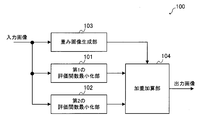
- FIG. 1 is a block diagram schematically showing the configuration of the image processing apparatus 100 according to the first embodiment.
- the image processing device 100 includes a first evaluation function minimization unit 101, a second evaluation function minimization unit 102, a weighted image generation unit 103, and a weight addition unit 104.
- the first evaluation function minimization unit 101 generates the first corrected image by correcting the blur included in the input image.
- the generated first corrected image is given to the weighted addition unit 104.
- the second evaluation function minimization unit 102 generates a second corrected image by correcting the blur included in the input image.
- the generated second corrected image is given to the weight addition unit 104.
- the first evaluation function minimization unit 101 and the second evaluation function minimization unit 102 treat the blur included in the input image as a deconvolution problem and correct the blur.
- the cause of the blur included in the input image is the blur (optical system blur) due to the optical system of the camera which is an imaging device for capturing the input image, or the camera moves when the input image is captured. There is blur (movement blur) etc.
- the input image may be referred to as a blurred image B. This is because the input image contains blur.
- the blurred image B can be modeled by the following equation (1), assuming that the latent image L including no blur is convoluted by a certain point image distribution function K and then the noise N is added.
- * represents a convolution operation.
- the deconvolution problem is that when the blurred image B and the point image distribution function K are given, the latent image L is obtained based on the model of the equation (1), or the blurred image B is given.
- This problem can be mathematically defined as an optimization problem, and is equivalent to finding a latent image L or a latent image L and a point image distribution function K that minimizes an appropriate evaluation function.
- C (L) consists of the sum of the fidelity term and the normalization term, and can be expressed by, for example, the following equation (2).
- w represents a constant and Ds represents a predetermined convolution kernel.
- p represents a norm of order p
- q represents a norm of order q.
- a value of 2 is often used as p and a value of 2 or less is used as q.
- the first term corresponds to the fidelity term.
- the fidelity term is a function that takes the minimum value when the relationship of equation (1) is established.
- the second term in the equation (2) corresponds to a normalization term.
- the normalization term is a term for imposing a certain limit on the solution of an optimization problem. For example, there are a plurality of latent images L that minimize the first term of the equation (2). Therefore, the solution of the optimization problem can be uniquely determined by imposing a certain limit on the latent image L according to the second term of the equation (2).
- ⁇ of the normalization term which is the second term of the equation (2), means that when a plurality of convolution kernels are used as Ds, the sum of the q-th order norms obtained for each convolution kernel is taken. To do.
- the optimization process of the formula (2) is described in detail in, for example, Japanese Patent Publication No. 2016-532367.
- the first evaluation function minimization unit 101 uses a kernel representing the first derivative of the image as Ds.
- the normalization term of the equation (2) becomes smaller as the change in the pixel value of the latent image L becomes smaller or as the latent image L becomes a flat image.
- the larger the number of edges or the gradation portion that monotonically increases or decreases in the latent image L the larger the normalization term of the equation (2) becomes.
- the latent image L becomes an image having poor edges or gradation.
- the evaluation function C (L) can be expressed by the following equation (3) when the kernel representing the first derivative is expressed in a matrix format.
- the first term corresponds to the first derivative in the vertical direction
- the second term corresponds to the first derivative in the horizontal direction.
- W1 represents a first constant corresponding to the constant w in the equation (3).
- the second evaluation function minimization unit 102 in the first embodiment uses a kernel representing the second derivative of the image as Ds.
- the normalization term of the equation (2) takes a small value not only when the change in the pixel value of the latent image L is small but also in the edge or the gradation portion.
- the latent image L is an image in which the change in the pixel value of the edge or the gradation portion is maintained.
- the flat portion in the image is not preserved as it is flat, and an edge-like pattern may appear unnaturally in the portion that should be originally flat.
- the second evaluation function minimization unit 102 is excellent in processing an area where the pixel value has a certain change such as an edge or a gradation, and the first evaluation function minimization unit 101 has a small change in the pixel value. It can be seen that the processing of the area is excellent.
- the evaluation function C (L) can be represented by the following equation (4) when the second-order differential kernel is represented in a matrix format.
- the first term is the vertical derivative
- the second term is the horizontal derivative
- the third term is the diagonal derivative.
- W2 represents a second constant corresponding to the constant w in the equation (4).
- the first evaluation function minimization unit 101 uses the first evaluation function, which becomes a higher evaluation value as the change in the pixel values of the plurality of pixels becomes smaller for the input image including the plurality of pixels.
- the function functions as a first correction processing unit that generates a first corrected image in which the blur of the input image is corrected.
- the first evaluation function is a function for obtaining an evaluation value including a value obtained by multiplying a term representing the magnitude of the first derivative of the input image by a constant (here, the first constant).
- the second evaluation function minimization unit 102 uses the second evaluation function, which becomes a higher evaluation value as the change in the pixel values of the plurality of pixels becomes larger with respect to the input image, to obtain a latent image from the input image. By asking for it, it functions as a second correction processing unit that generates a second corrected image in which the blur of the input image is corrected.
- the second evaluation function is a function for obtaining an evaluation value including a value obtained by multiplying a term representing the magnitude of the second derivative of the input image by a constant (here, the second constant).
- the weight image generation unit 103 determines the variation in the pixel value in the vicinity of each pixel for each pixel of the input image, and specifies the weight value so that the larger the variation in the pixel value, the larger the value. Is.
- the specified weight value is given to the weighted addition unit 104.
- the weight value is 0 or more and 1 or less.
- the weighted image generation unit 103 a case where the dispersion of the pixel values of the input image is used to determine the variation will be shown.
- the weighted image generation unit 103 first identifies each pixel included in the input image as a target pixel, defines a predetermined area including the target pixel, and calculates the variance of the pixel value in the area. To do. Next, the weighted image generation unit 103 maps the variance obtained for the target pixel of the input image to a value of 0 or more and 1 or less. As for the mapping result, the smaller the variance value, the closer to 0, and conversely, the larger the variance value, the closer to 1.
- the variance value ⁇ is set to m, which is a value of 0 or more and 1 or less, by the following equation (5). Can be mapped.
- the mapping method is not limited to the above equation (5), and the larger the value corresponding to the variation of the pixel value obtained in the vicinity of each pixel of the input image is larger than the predetermined threshold value, the closer to 1 and conversely. Anything smaller than a predetermined threshold value may be closer to 0.
- the above value of m can be calculated individually for each pixel of the input image. Therefore, if the value of m calculated individually for each pixel is regarded as the pixel value, the output of the weighted image generation unit 103 can be regarded as if it were an image. Therefore, hereinafter, the output of the weighted image generation unit 103 may be referred to as a weighted image. Further, the pixel value of the weighted image refers to the value of m calculated for each pixel of the input image. The value of m is also referred to as a weight value.
- the weighted addition unit 104 has a first correction image output from the first evaluation function minimization unit 101 and a second evaluation function minimization unit based on the pixel value of the weighted image output by the weight image generation unit 103. An output image that is the result of weighted addition to the second correction image output from 102 is generated.
- the weighted addition unit 104 increases the weight of the second corrected image with respect to the corresponding pixel value as the pixel value of the weighted image increases, and corresponds to the first corrected image as the pixel value of the weighted image decreases. Increase the weight for the pixel value to be used.
- the weight addition unit 104 uses the following equation.
- the value D3 calculated in (6) can be calculated as a pixel value of the output image.
- D1 is the corresponding pixel value of the first corrected image
- D2 is the corresponding pixel value of the second corrected image
- m is the corresponding pixel value (weight value) of the weighted image.
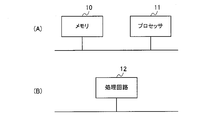
- FIG. 2A A part or all of the first evaluation function minimization unit 101, the second evaluation function minimization unit 102, the weight image generation unit 103, and the weight addition unit 104 described above are shown in FIG. 2A, for example.
- a processor 11 such as a CPU (Central Processing Unit) that executes a program stored in the memory 10.
- a program may be provided through a network, or may be recorded and provided on a recording medium. That is, such a program may be provided as, for example, a program product.
- the first evaluation function minimization unit 101 the second evaluation function minimization unit 102, the weight image generation unit 103, and the weight addition unit 104 are shown in FIG. 2B, for example.
- a processing circuit 12 such as a single circuit, a composite circuit, a programmed processor, a parallel programmed processor, an ASIC (Application Specific Integrated Circuit) or an FPGA (Field Programmable Gate Array).
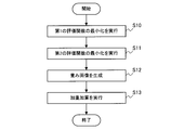
- FIG. 3 is a flowchart showing the operation of the image processing device 100 according to the first embodiment.
- an input unit which is an input device (not shown) of the image processing device 100 receives an instruction from the user. It is started in case etc.
- the first evaluation function minimization unit 101 uses the above equation (3) to generate a first corrected image in which the blur included in the input image is corrected (S10).
- the generated first corrected image is given to the weighted addition unit 104.
- the second evaluation function minimization unit 102 generates a second corrected image in which the blur included in the input image is corrected by using the above equation (4) (S11).
- the generated second corrected image is given to the weight addition unit 104.
- the weighted image generation unit 103 determines the variation in the pixel value in the vicinity of each pixel for each pixel of the input image, and specifies the weight value so that the larger the variation in the pixel value, the larger the value.
- a weighted image showing the specified weight value for each corresponding pixel is generated (S12). The generated weight image is given to the weight addition unit 104.
- the weight addition unit 104 has a first correction image output from the first evaluation function minimization unit 101 and a second evaluation function based on the pixel value of the weight image output by the weight image generation unit 103. An output image is generated as a result of weighted addition of the second correction image output from the minimization unit 102 (S13).
- the weight of the second corrected image becomes heavier at a place where the pixel value includes a certain change, such as an edge portion or a gradation portion of the input image, and conversely, the input image
- the weight of the first corrected image becomes heavier in the place where the change in the pixel value of is small. That is, for each pixel of the input image, the weight of the first evaluation function minimization unit 101 and the second evaluation function minimization unit 102 on the more suitable processing result increases.
- a pixel value suitable for each of a part where the pixel value changes to some extent such as an edge part or a gradation part of the input image and a part where the change in the pixel value of the input image is small is selected. Therefore, it is possible to obtain an output image with few artifacts such as jaggies.
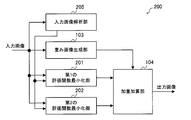
- FIG. 4 is a block diagram schematically showing the configuration of the image processing apparatus 200 according to the second embodiment.
- the image processing device 200 includes a first evaluation function minimization unit 201, a second evaluation function minimization unit 202, a weight image generation unit 103, a weight addition unit 104, and an input image analysis unit 205.
- the weighted image generation unit 103 and the weighted addition unit 104 in the second embodiment are the same as the weighted image generation unit 103 and the weighted addition unit 104 in the first embodiment.
- the constant w of the equation (2) described in the first embodiment is changed according to the characteristics of the input image.
- the constant w of the equation (2) is a value for adjusting the weight between the fidelity term and the normalization term, and the larger the value of the constant w, the larger the ratio of the normalization term to the equation (2).
- the latent image L has a lot of random noise. , The size of the normalization term increases. Therefore, the value calculated by the equation (2) also becomes large.
- both the first evaluation function minimization unit 201 and the second evaluation function minimization unit 202 obtain the latent image L that minimizes the magnitude of the value calculated by the equation (2), and thus correspond to the constant w.
- the values of the first constant w1 and the second constant w2 are increased, an image that does not include random noise is output as the latent image L.
- the latent image L from which the noise has been removed can be obtained by increasing the values of the first constant w1 and the second constant w2.
- the pixel values of fine patterns in the image which are called textures, change randomly, if the values of the first constant w1 and the second constant w2 are made larger than necessary, the texture will appear in the latent image L. It will be lost and an unnatural output image will be obtained.
- the values of the first constant w1 and the second constant w2 may be changed according to the amount of noise contained in the blurred image B, and when the amount of noise is small, the first constant w1 and the second constant w2 It is preferable to reduce the value of and increase the values of the first constant w1 and the second constant w2 when the amount of noise is large. By doing so, if the blurred image B contains a lot of noise, noise processing is appropriately performed, and conversely, if the blurred image B does not contain much noise, the texture is lost more than necessary. It is possible to perform blur correction without any noise.
- the configuration of the second embodiment will be described.
- the input image analysis unit 205 estimates the amount of noise contained in the blurred image B based on the input image, and the first constant w1 and the second constant w2 increase as the estimated noise amount increases. Determine the value.
- the determined first constant w1 is given to the first evaluation function minimization unit 201, and the second constant w2 is given to the second evaluation function minimization unit 202.
- the input image analysis unit 205 determines a predetermined first value as the first constant w1 and the second constant w2, and determines the noise.
- a predetermined second value is determined as the first constant w1 and the second constant w2.
- the first value is a value larger than the second value.
- the input image analysis unit 205 may determine the first constant w1 and the second constant w2 so as to increase monotonically with respect to the amount of noise.
- the noise amount can be defined by the S / N ratio obtained by dividing the signal amount by the variance of the noise amount.
- the signal amount is considered to be the brightness (pixel value).
- the input image analysis unit 205 extracts a representative value which is a representative value from the pixel value of the input image, and sets the extracted representative value as the signal amount S.
- the average value or the mode value of the pixel values in the input image can be used.
- the difference between the maximum value and the minimum value of the pixel values in the input image can be used as a representative value.
- the histogram distribution of the pixel values of the input image is aggregated, and the ones that occupy the predetermined ratios of the upper and lower pixel values are removed as outliers, and then the average value, the mode value, or the most frequent value, or , The difference between the maximum and minimum values can be used as a representative value.
- the S / N can be determined only by the signal amount S obtained as described above.
- the input image analysis unit 205 determines that the larger the value of the signal amount S, the smaller the noise amount, and the smaller the value of the signal amount S, the larger the noise amount. Then, the input image analysis unit 205 may increase the values of the first constant w1 and the second constant w2 as the amount of noise increases.
- the first evaluation function minimization unit 201 generates the first corrected image by correcting the blur included in the input image.
- the generated first corrected image is given to the weighted addition unit 104.
- the first evaluation function minimization unit 201 uses the first constant w1 given by the input image analysis unit 205, and the value represented by the above equation (3) is the minimum.
- the latent image L calculated so as to be the first corrected image is used.
- the second evaluation function minimization unit 202 generates a second corrected image by correcting the blur included in the input image.
- the generated second corrected image is given to the weight addition unit 104.
- the second evaluation function minimization unit 202 uses the second constant w2 given by the input image analysis unit 205, and the value represented by the above equation (4) is the minimum.
- the latent image L calculated so as to be the second corrected image is used.
- a part or all of the first evaluation function minimization unit 201, the second evaluation function minimization unit 202, the weight image generation unit 103, the weight addition unit 104, and the input image analysis unit 205 described above may be described, for example. As shown in FIG. 2A, it can be configured by the memory 10 and the processor 11. Such a program may be provided through a network, or may be recorded and provided on a recording medium. That is, such a program may be provided as, for example, a program product.
- first evaluation function minimization unit 201 the second evaluation function minimization unit 202, the weight image generation unit 103, the weight addition unit 104, and the input image analysis unit 205 are shown in FIG. As shown in B), it can also be configured by the processing circuit 12.
- FIG. 5 is a flowchart showing the operation of the image processing device 200 according to the second embodiment.
- an input unit which is an input device (not shown) of the image processing device 200 receives an instruction from the user. It is started in case etc.
- the input image analysis unit 205 estimates the amount of noise contained in the input image, and determines the values of the first constant w1 and the second constant w2 so that the larger the estimated noise amount, the larger the noise amount (1). S20).
- the determined first constant w1 is given to the first evaluation function minimization unit 201, and the second constant w2 is given to the second evaluation function minimization unit 202.
- the first evaluation function minimization unit 201 uses the first constant w1 given by the input image analysis unit 205 in the equation (3) to correct the blur included in the input image.
- An image is generated (S21).
- the generated first corrected image is given to the weighted addition unit 104.
- the second evaluation function minimization unit 202 uses the second constant w2 given by the input image analysis unit 205 in the equation (4) to correct the blur included in the input image.
- An image is generated (S22).
- the generated second corrected image is given to the weight addition unit 104.
- the weighted image generation unit 103 determines the variation in the pixel value in the vicinity of each pixel for each pixel of the input image, and specifies the weight value so that the larger the variation in the pixel value, the larger the value.
- a weighted image showing the specified weight value for each corresponding pixel is generated (S23). The generated weight image is given to the weight addition unit 104.
- the weight addition unit 104 has a first correction image output from the first evaluation function minimization unit 201 and a second evaluation function based on the pixel value of the weight image output by the weight image generation unit 103.
- An output image is generated as a result of weighted addition of the second correction image output from the minimization unit 202 (S24).
- the blur of the input image can be appropriately corrected according to the amount of noise of the input image.
- the effect in the second embodiment can be obtained. Although it becomes large, the effect in the second embodiment can be obtained only by changing only one of the first constant W1 in the equation (3) and the second constant W2 in the equation (4).
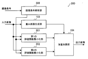
- FIG. 6 is a block diagram schematically showing the configuration of the image processing apparatus 300 according to the third embodiment.
- the image processing device 300 includes a first evaluation function minimization unit 301, a second evaluation function minimization unit 302, a weight image generation unit 103, a weight addition unit 104, and an imaging condition analysis unit 306.
- the weighted image generation unit 103 and the weighted addition unit 104 in the third embodiment are the same as the weighted image generation unit 103 and the weighted addition unit 104 in the first embodiment.
- the noise amount of the input image is estimated by analyzing the input image, but in the third embodiment, the noise amount of the input image is estimated from the imaging conditions of the input image.
- the imaging condition analysis unit 306 acquires imaging conditions from a camera as an imaging device that has captured an input image. Then, the imaging condition analysis unit 306 estimates the noise amount of the input image from the acquired imaging conditions. The imaging condition analysis unit 306 determines the values of the first constant w1 and the second constant w2 so that the larger the estimated noise amount is, the larger the value is. The determined first constant w1 is given to the first evaluation function minimization unit 301, and the second constant w2 is given to the second evaluation function minimization unit 302.
- the imaging condition analysis unit 306 determines a predetermined first value as a first constant w1 and a second constant w2, and determines the noise.
- a predetermined second value is determined as the first constant w1 and the second constant w2.
- the first value is a value larger than the second value.
- the imaging condition analysis unit 306 may determine the first constant w1 and the second constant w2 so as to increase monotonically with respect to the large amount of noise.
- the imaging condition analysis unit 306 takes an imaging time as an argument as an imaging condition, and determines that the longer the imaging time, the smaller the amount of noise. Then, the imaging condition analysis unit 306 determines the values of the first constant w1 and the second constant w2 so that the larger the amount of noise, the larger the first constant w1 and the second constant w2.
- the first evaluation function minimization unit 301 generates the first corrected image by correcting the blur included in the input image.
- the generated first corrected image is given to the weighted addition unit 104.
- the first evaluation function minimization unit 301 uses the first constant w1 given by the image pickup condition analysis unit 306, and the value represented by the above equation (3) is the minimum.
- the latent image L calculated so as to be the first corrected image is used.
- the second evaluation function minimization unit 302 generates a second corrected image by correcting the blur included in the input image.
- the generated second corrected image is given to the weight addition unit 104.
- the second evaluation function minimization unit 302 uses the second constant w2 given by the image pickup condition analysis unit 306, and the value represented by the above equation (4) is the minimum.
- the latent image L calculated so as to be the second corrected image is used.
- a part or all of the first evaluation function minimization unit 301, the second evaluation function minimization unit 302, the weight image generation unit 103, the weight addition unit 104, and the imaging condition analysis unit 306 described above may be described, for example. As shown in FIG. 2A, it can be configured by the memory 10 and the processor 11. Such a program may be provided through a network, or may be recorded and provided on a recording medium. That is, such a program may be provided as, for example, a program product.
- first evaluation function minimization unit 301 the second evaluation function minimization unit 302, the weight image generation unit 103, the weight addition unit 104, and the imaging condition analysis unit 306 are shown in FIG. As shown in B), it can also be configured by the processing circuit 12.
- FIG. 7 is a flowchart showing the operation of the image processing device 300 according to the third embodiment.
- an input unit which is an input device (not shown) of the image processing device 300 receives an instruction from the user. It is started in case etc.
- the imaging condition analysis unit 306 estimates the amount of noise contained in the input image, and determines the values of the first constant w1 and the second constant w2 so that the larger the estimated noise amount, the larger the noise amount (1). S30).
- the determined first constant w1 is given to the first evaluation function minimization unit 301, and the second constant w2 is given to the second evaluation function minimization unit 302.
- the first evaluation function minimization unit 301 uses the first constant w1 given by the imaging condition analysis unit 306 in the equation (3) to correct the blur included in the input image.
- An image is generated (S31).
- the generated first corrected image is given to the weighted addition unit 104.
- the second evaluation function minimization unit 302 uses the second constant w2 given by the imaging condition analysis unit 306 in the equation (4) to correct the blur included in the input image.
- An image is generated (S32).
- the generated second corrected image is given to the weight addition unit 104.
- the weighted image generation unit 103 determines the variation in the pixel value in the vicinity of each pixel for each pixel of the input image, and specifies the weight value so that the larger the variation in the pixel value, the larger the value.
- a weighted image showing the specified weight value for each corresponding pixel is generated (S33). The generated weight image is given to the weight addition unit 104.
- the weight addition unit 104 has a first correction image output from the first evaluation function minimization unit 301 and a second evaluation function based on the pixel value of the weight image output by the weight image generation unit 103.
- An output image is generated as a result of weighted addition of the second correction image output from the minimization unit 302 (S34).
- processing according to the amount of noise contained in the input image becomes possible. Specifically, if the input image contains a lot of noise, noise processing can be performed appropriately, and conversely, if the input image does not contain much noise, blur correction can be performed without losing texture more than necessary. It will be possible.
- the magnitudes of the first constant w1 and the second constant w2 are monotonously non-increasing with respect to the length of the imaging time when the input image is captured.
- the first evaluation function minimization unit 301 and the second evaluation function minimization unit 302 can be controlled so as to be.
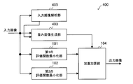
- FIG. 8 is a block diagram schematically showing the configuration of the image processing apparatus 400 according to the fourth embodiment.
- the image processing device 400 includes a first evaluation function minimization unit 101, a second evaluation function minimization unit 102, a weight image generation unit 403, a weight addition unit 104, and an input image analysis unit 405.
- the first evaluation function minimization unit 101, the second evaluation function minimization unit 102, and the weighted addition unit 104 in the fourth embodiment are the first evaluation function minimization unit 101, the second evaluation in the first embodiment. This is the same as the function minimization unit 102 and the weight addition unit 104.
- the first constant w1 and the second constant w2 are adjusted, whereas in the fourth embodiment, the threshold value ⁇ is adjusted instead of the first constant w1 and the second constant w2.
- the threshold value ⁇ is set to a large value, the number of pixels whose pixel value indicating the weight value is close to 0 increases in the weight image, and in the output image, the first correction image output from the first evaluation function minimization unit 101. Will occupy a large proportion.
- the threshold value ⁇ is set to a small value
- the number of pixels whose pixel value indicating the weight value is close to 1 increases in the weight image
- the second evaluation function minimization unit 102 outputs the output image.
- the ratio of the corrected image of is increased.
- the threshold value ⁇ is set to a large value, an output image having a higher effect of removing noise can be obtained from the weighted addition unit 104. Further, since the second corrected image is an image having excellent edge preservation, if the threshold value ⁇ is set to a small value, an output image in which edges are more preserved can be obtained from the weighted addition unit 104.
- the input image analysis unit 405 estimates the amount of noise contained in the blurred image B based on the input image, and determines the value of the threshold value ⁇ so that the larger the estimated amount of noise, the larger the amount of noise.
- the determined threshold value ⁇ is given to the weighted image generation unit 403.
- the method for estimating the amount of noise is the same as in the second embodiment.
- the input image analysis unit 405 determines a predetermined first value as the threshold value ⁇ , and the noise amount is larger than the predetermined threshold value. If it is small, a predetermined second value is determined as the threshold value ⁇ .
- the first value is a value larger than the second value.
- the input image analysis unit 405 may determine the threshold value ⁇ so as to increase monotonically with respect to the large amount of noise.
- the weighted image generation unit 403 determines the variation in the pixel value in the vicinity of each pixel for each pixel of the input image, and specifies the weight value so that the larger the variation in the pixel value, the larger the value.
- the specified weight value is given to the weighted addition unit 104.
- the weight image generation unit 403 calculates the weight value m by the above equation (5), and generates a weight image indicating the weight value m for each pixel.
- the weight image generation unit 403 calculates the weight value m using the threshold value ⁇ given by the input image analysis unit 405. Then, the generated weight image is given to the weight addition unit 104.
- FIG. 9 is a flowchart showing the operation of the image processing device 400 according to the fourth embodiment.
- an input unit which is an input device (not shown) of the image processing device 400 receives an instruction from the user. It is started in case etc.
- the input image analysis unit 405 estimates the amount of noise contained in the input image, and determines the value of the threshold value ⁇ so that the larger the estimated amount of noise, the larger the value (S40).
- the determined threshold value ⁇ is given to the weighted image generation unit 403.
- the first evaluation function minimization unit 101 generates a first corrected image in which the blur included in the input image is corrected by using the equation (3) (S41).
- the generated first corrected image is given to the weighted addition unit 104.
- the second evaluation function minimization unit 102 generates a second corrected image in which the blur included in the input image is corrected by using the equation (4) (S42).
- the generated second corrected image is given to the weight addition unit 104.
- the weighted image generation unit 403 determines the variation in the pixel value in the vicinity of each pixel for each pixel of the input image, and specifies the weight value so that the larger the variation in the pixel value, the larger the value.
- a weighted image showing the specified weight value for each corresponding pixel is generated (S43).
- the weight image generation unit 403 specifies the weight value by using the threshold value ⁇ given by the input image analysis unit 405.
- the generated weight image is given to the weight addition unit 104.
- the weight addition unit 104 has a first correction image output from the first evaluation function minimization unit 101 and a second evaluation function based on the pixel value of the weight image output by the weight image generation unit 403. An output image is generated as a result of weighted addition of the second correction image output from the minimization unit 102 (S44).
- the blur of the input image can be appropriately corrected according to the amount of noise of the input image.
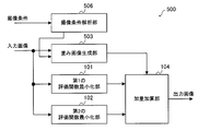
- FIG. 10 is a block diagram schematically showing the configuration of the image processing apparatus 500 according to the fifth embodiment.
- the image processing device 500 includes a first evaluation function minimization unit 101, a second evaluation function minimization unit 102, a weight image generation unit 503, a weight addition unit 104, and an imaging condition analysis unit 506.
- the first evaluation function minimization unit 101, the second evaluation function minimization unit 102, and the weighted addition unit 104 in the fifth embodiment are the first evaluation function minimization unit 101, the second evaluation in the first embodiment. This is the same as the function minimization unit 102 and the weight addition unit 104.
- the noise amount of the input image is estimated by analyzing the input image to determine the threshold value ⁇ , but in the fifth embodiment, the noise amount of the input image is determined by the imaging condition of the input image.
- the threshold value ⁇ is determined by estimating from.
- the imaging condition analysis unit 506 acquires imaging conditions from a camera as an imaging device that has captured an input image. Then, the imaging condition analysis unit 506 estimates the noise amount of the input image from the acquired imaging conditions. The method for estimating the amount of noise is the same as that in the third embodiment.
- the imaging condition analysis unit 506 determines the value of the threshold value ⁇ so that the larger the estimated noise amount, the larger the value.
- the determined threshold value ⁇ is given to the weighted image generation unit 503.
- the imaging condition analysis unit 506 determines a predetermined first value as the threshold value ⁇ , and the noise amount is larger than the predetermined threshold value. If it is small, a predetermined second value is determined as the threshold value ⁇ .
- the first value is a value larger than the second value.
- the imaging condition analysis unit 506 may determine the threshold value ⁇ so as to increase monotonically with respect to the large amount of noise.
- FIG. 11 is a flowchart showing the operation of the image processing device 500 according to the fifth embodiment.
- an input unit which is an input device (not shown) of the image processing device 500 receives an instruction from the user. It is started in case etc.
- the imaging condition analysis unit 506 estimates the amount of noise contained in the input image, and determines the value of the threshold value ⁇ so that the larger the estimated amount of noise, the larger the value (S50).
- the determined threshold value ⁇ is given to the weighted image generation unit 503.
- the first evaluation function minimization unit 101 generates a first corrected image in which the blur included in the input image is corrected by using the equation (3) (S51).
- the generated first corrected image is given to the weighted addition unit 104.
- the second evaluation function minimization unit 102 generates a second corrected image in which the blur included in the input image is corrected by using the equation (4) (S52).
- the generated second corrected image is given to the weight addition unit 104.
- the weighted image generation unit 503 determines the variation in the pixel value in the vicinity of each pixel for each pixel of the input image, and specifies the weight value so that the larger the variation in the pixel value, the larger the value.
- a weighted image showing the specified weight value for each corresponding pixel is generated (S53).
- the weighted image generation unit 503 specifies the weight value using the threshold value ⁇ given by the imaging condition analysis unit 506.
- the generated weight image is given to the weight addition unit 104.
- the weight addition unit 104 has a first correction image output from the first evaluation function minimization unit 101 and a second evaluation function based on the pixel value of the weight image output by the weight image generation unit 503. An output image is generated as a result of weighted addition of the second correction image output from the minimization unit 102 (S54).
- the fifth embodiment it is possible to perform processing according to the amount of noise contained in the input image. Specifically, if the input image contains a lot of noise, noise processing can be performed appropriately, and conversely, if the input image does not contain much noise, blur correction can be performed without losing texture more than necessary. It will be possible.
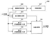
- FIG. 12 is a block diagram schematically showing the configuration of the image processing apparatus 600 according to the sixth embodiment.
- the image processing device 600 includes a first evaluation function minimization unit 101, a second evaluation function minimization unit 102, a weight image generation unit 603, a weight addition unit 104, an imaging condition analysis unit 606, and feature storage.
- a unit 607 is provided.
- the first evaluation function minimization unit 101, the second evaluation function minimization unit 102, and the weighted addition unit 104 in the sixth embodiment are the first evaluation function minimization unit 101, the second evaluation in the first embodiment. This is the same as the function minimization unit 102 and the weight addition unit 104.
- the ratio of the weighted addition in the weighted addition unit 104 can be determined from the information regarding the characteristics of the object shown in the input image, in other words, the imaged object.
- the object shown in the input image is specified by the imaging point which is the imaging point.
- the imaging point is specified by, for example, latitude and longitude
- the feature is determined by the topography of the imaging point with the latitude and longitude as arguments will be described.
- the latitude and longitude of the imaging point in imaging from the sky such as an aircraft-mounted camera, the latitude and longitude of the imaging point (in other words, the point captured by the camera) can be determined from the imaging plan in advance. In this case, the latitude and longitude and the imaging point If you have information (for example, a table) that associates with the terrain, you can determine the characteristics of the imaging point using latitude and longitude as arguments.
- the magnitude of the signal change included in the input image differs depending on whether the image is taken from the sky in a densely populated urban area of houses or buildings and in the case of a terrain with many natural objects such as desert or sea. ..
- the weighted addition unit 104 is more than the second evaluation function minimization unit 102.
- the weighted image generation unit 603 may adjust the weighted image so that the weighted to the second corrected image becomes large.
- the weighted addition unit 104 makes the first correction from the first evaluation function minimization unit 101.
- the weighted image generation unit 603 may adjust the weighted image so that the weight on the image becomes large. By doing so, it is possible to perform image processing more suitable for the subject or the imaging point.
- the feature storage unit 607 stores feature information indicating the features of the terrain corresponding to longitude and latitude.
- the feature information for example, a feature table which is table information in which the feature of the imaging point is associated with the longitude and the latitude may be used based on a prior imaging plan.
- the feature storage unit 607 can be configured by a non-volatile memory or a volatile memory.
- the imaging condition analysis unit 606 acquires imaging conditions from a camera as an imaging device that has captured an input image.
- the imaging conditions the longitude and latitude of the point where the input image is captured are acquired.
- the imaging condition analysis unit 606 identifies the feature corresponding to the acquired longitude and latitude from the feature information stored in the feature storage unit 607. It is assumed that the threshold value ⁇ is set in advance for the feature indicated by the feature information. Therefore, the imaging condition analysis unit 606 can determine the threshold value ⁇ corresponding to the specified feature. The determined threshold value ⁇ is given to the weighted image generation unit 603.
- the size of the threshold value ⁇ is made smaller than a predetermined value, and the second evaluation function minimization unit 102 is used.
- the weight of the corrected image of 2 may be set to a larger value.
- the size of the threshold value ⁇ is made larger than a predetermined value, and the first evaluation function minimization unit is used.
- the weight of the corrected image may be set to a larger value.
- the weighted image generation unit 603 determines the variation in the pixel value in the vicinity of each pixel for each pixel of the input image, and specifies the weight value so that the larger the variation in the pixel value, the larger the value.
- the specified weight value is given to the weighted addition unit 104.
- the weight image generation unit 603 calculates the weight value m according to the above equation (5), and generates a weight image indicating the weight value m for each pixel. Then, the generated weight image is given to the weight addition unit 104.
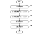
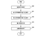
- FIG. 13 is a flowchart showing the operation of the image processing device 600 according to the sixth embodiment.
- an input unit which is an input device (not shown) of the image processing device 600 receives an instruction from the user. It is started in case etc.
- the imaging condition analysis unit 606 acquires the longitude and latitude of the point where the input image is captured by analyzing the metadata as the imaging condition of the input image (S61). Then, the imaging condition analysis unit 606 identifies the feature corresponding to the acquired longitude and latitude by referring to the feature information stored in the feature storage unit 607 (S62). The imaging condition analysis unit 606 gives the weighted image generation unit 603 a threshold value ⁇ corresponding to the specified feature.
- the feature here is the feature of the object to be imaged.
- the first evaluation function minimization unit 101 generates a first corrected image in which the blur included in the input image is corrected by using the equation (3) (S62).
- the generated first corrected image is given to the weighted addition unit 104.
- the second evaluation function minimization unit 102 generates a second corrected image in which the blur included in the input image is corrected by using the equation (4) (S63).
- the generated second corrected image is given to the weight addition unit 104.
- the weighted image generation unit 603 determines the variation in the pixel value in the vicinity of each pixel for each pixel of the input image, and specifies the weight value so that the larger the variation in the pixel value, the larger the value.
- a weighted image showing the specified weight value for each corresponding pixel is generated (S64).
- the weighted image generation unit 603 specifies the weight value by using the threshold value ⁇ given by the imaging condition analysis unit 606. The generated weight image is given to the weight addition unit 104.
- the weight addition unit 104 has a first correction image output from the first evaluation function minimization unit 101 and a second evaluation function based on the pixel value of the weight image output by the weight image generation unit 603. An output image is generated as a result of weighted addition of the second correction image output from the minimization unit 102 (S65).
- the sixth embodiment it is possible to perform processing according to the characteristics of the point where the input image is captured. Specifically, it is possible to perform blur correction according to the target captured by the input image.
- the threshold value ⁇ is determined according to the characteristics of the input image, but the sixth embodiment is not limited to such an example.
- the imaging condition analysis unit 606 may adjust the values of the first constant w1 and the second constant w2 according to the identified features. Specifically, when the specified feature indicates a place where there are many man-made objects such as an urban area, the first constant w1 and the second constant w2 are used in order to reproduce the edge-shaped part with emphasis. The value may be set to a value smaller than a predetermined value. On the contrary, when the specified feature indicates a terrain with many natural objects such as desert or sea, it is considered that there are few edge-shaped parts where the brightness changes rapidly, and conversely there are many flat parts. The values of the constant w1 and the second constant w2 may be set to a value larger than a predetermined value. Even in this case, only one of the first constant w1 and the second constant w2 may be changed.
- the sixth embodiment specifies the characteristics of the input image based on the longitude and the latitude
- the sixth embodiment is not limited to such an example.
- the weight value may be adjusted depending on whether the sea side is taken or the land side is taken. Specifically, when the land side is taken, it is expected that many artificial objects such as houses can be photographed, so it can be expected that many edge-shaped brightness changes can be seen there. Therefore, in such a case, in the weighted addition unit 104, the weighted image is generated by the weighted image generation unit 603 so that the weight from the second evaluation function minimizing unit 102 to the second corrected image becomes larger. You may adjust.
- the weighted image may be adjusted by the weighted image generation unit 603 so that the weighted image is larger.
- the feature information stored in the feature storage unit 607 may be associated with the longitude, the latitude, the imaging direction, and the feature.
Landscapes
- Engineering & Computer Science (AREA)
- Physics & Mathematics (AREA)
- General Physics & Mathematics (AREA)
- Theoretical Computer Science (AREA)
- Multimedia (AREA)
- Signal Processing (AREA)
- Image Processing (AREA)
Abstract
La présente invention comprend : une première unité de minimisation de fonction d'évaluation (101) qui génère une première image corrigée dans laquelle un flou d'une image d'entrée est corrigé, en utilisant une première fonction d'évaluation qui a une valeur d'évaluation plus élevée que le changement des valeurs de pixel d'une pluralité de pixels, pour une image d'entrée comprenant la pluralité de pixels, et en trouvant une image latente à partir de l'image d'entrée avant que le flou ait été inclus dans l'image d'entrée ; une seconde unité de minimisation de fonction d'évaluation (102) qui génère une seconde image corrigée dans laquelle le flou de l'image d'entrée est corrigé, en utilisant une seconde fonction d'évaluation qui a une valeur d'évaluation plus élevée que le changement de valeur de pixel pour la pluralité de pixels dans l'image d'entrée et en trouvant une image latente à partir de l'image d'entrée ; une unité d'identification de valeur de poids (103) qui identifie une valeur de pondération pour chaque pixel de la pluralité de pixels de telle sorte que le poids pour la seconde image corrigée augmente plus la variation de la valeur de pixel pour les pixels à l'intérieur d'une zone cible ; et une unité d'addition pondérée (104) qui utilise les valeurs de poids correspondant à chacun de la pluralité de pixels et effectue une addition pondérée de la première image corrigée et de la seconde image corrigée.
Priority Applications (2)
| Application Number | Priority Date | Filing Date | Title |
|---|---|---|---|
| JP2021525533A JP7146088B2 (ja) | 2019-06-14 | 2019-06-14 | 画像処理装置及び画像処理方法 |
| PCT/JP2019/023632 WO2020250412A1 (fr) | 2019-06-14 | 2019-06-14 | Dispositif de traitement d'image et procédé de traitement d'image |
Applications Claiming Priority (1)
| Application Number | Priority Date | Filing Date | Title |
|---|---|---|---|
| PCT/JP2019/023632 WO2020250412A1 (fr) | 2019-06-14 | 2019-06-14 | Dispositif de traitement d'image et procédé de traitement d'image |
Publications (1)
| Publication Number | Publication Date |
|---|---|
| WO2020250412A1 true WO2020250412A1 (fr) | 2020-12-17 |
Family
ID=73781590
Family Applications (1)
| Application Number | Title | Priority Date | Filing Date |
|---|---|---|---|
| PCT/JP2019/023632 Ceased WO2020250412A1 (fr) | 2019-06-14 | 2019-06-14 | Dispositif de traitement d'image et procédé de traitement d'image |
Country Status (2)
| Country | Link |
|---|---|
| JP (1) | JP7146088B2 (fr) |
| WO (1) | WO2020250412A1 (fr) |
Citations (2)
| Publication number | Priority date | Publication date | Assignee | Title |
|---|---|---|---|---|
| WO2014148074A1 (fr) * | 2013-03-18 | 2014-09-25 | 富士フイルム株式会社 | Dispositif et procédé de génération de filtre de restauration, dispositif et procédé de traitement d'image, appareil de capture d'image, programme, et support d'enregistrement |
| WO2016171087A1 (fr) * | 2015-04-23 | 2016-10-27 | 富士フイルム株式会社 | Dispositif de traitement d'image, appareil de capture d'image, procédé de traitement d'image, et programme de traitement d'image |
-
2019
- 2019-06-14 WO PCT/JP2019/023632 patent/WO2020250412A1/fr not_active Ceased
- 2019-06-14 JP JP2021525533A patent/JP7146088B2/ja active Active
Patent Citations (2)
| Publication number | Priority date | Publication date | Assignee | Title |
|---|---|---|---|---|
| WO2014148074A1 (fr) * | 2013-03-18 | 2014-09-25 | 富士フイルム株式会社 | Dispositif et procédé de génération de filtre de restauration, dispositif et procédé de traitement d'image, appareil de capture d'image, programme, et support d'enregistrement |
| WO2016171087A1 (fr) * | 2015-04-23 | 2016-10-27 | 富士フイルム株式会社 | Dispositif de traitement d'image, appareil de capture d'image, procédé de traitement d'image, et programme de traitement d'image |
Also Published As
| Publication number | Publication date |
|---|---|
| JPWO2020250412A1 (ja) | 2021-10-21 |
| JP7146088B2 (ja) | 2022-10-03 |
Similar Documents
| Publication | Publication Date | Title |
|---|---|---|
| Galdran | Image dehazing by artificial multiple-exposure image fusion | |
| CN113992861B (zh) | 一种图像处理方法及图像处理装置 | |
| US8358865B2 (en) | Device and method for gradient domain image deconvolution | |
| CN102905058B (zh) | 产生去除了重影模糊的高动态范围图像的设备和方法 | |
| CN108416754B (zh) | 一种自动去除鬼影的多曝光图像融合方法 | |
| Hee Park et al. | Gyro-based multi-image deconvolution for removing handshake blur | |
| US20170365046A1 (en) | Algorithm and device for image processing | |
| JP4999680B2 (ja) | 画像ノイズを低減することによる画像データ処理方法および該方法を実行するカメラ組み込み手段 | |
| Jia et al. | Bayesian correction of image intensity with spatial consideration | |
| JP4454657B2 (ja) | ぶれ補正装置及び方法、並びに撮像装置 | |
| KR102106537B1 (ko) | 하이 다이나믹 레인지 영상 생성 방법 및, 그에 따른 장치, 그에 따른 시스템 | |
| JP2013192224A (ja) | ブラー映像及びノイズ映像で構成されたマルチフレームを用いて非均一モーションブラーを除去する方法及び装置 | |
| JP7767338B2 (ja) | 画像処理方法、画像処理装置、画像処理システム、およびプログラム | |
| JPWO2016189901A1 (ja) | 画像処理装置、画像処理方法、プログラム、これを記録した記録媒体、映像撮影装置、及び映像記録再生装置 | |
| CN106375675B (zh) | 一种航空相机多曝光图像融合方法 | |
| Rabie | Adaptive hybrid mean and median filtering of high-ISO long-exposure sensor noise for digital photography | |
| JP6541454B2 (ja) | 画像処理装置、撮像装置、画像処理方法、画像処理プログラム、および、記憶媒体 | |
| Jin et al. | Image dehazing using non-local haze-lines and multi-exposure fusion | |
| KR101437898B1 (ko) | 단일 영상을 이용한 hdr 영상 생성 장치 및 방법 | |
| CN114866705A (zh) | 自动曝光方法、存储介质及电子设备 | |
| CN113034553B (zh) | 图像配准算法的评估方法、终端及存储介质 | |
| JP4859516B2 (ja) | 画像処理装置および画像復元方法 | |
| JP7146088B2 (ja) | 画像処理装置及び画像処理方法 | |
| KR101468433B1 (ko) | 결합된 색상 채널 변환 맵을 이용한 다이나믹 레인지 확장 장치 및 방법 | |
| Wang et al. | An airlight estimation method for image dehazing based on gray projection |
Legal Events
| Date | Code | Title | Description |
|---|---|---|---|
| 121 | Ep: the epo has been informed by wipo that ep was designated in this application |
Ref document number: 19932586 Country of ref document: EP Kind code of ref document: A1 |
|
| ENP | Entry into the national phase |
Ref document number: 2021525533 Country of ref document: JP Kind code of ref document: A |
|
| NENP | Non-entry into the national phase |
Ref country code: DE |
|
| 122 | Ep: pct application non-entry in european phase |
Ref document number: 19932586 Country of ref document: EP Kind code of ref document: A1 |