WO2014147833A1 - 歪測定装置、静電容量測定装置、歪測定方法、静電容量測定方法 - Google Patents
歪測定装置、静電容量測定装置、歪測定方法、静電容量測定方法 Download PDFInfo
- Publication number
- WO2014147833A1 WO2014147833A1 PCT/JP2013/058378 JP2013058378W WO2014147833A1 WO 2014147833 A1 WO2014147833 A1 WO 2014147833A1 JP 2013058378 W JP2013058378 W JP 2013058378W WO 2014147833 A1 WO2014147833 A1 WO 2014147833A1
- Authority
- WO
- WIPO (PCT)
- Prior art keywords
- electrode
- rod
- capacitance
- ground
- measuring
- Prior art date
- Legal status (The legal status is an assumption and is not a legal conclusion. Google has not performed a legal analysis and makes no representation as to the accuracy of the status listed.)
- Ceased
Links
Images


Classifications
-
- G—PHYSICS
- G01—MEASURING; TESTING
- G01B—MEASURING LENGTH, THICKNESS OR SIMILAR LINEAR DIMENSIONS; MEASURING ANGLES; MEASURING AREAS; MEASURING IRREGULARITIES OF SURFACES OR CONTOURS
- G01B7/00—Measuring arrangements characterised by the use of electric or magnetic techniques
- G01B7/16—Measuring arrangements characterised by the use of electric or magnetic techniques for measuring the deformation in a solid, e.g. by resistance strain gauge
- G01B7/22—Measuring arrangements characterised by the use of electric or magnetic techniques for measuring the deformation in a solid, e.g. by resistance strain gauge using change in capacitance
Definitions
- the present invention relates to a strain measuring device, a capacitance measuring device, a strain measuring method, and a capacitance measuring method.
- a strain measuring device that measures the amount of strain of a measurement object based on a capacitance value between a cylindrical electrode and a rod-like electrode is known (for example, Patent Document 1).
- the gap between the cylindrical electrode and the rod-shaped electrode is determined. Capacitance measurement accuracy may be reduced. For this reason, there exists a possibility that the measurement precision of the distortion amount of the to-be-measured object by a distortion measuring device may fall.
- the main present invention that solves the above-described problem has a cylindrical electrode that is disconnected from the ground, and the first electrode body that is attached to the object to be measured is disconnected from the ground.
- a cylindrical electrode inserted into the cylindrical electrode, connected to the second electrode body to be measured, the cylindrical electrode and the ground, and the cylindrical electrode and the cylindrical electrode;
- a first measurement unit that measures the capacitance between the second electrode, and the second measurement unit that measures the capacitance between the cylindrical electrode and the rod-shaped electrode by connecting the rod-shaped electrode and the ground;
- a third measuring unit for connecting the cylindrical electrode and the rod-shaped electrode, and measuring a capacitance between the cylindrical electrode and the ground; and a portion of the rod-shaped electrode inserted into the cylindrical electrode.
- the capacitance value between the cylindrical electrode and the rod-shaped electrode determined according to the length A strain that is calculated based on the measurement results of the first to third measuring sections and that measures the amount of strain in the direction in which the rod-shaped electrode is inserted in the object to be measured. It is a measuring device.
- FIG. 1 is a perspective view showing a part of the strain measuring apparatus in the present embodiment.
- the measurement cables 4A and 4B (FIG. 2) are omitted for convenience of explanation.
- the strain measuring device 900 is a device for measuring the amount of strain of a boiler, a turbine, a pipe, etc. provided in, for example, a thermal power plant.
- the strain measuring apparatus 900 is an apparatus for measuring the strain amount of the pipe 400 (measurement object), for example.
- the pipe 400 is a metal pipe that is provided in a thermal power plant and has a relatively high temperature of, for example, 600 ° C. or higher.
- the pipe 400 is formed by welding the first pipe 401 and the second pipe 402 in the longitudinal direction (X axis) of the pipe 400.
- the measurement target portion 403 which is a welded portion of the first pipe 401 and the second pipe 402 may be distorted due to deterioration over time due to creep or the like, for example.
- the strain measuring device 900 includes a first measuring device 100 (first electrode body), a second measuring device 200 (second electrode body), a switch device 5 (FIG. 4), and a third measuring device 6.
- the switch device 5 and the third measuring device 6 correspond to a first measuring unit, a second measuring unit, and a third measuring unit.
- the third measurement device 6 corresponds to a fourth measurement unit and a calculation unit.
- a configuration other than the first measurement device 100 and the second measurement device 200 in the strain measurement device 900 corresponds to the capacitance measurement device.
- the Z axis is an axis along the height direction (vertical direction) where the first measuring device 100 and the second measuring device 200 are erected, and + Z is the first measuring device 100 from the pipe 400.
- the X axis is an axis along the direction in which the first measuring device 100 and the second measuring device 200 are adjacent to each other, + X indicates the direction from the first measuring device 100 to the second measuring device 200, and ⁇ X is The direction from the second measuring device 200 toward the first measuring device 100 is indicated.
- the Y axis is an axis orthogonal to the X axis and the Z axis, + Y indicates a direction from one side surface to the other side surface of the first measuring device 100, and -Y indicates the first measuring device. The direction from the other side surface to the one side surface in 100 is shown.
- the first measuring device 100 and the second measuring device 200 measure the strain amount of the measurement target portion 403 in the metal pipe 400
- the first measurement device 100 and the second measurement device 200 are arranged on both sides of the measurement target portion 403 in the longitudinal direction (X axis) of the pipe 400. It is a device provided.
- the first measuring device 100 and the second measuring device 200 function as sensors for measuring the amount of strain in the longitudinal direction of the pipe 400 in the measurement target portion 403.
- the first measuring device 100 and the second measuring device 200 will be described later.
- the switch device 5 and the third measuring device 6 are capacitors formed by the first electrode 14 (cylindrical electrode) (FIG. 4) of the first measuring device 100 and the second electrode 24 (bar-shaped electrode) of the second measuring device 200. This is an apparatus that measures the capacitance of C0 and measures the strain amount of the pipe 400 based on the measurement result.
- the switch device 5 and the third measuring device 6 will be described later.
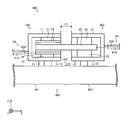
- FIG. 2 is a cross-sectional view showing a part of the strain measuring apparatus according to the present embodiment.
- FIG. 2 shows the first measurement device 100 and the second measurement device 200 in the state viewed from the XZ plane passing through the approximate center of the first measurement device 100 in FIG. 1 toward the + Y direction.
- FIG. 3 is a perspective view showing the first electrode and the second electrode in the present embodiment.
- the inside of the 1st electrode 14 is a state which cannot be seen, it is shown with the dotted line for convenience of explanation.
- the first measuring apparatus 100 is fixed to the first pipe 401 by welding, for example.
- the first measuring apparatus 100 includes a housing 11 (first case), legs 12 (first legs), a fixing member 13 (first support member), and a first electrode 14.
- the housing 11 is, for example, a metal housing for holding the first electrode 14 in a state where the first electrode 14 is accommodated.
- the outer shape of the housing 11 has, for example, a substantially rectangular column shape.
- the casing 11 has a hollow structure so that the first electrode 14 can be accommodated therein.
- the inner diameter of the housing 11 is made larger than the outer diameter of the first electrode 14 so that the first electrode 14 can be accommodated inside the housing 11.
- the casing 11 is welded to the first pipe 401 via the metal legs 12.
- the leg 12 protrudes from the housing 11 toward the first piping 401 between the first piping 401 and the housing 11 and is fixed to the first piping 401.
- the fixing member 13 is an insulating member such as ceramics for fixing the first electrode 14 inside the housing 11.
- the fixing member 13 supports the first electrode 14 so that the first electrode 14 does not contact the housing 11 inside the housing 11. That is, the first electrode 14 and the ground are interrupted.
- the first electrode 14 is a metal member for forming the capacitor C0 (FIG. 4) together with the second electrode 24. That is, the first electrode 14 functions as one of the two electrodes in the capacitor C0.
- the first electrode 14 extends in a rod shape along the longitudinal direction (X axis) of the pipe 400.
- the external shape of the 1st electrode 14 exhibits elongate cylindrical shape, for example.
- the first electrode 14 is provided with an insertion hole 14A so that the second electrode 24 can be inserted and retracted therein, and has a hollow structure. That is, the first electrode 14 has a cylindrical shape.
- the value of the capacitance of the capacitor C0 with respect to the distance G1 between the first measuring device 100 and the second measuring device 200 in the longitudinal direction of the pipe 400 changes according to the value of the distance G1.
- a cylindrical shape is used inside the first electrode 14.
- Second measuring device The second measuring device 200 is fixed to the second pipe 402 by, for example, welding.
- the second measuring apparatus 200 includes a casing 21 (second case), legs 22 (second legs), a fixing member 23 (second support member), and a second electrode 24.
- the housing 21 is, for example, a metal housing for holding the second electrode 24 in a state where the second electrode 24 is accommodated.
- the outer shape of the housing 21 has, for example, a substantially rectangular column shape.
- the casing 21 has a hollow structure so that the second electrode 24 can be accommodated therein.
- the inner diameter of the housing 21 is larger than the outer diameter of the second electrode 24 so that the second electrode 24 can be accommodated inside the housing 21.
- the casing 21 is welded to the second pipe 402 via the metal legs 22.
- the leg 22 protrudes from the housing 21 toward the second piping 402 between the second piping 402 and the housing 21 and is fixed to the second piping 402.
- the fixing member 23 is an insulating member such as ceramics for fixing the second electrode 24 inside the housing 21.
- the fixing member 23 supports the second electrode 24 so that the second electrode 24 does not contact the casing 21 inside the casing 21. That is, the second electrode 24 and the ground are interrupted.
- the second electrode 24 is a metal member for forming the capacitor C0 (FIG. 4) together with the first electrode 14. That is, the second electrode 24 functions as the other electrode of the two electrodes in the capacitor C0.
- the second electrode 24 extends in a rod shape along the longitudinal direction (X axis) of the pipe 400.
- the outer shape of the second electrode 24 has, for example, a cylindrical shape.
- the end 24A of the second electrode 24 is inserted into the insertion hole 14A of the first electrode 14.
- the second electrode 24 is inserted into the insertion hole 14 ⁇ / b> A so as not to contact the first electrode 14.
- the outer surface of the end 24A (hereinafter also referred to as “insertion portion of the second electrode 24”) of the second electrode 24 inserted into the first electrode 14 is the first electrode 14 in the insertion hole 14A. It will face the inner surface of the.
- the insertion portion of the second electrode 24 functions as the other electrode of the capacitor C0, and a part of the first electrode 14 facing the insertion portion of the second electrode 24 (hereinafter referred to as “opposing portion of the first electrode 14”). Will also function as one electrode of the capacitor C0.
- the value of the capacitance of the capacitor C0 is determined according to the area of the insertion portion of the second electrode 24 and the area of the facing portion of the first electrode 14. That is, the value of the capacitance of the capacitor C0 is determined according to the distance G1 between the first measuring device 100 and the second measuring device 200 in the longitudinal direction of the pipe 400.
- the capacitance value of the capacitor C0 (FIG. 4) formed by the first electrode 14 and the second electrode 24 is the value of the first measuring device 100 and the second measuring device 200 in the longitudinal direction (X axis) of the pipe 400. It is determined according to the distance G1 between them. That is, the value of the capacitance of the capacitor C0 is determined according to the length of the portion of the second electrode 24 inserted into the first electrode 14.
- the length of the portion inserted into the first electrode 14 at the end 24A of the second electrode 24 decreases. Therefore, as the distance G1 increases, the area of the insertion portion of the second electrode 24 and the area of the facing portion of the first electrode 14 become narrower. That is, the area of one electrode and the area of the other electrode in the capacitor C0 are reduced, and the capacitance value of the capacitor C0 is reduced.
- the distance G1 becomes shorter, the length of the portion inserted into the first electrode 14 at the end 24A of the second electrode 24 becomes longer. Therefore, as the distance G1 becomes shorter, the area of the insertion portion of the second electrode 24 and the area of the facing portion of the first electrode 14 become wider. That is, the area of one electrode and the area of the other electrode in the capacitor C0 are increased, and the capacitance value of the capacitor C0 is increased.
- the fluctuation range of the distance G1 can be obtained based on the fluctuation range of the capacitance value of the capacitor C0. That is, based on the fluctuation range of the capacitance value of the capacitor C0, it is possible to obtain the amount of distortion in the direction (X axis) in which the second electrode 24 in the measurement target portion 403 is inserted into the first electrode 14. .
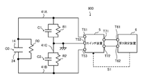
- FIG. 4 is a circuit diagram showing an equivalent circuit of the strain measuring apparatus in the present embodiment.
- the capacitor C0 is a capacitor formed by the first electrode 14 and the second electrode 24, for example.
- the capacitor C1 has a parasitic capacitance between the first electrode 14 and the pipe 400 (earth), and a capacitance between the conductive line 41A (first conductive line) and the pipe 400 (conductive line 42A, ground).
- the capacitor C2 has a parasitic capacitance between the second electrode 24 and the pipe 400 (earth), and a capacitance between the conductive line 41B (second conductive line) and the pipe 400 (conductive line 42B, ground). Show. Note that the pipe 400 is grounded. That is, the pipe 400 is connected to the ground.
- the insulation resistance R0 indicates, for example, the insulation resistance between the first electrode 14 and the second electrode 24.
- the insulation resistance R1 indicates, for example, an insulation resistance between the first electrode 14 and the pipe 400 and an insulation resistance between the conductive wire 41A and the pipe 400.
- the insulation resistance R2 indicates, for example, an insulation resistance between the second electrode 24 and the pipe 400 and an insulation resistance between the conductive wire 41B and the pipe 400.
- the conductive wire 41C includes the conductive wire 42A (third conductive wire) of the measurement cable 4A (FIG. 2), the conductive wire 42B (third conductive wire) of the measurement cable 4B, the casings 11, 21, legs 12, 22, and the piping 400. Is shown.
- the conductive wire 42A of the measurement cable 4A (FIG. 2), the conductive wire 42B of the measurement cable 4B, the casings 11, 21, legs 12, 22, and the pipe 400 are connected to each other, and the pipe 400 is connected to the ground. Therefore, the conductive wire 51C also corresponds to the ground.
- the measurement cables 4A and 4B are, for example, coaxial cables.
- the conductive wires 41A and 41B indicate the inner conductors of the measurement cables 4A and 4B, respectively, and the conductive wires 42A and 42B indicate the outer conductors of the measurement cables 4A and 4B, respectively.
- one end of each of the conductive wires 42A and 42B is connected to the housings 11 and 21, for example, relatively firmly, but in FIG. 2, it is connected at one point for convenience of explanation. It is shown.
- the switch device 5 is a device that switches connection destinations between the first measuring device 100 and the second measuring device 200 and the third measuring device 6.
- the switch device 5 includes a first terminal T51, a second terminal T52, a third terminal T53, a fourth terminal T71, and a fifth terminal T72 (hereinafter also referred to as “each terminal of the switch device 5”).
- the other end of the conductive wire 41A is connected to the first terminal T51. Note that one end of the conductive wire 41A is connected to the first electrode 14 as described above.
- a conductive line 41C is connected to the second terminal T52. That is, for example, the other end of the conductive wire 42A in the measurement cable 4A is connected to the second terminal T52. Note that one end of the conductive wire 42A is connected to the housing 11 as described above.
- the other end of the conductive wire 41B is connected to the third terminal T53. Note that one end of the conductive wire 41B is connected to the second electrode 24 as described above.
- a connector for connecting the above-described conductive wire to the first terminal T51, the second terminal T52, and the third terminal T53 is provided, and the first terminal T51, Conductive wires may be connected to the second terminal T52 and the third terminal T53.
- the fourth terminal T71 and the fifth terminal T72 are connected to the first terminal T61 and the second terminal T62 of the third measuring device 6, respectively.
- the third measuring device 6 will be described later.
- the switch device 5 Based on the control signal S1 from the third measuring device 6, the switch device 5 connects the first terminal T51, the second terminal T52, and the third terminal T53 to one of the fourth terminal T71 and the fifth terminal T72, respectively. .
- the first terminal T51, the second terminal T52, and the third terminal T53 are respectively set to the fourth terminal T71 and the fifth terminal T72 based on the control signal S1 from the third measuring device 6. It is assumed that a switch circuit (not shown) for connection to one of the two is provided. The switch circuit will be described later.
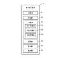
- FIG. 5 is a block diagram showing functions of the third measuring apparatus in the present embodiment.
- the third measuring device 6 is a device that measures the distortion amount of the measurement target portion 403 based on the capacitance value of the capacitor C0.
- the third measuring device 6 controls the switch device 5 and measures the capacitance of the capacitor C0.
- the third measuring device 6 includes a transmission unit 61, a measurement unit 62, a storage unit 63, a calculation unit 64, a display unit 65, and a control unit 66.
- the transmission unit 61 transmits a control signal S1 to the switch device 5.
- the control signal S ⁇ b> 1 is a signal for controlling the switch circuit of the switch device 5. It is assumed that the third measuring device 6 is connected to the switch device 5 via, for example, a communication cable (not shown) so that the transmission unit 61 can transmit the control signal S1 to the switch device 5.
- the measuring unit 62 measures the capacitance of the capacitor C0.
- the measuring unit 62 will be described later.
- the storage unit 63 includes, for example, a first area 631, a second area 632, and a third area 633.
- a first program for controlling the measuring device 6 and a second program for controlling the switch device 5 are stored.
- first measurement information for example, first measurement information, second measurement information, and third measurement information indicating measurement results of the measurement unit 62 are stored.
- the first measurement information, the second measurement information, and the third measurement information will be described later.
- the third area 633 information for calculating the distortion amount of the measurement target portion 403 is stored.
- the calculation unit 64 calculates the distortion amount of the measurement target portion 403 based on the first measurement information, the second measurement information, and the third measurement information. That is, the calculation unit 64 calculates the distortion amount of the measurement target portion 403 based on the measurement result of the measurement unit 62.
- the display unit 65 is, for example, a monitor that displays the calculation result of the calculation unit 64 and the like.
- the control unit 66 controls the measuring device 6 based on the first program. Further, the control unit 66 outputs a control signal S1 from the transmission unit 61 based on the second program. Specifically, the control unit 66 outputs, from the transmission unit 61, a control signal S1 (hereinafter also referred to as “first control signal”) that sets each terminal of the switch device 5 to the first connection state (FIG. 6). A control signal S1 for setting each terminal of the switch device 5 to the second connection state (hereinafter also referred to as “second control signal”) is output from the transmitter 61, or each terminal of the switch device 5 is set to the third connection state. Control signal S ⁇ b> 1 (hereinafter also referred to as “third control signal”) to be output from the transmission unit 61.
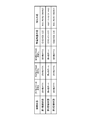
- FIG. 6 is a diagram illustrating a measurement result of the third measuring device with respect to the connection state of the terminals of the switch device according to the present embodiment.
- the switch circuit sets the first terminal T51, the second terminal T52, and the third terminal T53 to the fourth terminal T71 or the fifth terminal T72 based on the control signal S1 from the third measuring device 6, respectively. It is a circuit for connecting to any one of them.
- the first connection state is a state in which the first terminal T51, the second terminal T52, and the third terminal T53 are connected to the fourth terminal T71, the fourth terminal T71, and the fifth terminal T72, respectively. That is, in the first connection state, the first terminal T51 and the second terminal T52 are both connected to the fourth terminal T71 and short-circuited. In the first connection state, the third terminal T53 is electrically insulated from the first terminal T51 and the second terminal T52.
- the first electrode 14 is connected to the ground (conductive wire 41C) via the conductive wire 41A and the switch device 5, and is also connected to the first terminal T61 of the third measuring device 6. It will be.
- the second electrode 24 is connected to the second terminal T62 of the third measuring device 6 via the conductive wire 41B and the switch 5.
- the second connection state is a state in which the first terminal T51, the second terminal T52, and the third terminal T53 are connected to the fourth terminal T71, the fifth terminal T72, and the fourth terminal T71, respectively. That is, in the second connection state, the first terminal T51 and the third terminal T53 are both connected to the fourth terminal T71 and short-circuited.
- the second terminal T52 is electrically insulated from the first terminal T51 and the third terminal T53. Therefore, in the second connection state, the first electrode 14 is connected to the second electrode 24 via the conductive wire 41A and the switch device 5 and to the first terminal T61 of the third measuring device 6. Become. Further, in the second connection state, the second terminal T62 of the third measuring device 6 is connected to the ground (conductive wire 41C) via the switch 5.
- the third connection state is a state in which the first terminal T51, the second terminal T52, and the third terminal T53 are connected to the fourth terminal T71, the fifth terminal T72, and the fifth terminal T72, respectively. That is, in the third connection state, both the second terminal T52 and the third terminal T53 are connected to the fifth terminal T72 and are short-circuited.
- the first terminal T51 is electrically insulated from the second terminal T52 and the third terminal T53.
- the second electrode 24 is connected to the ground (conductive wire 41C) via the conductive wire 41B and the switch device 5, and is also connected to the second terminal T62 of the third measuring device 6. It will be.
- the first electrode 24 is connected to the first terminal T61 of the third measuring device 6 through the conductive wire 41A and the switch 5.
- the measuring unit 62 measures the capacitance of the capacitor C0.
- the measuring unit 62 may be a function realized by an LCR meter or the like.
- the measuring unit 62 is connected between the first terminal T61 and the second terminal T62 of the third measuring device 6 and the capacitance of the capacitor connected between the first terminal T61 and the second terminal T62. The resistance value of the electrical resistance is measured, and information indicating the measurement result is stored in the second region 632.
- first terminal T61 and the second terminal T62 are terminals provided in the third measuring device 6.
- the first terminal T61 and the second terminal T62 are connected to the fourth terminal T71 and the fifth terminal T72 of the switch device 5, respectively.
- the first terminal 61 is, for example, a terminal for applying an AC voltage.
- the first terminal 61 also functions as a terminal for applying (outputting) a current flowing through the conductive wire 41A based on, for example, a capacitor and electrical resistance provided between the first terminal T61 and the second terminal T62. .
- the second terminal 62 is a terminal for detecting, for example, a current passing through a capacitor and an electrical resistor provided between the first terminal T61 and the second terminal T62 by an applied voltage.
- the second terminal 62 is a terminal for applying an AC voltage, for example, and the first terminal 61 is placed between the first terminal T61 and the second terminal T62 by the applied voltage, for example. It is good also as a terminal for detecting the electric current which passed the capacitor and electric resistance which were provided.
- the measuring unit 62 for example, based on the voltage output from the first terminal T61 and the current detected at the second terminal T62, the capacitance of the capacitor provided between the first terminal T61 and the second terminal T62. Measure resistance values of capacitance and electrical resistance.
- the measuring unit 62 is a capacitor provided between the first terminal T61 and the second terminal T62 based on, for example, the voltage output from the second terminal T62 and the current detected at the first terminal T61. It is good also as measuring the resistance value of an electrostatic capacitance and an electrical resistance.
- the capacitor whose capacitance is measured by the measuring unit 62 and the electrical resistance whose resistance value is measured are selected according to the connection state of each terminal of the switch device 5.
- the capacitance of a predetermined capacitor and the resistance value of a predetermined electric resistance are selectively measured according to the connection state of each terminal of the switch device 5.
- the capacitors C0 and C2 are connected in parallel between the first terminal T61 and the second terminal T62.
- the insulation resistances R0 and R1 are further connected in parallel between the first terminal T61 and the second terminal T62. That is, when each terminal of the switch device 5 is in the first connection state, the measurement unit 62 includes the combined capacitor C10 when the capacitors C0 and C2 are connected in parallel to each other and the insulation resistors R0 and R1 connected in parallel to each other. The combined resistance R10 when measured is measured. Then, the measurement unit 62 stores information indicating the capacitance value C10 and the resistance value R10 in the second region 632 as first measurement information.
- the capacitance values of the combined capacitors C10, C20, and C30 are also referred to as capacitance values C10, C20, and C30, respectively.
- the resistance values of the combined resistors R10, R20, and R30 are also referred to as resistance values R10, R20, and R30, respectively.
- the capacitance values of the capacitors C0, C1, and C2 are also referred to as capacitance values C0, C1, and C2, respectively.
- the resistance values of the insulation resistances R0, R1, and R2 are also referred to as resistance values R0, R1, and R2, respectively.
- the capacitors C1 and C2 are connected in parallel between the first terminal T61 and the second terminal T62.
- the insulation resistors R1 and R1 are further connected in parallel between the first terminal T61 and the second terminal T62. That is, when each terminal of the switch device 5 is in the second connection state, the measurement unit 62 includes the combined capacitor C20 when the capacitors C1 and C2 are connected in parallel to each other and the insulation resistances R1 and R2 connected in parallel to each other. The combined resistance R20 when measured is measured. Then, the measurement unit 62 stores information indicating the capacitance value C20 and the resistance value R20 in the second region 632 as second measurement information.
- the capacitors C1 and C0 are connected in parallel between the first terminal T61 and the second terminal T62.
- the insulation resistances R1 and R0 are further connected in parallel between the first terminal T61 and the second terminal T62. That is, when each terminal of the switch device 5 is in the second connection state, the measurement unit 62 includes the combined capacitor C30 when the capacitors C1 and C0 are connected in parallel to each other and the insulation resistors R1 and R0 are connected in parallel to each other. The combined resistance R203 when measured is measured. Then, the measurement unit 62 stores information indicating the capacitance value C30 and the resistance value R30 in the second region 632 as third measurement information.
- the calculation unit 64 calculates the distortion amount of the measurement target portion 403 based on the first measurement information, the second measurement information, and the third measurement information stored in the second region 632.
- Capacitance value and resistance value The computing unit 64 calculates capacitance values C0, C1, and C2 based on the first measurement information, the second measurement information, and the third measurement information. This calculation is performed based on a relatively simple and simple calculation. In addition, the calculation unit 64 calculates resistance values R0, R1, and R2 based on the first measurement information, the second measurement information, and the third measurement information. This calculation is performed based on a relatively simple calculation.
- the computing unit 64 calculates the capacitance value of the capacitor C0 based on the capacitance value C0 and information stored in the third region 633, and calculates the distortion amount of the measurement target portion 403. .
- the computing unit 64 starts from the first time based on the value of the capacitance of the capacitor C0 at the first time and the value of the capacitance of the capacitor C0 at the second time after the first time.
- a distortion amount of the measurement target portion 403 in a predetermined time (predetermined period) until the second time is calculated.
- the calculation unit 64 calculates the distortion amount of the measurement target portion 403 based on the difference between the capacitance value of the capacitor C0 at the first time and the capacitance value of the capacitor C0 at the second time.
- information in which the fluctuation range of the capacitance value of the capacitor C0 and the distortion amount of the measurement target portion 403 are associated with each other is stored in advance.
- the third area 633 may store information in which the capacitance value of the capacitor C0 and the distortion amount of the measurement target portion 403 are associated with each other.
- the calculation unit 64 outputs the distortion amount of the measurement target portion 403 corresponding to the capacitance value C0 based on the information stored in the third region 633.
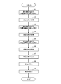
- FIG. 7 is a flowchart showing the operation of the third measuring apparatus in the present embodiment.
- the third measuring device 6 outputs a first control signal. Each terminal of the switch device 5 is in the first connection state.
- the third measuring device 6 measures the combined capacitance C10 of the capacitor connected between the first terminal T61 and the second terminal T62 (step St1).
- the third measuring device 6 stores first measurement information indicating the measurement result of the combined capacitance C10 in the second region 632 (Step St2).
- the third measuring device 6 outputs a second control signal. Each terminal of the switch device 5 is in the second connection state.
- the third measuring device 6 measures the combined capacitance C20 of the capacitor connected between the first terminal T61 and the second terminal T62 (step St3).
- the third measuring device 6 stores second measurement information indicating the measurement result of the combined capacitance C20 in the second region 632 (Step St4).
- the third measuring device 6 outputs a third control signal. Each terminal of the switch device 5 is in the third connection state.
- the third measuring device 6 measures the combined capacitance C30 of the capacitor connected between the first terminal T61 and the second terminal T62 (step St5).
- the third measuring device 6 stores third measurement information indicating the measurement result of the combined capacitance C30 in the second region 632 (Step St6).
- the third measuring device 6 calculates capacitance values C0, C1, and C2 based on the first measurement information, the second measurement information, and the third measurement information (step St7).
- the third measuring device 7 calculates the distortion amount of the measurement target portion 403 based on the capacitance value C0 and information stored in the third region 633 (step St8).
- the third measuring apparatus 6 performs the above-described steps St1 to St7 at both the first time and the second time, and the capacitance values C0, C1, C2, and the second at the first time. Both capacitance values C0, C1, and C2 at the time may be calculated. Then, the third measuring device 6 determines the predetermined time from the first time to the second time based on the difference between the capacitance value C0 at the first time and the capacitance value C0 at the second time. The amount of distortion of the measurement target portion 403 in time (predetermined period) may be calculated.
- the third measuring device 7 displays the calculation result in step St8 on, for example, the display unit 65 (step St9).
- the strain measuring device 900 includes the first measuring device 100, the second measuring device 200, the switch device 5, and the third measuring device 6.
- the first measuring device 100 has a first electrode 14 that is disconnected from the ground, and is attached to the pipe 400.
- the second measuring device 200 has a second electrode 24 that is cut off from the ground and inserted into the first electrode 14, and is attached to the pipe 400.
- the third measuring device 6 measures the combined capacitance C10 between the first electrode 14 (ground) and the second electrode 24.
- the switch device 5 connects the second electrode 24 and the ground
- the third measuring device 6 measures the combined capacitance C30 between the second electrode 24 (ground) and the first electrode 14.
- the third measuring device 6 measures the combined capacitance C20 between the first electrode 14 (second electrode 24) and the ground.
- the third measuring device 6 calculates the capacitance value C0 of the capacitor C0 based on the capacitance values of the combined capacitors C10, C20, and C30, and the direction in which the second electrode 24 in the pipe 400 is inserted ( The amount of strain on the X axis) is measured.
- the capacitance value C0 of the capacitor C0 is determined according to the length of the portion of the second electrode 24 inserted into the first electrode 14.
- the measurement error of the capacitance of the capacitor C0 based on the capacitance of the capacitor C1 and the capacitance of the capacitor C2 can be reduced. That is, in the strain measuring apparatus 900, by improving the measurement accuracy of the capacitance of the capacitor C0, the measurement accuracy of the strain amount of the pipe 400 in the direction in which the second electrode 24 is inserted (X axis) is improved. Can do.
- the first measuring device 100 includes a housing 11 and a fixing member 13.
- the casing 11 is a metal casing that is attached to the pipe 400 and connected to the ground in a state of surrounding the first electrode 14 so that the second electrode 24 is inserted into the first electrode 14.
- the fixing member 13 is an insulating member that supports the first electrode 14 inside the housing 11 so that the first electrode 14 does not contact the housing 11 inside the housing 11.
- the second measuring apparatus 200 includes a housing 21 and a fixing member 23.
- the casing 21 is a metal casing that is attached to the pipe 400 and connected to the ground in a state of surrounding the second electrode 24 so that the second electrode 24 is inserted into the first electrode 14.
- the fixing member 23 is an insulating member that supports the second electrode 24 inside the housing 21 so that the second electrode 24 does not contact the housing 21 inside the housing 21.
- the strain measuring apparatus 900 includes conductive wires 41A, 41B, 42A, and 42B.
- the conductive line 41 ⁇ / b> A is connected to the first electrode 14.
- the conductive line 41B is connected to the second electrode 24.
- the conductive wire 42 ⁇ / b> A is connected to the housing 11.
- the conductive wire 42B is connected to the housing 21.
- the switch device 5 connects the first electrode 14 and the ground by connecting the conductive wire 41A and the conductive wires 42A and 42B.
- the third measuring device 6 measures the combined capacitance C10 between the conductive line 41A and the conductive lines 42A and 42B.
- the switch device 5 connects the second electrode 24 and the ground by connecting the conductive wire 41B and the conductive wires 42A and 42B.
- the third measuring device 6 measures the combined capacitance C30 between the conductive line 41B and the conductive lines 42A and 42B.
- the switch device 5 connects the first electrode 14 and the second electrode 24 by connecting the conductive line 41A and the conductive line 41B.
- the third measuring device 6 measures the combined capacitance C20 between the conductive lines 41A and 41B and the conductive lines 42A and 42B.
- the strain amount of the pipe 400 can be measured using the conductive wires 41A, 41B, 42A, and 42B. That is, it is possible to provide an easy-to-use strain measuring apparatus 900 that can measure the strain amount of the pipe 400 at a position distant from the pipe 400 that is relatively high in temperature, such as 600 ° C. or higher. Further, the measurement error of the capacitance of the capacitor C0 based on the capacitance between the conductive wires 41A and 42A and the capacitance between the conductive wires 41B and 42B can be reduced. That is, in the strain measuring apparatus 900, the measurement accuracy of the strain amount of the pipe 400 in the direction in which the second electrode 24 is inserted can be improved by improving the measurement accuracy of the capacitance of the capacitor C0.
- the first measuring apparatus 100 further has metal legs 12 that protrude from the casing 11 toward the pipe 400 between the pipe 400 and the casing 11 and are fixed to the pipe 400.
- the second measuring apparatus 200 further has a metal leg 22 that is fixed to the pipe 400 and protrudes from the casing 21 toward the pipe 400 between the pipe 400 and the casing 21.
- the pipe 400 includes a first pipe 401 and a second pipe 402 connected to the first pipe 401.
- the legs 12 and 22 are fixed to the first pipe 401 and the second pipe 402, respectively. Therefore, the strain measuring apparatus 900 can measure the strain amount of the pipe 400 according to the strain of the measurement target portion 403 such as a welded portion, for example.
- the calculation unit 64 in which the first measurement information, the second measurement information, and the third measurement information indicating the measurement result of the measurement unit 62 are stored is the first measurement information and the second measurement information. Based on the third measurement information, the distortion amount of the measurement target portion 403 is calculated.
- the switch device 5 and the third measuring device 6 measure the capacitance of the capacitor C0 in the strain measuring device 900.
- the strain measuring device 900 includes a first measuring device 100 and a second measuring device 200.
- the first measuring device 100 has a first electrode 14 that is disconnected from the ground, and is attached to the pipe 400.
- the second measuring device 200 has a second electrode 24 that is cut off from the ground and inserted into the first electrode 14, and is attached to the pipe 400.
- the switch device 5 connects the first electrode 14 and the ground.
- the third measuring device 6 measures the combined capacitance C10 between the first electrode 14 (earth) and the second electrode 24.
- the switch device 5 connects the second electrode 24 and the ground.
- the third measuring device 6 measures the combined capacitance C30 between the second electrode 24 (earth) and the first electrode 14.
- the switch device 5 connects the first electrode 14 and the second electrode 24.
- the third measuring device 6 measures the combined capacitance C20 between the first electrode 14 (second electrode 24) and the ground.
- the third measuring device 6 calculates the capacitance of the capacitor C0 determined according to the length of the portion of the second electrode 24 inserted into the first electrode 14 based on the above-described combined capacitances C10, C20, and C30. .
- the measurement error of the capacitance of the capacitor C0 based on the capacitance of the capacitor C1 and the capacitance of the capacitor C2 can be reduced. That is, in the switch device 5 and the third measuring device 6, the measurement accuracy of the capacitance of the capacitor C0 can be improved.
- the first measuring device 100 includes a housing 11 and a fixing member 13.
- the casing 11 is a metal casing that is attached to the pipe 400 and connected to the ground in a state of surrounding the first electrode 14 so that the second electrode 24 is inserted into the first electrode 14.
- the fixing member 13 is an insulating member that supports the first electrode 14 inside the housing 11 so that the first electrode 14 does not contact the housing 11 inside the housing 11.
- the second measuring apparatus 200 includes a housing 21 and a fixing member 23.
- the casing 21 is a metal casing that is attached to the pipe 400 and connected to the ground in a state of surrounding the second electrode 24 so that the second electrode 24 is inserted into the first electrode 14.
- the fixing member 23 is an insulating member that supports the second electrode 24 inside the housing 21 so that the second electrode 24 does not contact the housing 21 inside the housing 21.
- the strain measuring apparatus 900 includes conductive wires 41A, 41B, 42A, and 42B.
- the conductive line 41 ⁇ / b> A is connected to the first electrode 14.
- the conductive line 41B is connected to the second electrode 24.
- the conductive wire 42 ⁇ / b> A is connected to the housing 11.
- the conductive wire 42B is connected to the housing 21.
- the switch device 5 connects the first electrode 14 and the ground by connecting the conductive wire 41A and the conductive wires 42A and 42B.
- the third measuring device 6 measures the combined capacitance C10 between the conductive line 41A and the conductive lines 42A and 42B.
- the switch device 5 connects the second electrode 24 and the ground by connecting the conductive wire 41B and the conductive wires 42A and 42B.
- the third measuring device 6 measures the combined capacitance C30 between the conductive line 41B and the conductive lines 42A and 42B.
- the switch device 5 connects the first electrode 14 and the second electrode 24 by connecting the conductive line 41A and the conductive line 41B.
- the third measuring device 6 measures the combined capacitance C20 between the conductive lines 41A and 41B and the conductive lines 42A and 42B.
- the switch device 5 and the third measuring device 6 it is possible to measure the capacitance of the capacitor C0 using the conductive wires 41A, 41B, 42A, and 42B.
- the switch device 5 and the third measuring device 6 that are easy to use and can measure the capacitance of the capacitor C0 at a position away from the pipe 400, which is relatively high in temperature, such as 600 ° C. or higher, are provided. Can do. Further, the measurement error of the capacitance of the capacitor C0 based on the capacitance between the conductive wires 41A and 42A and the capacitance between the conductive wires 41B and 42B can be reduced. That is, in the switch device 5 and the third measuring device 6, the measurement accuracy of the capacitance of the capacitor C0 can be improved.
- the calculation unit 64 in which the first measurement information, the second measurement information, and the third measurement information indicating the measurement result of the measurement unit 62 are stored is the first measurement information and the second measurement information. Based on the third measurement information, the capacitance of the capacitor C0 is calculated.
- the switch device 5 and the third measuring device 6 have been described as separate bodies, but the present invention is not limited to this.
- the third measuring device 6 may have the function of the switch device 5.
- the switch device 5 is provided between the first measurement device 100, the second measurement device 200, and the third measurement device 6.
- the present invention is not limited to this.
- a first probe connected to the first terminal T61 of the third measuring device 6 and a second probe connected to the second terminal T62 are provided, and the third measuring device 6 uses the first and second probes. It is good also as connecting to the predetermined position of the 1st measuring device 100 and the 2nd measuring device via. Note that, for example, these first and second probes are connected to the first measurement device 100 and the second measurement device 200 by a manual operation of a measurer who measures the strain amount of the pipe 400.
- the predetermined positions of the first measurement device 100 and the second measurement device 200 are set as in the case where the switch device 5 is provided.
- the connection is made using a conductive wire.
Landscapes
- Physics & Mathematics (AREA)
- General Physics & Mathematics (AREA)
- Measurement Of Length, Angles, Or The Like Using Electric Or Magnetic Means (AREA)
Abstract
アースとの間が遮断されている筒状電極を有し、被測定物に取り付けられる第1電極体と、前記アースとの間が遮断されており前記筒状電極の内部に挿入される棒状電極を有し、前記被測定物に取り付けられる第2電極体と、前記筒状電極と前記アースとを接続し、前記筒状電極と前記棒状電極との間の静電容量を測定する第1測定部と、前記棒状電極と前記アースとを接続し、前記筒状電極と前記棒状電極との間の静電容量を測定する第2測定部と、前記筒状電極と前記棒状電極とを接続し、前記筒状電極と前記アースとの間の静電容量を測定する第3測定部と、前記棒状電極の前記筒状電極に挿入されている部分の長さに応じて定まる前記筒状電極と前記棒状電極との間の静電容量の値を、前記第1乃至第3測定部の測定結果に基づいて算出し、前記被測定物における前記棒状電極が挿入される方向の歪量を測定する第4測定部と、を備える。
Description
本発明は、歪測定装置、静電容量測定装置、歪測定方法、静電容量測定方法に関する。
例えば、筒状電極と棒状電極との間の静電容量の値に基づいて被測定物の歪量を測定する歪測定装置が知られている(例えば特許文献1)。
例えば、特許文献1の歪測定装置においては、筒状電極とアースとの間の静電容量、棒状電極とアースとの間の静電容量に基づいて、筒状電極と棒状電極との間の静電容量の測定精度が低下することがある。このため、歪測定装置による被測定物の歪量の測定精度が低下する虞がある。
前述した課題を解決する主たる本発明は、アースとの間が遮断されている筒状電極を有し、被測定物に取り付けられる第1電極体と、前記アースとの間が遮断されており前記筒状電極の内部に挿入される棒状電極を有し、前記被測定物に取り付けられる第2電極体と、前記筒状電極と前記アースとを接続し、前記筒状電極と前記棒状電極との間の静電容量を測定する第1測定部と、前記棒状電極と前記アースとを接続し、前記筒状電極と前記棒状電極との間の静電容量を測定する第2測定部と、前記筒状電極と前記棒状電極とを接続し、前記筒状電極と前記アースとの間の静電容量を測定する第3測定部と、前記棒状電極の前記筒状電極に挿入されている部分の長さに応じて定まる前記筒状電極と前記棒状電極との間の静電容量の値を、前記第1乃至第3測定部の測定結果に基づいて算出し、前記被測定物における前記棒状電極が挿入される方向の歪量を測定する第4測定部と、を備えたことを特徴とする歪測定装置である。
本発明の他の特徴については、添付図面及び本明細書の記載により明らかとなる。
本発明によれば、被測定物における歪量の測定精度を向上させることができる。
本明細書および添付図面の記載により、少なくとも以下の事項が明らかとなる。
===歪測定装置===
以下、図1を参照して、本実施形態における歪測定装置について説明する。図1は、本実施形態における歪測定装置の一部を示す斜視図である。尚、図1においては、説明の便宜上、測定ケーブル4A、4B(図2)は省略されている。
以下、図1を参照して、本実施形態における歪測定装置について説明する。図1は、本実施形態における歪測定装置の一部を示す斜視図である。尚、図1においては、説明の便宜上、測定ケーブル4A、4B(図2)は省略されている。
歪測定装置900は、例えば火力発電所に設けられた、ボイラ、タービン、配管等々の歪量を測定するための装置である。歪測定装置900は、例えば、配管400(被測定物)の歪量を測定するための装置である。尚、配管400は、火力発電所に設けられ、例えば600℃以上の比較的高温となっている金属製の配管である。配管400は、配管400の長手方向(X軸)において第1配管401及び第2配管402が溶接されて形成される。配管400においては、第1配管401及び第2配管402の溶接部分である測定対象部分403が、例えば、クリープ等による経年劣化により歪むことがある。
歪測定装置900は、第1測定装置100(第1電極体)、第2測定装置200(第2電極体)、スイッチ装置5(図4)、第3測定装置6を有する。尚、スイッチ装置5、第3測定装置6が、第1測定部、第2測定部、第3測定部に相当する。第3測定装置6が、第4測定部、演算部に相当する。歪測定装置900における第1測定装置100及び第2測定装置200以外の構成が静電容量測定装置に相当する。尚、本実施形態において、Z軸は、第1測定装置100及び第2測定装置200が立設する高さ方向(垂直方向)に沿う軸であり、+Zは、配管400から第1測定装置100及び第2測定装置200に向かう上方向(垂直方向において配管400から離れる方向)を示し、-Zは、第1測定装置100及び第2測定装置200から配管400に向かう下方向(垂直方向において配管400に近づく方向)を示すものとする。又、X軸は、第1測定装置100及び第2測定装置200が隣接する方向に沿う軸であり、+Xは、第1測定装置100から第2測定装置200に向かう方向を示し、-Xは、第2測定装置200から第1測定装置100に向かう方向を示すものとする。又、Y軸は、X軸及びZ軸に対して直交する軸であり、+Yは、第1測定装置100における一方の側面から他方の側面に向かう方向を示し、-Yは、第1測定装置100における他方の側面から一方の側面に向かう方向を示すものとする。
第1測定装置100及び第2測定装置200は、金属製の配管400における測定対象部分403の歪量を測定する際に、配管400の長手方向(X軸)において、測定対象部分403の両側に設けられる装置である。第1測定装置100及び第2測定装置200は、測定対象部分403における当該配管400の長手方向の歪量を測定するためのセンサとして機能する。尚、第1測定装置100、第2測定装置200については、後述する。
スイッチ装置5及び第3測定装置6は、第1測定装置100の第1電極14(筒状電極)(図4)及び第2測定装置200の第2電極24(棒状電極)によって形成されるコンデンサC0の静電容量を測定し、当該測定結果に基づいて配管400の歪量を測定する装置である。尚、スイッチ装置5及び第3測定装置6については、後述する。
===第1測定装置、第2測定装置===
以下、図2及び図3を参照して、本実施形態における第1測定装置及び第2測定装置について説明する。図2は、本実施形態における歪測定装置の一部を示す断面図である。尚、図2は、図1における第1測定装置100の略中央を通るXZ平面から+Y方向へ向かって見た状態の、第1測定装置100及び第2測定装置200を示している。図3は、本実施形態における第1電極及び第2電極を示す斜視図である。尚、第1電極14の内部は、見えない状態となっているが、説明の便宜上、点線で示されている。
以下、図2及び図3を参照して、本実施形態における第1測定装置及び第2測定装置について説明する。図2は、本実施形態における歪測定装置の一部を示す断面図である。尚、図2は、図1における第1測定装置100の略中央を通るXZ平面から+Y方向へ向かって見た状態の、第1測定装置100及び第2測定装置200を示している。図3は、本実施形態における第1電極及び第2電極を示す斜視図である。尚、第1電極14の内部は、見えない状態となっているが、説明の便宜上、点線で示されている。
=第1測定装置=
第1測定装置100は、第1配管401に対して例えば溶接されて固定される。第1測定装置100は、筐体11(第1ケース)、脚12(第1脚)、固定部材13(第1支持部材)、第1電極14を有する。
第1測定装置100は、第1配管401に対して例えば溶接されて固定される。第1測定装置100は、筐体11(第1ケース)、脚12(第1脚)、固定部材13(第1支持部材)、第1電極14を有する。
筐体11は、第1電極14を収容した状態で当該第1電極14を保持するための例えば金属製の筐体である。筐体11の外形は、例えば、略矩形柱形状を呈する。筐体11は、内部に第1電極14を収容できるように、中空構造を呈する。筐体11の内径は、筐体11の内部に第1電極14を収容できるように、第1電極14の外径よりも大きくされている。筐体11は、金属製の脚12を介して第1配管401に溶接される。尚、脚12は、第1配管401と筐体11との間において筐体11から第1配管401に向かって突出し、第1配管401に固定されている。
固定部材13は、筐体11の内部に第1電極14を固定するための例えばセラミックス等の絶縁性の部材である。固定部材13は、筐体11の内部において第1電極14が筐体11と接触しないように、第1電極14を支持している。つまり、第1電極14とアースとの間は遮断されている。
第1電極14は、第2電極24と共にコンデンサC0(図4)を形成するための金属製の部材である。つまり、第1電極14は、コンデンサC0における2個の電極のうちの一方の電極として機能する。第1電極14は、配管400の長手方向(X軸)に沿って棒状に延びている。第1電極14の外形は、例えば長尺状の円柱形状を呈する。第1電極14は、内部に第2電極24を進退自在に挿入できるように挿入孔14Aが設けられており、中空構造を呈する。つまり、第1電極14は、筒形状を呈している。第1電極14の内部は、配管400の長手方向における第1測定装置100と第2測定装置200との間の距離G1に対するコンデンサC0の静電容量の値が当該距離G1の値に応じて変化するように、例えば円柱形状とされている。
=第2測定装置=
第2測定装置200は、第2配管402に対して例えば溶接されて固定される。第2測定装置200は、筐体21(第2ケース)、脚22(第2脚)、固定部材23(第2支持部材)、第2電極24を有する。
第2測定装置200は、第2配管402に対して例えば溶接されて固定される。第2測定装置200は、筐体21(第2ケース)、脚22(第2脚)、固定部材23(第2支持部材)、第2電極24を有する。
筐体21は、第2電極24を収容した状態で当該第2電極24を保持するための例えば金属製の筐体である。筐体21の外形は、例えば、略矩形柱形状を呈する。筐体21は、内部に第2電極24を収容できるように、中空構造を呈する。筐体21の内径は、筐体21の内部に第2電極24を収容できるように、第2電極24の外径よりも大きくされている。筐体21は、金属製の脚22を介して第2配管402に溶接される。尚、脚22は、第2配管402と筐体21との間において筐体21から第2配管402に向かって突出し、第2配管402に固定されている。
固定部材23は、筐体21の内部に第2電極24を固定するための例えばセラミックス等の絶縁性の部材である。固定部材23は、筐体21の内部において第2電極24が筐体21と接触しないように、第2電極24を支持する。つまり、第2電極24とアースとの間は遮断されている。
第2電極24は、第1電極14と共にコンデンサC0(図4)を形成するための金属製の部材である。つまり、第2電極24は、コンデンサC0における2個の電極のうちの他方の電極として機能する。第2電極24は、配管400の長手方向(X軸)に沿って棒状に延びている。第2電極24の外形は、例えば円柱形状を呈する。
第2電極24の端部24Aは、第1電極14の挿入孔14Aに挿入される。尚、第2電極24は、第1電極14と接触しないように挿入孔14Aに挿入されることとする。このとき、第2電極24における第1電極14の内部に挿入されている端部24A(以下、「第2電極24の挿入部分」とも称する)の外面は、挿入孔14A内で第1電極14の内面と対向することとなる。そして、第2電極24の挿入部分がコンデンサC0の他方の電極として機能し、第2電極24の挿入部分と対向している第1電極14の一部(以下、「第1電極14の対向部分」とも称する)がコンデンサC0の一方の電極として機能することになる。そして、コンデンサC0の静電容量の値は、第2電極24の挿入部分の面積及び第1電極14の対向部分の面積に応じて定まることになる。つまり、コンデンサC0の静電容量の値は、配管400の長手方向における第1測定装置100と第2測定装置200との間の距離G1に応じて定まることになる。
===コンデンサの静電容量===
以下、図2を参照して、本実施形態におけるコンデンサの静電容量について説明する。
以下、図2を参照して、本実施形態におけるコンデンサの静電容量について説明する。
第1電極14及び第2電極24によって形成されるコンデンサC0(図4)の静電容量の値は、配管400の長手方向(X軸)における第1測定装置100と第2測定装置200との間の距離G1に応じて定められることになる。つまり、コンデンサC0の静電容量の値は、第2電極24の第1電極14に挿入される部分の長さに応じて定まることになる。
例えば、距離G1が長くなるにつれて、第2電極24の端部24Aにおける第1電極14の内部に挿入されている部分の長さが短くなる。よって、距離G1が長くなるにつれて、第2電極24の挿入部分の面積及び第1電極14の対向部分の面積は、狭くなる。つまり、コンデンサC0における一方の電極の面積と他方の電極の面積が狭くなり、コンデンサC0の静電容量の値は小さくなる。
一方、例えば、距離G1が短くなるにつれて、第2電極24の端部24Aにおける第1電極14の内部に挿入されている部分の長さが長くなる。よって、距離G1が短くなるにつれて、第2電極24の挿入部分の面積及び第1電極14の対向部分の面積は、広くなる。つまり、コンデンサC0における一方の電極の面積と他方の電極の面積が広くなり、コンデンサC0の静電容量の値は大きくなる。
以上より、例えば、コンデンサC0の静電容量の値の変動幅に基づいて、距離G1の変動幅を求めることが可能となる。つまり、コンデンサC0の静電容量の値の変動幅に基づいて、測定対象部分403における第2電極24が第1電極14に挿入される方向(X軸)の歪量を求めることが可能となる。
===スイッチ装置===
以下、図4を参照して、本実施形態におけるスイッチ装置について説明する。図4は、本実施形態における歪測定装置の等価回路を示す回路図である。
以下、図4を参照して、本実施形態におけるスイッチ装置について説明する。図4は、本実施形態における歪測定装置の等価回路を示す回路図である。
尚、コンデンサC0は、例えば、第1電極14と第2電極24によって形成されるコンデンサを示している。コンデンサC1は、例えば、第1電極14と配管400(アース)との間の寄生容量、導電線41A(第1導電線)と配管400(導電線42A、アース)との間の静電容量を示している。コンデンサC2は、例えば、第2電極24と配管400(アース)との間の寄生容量、導電線41B(第2導電線)と配管400(導電線42B、アース)との間の静電容量を示している。尚、配管400は、接地されていることとする。つまり、配管400は、アースと接続されている。
絶縁抵抗R0は、例えば、第1電極14と第2電極24との間の絶縁抵抗を示している。絶縁抵抗R1は、例えば、第1電極14と配管400との間の絶縁抵抗、導電線41Aと配管400との間の絶縁抵抗を示している。絶縁抵抗R2は、例えば、第2電極24と配管400との間の絶縁抵抗、導電線41Bと配管400との間の絶縁抵抗を示している。
導電線41Cは、測定ケーブル4A(図2)の導電線42A(第3導電線)、測定ケーブル4Bの導電線42B(第3導電線)、筐体11、21、脚12、22、配管400を示している。尚、測定ケーブル4A(図2)の導電線42A、測定ケーブル4Bの導電線42B、筐体11、21、脚12、22、配管400は相互に接続されており、配管400は、アースに接続されているので、導電線51Cは、アースに対応していることにもなる。
尚、測定ケーブル4A、4B(図2)は、例えば同軸ケーブルである。導電線41A、41Bは夫々、測定ケーブル4A、4Bの内部導体を示し、導電線42A、42Bは夫々、測定ケーブル4A、4Bの外部導体を示していることとする。尚、導電線42A、42B夫々の一端は、例えば、筐体11、21に対して比較的強固に接続されているが、図2においては、説明の便宜上、1点で接続されているように示されている。
スイッチ装置5は、第1測定装置100及び第2測定装置200と、第3測定装置6との間において、接続先を切り換える装置である。スイッチ装置5は、第1端子T51、第2端子T52、第3端子T53、第4端子T71、第5端子T72(以下、「スイッチ装置5の各端子」とも称する)を有する。
第1端子T51には、導電線41Aの他端が接続される。尚、導電線41Aの一端は、上述のように、第1電極14に接続されている。第2端子T52には、導電線41Cが接続される。つまり、第2端子T52には、例えば、測定ケーブル4Aにおける導電線42Aの他端が接続される。尚、導電線42Aの一端は、上述のように、筐体11に接続されている。第3端子T53には、導電線41Bの他端が接続される。尚、導電線41Bの一端は、上述のように、第2電極24に接続されている。
尚、例えば、スイッチ装置5においては、第1端子T51、第2端子T52、第3端子T53に対して上述の導電線が接続されるコネクタが設けられており、当該コネクタにより第1端子T51、第2端子T52、第3端子T53に対して導電線が接続されることとしてもよい。
第4端子T71、第5端子T72は夫々、第3測定装置6の第1端子T61、第2端子T62に接続される。尚、第3測定装置6については、後述する。
スイッチ装置5は、第3測定装置6からの制御信号S1に基づいて、第1端子T51、第2端子T52、第3端子T53を夫々、第4端子T71又は第5端子T72の一方に接続させる。尚、スイッチ装置5の内部には、第3測定装置6からの制御信号S1に基づいて、第1端子T51、第2端子T52、第3端子T53を夫々、第4端子T71又は第5端子T72の一方に接続させるためのスイッチ回路(不図示)が設けられていることとする。尚、スイッチ回路については、後述する。
===第3測定装置===
以下、図5を参照して、本実施形態における第3測定装置について説明する。図5は、本実施形態における第3測定装置の機能を示すブロック図である。
以下、図5を参照して、本実施形態における第3測定装置について説明する。図5は、本実施形態における第3測定装置の機能を示すブロック図である。
第3測定装置6は、コンデンサC0の静電容量の値に基づいて、測定対象部分403の歪量を測定する装置である。第3測定装置6は、スイッチ装置5を制御したり、コンデンサC0の静電容量を測定したりする。
第3測定装置6は、送信部61、測定部62、記憶部63、演算部64、表示部65、制御部66を有する。
送信部61は、スイッチ装置5に対して制御信号S1を送信する。制御信号S1は、スイッチ装置5のスイッチ回路を制御するための信号である。尚、第3測定装置6は、送信部61がスイッチ装置5に対して制御信号S1を送信できるように、例えば通信ケーブル(不図示)を介してスイッチ装置5と接続されているものとする。
測定部62は、コンデンサC0の静電容量等を測定する。尚、測定部62については、後述する。
記憶部63は、例えば、第1の領域631、第2の領域632、第3の領域633を有する。
第1の領域631には、例えば、測定装置6を制御するための第1プログラム、スイッチ装置5を制御するための第2プログラムが記憶されている。
第2の領域632(記憶装置)には、例えば、測定部62の測定結果を示す第1測定情報、第2測定情報、第3測定情報が記憶される。尚、第1測定情報、第2測定情報、第3測定情報については、後述する。
第3の領域633には、測定対象部分403の歪量を算出するための情報が記憶される。
演算部64は、第1測定情報、第2測定情報、第3測定情報に基づいて、測定対象部分403の歪量を算出する。つまり、演算部64は、測定部62の測定結果に基づいて、測定対象部分403の歪量を算出する。
表示部65は、演算部64の演算結果等を表示する例えばモニタである。
制御部66は、第1プログラムに基づいて測定装置6を制御する。又、制御部66は、第2プログラムに基づいて送信部61から制御信号S1を出力する。具体的には、制御部66は、スイッチ装置5の各端子を第1接続状態(図6)とする制御信号S1(以下、「第1制御信号」とも称する)を送信部61から出力したり、スイッチ装置5の各端子を第2接続状態とする制御信号S1(以下、「第2制御信号」とも称する)を送信部61から出力したり、スイッチ装置5の各端子を第3接続状態とする制御信号S1(以下、「第3制御信号」とも称する)を送信部61から出力したりする。
===スイッチ回路===
以下、図4及び図6を参照して、本実施形態におけるスイッチ回路について説明する。図6は、本実施形態におけるスイッチ装置の端子の接続状態に対する第3測定装置の測定結果を示す図である。
以下、図4及び図6を参照して、本実施形態におけるスイッチ回路について説明する。図6は、本実施形態におけるスイッチ装置の端子の接続状態に対する第3測定装置の測定結果を示す図である。
スイッチ回路は、前述のように、第3測定装置6からの制御信号S1に基づいて、第1端子T51、第2端子T52、第3端子T53を夫々、第4端子T71又は第5端子T72のうちの何れか一方に接続させるための回路である。
スイッチ回路は、例えば第1制御信号を受信した場合、スイッチ装置5の各端子を第1接続状態にする。第1接続状態とは、第1端子T51、第2端子T52、第3端子T53が夫々、第4端子T71、第4端子T71、第5端子T72に接続されている状態である。つまり、第1接続状態では、第1端子T51と第2端子T52とがともに第4端子T71に接続されて短絡している。又、第1接続状態では、第3端子T53は、第1端子T51及び第2端子T52から電気的に絶縁されていることになる。従って、第1接続状態では、第1電極14は、導電線41A、スイッチ装置5を介してアース(導電線41C)に接続されるとともに、第3測定装置6の第1端子T61に接続されることになる。又、第1接続状態では、第2電極24は、導電線41B、スイッチ5を介して第3測定装置6の第2端子T62に接続されることになる。
スイッチ回路は、例えば第2制御信号を受信した場合、スイッチ装置5の各端子を第2接続状態にする。第2接続状態とは、第1端子T51、第2端子T52、第3端子T53が夫々、第4端子T71、第5端子T72、第4端子T71に接続されている状態である。つまり、第2接続状態では、第1端子T51と第3端子T53とがともに第4端子T71に接続されて短絡している。又、第2接続状態では、第2端子T52は、第1端子T51及び第3端子T53から電気的に絶縁されていることになる。従って、第2接続状態では、第1電極14は、導電線41A、スイッチ装置5を介して第2電極24に接続されるとともに、第3測定装置6の第1端子T61に接続されることになる。又、第2接続状態では、第3測定装置6の第2端子T62は、スイッチ5を介してアース(導電線41C)に接続されることになる。
スイッチ回路は、例えば第3制御信号を受信した場合、スイッチ装置5の各端子を第3接続状態にする。第3接続状態とは、第1端子T51、第2端子T52、第3端子T53が夫々、第4端子T71、第5端子T72、第5端子T72に接続されている状態である。つまり、第3接続状態では、第2端子T52と第3端子T53とがともに第5端子T72に接続されて短絡している。又、第3接続状態では、第1端子T51は、第2端子T52及び第3端子T53から電気的に絶縁されていることになる。従って、第3接続状態では、第2電極24は、導電線41B、スイッチ装置5を介してアース(導電線41C)に接続されるとともに、第3測定装置6の第2端子T62に接続されることになる。又、第3接続状態では、第1電極24は、導電線41A、スイッチ5を介して第3測定装置6の第1端子T61に接続されることになる。
===測定部===
以下、図4を参照して、本実施形態における測定部について説明する。
以下、図4を参照して、本実施形態における測定部について説明する。
測定部62は、コンデンサC0の静電容量等を測定する。尚、例えば、測定部62はLCRメータ等によって実現される機能であることとしてもよい。測定部62は、例えば第3測定装置6の第1端子T61及び第2端子T62の間に接続されているコンデンサの静電容量、及び、第1端子T61及び第2端子T62の間に接続されている電気抵抗の抵抗値を測定し、測定結果を示す情報を第2の領域632に記憶させる。
ここで、第1端子T61、第2端子T62は、第3測定装置6に設けられている端子である。第1端子T61、第2端子T62は夫々、スイッチ装置5の第4端子T71、第5端子T72に接続されている。
第1端子61は、例えば、交流の電圧を印加するための端子である。第1端子61は、例えば、第1端子T61及び第2端子T62の間に設けられているコンデンサ及び電気抵抗に基づいて導電線41Aを流れる電流を印加(出力)するための端子としても機能する。
第2端子62は、例えば、印加された電圧により、第1端子T61及び第2端子T62の間に設けられているコンデンサ及び電気抵抗を通過した電流を検出するための端子である。尚、第2端子62が、例えば、交流の電圧を印加するための端子であることとして、第1端子61が、例えば、印加された電圧により、第1端子T61及び第2端子T62の間に設けられているコンデンサ及び電気抵抗を通過した電流を検出するための端子であることとしてもよい。
測定部62は、例えば、第1端子T61から出力された電圧と第2端子T62で検出された電流とに基づいて、第1端子T61及び第2端子T62の間に設けられているコンデンサの静電容量及び電気抵抗の抵抗値を測定する。尚、測定部62は、例えば、第2端子T62から出力された電圧と第1端子T61で検出された電流とに基づいて、第1端子T61及び第2端子T62の間に設けられているコンデンサ静電容量及び電気抵抗の抵抗値を測定することとしてもよい。
尚、測定部62によって静電容量が測定されるコンデンサ及び抵抗値が測定される電気抵抗は、スイッチ装置5の各端子の接続状態に応じて選択されることになる。
===測定部の測定結果===
以下、図4及び図6を参照して、本実施形態における測定部の測定結果について説明する。
以下、図4及び図6を参照して、本実施形態における測定部の測定結果について説明する。
歪測定装置900においては、スイッチ装置5の各端子の接続状態に応じて、所定のコンデンサの静電容量及び所定の電気抵抗の抵抗値が選択的に測定されることになる。
例えば、スイッチ装置5の各端子が第1接続状態となっている場合、第1端子T61と第2端子T62との間には、コンデンサC0、C2が互いに並列に接続されている状態となる。この場合、第1端子T61と第2端子T62との間には、更に、絶縁抵抗R0、R1が互いに並列に接続されている状態となる。つまり、スイッチ装置5の各端子が第1接続状態となっている場合、測定部62は、コンデンサC0、C2が互いに並列接続されたときの合成容量C10と、絶縁抵抗R0、R1が互いに並列接続されたときの合成抵抗R10とを測定することになる。そして、測定部62は、静電容量の値C10及び抵抗値R10を示す情報を、第1測定情報として第2の領域632に記憶させる。
尚、合成容量C10、C20、C30の静電容量の値を夫々、静電容量の値C10、C20、C30とも称することとする。又、合成抵抗R10、R20、R30の抵抗値を夫々、抵抗値R10、R20、R30とも称することとする。又、コンデンサC0、C1、C2の静電容量の値を夫々、静電容量の値C0、C1、C2とも称することとする。又、絶縁抵抗R0、R1、R2の抵抗値を夫々、抵抗値R0、R1、R2とも称することとする。
例えば、スイッチ装置5の各端子が第2接続状態となっている場合、第1端子T61と第2端子T62との間には、コンデンサC1、C2が互いに並列に接続されている状態となる。この場合、第1端子T61と第2端子T62との間には、更に、絶縁抵抗R1、R1が互いに並列に接続されている状態となる。つまり、スイッチ装置5の各端子が第2接続状態となっている場合、測定部62は、コンデンサC1、C2が互いに並列接続されたときの合成容量C20と、絶縁抵抗R1、R2が互いに並列接続されたときの合成抵抗R20とを測定することになる。そして、測定部62は、静電容量の値C20及び抵抗値R20を示す情報を、第2測定情報として第2の領域632に記憶させる。
例えば、スイッチ装置5の各端子が第3接続状態となっている場合、第1端子T61と第2端子T62との間には、コンデンサC1、C0が互いに並列に接続されている状態となる。この場合、第1端子T61と第2端子T62との間には、更に、絶縁抵抗R1、R0が互いに並列に接続されている状態となる。つまり、スイッチ装置5の各端子が第2接続状態となっている場合、測定部62は、コンデンサC1、C0が互いに並列接続されたときの合成容量C30と、絶縁抵抗R1、R0が互いに並列接続されたときの合成抵抗R203を測定することになる。そして、測定部62は、静電容量の値C30及び抵抗値R30を示す情報を、第3測定情報として第2の領域632に記憶させる。
===演算部===
以下、図5及び図6を参照して、本実施形態における演算部について説明する。
以下、図5及び図6を参照して、本実施形態における演算部について説明する。
演算部64は、第2の領域632に記憶されている第1測定情報、第2測定情報、第3測定情報に基づいて、測定対象部分403の歪量を算出する。
=静電容量の値及び抵抗値=
演算部64は、第1測定情報、第2測定情報、第3測定情報に基づいて、静電容量の値C0、C1、C2を算出する。尚、この算出は比較的単純で簡易な演算に基づいて行われることになる。又、演算部64は、第1測定情報、第2測定情報、第3測定情報に基づいて、抵抗値R0、R1、R2を算出する。尚、この算出は比較的単純な演算に基づいて行われることになる。
演算部64は、第1測定情報、第2測定情報、第3測定情報に基づいて、静電容量の値C0、C1、C2を算出する。尚、この算出は比較的単純で簡易な演算に基づいて行われることになる。又、演算部64は、第1測定情報、第2測定情報、第3測定情報に基づいて、抵抗値R0、R1、R2を算出する。尚、この算出は比較的単純な演算に基づいて行われることになる。
=歪量=
演算部64は、静電容量の値C0と第3の領域633に記憶されている情報等に基づいて、コンデンサC0の静電容量の値を算出し、測定対象部分403の歪量を算出する。演算部64は、例えば、第1時刻におけるコンデンサC0の静電容量の値と、当該第1時刻よりも後の第2時刻におけるコンデンサC0の静電容量の値とに基づいて、第1時刻から第2時刻までの間の所定時間(所定期間)における測定対象部分403の歪量を算出する。演算部64は、例えば、第1時刻におけるコンデンサC0の静電容量の値と、第2時刻におけるコンデンサC0の静電容量の値との差分に基づいて、測定対象部分403の歪量を算出する。尚、例えば、第3の領域633には、コンデンサC0の静電容量の値の変動幅と、測定対象部分403の歪量とが対応付けられた情報が予め記憶されていることとする。
演算部64は、静電容量の値C0と第3の領域633に記憶されている情報等に基づいて、コンデンサC0の静電容量の値を算出し、測定対象部分403の歪量を算出する。演算部64は、例えば、第1時刻におけるコンデンサC0の静電容量の値と、当該第1時刻よりも後の第2時刻におけるコンデンサC0の静電容量の値とに基づいて、第1時刻から第2時刻までの間の所定時間(所定期間)における測定対象部分403の歪量を算出する。演算部64は、例えば、第1時刻におけるコンデンサC0の静電容量の値と、第2時刻におけるコンデンサC0の静電容量の値との差分に基づいて、測定対象部分403の歪量を算出する。尚、例えば、第3の領域633には、コンデンサC0の静電容量の値の変動幅と、測定対象部分403の歪量とが対応付けられた情報が予め記憶されていることとする。
尚、例えば、第3の領域633には、コンデンサC0の静電容量の値と測定対象部分403の歪量とが対応付けられている情報が記憶されていることとしてもよい。この場合、演算部64は、第3の領域633に記憶されている情報に基づいて、静電容量の値C0に対応する測定対象部分403の歪量を出力することとする。
===第3測定装置の動作===
以下、図7を参照して、本実施形態における第3測定装置の動作について説明する。図7は、本実施形態における第3測定装置の動作を示すフローチャートである。
以下、図7を参照して、本実施形態における第3測定装置の動作について説明する。図7は、本実施形態における第3測定装置の動作を示すフローチャートである。
例えば、第1の領域631に記憶されているプログラムの起動が開始されて、制御部66が第3測定装置6の動作の制御を開始したところから説明する。
第3測定装置6は、第1制御信号を出力する。スイッチ装置5の各端子は、第1接続状態となる。第3測定装置6は、第1端子T61と第2端子T62との間に接続されているコンデンサの合成容量C10を測定する(ステップSt1)。第3測定装置6は、第2の領域632に対して合成容量C10の測定結果を示す第1測定情報を記憶する(ステップSt2)。
第3測定装置6は、第2制御信号を出力する。スイッチ装置5の各端子は、第2接続状態となる。第3測定装置6は、第1端子T61と第2端子T62との間に接続されているコンデンサの合成容量C20を測定する(ステップSt3)。第3測定装置6は、第2の領域632に対して合成容量C20の測定結果を示す第2測定情報を記憶する(ステップSt4)。
第3測定装置6は、第3制御信号を出力する。スイッチ装置5の各端子は、第3接続状態となる。第3測定装置6は、第1端子T61と第2端子T62との間に接続されているコンデンサの合成容量C30を測定する(ステップSt5)。第3測定装置6は、第2の領域632に対して合成容量C30の測定結果を示す第3測定情報を記憶する(ステップSt6)。
第3測定装置6は、第1測定情報、第2測定情報、第3測定情報に基づいて、静電容量の値C0、C1、C2を算出する(ステップSt7)。
第3測定装置7は、静電容量の値C0と第3の領域633に記憶されている情報等に基づいて、測定対象部分403の歪量を算出する(ステップSt8)。
尚、例えば、第3測定装置6は、上述のステップSt1乃至St7を、第1時刻及び第2時刻の双方において行い、第1時刻における静電容量の値C0、C1、C2、及び、第2時刻における静電容量の値C0、C1、C2の双方を算出することとしてもよい。そして、第3測定装置6は、第1時刻における静電容量の値C0と、第2時刻における静電容量の値C0との差分に基づいて、第1時刻から第2時刻までの間の所定時間(所定期間)における測定対象部分403の歪量を算出することとしてもよい。
第3測定装置7は、ステップSt8での算出結果を、例えば表示部65に表示する(ステップSt9)。
前述したように、歪測定装置900は、第1測定装置100、第2測定装置200、スイッチ装置5、第3測定装置6を有する。第1測定装置100は、アースとの間が遮断されている第1電極14を有し、配管400に取り付けられる。第2測定装置200は、アースとの間が遮断されており第1電極14の内部に挿入される第2電極24を有し、配管400に取り付けられる。スイッチ装置5が第1電極14とアースとを接続したとき、第3測定装置6は、第1電極14(アース)と第2電極24との間の合成容量C10を測定する。スイッチ装置5が第2電極24とアースとを接続したとき、第3測定装置6は、第2電極24(アース)と第1電極14との間の合成容量C30を測定する。スイッチ装置5が第1電極14と第2電極24とを接続したとき、第3測定装置6は、第1電極14(第2電極24)とアースとの間の合成容量C20を測定する。第3測定装置6は、合成容量C10、C20、C30の静電容量の値に基づいて、コンデンサC0の静電容量の値C0を算出し、配管400における第2電極24が挿入される方向(X軸)の歪量を測定する。尚、コンデンサC0の静電容量の値C0は、第2電極24の第1電極14に挿入されている部分の長さ応じて定まる。これらの構成により、コンデンサC1の静電容量及びコンデンサC2の静電容量に基づく、コンデンサC0の静電容量の測定誤差を低減することができる。つまり、歪測定装置900においては、コンデンサC0の静電容量の測定精度を向上させることにより、第2電極24が挿入される方向(X軸)における配管400の歪量の測定精度を向上させることができる。
又、第1測定装置100は、筐体11、固定部材13を有している。筐体11は、第2電極24が第1電極14に挿入されるように第1電極14を取り囲んだ状態で配管400に取り付けられてアースに接続される金属製の筐体である。固定部材13は、筐体11の内部において第1電極14が筐体11と接触しないように、第1電極14を筐体11の内部で支持する絶縁性の部材である。又、第2測定装置200は、筐体21、固定部材23を有している。筐体21は、第2電極24が第1電極14に挿入されるように第2電極24を取り囲んだ状態で配管400に取り付けられてアースに接続される金属製の筐体である。固定部材23は、筐体21の内部において第2電極24が筐体21と接触しないように、第2電極24を筐体21の内部で支持する絶縁性の部材である。歪測定装置900は、導電線41A、41B、42A、42Bを有する。導電線41Aは、第1電極14に接続される。導電線41Bは、第2電極24に接続される。導電線42Aは、筐体11に接続される。導電線42Bは、筐体21に接続される。スイッチ装置5は、導電線41Aと導電線42A、42Bを接続することにより第1電極14とアースとを接続する。このとき、第3測定装置6は、導電線41Aと導電線42A、42Bとの間の合成容量C10を測定する。スイッチ装置5は、導電線41Bと導電線42A、42Bを接続することにより第2電極24とアースとを接続する。このとき、第3測定装置6は、導電線41Bと導電線42A、42Bとの間の合成容量C30を測定する。スイッチ装置5は、導電線41Aと導電線41Bとを接続することにより第1電極14と第2電極24とを接続する。このとき、第3測定装置6は、導電線41A、41Bと導電線42A、42Bとの間の合成容量C20を測定する。よって、歪測定装置900においては、導電線41A、41B、42A、42Bを用いて配管400の歪量の測定が可能となる。つまり、例えが600℃以上の比較的高温となる配管400から離れた位置で配管400の歪量を測定するこが可能な、使い勝手の良い歪測定装置900を提供することができる。又、導電線41A、42Aの間の静電容量及び導電線41B、42Bの間の静電容量に基づく、コンデンサC0の静電容量の測定誤差を低減することができる。つまり、歪測定装置900においては、コンデンサC0の静電容量の測定精度を向上させることにより、第2電極24が挿入される方向における配管400の歪量の測定精度を向上させることができる。
又、第1測定装置100は、配管400と筐体11との間において筐体11から配管400に向かって突出し、配管400に固定され金属製の脚12を更に有する。又、第2測定装置200は、配管400と筐体21との間において筐体21から配管400に向かって突出し、配管400に固定され金属製の脚22を更に有する。これらの構成により、第1測定装置100及び第2測定装置200は、確実に配管400に固定されることになる。そして、筐体11、21は比較的近い位置で互いに接続された状態でアースに接続される。よって、コンデンサC0の静電容量の測定精度を更に向上させて、第2電極24が挿入される方向における配管400の歪量の測定精度を向上させることができる。
又、配管400は、第1配管401と第1配管401に接続される第2配管402を含んでいる。脚12、22は夫々、第1配管401、第2配管402に固定される。よって、歪測定装置900においては、例えば溶接部分等の測定対象部分403の歪みに応じた、配管400の歪量を測定することが可能となる。
又、第2の領域632には、測定部62の測定結果を示す第1測定情報、第2測定情報、第3測定情報が記憶される演算部64は、第1測定情報、第2測定情報、第3測定情報に基づいて、測定対象部分403の歪量を算出する。これらの構成により、歪測定装置900においては、スイッチ装置5の各端子が第1乃至第3接続状態となる毎の第3測定装置6の測定結果を確実に反映させて、コンデンサC0の静電容量の測定精度を向上させることができる。従って、第2電極24が挿入される方向における配管400の歪量の測定精度を向上させることができる。
又、スイッチ装置5及び第3測定装置6は、歪測定装置900におけるコンデンサC0の静電容量を測定する。尚、歪測定装置900は、第1測定装置100、第2測定装置200を有する。第1測定装置100は、アースとの間が遮断されている第1電極14を有し、配管400に取り付けられる。第2測定装置200は、アースとの間が遮断されており第1電極14の内部に挿入される第2電極24を有し、配管400に取り付けられる。スイッチ装置5は、第1電極14とアースとを接続する。このとき、第3測定装置6は、第1電極14(アース)と第2電極24との間の合成容量C10を測定する。又、スイッチ装置5は、第2電極24とアースとを接続する。このとき、第3測定装置6は、第2電極24(アース)と第1電極14との間の合成容量C30を測定する。又、スイッチ装置5は、第1電極14と第2電極24とを接続する。このとき、第3測定装置6は、第1電極14(第2電極24)とアースとの間の合成容量C20を測定する。第3測定装置6は、第2電極24の第1電極14に挿入されている部分の長さ応じて定まるコンデンサC0の静電容量を、上述の合成容量C10、C20、C30に基づいて算出する。これらの構成により、コンデンサC1の静電容量及びコンデンサC2の静電容量に基づく、コンデンサC0の静電容量の測定誤差を低減することができる。つまり、スイッチ装置5及び第3測定装置6においては、コンデンサC0の静電容量の測定精度を向上させることができる。
又、第1測定装置100は、筐体11、固定部材13を有している。筐体11は、第2電極24が第1電極14に挿入されるように第1電極14を取り囲んだ状態で配管400に取り付けられてアースに接続される金属製の筐体である。固定部材13は、筐体11の内部において第1電極14が筐体11と接触しないように、第1電極14を筐体11の内部で支持する絶縁性の部材である。又、第2測定装置200は、筐体21、固定部材23を有している。筐体21は、第2電極24が第1電極14に挿入されるように第2電極24を取り囲んだ状態で配管400に取り付けられてアースに接続される金属製の筐体である。固定部材23は、筐体21の内部において第2電極24が筐体21と接触しないように、第2電極24を筐体21の内部で支持する絶縁性の部材である。歪測定装置900は、導電線41A、41B、42A、42Bを有する。導電線41Aは、第1電極14に接続される。導電線41Bは、第2電極24に接続される。導電線42Aは、筐体11に接続される。導電線42Bは、筐体21に接続される。スイッチ装置5は、導電線41Aと導電線42A、42Bを接続することにより第1電極14とアースとを接続する。このとき、第3測定装置6は、導電線41Aと導電線42A、42Bとの間の合成容量C10を測定する。スイッチ装置5は、導電線41Bと導電線42A、42Bを接続することにより第2電極24とアースとを接続する。このとき、第3測定装置6は、導電線41Bと導電線42A、42Bとの間の合成容量C30を測定する。スイッチ装置5は、導電線41Aと導電線41Bとを接続することにより第1電極14と第2電極24とを接続する。このとき、第3測定装置6は、導電線41A、41Bと導電線42A、42Bとの間の合成容量C20を測定する。よって、スイッチ装置5及び第3測定装置6においては、導電線41A、41B、42A、42Bを用いてコンデンサC0の静電容量を測定することが可能となる。つまり、例えが600℃以上の比較的高温となる配管400から離れた位置でコンデンサC0の静電容量を測定するこが可能な、使い勝手の良いスイッチ装置5及び第3測定装置6を提供することができる。又、導電線41A、42Aの間の静電容量及び導電線41B、42Bの間の静電容量に基づく、コンデンサC0の静電容量の測定誤差を低減することができる。つまり、スイッチ装置5及び第3測定装置6においては、コンデンサC0の静電容量の測定精度を向上させることができる。
又、第2の領域632には、測定部62の測定結果を示す第1測定情報、第2測定情報、第3測定情報が記憶される演算部64は、第1測定情報、第2測定情報、第3測定情報に基づいて、コンデンサC0の静電容量を算出する。これらの構成により、スイッチ装置5及び第3測定装置6においては、スイッチ装置5の各端子が第1乃至第3接続状態となる毎の第3測定装置6の測定結果を確実に反映させて、コンデンサC0の静電容量の測定精度を向上させることができる。
尚、上記本実施形態は、本発明の理解を容易にするためのものであり、本発明を限定して解釈するためのものではない。本発明は、その趣旨を逸脱することなく、変更、改良され得るとともに、本発明にはその等価物も含まれる。
本実施形態においては、スイッチ装置5及び第3測定装置6が別体とされていることについて説明したが、これに限られるものではない。例えば、第3測定装置6がスイッチ装置5の機能も有していることとしてもよい。
又、本実施形態においては、第1測定装置100及び第2測定装置200と、第3測定装置6との間にスイッチ装置5が設けられることについて説明したが、これに限定されるものではない。例えば、第3測定装置6の第1端子T61に接続される第1プローブと、第2端子T62に接続される第2プローブとを設けて、第3測定装置6が当該第1及び第2プローブを介して第1測定装置100及び第2測定装置の所定位置に接続されることとしてもよい。尚、例えば、これらの第1及び第2プローブは、配管400の歪量を測定する測定者の手作業によって、第1測定装置100及び第2測定装置200に接続されることとする。尚、上述の作業者は、第1及び第2プローブを用いて測定を行う場合、スイッチ装置5が設けられている場合と同様に、第1測定装置100及び第2測定装置200の所定位置を、例えば導電線を用いて接続することとする。
5 スイッチ装置
6 第3測定装置
11、21 筐体
12、22 脚
13、23 固定部材
14 第1電極
24 第2電極
41A、41B、42A、42B 導電線
63 記憶部
100 第1測定装置
200 第2測定装置
400 配管
401 第1配管
402 第2配管
900 歪測定装置
6 第3測定装置
11、21 筐体
12、22 脚
13、23 固定部材
14 第1電極
24 第2電極
41A、41B、42A、42B 導電線
63 記憶部
100 第1測定装置
200 第2測定装置
400 配管
401 第1配管
402 第2配管
900 歪測定装置
Claims (10)
- アースとの間が遮断されている筒状電極を有し、被測定物に取り付けられる第1電極体と、
前記アースとの間が遮断されており前記筒状電極の内部に挿入される棒状電極を有し、前記被測定物に取り付けられる第2電極体と、
前記筒状電極と前記アースとを接続し、前記筒状電極と前記棒状電極との間の静電容量を測定する第1測定部と、
前記棒状電極と前記アースとを接続し、前記筒状電極と前記棒状電極との間の静電容量を測定する第2測定部と、
前記筒状電極と前記棒状電極とを接続し、前記筒状電極と前記アースとの間の静電容量を測定する第3測定部と、
前記棒状電極の前記筒状電極に挿入されている部分の長さに応じて定まる前記筒状電極と前記棒状電極との間の静電容量の値を、前記第1乃至第3測定部の測定結果に基づいて算出し、前記被測定物における前記棒状電極が挿入される方向の歪量を測定する第4測定部と、
を備えたことを特徴とする歪測定装置。 - 前記第1電極体は、前記棒状電極が前記筒状電極に挿入されるように前記筒状電極を取り囲んだ状態で前記被測定物に取り付けられて前記アースに接続される金属製の第1ケースと、前記第1ケースに対して前記筒状電極が接触しないように前記第1ケースの内部において前記筒状電極を支持する絶縁性の第1支持部材と、を更に有し、
前記第2電極体は、前記棒状電極が前記筒状電極に挿入されるように前記棒状電極を取り囲んだ状態で前記被測定物に取り付けられて前記アースに接続される金属製の第2ケースと、前記第2ケースに対して前記棒状電極が接触しないように前記第2ケースの内部において前記棒状電極を支持する絶縁性の第2支持部材と、を更に有し、
前記筒状電極に接続される第1導電線と、
前記棒状電極に接続される第2導電線と、
前記第1ケースと前記第2ケースの少なくとも一方に接続される第3導電線と、を更に備え、
前記第1測定部は、前記第1導電線と前記第3導電線とを接続することにより前記筒状電極と前記アースとを接続し、前記筒状電極と前記棒状電極との間の静電容量として、前記第1導電線と前記第2導電線との間の静電容量を測定し、
前記第2測定部は、前記第2導電線と前記第3導電線とを接続することにより前記棒状電極と前記アースとを接続し、前記筒状電極と前記棒状電極との間の静電容量として、前記第1導電線と前記第2導電線との間の静電容量を測定し、
前記第3測定部は、前記第1導電線と前記第2導電線とを接続することにより前記筒状電極と前記棒状電極とを接続し、前記筒状電極と前記アースとの間の静電容量として、前記第1導電線と前記第3導電線との間の静電容量を測定する
ことを特徴とする請求項1に記載の歪測定装置。 - 前記第1電極体は、前記被測定物と前記第1ケースとの間において前記第1ケースから前記被測定物に向かって突出し、前記被測定物に固定される金属製の第1脚、を更に有し、
前記第2電極体は、前記被測定物と前記第2ケースとの間において前記第2ケースから前記被測定物に向かって突出し、前記被測定物に固定される金属製の第2脚、を更に有する
ことを特徴とする請求項2に記載の歪測定装置。 - 前記被測定物は、第1配管と前記第1配管に接続される第2配管と、を含み、
前記第1脚は、前記第1配管に固定され、
前記第2脚は、前記第2配管に固定される
ことを特徴とする請求項3に記載の歪測定装置。 - 前記第1乃至第3測定部の測定結果を示す情報が記憶される記憶装置、を更に備え、
前記第4測定部は、前記記憶装置に記憶されている情報に基づいて、前記被測定物における前記棒状電極が挿入される方向の歪量を測定する
ことを特徴とする請求項1に記載の歪測定装置。 - アースとの間が遮断されている筒状電極を有し、被測定物に取り付けられる第1電極体と、前記アースとの間が遮断されており前記筒状電極の内部に挿入される棒状電極を有し、前記被測定物に取り付けられる第2電極体と、を有し、前記筒状電極に挿入される前記棒状電極の長さに応じて定まる静電容量の値に基づいて、前記被測定物における前記棒状電極が挿入される方向の歪量を測定する歪測定装置の前記静電容量を測定する静電容量測定装置であって、
前記筒状電極と前記アースとを接続し、前記筒状電極と前記棒状電極との間の静電容量を測定する第1測定部と、
前記棒状電極と前記アースとを接続し、前記筒状電極と前記棒状電極との間の静電容量を測定する第2測定部と、
前記筒状電極と前記棒状電極とを接続し、前記筒状電極と前記アースとの間の静電容量を測定する第3測定部と、
前記筒状電極に挿入される前記棒状電極の長さに応じて定まる静電容量の値を、前記第1乃至第3測定部の測定結果に基づいて算出する演算部と、
を備えたことを特徴とする静電容量測定装置。 - 前記第1電極体は、前記棒状電極が前記筒状電極に挿入されるように前記筒状電極を取り囲んだ状態で前記被測定物に取り付けられて前記アースに接続される金属製の第1ケースと、前記第1ケースに対して前記筒状電極が接触しないように前記第1ケースの内部において前記筒状電極を支持する絶縁性の第1支持部材と、を更に有し、
前記第2電極体は、前記棒状電極が前記筒状電極に挿入されるように前記棒状電極を取り囲んだ状態で前記被測定物に取り付けられて前記アースに接続される金属製の第2ケースと、前記第2ケースに対して前記棒状電極が接触しないように前記第2ケースの内部において前記棒状電極を支持する絶縁性の第2支持部材と、を更に有し、
前記筒状電極に接続される第1導電線と、
前記棒状電極に接続される第2導電線と、
前記第1ケースと前記第2ケースの少なくとも一方に接続される第3導電線と、を更に備え、
前記第1測定部は、前記第1導電線と前記第3導電線とを接続することにより前記筒状電極と前記アースとを接続し、前記筒状電極と前記棒状電極との間の静電容量として、前記第1導電線と前記第2導電線との間の静電容量を測定し、
前記第2測定部は、前記第2導電線と前記第3導電線とを接続することにより前記棒状電極と前記アースとを接続し、前記筒状電極と前記棒状電極との間の静電容量として、前記第1導電線と前記第2導電線との間の静電容量を測定し、
前記第3測定部は、前記第1導電線と前記第2導電線とを接続することにより前記筒状電極と前記棒状電極とを接続し、前記筒状電極と前記アースとの間の静電容量として、前記第1導電線と前記第3導電線との間の静電容量を測定する
ことを特徴とする請求項6に記載の静電容量測定装置。 - 前記第1乃至第3測定部の測定結果を示す情報が記憶される記憶装置、を更に備え、
前記演算部は、前記記憶装置に記憶されている情報に基づいて、前記筒状電極に挿入される前記棒状電極の長さに応じて定まる静電容量の値を算出する
ことを特徴とする請求項6に記載の静電容量測定装置。 - 被測定物に取り付けられる第1電極体に設けられ、アースとの間が遮断されている筒状電極と、前記被測定物に取り付けられる第2電極体に設けられ、前記アースとの間が遮断されており前記筒状電極の内部に挿入される棒状電極と、前記アースと、のうちの何れか2つを接続し、接続されている2つと残りの1つとの間の静電容量を測定する第1ステップと、
前記筒状電極と、前記棒状電極と、前記アースと、のうちの前記第1ステップで接続されていない2つを接続し、接続されている2つと残りの1つとの間の静電容量を測定する第2ステップと、
前記筒状電極と、前記棒状電極と、前記アースと、のうちの前記第1及び第2ステップで接続されていない2つを接続し、接続されている2つと残りの1つとの間の静電容量を測定する第3ステップと、
前記棒状電極の前記筒状電極に挿入されている部分の長さに応じて定まる前記筒状電極と前記棒状電極との間の静電容量の値を、前記第1乃至第3ステップでの測定結果に基づいて算出し、前記被測定物における前記棒状電極が挿入される方向の歪量を測定する第4ステップと、を含む
ことを特徴とする歪測定方法。 - アースとの間が遮断されている筒状電極を有し、被測定物に取り付けられる第1電極体と、前記アースとの間が遮断されており前記筒状電極の内部に挿入される棒状電極を有し、前記被測定物に取り付けられる第2電極体と、を有し、前記筒状電極に挿入される前記棒状電極の長さに応じて定まる静電容量の値に基づいて、前記被測定物における前記棒状電極が挿入される方向の歪量を測定する歪測定装置の前記静電容量を測定する静電容量測定方法であって、
前記筒状電極と、前記棒状電極と、前記アースと、のうちの2つを接続し、接続されている2つと残りの1つとの間の静電容量を測定する第1ステップと、
前記筒状電極と、前記棒状電極と、前記アースと、のうちの前記第1ステップで接続されていない2つを接続し、接続されている2つと残りの1つとの間の静電容量を測定する第2ステップと、
前記筒状電極と、前記棒状電極と、前記アースと、のうちの前記第1及び第2ステップで接続されていない2つを接続し、接続されている2つと残りの1つとの間の静電容量を測定する第3ステップと、
前記棒状電極の前記筒状電極に挿入されている部分の長さに応じて定まる前記筒状電極と前記棒状電極との間の静電容量の値を、前記第1乃至第3ステップでの測定結果に基づいて算出する第4ステップと、を含む
ことを特徴とする静電容量測定方法。
Priority Applications (2)
| Application Number | Priority Date | Filing Date | Title |
|---|---|---|---|
| JP2013530452A JP5358755B1 (ja) | 2013-03-22 | 2013-03-22 | 歪測定装置、静電容量測定装置、歪測定方法、静電容量測定方法 |
| PCT/JP2013/058378 WO2014147833A1 (ja) | 2013-03-22 | 2013-03-22 | 歪測定装置、静電容量測定装置、歪測定方法、静電容量測定方法 |
Applications Claiming Priority (1)
| Application Number | Priority Date | Filing Date | Title |
|---|---|---|---|
| PCT/JP2013/058378 WO2014147833A1 (ja) | 2013-03-22 | 2013-03-22 | 歪測定装置、静電容量測定装置、歪測定方法、静電容量測定方法 |
Publications (1)
| Publication Number | Publication Date |
|---|---|
| WO2014147833A1 true WO2014147833A1 (ja) | 2014-09-25 |
Family
ID=49850282
Family Applications (1)
| Application Number | Title | Priority Date | Filing Date |
|---|---|---|---|
| PCT/JP2013/058378 Ceased WO2014147833A1 (ja) | 2013-03-22 | 2013-03-22 | 歪測定装置、静電容量測定装置、歪測定方法、静電容量測定方法 |
Country Status (2)
| Country | Link |
|---|---|
| JP (1) | JP5358755B1 (ja) |
| WO (1) | WO2014147833A1 (ja) |
Cited By (2)
| Publication number | Priority date | Publication date | Assignee | Title |
|---|---|---|---|---|
| US20180216969A1 (en) * | 2017-01-27 | 2018-08-02 | Hitachi Metals, Ltd. | Composite detection sensor and sensor cable |
| EP3712582A1 (de) * | 2019-03-18 | 2020-09-23 | MAN Truck & Bus SE | Anordnung zum erfassen einer belastung eines lasttragenden bauteils eines kraftfahrzeugs und entsprechendes kraftfahrzeug |
Families Citing this family (2)
| Publication number | Priority date | Publication date | Assignee | Title |
|---|---|---|---|---|
| JP5944930B2 (ja) * | 2014-01-15 | 2016-07-05 | 中国電力株式会社 | 歪測定装置 |
| JP6115499B2 (ja) * | 2014-03-12 | 2017-04-19 | 中国電力株式会社 | 歪測定装置 |
Citations (4)
| Publication number | Priority date | Publication date | Assignee | Title |
|---|---|---|---|---|
| JPH10240796A (ja) * | 1996-08-09 | 1998-09-11 | Ricoh Co Ltd | 回路シミュレーション方法、回路シミュレーションプログラムを記録した記録媒体、および回路シミュレーション装置 |
| JP2008292446A (ja) * | 2007-04-24 | 2008-12-04 | Seiko Instruments Inc | 近接検出装置及び近接検出方法 |
| JP2011089936A (ja) * | 2009-10-23 | 2011-05-06 | Chugoku Electric Power Co Inc:The | 歪計の取付構造、歪計の取付方法 |
| JP2011215124A (ja) * | 2010-03-15 | 2011-10-27 | Alps Electric Co Ltd | 容量検出装置及び容量検出方法 |
-
2013
- 2013-03-22 JP JP2013530452A patent/JP5358755B1/ja not_active Expired - Fee Related
- 2013-03-22 WO PCT/JP2013/058378 patent/WO2014147833A1/ja not_active Ceased
Patent Citations (4)
| Publication number | Priority date | Publication date | Assignee | Title |
|---|---|---|---|---|
| JPH10240796A (ja) * | 1996-08-09 | 1998-09-11 | Ricoh Co Ltd | 回路シミュレーション方法、回路シミュレーションプログラムを記録した記録媒体、および回路シミュレーション装置 |
| JP2008292446A (ja) * | 2007-04-24 | 2008-12-04 | Seiko Instruments Inc | 近接検出装置及び近接検出方法 |
| JP2011089936A (ja) * | 2009-10-23 | 2011-05-06 | Chugoku Electric Power Co Inc:The | 歪計の取付構造、歪計の取付方法 |
| JP2011215124A (ja) * | 2010-03-15 | 2011-10-27 | Alps Electric Co Ltd | 容量検出装置及び容量検出方法 |
Cited By (3)
| Publication number | Priority date | Publication date | Assignee | Title |
|---|---|---|---|---|
| US20180216969A1 (en) * | 2017-01-27 | 2018-08-02 | Hitachi Metals, Ltd. | Composite detection sensor and sensor cable |
| US10508933B2 (en) * | 2017-01-27 | 2019-12-17 | Hitachi Metals, Ltd. | Composite detection sensor and sensor cable |
| EP3712582A1 (de) * | 2019-03-18 | 2020-09-23 | MAN Truck & Bus SE | Anordnung zum erfassen einer belastung eines lasttragenden bauteils eines kraftfahrzeugs und entsprechendes kraftfahrzeug |
Also Published As
| Publication number | Publication date |
|---|---|
| JP5358755B1 (ja) | 2013-12-04 |
| JPWO2014147833A1 (ja) | 2017-02-16 |
Similar Documents
| Publication | Publication Date | Title |
|---|---|---|
| JP5358755B1 (ja) | 歪測定装置、静電容量測定装置、歪測定方法、静電容量測定方法 | |
| JP6125650B2 (ja) | ホットスティック電力解析器 | |
| WO2013001098A3 (en) | Active shield for capacitive measurement system | |
| JP6564384B2 (ja) | 位置検出装置 | |
| CN105209873A (zh) | 通过增加导线的电阻来测量线圈的均匀温度 | |
| CN106352946B (zh) | 物位测量设备 | |
| JP2016507070A5 (ja) | ||
| JP6115499B2 (ja) | 歪測定装置 | |
| JP5426054B1 (ja) | 歪測定装置、取付装置 | |
| CN110088581A (zh) | 用于驱动热电偶元件的电子电路、温度感测设备、以及用于观察热电偶元件的泄漏电阻的方法 | |
| US12352636B2 (en) | Temperature probe and method for manufacturing a temperature probe | |
| JP5925824B2 (ja) | 補正装置 | |
| JP5917583B2 (ja) | インピーダンス測定方法、インピーダンス測定装置 | |
| JP2019090799A5 (ja) | ||
| JP5426055B1 (ja) | 余寿命推定装置 | |
| US9081036B2 (en) | Adjustable measurement device | |
| JP5944930B2 (ja) | 歪測定装置 | |
| JP2005214689A (ja) | 非接触電圧測定装置 | |
| JPH0634310A (ja) | 測温機能付きカプセル型ひずみゲージ | |
| JP3757226B2 (ja) | 搬送波型3線式ひずみ測定システム | |
| JP2005127784A (ja) | 非接触電圧測定装置 | |
| CN104198076A (zh) | 一种多功能线型感温仪器 | |
| KR101106263B1 (ko) | 비접지식 열전대를 이용한 온도센서 | |
| JP4699797B2 (ja) | 測定方法および装置 | |
| JP5639877B2 (ja) | 温度センサー |
Legal Events
| Date | Code | Title | Description |
|---|---|---|---|
| ENP | Entry into the national phase |
Ref document number: 2013530452 Country of ref document: JP Kind code of ref document: A |
|
| 121 | Ep: the epo has been informed by wipo that ep was designated in this application |
Ref document number: 13879145 Country of ref document: EP Kind code of ref document: A1 |
|
| NENP | Non-entry into the national phase |
Ref country code: DE |
|
| 122 | Ep: pct application non-entry in european phase |
Ref document number: 13879145 Country of ref document: EP Kind code of ref document: A1 |