WO2014142483A1 - 정전기 부양 장치 및 그 동작 방법, 정전기 부양장치용 시료 로딩 장치 및 그 동작 방법, 부양 장치 및 그 동작 방법 - Google Patents
정전기 부양 장치 및 그 동작 방법, 정전기 부양장치용 시료 로딩 장치 및 그 동작 방법, 부양 장치 및 그 동작 방법 Download PDFInfo
- Publication number
- WO2014142483A1 WO2014142483A1 PCT/KR2014/001929 KR2014001929W WO2014142483A1 WO 2014142483 A1 WO2014142483 A1 WO 2014142483A1 KR 2014001929 W KR2014001929 W KR 2014001929W WO 2014142483 A1 WO2014142483 A1 WO 2014142483A1
- Authority
- WO
- WIPO (PCT)
- Prior art keywords
- sample
- loading
- hole
- tip
- vertical
- Prior art date
- Legal status (The legal status is an assumption and is not a legal conclusion. Google has not performed a legal analysis and makes no representation as to the accuracy of the status listed.)
- Ceased
Links
Images




Classifications
-
- H—ELECTRICITY
- H02—GENERATION; CONVERSION OR DISTRIBUTION OF ELECTRIC POWER
- H02N—ELECTRIC MACHINES NOT OTHERWISE PROVIDED FOR
- H02N13/00—Clutches or holding devices using electrostatic attraction, e.g. using Johnson-Rahbek effect
-
- F—MECHANICAL ENGINEERING; LIGHTING; HEATING; WEAPONS; BLASTING
- F27—FURNACES; KILNS; OVENS; RETORTS
- F27B—FURNACES, KILNS, OVENS OR RETORTS IN GENERAL; OPEN SINTERING OR LIKE APPARATUS
- F27B17/00—Furnaces of a kind not covered by any of groups F27B1/00 - F27B15/00
- F27B17/02—Furnaces of a kind not covered by any of groups F27B1/00 - F27B15/00 specially designed for laboratory use
-
- G—PHYSICS
- G01—MEASURING; TESTING
- G01N—INVESTIGATING OR ANALYSING MATERIALS BY DETERMINING THEIR CHEMICAL OR PHYSICAL PROPERTIES
- G01N1/00—Sampling; Preparing specimens for investigation
- G01N1/28—Preparing specimens for investigation including physical details of (bio-)chemical methods covered elsewhere, e.g. G01N33/50, C12Q
-
- H—ELECTRICITY
- H02—GENERATION; CONVERSION OR DISTRIBUTION OF ELECTRIC POWER
- H02N—ELECTRIC MACHINES NOT OTHERWISE PROVIDED FOR
- H02N1/00—Electrostatic generators or motors using a solid moving electrostatic charge carrier
- H02N1/002—Electrostatic motors
-
- G—PHYSICS
- G01—MEASURING; TESTING
- G01N—INVESTIGATING OR ANALYSING MATERIALS BY DETERMINING THEIR CHEMICAL OR PHYSICAL PROPERTIES
- G01N11/00—Investigating flow properties of materials, e.g. viscosity, plasticity; Analysing materials by determining flow properties
Definitions
- the present invention relates to a sample loading device, and more particularly, to a sample loading device used in an electrostatic flotation device.
- the present invention relates to an electrostatic levitation device, and more particularly, to an electrostatic levitation device having a loading tip receiving portion.
- An electrostatic flotation device is a device for supporting a charged sample using an electrostatic field.
- the electrostatic flotation device can be used to study material properties by melting the suspended sample.
- Sample loading apparatus is to provide a sample loading device that can supply a sample continuously.
- Electrostatic levitation device is to provide an electrostatic levitation device having a tip that can perform a variety of experiments.
- a sample loading device includes a sample storage portion including a cylindrical sample atmospheric portion having an outer diameter of a first diameter and a cylindrical sample loading portion having an outer diameter of a second diameter larger than the first diameter. ; And a cylindrical sample cover portion surrounding the sample atmospheric portion having an outer diameter of the second diameter.
- the sample storage part includes a loading bar insertion hole formed in a longitudinal direction at the center thereof. The loading bar insertion hole is formed through the sample waiting portion and is continuously formed through a portion of the sample loading portion.
- the sample waiting portion includes sample storage vertical through holes penetrating in a direction perpendicular to the length direction at a constant first interval in the longitudinal direction, and the sample loading portion includes one sample transfer vertical through hole, and the sample transfer portion
- the vertical through hole is formed on a surface where the sample storage vertical through hole is visible and vertically penetrates the sample loading part and is connected to the loading bar insertion hole.
- one surface of the sample transfer vertical through-hole exposed may be formed in a plane.
- the sample conveying vertical through-hole further comprises a slit formed on both sides of the sample loading portion perpendicular to the direction formed, the slit may be connected to the sample conveying vertical through-hole.
- the sample has a cylindrical shape and includes a sample groove formed in the first interval in the longitudinal direction, and further comprising a sample loading bar inserted into the loading bar (inserting the loading bar) insertion hole, the sample It may be mounted in the sample grooves.
- the cylindrical shape has a transfer groove on the outer circumferential surface, and further comprises a sample transfer bar inserted into the loading bar insertion hole, the sample is mounted to the transfer groove Can be transferred.
- the sample transfer bar is to place the sample mounted in the transfer groove in the transfer vertical through-hole, disposed below the transfer vertical through-hole and the end for transferring the sample is recessed It may further comprise a loading tip receptacle for receiving a standard loading tip having a groove.
- the sample is mounted to the standard loading tip through the transfer vertical through hole, and the standard loading tip is vertically raised to place the sample between the upper electrode and the lower electrode for electrostatic boosting.
- the loading tip receiving portion a plurality of tip receiving through-holes arranged in a line; And an experimental tip having a structure different from that of the standard loading tip mounted to the tip receiving through hole.
- the experimental tip is a needle tip in the form of a pointed needle for inducing a metastable crystal phase that can be generated from the supercooled liquid molten liquid sample, a nozzle for discharging gas to the center to air support the sample It may include at least one of a gas-lift loading tip having a groove, the end is recessed, and a tip for quenching the planar end.
- the upper electrode A lower electrode disposed vertically spaced apart from the upper electrode and including a lower electrode through hole at a center thereof; First to fourth auxiliary electrodes symmetrically disposed on a plane perpendicular to an axis connecting the center of the upper electrode and the center of the lower electrode; A lower electrode support part connected to the lower electrode through hole of the lower electrode and having a cylindrical shape formed of a dielectric material; An electrode support plate on which the lower electrode support part is mounted and an auxiliary electrode support rod for supporting the auxiliary electrodes is mounted and includes an electrode support plate through hole at a center thereof; A cone shaped recovery plate disposed below the electrode support plate and including a recovery plate through hole at a center thereof; An electrode support plate support bar connecting the recovery plate and the electrode support plate; A quench plate disposed between the recovery plate and the electrode support plate and including a quench plate through hole in the center thereof; A quench plate support bar connecting the quench plate and the recovery ground; A sample container support mounted to a lower surface of the recovery ground and
- the sample storage portion further comprises a sample container support portion continuously connected to the sample standby portion, the sample container support portion includes a support groove formed at its center in the extension direction at one end, It may be fixed to the vacuum vessel through the support groove.
- a sample loading device includes a sample storage portion including a cylindrical sample atmospheric portion having an outer diameter of a first diameter and a cylindrical sample loading portion having an outer diameter of a second diameter larger than the first diameter. ; And a cylindrical cover portion surrounding the sample atmospheric portion having an outer diameter of the second diameter, and the sample storage container includes a loading bar insertion hole formed in a longitudinal direction at a center thereof.
- the loading bar insertion hole is formed to penetrate through the sample waiting portion and continuously penetrates through a portion of the sample loading portion, and the sample waiting portion penetrates in a direction perpendicular to the length direction at a first interval constant in the length direction.
- sample loading part includes a sample transfer vertical through hole formed on a surface of the sample storage vertical through hole and vertically penetrating the sample loading part and connected to the loading bar insertion hole;
- the sample loading bar has a cylindrical shape and includes sample grooves formed at the first interval in the longitudinal direction, and is inserted into the loading bar insertion hole, and the sample transfer bar has a cylindrical shape, and transfers one to the outer circumferential surface thereof. It includes a groove and is inserted into the loading bar insertion hole.
- the method of operating the sample loading device may include receiving a sample in the sample storage vertical through holes using the sample loading bar; Removing the sample loading bar and inserting the sample transfer bar into the loading bar insertion hole; And positioning one of the samples accommodated in the sample storage vertical through holes using the sample transfer bar in the sample transfer vertical through hole.
- Sample loading apparatus is a sample waiting portion of the rod shape; A sample storage part continuously connected in an extension direction of the sample waiting part and including a rod-shaped sample loading part; And a sample cover part surrounding the sample waiting part.
- the sample storage part includes a loading bar insertion hole formed in a longitudinal direction at a center thereof, and the loading bar insertion hole is formed through the sample waiting part and is continuously formed through a portion of the sample loading part.
- the sample waiting portion includes sample storage vertical through holes penetrating in a direction perpendicular to the length direction at a first interval in a longitudinal direction, and the sample loading portion includes one sample transfer vertical through hole, and the sample transfer vertical
- the through hole is formed on a surface of the sample storage vertical through hole and vertically penetrates the sample loading part and is connected to the loading bar insertion hole.
- a method of operating a sample loading device includes one sample transfer vertical through hole and sample storage vertical through holes spaced apart from the sample transfer vertical through hole and formed at regular intervals, A loading bar insertion hole formed at a center thereof, and an outer circumferential surface of the sample storage bar in the sample storage vertical through-holes using a sample loading bar in a sample container covered with a cover; Removing the sample loading bar and inserting the sample transfer bar into the loading bar insertion hole; And positioning one of the samples accommodated in the sample storage vertical through holes using the sample transfer bar in the sample transfer vertical through hole.
- the electrostatic flotation device includes one sample transfer vertical through hole and sample storage vertical through holes spaced apart from the sample transfer vertical through hole and formed at regular intervals, and formed at the center thereof in an extending direction.
- a sample container including a loading bar insertion hole, the outer circumferential surface of which is covered with a cover; And a loading tip receptacle for receiving a standard loading tip for transporting the sample.
- the standard loading tip raises the sample disposed in the transfer vertical through hole vertically to place the sample between the upper electrode and the lower electrode for electrostatic boosting.
- Electrostatic levitation device is the upper electrode; A lower electrode including a lower electrode through hole at a center thereof and spaced apart from the upper electrode to be perpendicular to the upper electrode; And a loading tip accommodating portion having a plurality of loading tip accommodating through holes accommodating a standard loading tip and an experimental tip for transferring a sample between the upper electrode and the lower electrode and aligned in a row.
- the loading tip receiving portion performs linear movement in the direction in which the loading tip receiving through holes are aligned.
- the experimental tip may be a needle tip in the form of a pointed needle for inducing a predetermined crystal structure that can be generated from a metastable supercooled molten liquid sample.
- the experimental tip can make a single crystal or a single crystal seed from the supercooled molten liquid sample.
- the experimental team may be a tip for quenching planar end.
- a sample transport vertical through hole and the sample storage vertical through hole spaced apart from the sample transport vertical through hole formed at regular intervals, and a loading bar formed at the center thereof in an extending direction ( loading bar) Insertion hole, the outer peripheral surface may further include a sample container wrapped in a cover.
- the loading tip receiving portion further includes a lower plate is mounted, the lower plate includes a trench formed on one surface, the loading tip receiving portion is inserted into the trench to perform a linear motion Can be.
- the first to fourth auxiliary electrodes symmetrically disposed in a plane perpendicular to the axis connecting the center of the upper electrode and the center of the lower electrode;
- a lower electrode support part connected to the lower electrode through hole of the lower electrode and having a cylindrical shape;
- a cone shaped recovery plate disposed below the electrode support plate and including a recovery plate through hole at a center thereof;
- a sample container support mounted on a lower surface of the recovery plate and including a sample container through hole in a horizontal direction;
- a lower plate disposed on a lower portion of the sample container, the trench extending in a direction perpendicular to a direction in which the sample container extends from an upper surface thereof. It may further include at least one of.
- a method of operating an electrostatic support device comprises the steps of placing the sample between the upper electrode and the lower electrode using a standard loading tip having a recessed end for transporting the sample; Electrostatic levitation of the sample by applying an electric field between the upper electrode and the lower electrode; Heating and melting the electrostatic boosted sample using a heating laser; Radiatingly cooling the sample by removing the heating laser; And contacting the supercooled molten liquid sample with a needle tip in the form of a pointed needle for deriving a predetermined crystal structure from the supercooled molten liquid sample.
- a method of operating an electrostatic support device comprises the steps of placing the sample between the upper electrode and the lower electrode using a standard loading tip having a recessed end for transporting the sample; Electrostatic levitation of the sample by applying an electric field between the upper electrode and the lower electrode; Heating and melting the electrostatic boosted sample using a heating laser; And contacting the needle tip in the form of a pointed needle to control the crystallization rate from the supercooled molten liquid sample to the elevated supercooled molten liquid sample.
- a method of operating an electrostatic support device comprises the steps of placing the sample between the upper electrode and the lower electrode using a standard loading tip having a recessed end for transporting the sample; Electrostatic levitation of the sample by applying an electric field between the upper electrode and the lower electrode; Heating and melting the electrostatic boosted sample using a heating laser; Placing a quenching loading tip with a planar tip at the bottom of the sample; And dropping the sample on the quenching tip by removing an electric field applied between the upper electrode and the lower electrode.
- Single crystal manufacturing method comprises the steps of placing the sample between the upper electrode and the lower electrode in the electrostatic flotation device; Electrostatic levitation of the sample by applying an electric field between the upper electrode and the lower electrode; Heating and melting the electrostatic boosted sample using a heating laser; Radiatingly cooling the sample by removing the heating laser; Contacting the supercooled molten liquid sample with a needle tip in the form of a pointed needle to derive a predetermined crystal structure from the supercooled molten liquid sample; And crystallizing the supercooled molten liquid sample by phase transition.
- Floating device is a cone-shaped recovery plate including a recovery plate through-hole; A sample container support mounted on a lower surface of the recovery plate and including a sample container through hole in a horizontal direction; A sample container inserted into the sample container through hole; A plate lower plate including a trench extending in a direction perpendicular to a direction in which the sample container extends from an upper surface thereof and disposed below the sample container; And a loading tip accommodating portion accommodating a gas-lifting loading tip including a nozzle for transferring a sample on the recovery dish and inserted into the trench.
- Floating device is a cone-shaped recovery plate including a recovery plate through-hole; A sample container support mounted on a lower surface of the recovery plate and including a sample container through hole in a horizontal direction; A sample container inserted into the sample container through hole; A plate lower plate including a trench extending in a direction perpendicular to a direction in which the sample container extends from an upper surface thereof and disposed below the sample container; And a loading tip accommodating portion accommodating a gas-lifting loading tip including a nozzle for transferring a sample on the recovery dish and inserted into the trench.
- the method of operation of the flotation device includes the steps of: lifting a sample using the gas flotation loading tip; Heating and melting the gas-lifted sample using a heating laser; And radiatingly cooling the sample by removing the heating laser.
- Sample loading apparatus can be continuously loaded with a standard loading tip of the sample, the experimental tip can provide a variety of experiments in contact with the sample in the electrostatic boosted state.
- the needle tip can induce a metastable crystalline phase in the supercooled liquid state and produce single crystal growth and single crystal seed.
- the needle tip may adjust the microstructure by adjusting the crystallization rate according to the contact of the liquid tip and the needle tip according to the degree of supercooling.
- the quench tip may quench the supercooled liquid onto a flat tip to provide a metastable crystalline phase.
- the quench team may quench the formed solid phase by dropping it on a flat tip.
- the gas flotation loading tip may float the sample with gas.
- the size of the vacuum chamber is reduced as the size of the cartridge loading the sample is reduced.
- the vacuum can be secured in a shorter time, and the time required for the experiment can be reduced.
- the original sample can be recovered with the cartridge. Therefore, the loss of the sample can be prevented by using the recovery dish of the funnel structure.
- the experimental tip may contact various samples in the electrostatic levitation state to provide various experiments. Accordingly, new physical properties can be derived from the supercooled liquid sample. In addition, ultra-high purity single crystals and single crystal seeds can be grown.
- the needle tip can induce a metastable crystalline phase in the supercooled liquid state and produce single crystal growth and single crystal seed.
- the needle tip may adjust the microstructure by adjusting the crystallization rate according to the contact of the liquid tip and the needle tip according to the degree of supercooling.
- the quench tip may quench the supercooled liquid onto a flat tip to provide a metastable crystalline phase.
- the feeding team may quench the formed solid phase by dropping it on a flat tip.
- the gas flotation loading tip may float the sample with gas.
- various tips for performing various experiments in a single environment may be provided according to experimental purposes.
- the size of the vacuum chamber is reduced as the size of the cartridge loading the sample is reduced.
- the vacuum can be secured in a shorter time, and the time required for the experiment can be reduced.
- the original sample can be recovered with the cartridge. Therefore, the loss of the sample can be prevented by using the recovery dish of the funnel structure.
- FIG. 1A is a perspective view illustrating an electrostatic levitation device according to an embodiment of the present invention.
- FIG. 1B is a plan view of the electrostatic levitation device of FIG. 1A.
- FIG. 1C is a cross-sectional view taken along the line II ′ of FIG. 1B.
- FIG. 1D is a cross-sectional view taken along the line II-II ′ of FIG. 1B.
- Figure 2a is a perspective view illustrating a sample passage loading tip receiving portion according to an embodiment of the present invention.
- 3A to 3Q are diagrams illustrating a method of operating a sample loading apparatus according to an embodiment of the present invention.
- Samples charged under high vacuum can be levitation by electrostatic electric field intensity between two electrodes.
- the electric field or voltage is controlled in the X, Y, and Z directions according to the change of the position of the sample.
- a sample container in which a plurality of samples can be mounted and various tips capable of performing various experiments on the sample transferred from the sample container are required.
- the sample loading apparatus may be provided with a tip capable of sequentially electrostatic levitation of a plurality of samples in the electrostatic flotation device, and to perform various experiments on each sample.
- FIG. 1A is a perspective view illustrating an electrostatic levitation device according to an embodiment of the present invention.
- FIG. 1B is a plan view of the electrostatic levitation device of FIG. 1A.
- FIG. 1C is a cross-sectional view taken along the line II ′ of FIG. 1B.
- FIG. 1D is a cross-sectional view taken along the line II-II ′ of FIG. 1B.
- Figure 2a is a perspective view illustrating a sample passage loading tip receiving portion according to an embodiment of the present invention.
- the electrostatic levitation device 100 includes an upper electrode 112, a lower electrode 122 disposed vertically spaced apart from the upper electrode 112, and a center of the upper electrode 112. And first to fourth auxiliary electrodes 132a to 132d disposed symmetrically with each other on an xy plane perpendicular to a z axis connecting the center of the lower electrode 122.
- the sample 12 is supported between the upper electrode 112 and the lower electrode 122.
- the electrostatic levitation device 100 may be disposed inside the cylindrical vacuum chamber 14.
- the vacuum chamber 14 may be evacuated to an extreme vacuum of mTorr or less.
- the vacuum chamber 14 may include a plurality of windows.
- a heating laser 23 may be disposed outside the window of the vacuum chamber 14 to heat the sample.
- the heating laser 23 may be a carbon dioxide laser disposed at intervals of 120 degrees.
- the sample 12 may be charged with a positive charge. As the sample 12 is heated by the heating laser, the sample 12 may lose charge. Accordingly, in order to supply the lost charge, the UV light source 24 may be irradiated onto the sample 12. UV light can emit electrons by the photoelectric effect, thereby charging the sample 12 with a positive charge. On the opposite side of the UV light source a camera 25 may be mounted in the vacuum chamber 14.
- the sample 12 is suspended between the upper electrode 112 and the lower electrode 122, and the x-axis position of the sample 12 is measured by an x-axis position sensitive detector (PSD). Can be.
- PSD x-axis position sensitive detector
- the x-axis position detector 287 may be a device for measuring the position of light in one or two dimensions.
- the x-axis position detecting unit 287 and the x-axis probe light source 22 may be disposed to face each other on a diagonal line with respect to the sample 12.
- the x-axis probe light source 22 may be a He-Ne laser.
- the Y-Z position detector 283 and the second pro light source 21 may be disposed to face each other on a diagonal line with respect to the sample 12.
- the second probe light source 21 may be a He-Ne laser.
- the first probe light source 22 and the second probe light source 21 may be arranged at intervals of 90 degrees with respect to the sample 12.
- the position detector may measure the position of the sample through the shadow image of the probe light source.
- the measurement result of the x-axis position detecting unit 287 may be provided to the first feedback control unit 286.
- the measurement result of the Y-Z position detecting unit 283 may be provided to the second feedback control unit 282.
- the first feedback control unit 286 may provide a first control signal to the x-axis high voltage generator 288 to control the x-axis position of the sample through PID (proportional integral derivative) control.
- the second feedback control unit 282 may provide the y-axis high voltage generator 284 with a second control signal for controlling the y-axis position of the sample through PID control.
- the second feedback control unit 282 may provide the z-axis high voltage generator 285 with a third control signal for controlling the z-axis position of the specimen 12 through PID control.
- induction coil parts 154a to 154d may be disposed between the auxiliary electrodes 132a to 132d to provide a rotational motion by an induced electromotive force to the sample 12. have.
- the induction coil parts 154a to 154d may be disposed to face each other with respect to the sample 12.
- the first induction coil part 154a and the third induction coil part 154c facing each other may be electrically connected in series with each other.
- the second induction coil part 154b and the fourth induction coil part 154d facing each other may be electrically connected in series with each other.
- the AC power supply 289 may apply an alternating current to the first to fourth induction coils to provide the induced electromotive force to the sample 12. Thereby, a conductive sample can rotate.
- the auxiliary electrodes 132a to 132d may perform horizontal and vertical motions.
- the first to fourth auxiliary electrodes 132a to 132d may be arranged in a clockwise direction.
- the horizontal motion of the auxiliary electrodes 132a to 132d may be provided by the horizontal actuator 136.
- the vertical movement of the auxiliary electrodes 132a to 132d may be provided by the vertical actuator 138.
- the x-axis horizontal actuator driver 292 may control the x-axis horizontal actuator 136
- the y-axis horizontal actuator driver 291 may control the y-axis horizontal actuator 136.
- the x-axis horizontal actuator 136 may adjust the position of the first auxiliary electrode 132a and the third auxiliary electrode 132c in the x-axis direction.
- the y-axis horizontal actuator 136 may adjust the y-axis position of the second auxiliary electrode 132b and the fourth auxiliary electrode 132d.
- the controller 281 controls the first feedback controller 285, the second feedback controller 282, the x-axis horizontal actuator driver 292, the y-axis horizontal actuator driver 291, and the AC power supply 289. can do. Accordingly, the sample 12 can be stably electrostatic floated without falling from a predetermined position.
- the upper electrode 112 may be in the form of a flat plate, and the edges of the upper electrode 112 may be curved.
- the upper electrode 112 may be connected to a z-axis high voltage generator 285.
- the upper electrode 112 may be made of copper.
- the upper electrode 112 may be supported by the upper electrode support part 114.
- the upper electrode support part 114 may be a dielectric.
- An upper electrode through hole 112a may be formed at the center of the upper electrode 112.
- the upper electrode through hole may be used to align the upper electrode 112 and the lower electrode 122.
- the high voltage of the z-axis high voltage generator 285 may be applied to the upper electrode 112 through the upper electrode support 114. Accordingly, the electric field may be formed in a direction opposite to the direction of gravity.
- the lower electrode 122 may be aligned with the upper electrode 112 and may be disposed to be vertically spaced apart from the upper electrode 112 along the z axis.
- the lower electrode 122 may include a lower electrode through hole 122a at the center thereof.
- the sample 12 may be supplied through the lower electrode through hole 122a.
- the lower electrode 122 may be made of copper.
- the lower electrode 122 may have a disk shape, and corners of the lower electrode 122 may be curved.
- the lower electrode 122 may include a cylindrical extension part 122b extending in the z-axis direction. Screw grooves may be formed on the inner surface of the extension 122b.
- the lower electrode support part 124 may be formed of a dielectric material and may include a lower electrode support part through-hole at the center thereof.
- the lower electrode support part 124 is connected to the lower electrode through hole 122a of the lower electrode 122 and may have a cylindrical shape.
- a screw thread may be formed on an outer surface of one end of the lower electrode support 124.
- a washer part 124a having a washer shape may be included around the other end of the lower electrode support part 124. Accordingly, one end thread of the lower electrode support part 124 may be coupled to the screw groove of the extension part 122b.
- the washer part 124a of the lower electrode support part 124 may be fixedly coupled to the lower surface of the electrode support plate 142.
- the lower electrode support part 124 may be formed of ceramic material or alumina.
- the electrode support plate 142 may mount the lower electrode support part 124 and mount an auxiliary electrode support rod 134 for supporting the auxiliary electrodes 132a to 132d.
- the electrode support plate 142 may include an electrode support plate through hole 142a at the center thereof. One end of the lower electrode support 124 may pass through the electrode support plate through hole 142a to be coupled to the lower electrode 122.
- the upper surface of the electrode support plate 142 may be in the form of a truncated cone having a predetermined slope.
- the lower surface of the electrode support plate 142 may be flat.
- the upper center portion of the electrode support plate 142 may be flat.
- the diameter of the upper center portion may be substantially the same as the diameter of the lower electrode.
- the electrode support plate 142 may include a cross-shaped protrusion 146. The upper surface of the protrusion 146 may form a horizontal plane.
- auxiliary electrode support parts 134 may be mounted on the electrode support plate 142 in the x-axis direction and the y-axis direction symmetrically about the sample.
- the auxiliary electrode support part 134 may be disposed through the electrode support plate 142.
- the auxiliary electrode support part 134 may be fixed to the lower surface of the electrode support plate 142.
- the vertical actuator 138 may be mounted on the lower surface of the electrode support plate 142. The vertical actuator 138 may provide vertical movement to the auxiliary electrode support 134.
- the horizontal support part 135 may be connected to the auxiliary electrode 132a by passing through an upper end portion of the auxiliary electrode support part 134.
- the horizontal support 135 may be connected to the horizontal actuator 138.
- the horizontal actuator 138 may provide horizontal motion to the auxiliary electrode 132a.
- the horizontal actuator 138 may be a piezoelectric element or a piezoelectric motor.
- the first auxiliary electrode 132a and the third auxiliary electrode 132c may be disposed to face each other along the x axis with respect to the sample 12.
- the second auxiliary electrode 132b and the fourth auxiliary electrode 132d may be disposed to face each other along the y axis with respect to the sample 12.
- the auxiliary electrodes 132a to 132d may have a shape of a 4 split cicrular cylinderical shell. Inner and outer surfaces of the auxiliary electrodes 132a to 132d may each have a predetermined curvature. The curvature may be equal to the radius of the disposed position of the auxiliary electrode with respect to the center of the lower electrode 122.
- the auxiliary electrodes 132a to 132d may be formed of copper.
- the pair of auxiliary electrodes may concentrate electrical force lines on the sample. Accordingly, stable position removal of the sample can be realized.
- the vertical position of the auxiliary electrode may be adjusted according to the vertical position of the sample.
- the vertical position of the sample may be changed instantaneously.
- the auxiliary electrode may move according to the vertical position of the sample. Therefore, stable vertical position control of the sample is possible.
- the beam of the heating laser and the center of the lower electrode may be misaligned.
- the pair of auxiliary electrodes may move in the x-axis or y-axis direction while maintaining a constant interval.
- the sample may be supported at various horizontal positions without being floated at the center of the upper electrode. Thus, the time according to the alignment of the heating laser can be reduced.
- the output of the x-axis high voltage generator and the y-axis high voltage generator is difficult to fine-tune.
- the intensity of the electric field between the pair of auxiliary electrodes is difficult to fine tune.
- the spacing between the pair of auxiliary electrodes can be adjusted. Accordingly, the intensity of the electric field between the pair of auxiliary electrodes can be finely adjusted. Therefore, stable horizontal position control of the sample is possible.
- Induction coil parts 154a to 154d may be disposed on the cross-shaped protrusion 146 of the electrode support plate 142.
- the induction coil parts 154a to 154d may include an induction coil 157d, a coil bobbin 155d around which the induction coil is wound, and a coil bobbin cover 156d surrounding the coil bobbin.
- Induction coil parts 154a to 154d may include first to fourth induction coil parts.
- the first induction coil part 154a is disposed between the first auxiliary electrode 132a and the second auxiliary electrode 132b, and the second induction coil part 154b is the second auxiliary electrode 132b and the third.
- the third induction coil part 154c is disposed between the auxiliary electrodes 152c, and the third induction coil part 154c is disposed between the third auxiliary electrode 132c and the fourth auxiliary electrode 132d. It may be disposed between the fourth auxiliary electrode 132d and the first auxiliary electrode 132a.
- the coil bobbin 155d may be inclined toward the lower electrode 122.
- the induction coil units 154a to 154d may provide rotational force to the conductive sample.
- the recovery plate 162 may be disposed below the electrode support plate 142 and include a recovery plate through hole 162a at the center thereof, and may include a cone shape.
- the recovery plate 162 and the electrode support plate 142 may be fixed by the electrode support plate support rod 165.
- the upper surface of the recovery dish 162 may have a cone shape.
- the central lower surface of the recovery dish 162 may be flat, and the outer bottom surface of the recovery dish 162 may have a cone shape.
- the outer portion of the recovery plate 162 may be in the form of a plate having a certain thickness.
- the recovery dish 162 may recover the dropped sample again. The dropped sample may be recovered to the sample container 180 through the recovery plate through hole 152a.
- the sample holder 166 may be mounted on a lower surface of the recovery ground and may include a sample holder through hole 166a in a horizontal direction.
- the quench plate 148 may be disposed between the recovery plate 162 and the electrode support plate 142 and include a quench plate through-hole 148a at the center thereof.
- the upper surface of the quenching plate 148 may be curved. Specifically, the upper surface of the quenching plate 148 may have a truncated cone shape.
- the quench plate support bar 164 may connect and fix the quench plate 148 and the recovery dish 162.
- the sample container 180 may be inserted into the sample container through hole 166a.
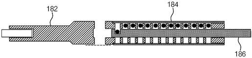
- the sample container 180 includes the sample storage part 182 and the sample cover part 184.
- the sample storage unit 182 may include a sample standby unit 182b, a sample loading unit 182a, and a sample container support unit 182c connected in series.
- the sample container 180 may store a sample and provide a sample between the upper electrode 112 and the lower electrode 122.
- the electrostatically boosted sample may be heated and melted through a heating laser.
- the sample standby part 182b may have a rod shape.
- the sample loading unit 182a may be continuously connected in the extending direction of the sample standby unit 182b and may have a rod shape.
- the sample cover part 194 may have a shape surrounding the sample waiting part 182b.
- the sample storage unit 182 may include a loading bar insertion hole 183e formed in the longitudinal direction at the center thereof.
- the loading bar insertion hole 183e may be formed in the longitudinal direction of the sample standby part 182b and may be continuously penetrated through a portion of the sample loading part 182a.
- the diameter of the loading bar insertion hole 183e may be substantially the same as the inner diameter of the sample cover part.
- the sample standby part 182b may include sample storage vertical through holes 183d penetrating in a direction perpendicular to the length direction with a first interval constant in the length direction.
- the sample waiting portion 182b may have a cylindrical shape having an outer diameter of the first diameter.
- the diameter of the sample storage vertical through holes 183d may be larger than the diameter of the sample 12.
- a thread may be formed on an outer circumferential surface of one end of the sample standby part 182b.
- the sample loading unit 182a may have a cylindrical shape having an outer diameter of a second diameter larger than the first diameter.
- the sample loading unit 182a may include one sample transfer vertical through hole 183a.
- the sample transfer vertical through hole 183a may be formed on a surface where the sample storage vertical through hole 183d is visible and vertically penetrate the sample loading unit 182a and may be connected to the loading bar insertion hole 183e.
- One surface of the sample loading vertical through hole 183a of the sample loading unit 182a may include a flat portion 183c treated as a plane.
- the sample container 180 may rotate in such a manner that the flat part 183c faces downward or upward.
- Slits 183b may be formed on both side surfaces of the sample loading unit 182a perpendicular to the direction in which the sample transfer vertical through hole 183a is formed.
- the slit 183b may be connected to the sample transfer vertical through hole 183a.
- the slit 183b may be used to check whether the sample is mounted by naked eye or using a laser beam.
- the sample container support part 182c may include a support groove 183f formed at one end thereof in the extending direction at one end thereof.
- the connecting portion 187 may be inserted into the support groove 183f and fixed to the vacuum chamber.
- the sample cover part 184 may have a shape surrounding the sample waiting part 182b.
- the sample cover 184 may have a cylindrical shape.
- the inner diameter of the sample cover part 184 may be the same as the outer diameter of the sample standby part 182b.
- a screw groove may be formed on an inner circumferential surface of one end of the sample cover 184. The screw groove may be fixed by being coupled to the thread of the sample standby portion 182b.
- the outer diameter of the sample cover portion 194 may be substantially the same as the outer diameter of the sample loading portion 182a.
- the sample loading bar 185 may have a cylindrical shape and include sample grooves 185a formed at the first interval in the longitudinal direction, and may be inserted into the loading bar insertion hole 183e.
- the sample 12 may be mounted in the sample grooves 185a.
- the sample transfer bar 186 has a cylindrical shape and includes one transfer groove 186a on an outer circumferential surface thereof, and may be inserted into the loading bar insertion hole 183e, and perform linear motion and rotational motion. Can be.
- the sample 12 may be mounted in the transfer groove 186a and transferred.
- the sample transfer bar 186 may position the sample 12 mounted in the transfer groove 186a in the sample transfer vertical through hole 183a.
- the loading tip accommodating part 192 may accommodate a standard loading tip disposed under the sample transfer vertical through hole 183a.
- the standard loading tip 194a may have a recessed end for transporting the sample.
- the sample 12 may be mounted to the standard loading tip 194a through the sample transfer vertical through hole 183a.
- the standard loading tip 194a may be vertically raised by the vertical transfer unit 174 to place the sample between the upper electrode 112 and the lower electrode 122 for electrostatic levitation.
- the loading tip accommodating part 192 may include a plurality of loading tip accommodating through holes 192a arranged in a line, and at least one experimental tip 194b having different structures mounted on the loading tip accommodating through holes 192a. 194d).
- the loading tip receiving part 192 may have a rectangular parallelepiped shape.
- the loading tip receiving through holes 192a may be formed to be aligned in the longitudinal direction of the loading tip receiving part 192.
- the loading tip receiving through hole 192a may include an upper through hole having a first diameter and a lower through hole having a second diameter smaller than the first diameter.
- the upper through hole and the lower through hole may be continuously arranged vertically aligned with each other.
- the plate lower plate 172 includes a trench 172a extending in a direction perpendicular to a direction in which the sample container 180 extends on an upper surface thereof.
- a plate lower plate through hole 172b is disposed at the center of the trench 172a.
- the loading tip receiver 192 may move along the trench 172a of the dish lower plate 172.
- the horizontal moving part mounted in the vacuum chamber 14 may be connected to a side surface of the loading tip receiver 192.
- various experimental tips may be selected.
- the recovery plate 162 may be fixed to the lower plate plate 172 through a recovery plate support rod.
- the lower plate 172 may be fixed to the vacuum chamber 14.
- the vertical transfer unit 174 may vertically transfer the standard loading tip 194a or the experimental tip through the plate bottom plate through hole 172b formed at the center of the plate bottom plate 172.
- the experimental tips 194b to 194d include a needle tip 194c in the form of a pointed needle for inducing metastable crystal phases that may be generated from a supercooled liquid molten liquid sample, and a nozzle for discharging gas to the center for air support of the sample. And at least one of a gas-lift loading tip 194b having a recessed and recessed end, or a quenching tip 194d having a flat end.
- the standard loading tip 194a may include a first cylindrical portion having a first diameter and a second cylindrical portion having a second diameter greater than the first diameter.
- the end of the first portion may be recessed to mount the sample 12.
- a groove is formed at the end of the second portion, and the end of the vertical transfer portion is inserted into the groove, so that the vertical transfer portion can vertically transfer the standard loading tip and the sample.
- the molten sample can be in a state of supercooling (where the liquid is kept in the liquid state in the solid temperature region).
- This supercooled state is a metastable liquid state where materials with new structures and properties can be found.
- the crucible for containing the molten liquid can cause contamination and impurity inflow.
- the crucible itself may cause heterogeneous nucleation.
- this metastable supercooled liquid can be utilized to develop materials with new structures and properties.
- the needle tip 194c may have a predetermined crystal structure.
- the needle tip 194c may have a body-centered cubic (BCC) lattice, a face-centered cubic (FCC) lattice, and a hexagonal closed-packed (HCP) structure.
- BCC body-centered cubic
- FCC face-centered cubic
- HCP hexagonal closed-packed
- the needle tip 194c having a predetermined crystal structure is in contact with the supercooled molten liquid sample, and the supercooled molten liquid sample may be crystallized to have a crystal structure guided by the needle tip 194c.
- a needle tip 194c of the BCC structure can be used.
- a needle tip 194c of FCC structure can be used to direct the sample to a crystal having an FCC structure.
- the needle tip 194c may include a first portion of a cylindrical shape having a first diameter and a second portion of a cone shape.
- the second portion of the cone shape may have a predetermined crystal structure.
- the needle tip 194c may be charged with the same amount of charge as the charged state of the sample. In addition, the needle tip 194c may move downward while rotating to induce a predetermined crystal growth.
- the vertical transfer unit 174 may additionally provide a rotational movement of the needle tip 194c.
- the needle tip 194c can generate a metastable crystalline phase, monocrystalline growth, and monocrystalline seed in a subcooled liquid state. By contacting the needle tip with the subcooling liquid according to the degree of subcooling, the crystallization rate can be controlled and the microstructure of the crystal can be controlled.
- the quench tip 194d may have a cylindrical shape having a constant diameter.
- One end of the quenching tip 194d may be a flat surface, and a groove for coupling the vertical transfer unit 174 may be formed at the other end of the quenching tip 194d.
- the quench tip 194d may be used to quench the electrostatically boosted sample. Specifically, the quenching tip may be vertically raised by the vertical transfer unit 174 to the same height as the quenching plate 148. Subsequently, by removing the voltage between the upper electrode 112 and the lower electrode 122 of the electrostatic flotation device, the sample may fall on the quenching tip 194d.
- a calorimeter disposed around the quench plate 148 may measure the quenching process of the sample 12 by the quenching tip 194d. Before the sample falls on the quench tip 194d, the sample may be cooled to a solid state. The quenching tip may quench the sample to provide a metastable crystalline phase. The formed solid state sample may be quenched by the quenching tip.
- Gas-lift flotation tip 194b has a structure similar to standard loading tip 194a. However, gas-lift loading tip 194b includes a nozzle at the center thereof. Accordingly, gas is provided through the nozzle, and the gas may gas support the sample. The gas may be provided through a pipe-shaped vertical conveying portion 174.
- the size of the cartridge loading the sample can be reduced. Accordingly, the size of the vacuum chamber is reduced, and the vacuum state of the vacuum chamber can be secured in a short time. Accordingly, the time required for the experiment can be reduced.
- the sample can be recovered to the original cartridge.
- loss of the sample can be prevented.
- a sample may be recovered to its original position at all times due to receipt of the collection.
- 3A to 3Q are diagrams illustrating a method of operating a sample loading apparatus according to an embodiment of the present invention.
- the sample loading bar 185 has a cylindrical shape and includes sample grooves 185a formed at the first interval in the longitudinal direction, and a sample is disposed in the sample grooves 185a of the sample loading bar 185.
- the fields 12 are each mounted.
- the sample loading bar 185 is inserted into the loading bar insertion hole 183e of the sample container.
- the flat part 183c of the sample container may be disposed to face downward.
- the sample container 180 and the sample loading bar 185 rotate 180 degrees together. Accordingly, the sample 12 may be accommodated in all of the lower surface of the sample container 180. In this case, the flat part 183c of the sample container may be disposed to face upward.
- the sample loading bar 185 is removed.
- the sample transfer bar 186 is inserted into the loading bar insertion hole 183e.
- the sample transfer bar 186 has a cylindrical shape and may include one transfer groove 186a on an outer circumferential surface thereof.
- the transfer groove 186a may coincide with the position of the first sample.
- the transfer groove 186a may be inserted to face the sample, and the sample transfer bar may be inserted such that the transfer groove 186a faces downward.
- the flat part 183c of the sample container may be disposed to face upward.
- the sample transfer bar 186 may be connected to the rotary and linear motion portion.
- the sample container 180 and the sample transfer bar 186 may rotate 180 degrees.
- the planar portion 183c of the sample container may be disposed to face downward, and the transfer groove 186a may be disposed to face upward.
- the first sample may be mounted in the transfer groove 186a.
- connection part 187 may be inserted into the support groove of the sample container 180 and fixed to the vacuum chamber 14.
- the vacuum chamber is then evacuated to maintain a vacuum.
- a first sample may be disposed on the sample transfer vertical through hole 183a by the sample transfer bar 186.
- the loading tip receiver 192 may move and the standard loading tip 194a may be aligned with the bottom of the first sample.
- the sample transfer bar 186 may be rotated 180 degrees to drop the sample, and the first sample may be mounted on the standard loading tip 194a.
- the sample transfer bar 185 may backward.
- the standard loading tip 194a may be disposed between the upper electrode and the lower electrode by the vertical movement of the vertical transfer unit 174. Accordingly, the first sample 12 on the standard loading tip 194a may be electrostatically buoyed by a high voltage applied between the upper electrode and the lower electrode. The standard loading tip 194a may be lowered and accommodated in the loading tip receiving unit 192.
- the first sample may be melted by a heating laser. After the predetermined experiment, the first sample can be cooled by radiation. The first sample may undergo a crystallization step in a suspended state. To this end, a needle tip having a predetermined crystal structure is selected by the movement of the loading tip receiver 192. The selected needle tip may contact the lower surface of the electrostatically boosted sample by the vertical transfer.
- the standard loading tip 194a may be vertically raised by the vertical moving part 174 to be disposed below the first sample. Subsequently, the high voltage applied between the upper electrode and the lower electrode is removed, and the first sample may be mounted to the standard loading tip 194a.
- the standard loading tip 194a is lowered so that the first sample may be disposed below the sample transfer vertical through hole.
- the transfer groove 186a of the sample transfer bar is disposed to face the bottom surface, and the transfer groove 186a of the sample transfer bar is disposed on the sample transfer vertical through hole 183a. Can be.
- the vertical transfer unit 174 raises the standard loading tip 194a and may place a first sample disposed on the standard loading tip 194a in the transfer groove 186a. .
- the first sample may be mounted in the transfer groove 186a.
- the standard loading tip 194a may be disposed in the loading tip receiver 192.
- the first sample may be disposed on the empty sample storage vertical through hole 183d.
- the first sample may be stored in the lower portion of the empty sample storage vertical through hole 183d.
- the sample transfer bar 186 rotates 180 degrees and moves backward, so that a second sample may be mounted in the transfer groove 186a.
- the operation described above may be repeated until the experiment on all samples is complete.
- Ultra high purity single crystals and single crystal seeds can be used for a variety of experiments.
- the single crystal can be used as a seed for growing a crystal.
- the electrostatic flotation device of the present invention can be used.
- the electrostatically boosted molten liquid sample may be present in a meta-stable state of subcooling.
- the liquid sample When a needle tip having a predetermined crystal structure comes into contact with the liquid sample, the liquid sample is a normal stable liquid when the meta-stable state of the liquid sample matches the crystal structure of the needle tip. It can crystallize into the crystal structure of the needle tip, which cannot be obtained in the liquid state. In addition, in the stable liquid state, by contacting the needle tip with the stable liquid, high purity single crystal can be formed. In addition, despite the same liquid sample, when the metastable state has a plurality of crystal structures, the liquid sample may be crystallized according to the crystal structure of the needle tip.
- the supercooled liquid sample may have different microstructures according to the crystallization rate.
- a dendrite is a crystal in which a metal is regularly deposited around a small nucleus when a molten metal solidifies to form a dendritic skeleton. If the cooling rate is fast, many branches occur at the same time and small grains grow.
- the rate at which crystallization occurs may vary depending on the degree of subcooling of the liquid. Accordingly, the microstructure of the crystal may vary. Therefore, it is possible to study the material properties according to the crystallization rate of the sample.
- FIGS. 1 to 3 are views for explaining an electrostatic levitation device according to another embodiment of the present invention. Descriptions overlapping with those described in FIGS. 1 to 3 will be omitted.
- the electrostatic flotation device may be used as a single crystal growth device.
- the sample may be positioned between the upper electrode 112 and the lower electrode 122 using a standard loading tip 194a having a recessed end for transporting the sample 12.
- the standard loading tip 194a may be lowered and received in the loading tip accommodating part 192.
- the loading tip receiver 192 may move along the trench 172a so that the needle tip may be aligned with the plate lower plate through hole 172b.
- an electric field applied between the upper electrode and the lower electrode may electrostatically support the sample.
- the heating laser 23 may heat and melt the electrostatic boosted sample.
- the molten liquid sample may exist in a supercooled state by radiation in an electrostatically boosted state.
- the needle tip 194c may then be raised to contact the supercooled molten liquid sample 12.
- the needle tip in the form of a pointed needle may induce any desired crystal structure that may arise from the metastable supercooled molten liquid sample 12. Accordingly, the liquid sample can be crystallized through a phase transition. Additionally, the needle tip 194c may perform a rotational motion.
- the sample when the sample is silicon, the sample may be phase transition into a single crystal by contact of the needle tip.
- the needle tip may have a silicon crystal structure.
- the liquid sample can be crystallized in the solid state.
- the crystallized sample can be used as a single crystal seed used in other crystal growth methods. If the metastable state of the liquid sample in the supercooled state may have a plurality of crystal structures, a predetermined crystal structure may be selected among the plurality of crystal structures according to the crystal structure of the needle tip.
- the needle tip 194c may be in contact with the supercooled molten liquid sample to adjust the crystallization rate. Accordingly, the microcrystalline structure of the cooled solid sample may be changed.
- the needle tip 194c may be lowered again after contact with the liquid sample 12 and may be accommodated in the loading tip accommodating part 192.
- the loading tip receiver 192 may move along the trench, so that the standard loading tip 194a may be aligned with the plate lower plate through hole 172b.
- the standard loading tip 194a may be raised to collect the suspended samples.
- the needle tip 94c may induce a metastable crystalline phase in the liquid state, induce single crystal growth, and generate a single crystal seed. And, depending on the degree of subcooling, upon contact of the subcooled liquid sample with the needle tip. The rate of crystallization of the supercooled liquid sample can be controlled. Accordingly, microstructures of various crystallized samples can be generated.
- FIG. 5 is a view for explaining an electrostatic support device according to another embodiment of the present invention. Descriptions overlapping with those described in FIGS. 1 to 3 will be omitted.
- the electrostatic levitation device 100 may include a quenching plate 148.
- the quenching plate 148 may be disposed between the electrode support part 142 and the recovery dish 162.
- a radiation thermometer 149 may be mounted to the vacuum chamber to check the crystallization rate, cooling rate, and temperature.
- the sample can be positioned between the upper electrode and the lower electrode using a standard loading tip 194a having a recessed end for transferring the sample.
- the standard loading tip 194c may be lowered and received in the loading tip receiving unit 192. Subsequently, the loading tip accommodating part 192 may move along the trench 192a so that the cooling tip 194d may be aligned with the plate lower plate through hole 172b.
- an electric field applied between the upper electrode and the lower electrode may electrostatically support the sample.
- the heating laser 23 may heat and melt the electrostatic boosted sample 12.
- the molten liquid sample may be present in a supercooled state by radiation in an electrostatically boosted state.
- the cooling tip 194d may rise to the upper surface of the quench plate 142.
- the supercooled molten liquid sample may fall on the cooling tip 194d and be rapidly cooled.
- the radiation thermometer 149 may measure the crystallization rate, cooling rate, and temperature of the sample 12.
- the subcooled liquid sample and the cooling team may be quenched.
- a metastable crystal phase can be obtained.
- FIG. 6 is a view for explaining a flotation device according to another embodiment of the present invention. Descriptions overlapping with those described in FIGS. 1 to 3 will be omitted.
- the sample may be positioned between the upper electrode and the lower electrode using a gas-lift loading tip 194b for transferring the sample.
- the gas-lift loading tip 194b includes a nozzle at the center and may provide gas through the nozzle. Accordingly, the sample 12 may be suspended in the air.
- the heating laser 23 may heat and melt the electrostatic boosted sample.
- the molten liquid sample may be present in a supercooled state by radiation in a gas-lifted state.
- the sample is electrostatically buoyed using standard loading tip 194a and gas-lift loading tip 194d can be used to provide a predetermined gas to the sample 12.
- the surface of the sample may be coded with a new material.
- the upper electrode and the lower electrode used for the electrostatic flotation can be removed.
- the auxiliary electrode is a conductor sample, it may be used for the rotational movement.
Landscapes
- Engineering & Computer Science (AREA)
- Health & Medical Sciences (AREA)
- Clinical Laboratory Science (AREA)
- Mechanical Engineering (AREA)
- General Engineering & Computer Science (AREA)
- Life Sciences & Earth Sciences (AREA)
- Physics & Mathematics (AREA)
- Chemical & Material Sciences (AREA)
- Analytical Chemistry (AREA)
- Biochemistry (AREA)
- General Health & Medical Sciences (AREA)
- General Physics & Mathematics (AREA)
- Immunology (AREA)
- Pathology (AREA)
- Sampling And Sample Adjustment (AREA)
Abstract
본 발명은 시료 로딩 장치 및 정전기 부양 장치를 제공한다. 이 정전기 부양 장치는 봉 형상의 시료 대기부, 시료 대기부의 연장 방향으로 연속적으로 연결되고 봉 형상의 시료 로딩부를 포함하는 시료 보관부, 및 시료 대기부를 감싸는 시료 덮개부를 포함한다. 시료 보관부는 중심에 길이 방향으로 형성된 로딩 바(loading bar) 삽입 홀을 포함하고, 로딩 바 삽입 홀은 시료 대기부를 관통하여 형성되고 시료 로딩부의 일부에 연속적으로 관통하여 형성되고, 시료 대기부는 길이 방향으로 일정한 제1 간격을 가지고 길이 방향에 수직한 방향으로 관통하는 시료 보관 수직 관통홀들을 포함하고, 시료 로딩부는 하나의 시료 이송 수직 관통홀을 포함하고, 시료 이송 수직 관통홀은 시료 보관 수직 관통홀이 보이는 면에 형성되고 시료 로딩부를 수직으로 관통하고 로딩 바 삽입 홀과 연결된다.
Description
본 발명은 시료 로딩 장치에 관한 것으로, 더 구체적으로, 정전기 부양 장치에 사용되는 시료 로딩 장치에 관한 것이다.
본 발명은 정전기 부양 장치에 관한 것으로, 더 구체적으로, 로딩 팁 수납부를 가지는 정전기 부양 장치에 관한 것이다.
정전기 부양 장치는 정전기장을 이용하여 하전된 시료를 부양하는 장치이다. 상기 정전기 부양 장치는 부양된 시료를 용융시켜 물질 특성 연구에 사용될 수 있다.
본 발명의 일 실시예에 따른 시료 로딩 장치는 연속적으로 시료를 공급할 수 있는 시료 로딩 장치를 제공하는 것이다.
본 발명의 일 실시예에 따른 정전기 부양 장치는 다양한 실험을 수행할 수 있는 팁을 가지는 정전기 부양 장치를 제공하는 것이다.
본 발명의 일 실시예에 따른 시료 로딩 장치는 제1 지름의 외경을 가지는 원통 형상의 시료 대기부 및 상기 제1 지름보다 큰 제2 지름의 외경을 가지는 원통 형상의 시료 로딩부를 포함하는 시료 보관부; 및 상기 제2 지름의 외경을 가지고 상기 시료 대기부를 감싸는 원통 형상의 시료 덮개부를 포함한다. 상기 시료 보관부는 중심에 길이 방향으로 형성된 로딩 바(loading bar) 삽입 홀을 포함한다. 상기 로딩 바 삽입 홀은 상기 시료 대기부를 관통하여 형성되고 상기 시료 로딩부의 일부에 연속적으로 관통하여 형성된다. 상기 시료 대기부는 길이 방향으로 일정한 제1 간격을 가지고 상기 길이 방향에 수직한 방향으로 관통하는 시료 보관 수직 관통홀들을 포함하고, 상기 시료 로딩부는 하나의 시료 이송 수직 관통홀을 포함하고, 상기 시료 이송 수직 관통홀은 상기 시료 보관 수직 관통홀이 보이는 면에 형성되고 상기 시료 로딩부를 수직으로 관통하고 상기 로딩 바 삽입 홀과 연결된다.
본 발명의 일 실시예에 있어서, 상기 시료 이송 수직 관통홀이 노출된 일면은 평면으로 형성될 수 있다.
본 발명의 일 실시예에 있어서, 상기 시료 이송 수직 관통홀이 형성된 방향에 수직하게 상기 시료 로딩부의 양 측면에 형성된 슬릿을 더 포함하고, 상기 슬릿은 상기 시료 이송 수직 관통홀과 연결될 수 있다.
본 발명의 일 실시예에 있어서, 원기둥 형상을 가지고 길이 방향으로 상기 제1 간격으로 형성된 시료 홈들을 포함하고, 상기 로딩 바(loading bar) 삽입 홀에 삽입되는 시료 로딩 바를 더 포함하고, 상기 시료는 상기 시료 홈들에 장착될 수 있다.
본 발명의 일 실시예에 있어서, 원기둥 형상을 가지고 외주면에 하나의 이송 홈을 포함하고, 상기 로딩 바(loading bar) 삽입 홀에 삽입되는 시료 이송 바를 더 포함하고, 상기 시료는 상기 이송 홈에 장착되어 이송될 수 있다.
본 발명의 일 실시예에 있어서, 상기 시료 이송 바는 상기 이송 홈에 장착된 시료를 상기 이송 수직 관통홀에 위치시키고, 상기 이송 수직 관통홀의 하부에 배치되고 상기 시료를 이송하기 위한 끝이 함몰된 홈을 가지는 표준 로딩 팁(loading tip)을 수납하는 로딩 팁 수납부를 더 포함할 수 있다. 상기 시료는 상기 이송 수직 관통홀을 통하여 상기 표준 로딩 팁에 장착되고, 상기 표준 로딩 팁은 수직으로 상승하여 상기 시료를 정전기 부양을 위한 상부 전극과 하부 전극 사이에 배치할 수 있다.
본 발명의 일 실시예에 있어서, 상기 로딩 팁 수납부는 일렬로 정렬된 복수의 팁 수납 관통홀들; 및 상기 팁 수납 관통홀에 장착되는 상기 표준 로딩 팁과 다른 구조의 실험용 팁을 포함할 수 있다.
본 발명의 일 실시예에 있어서, 상기 실험용 팁은 과냉각된 액체 용융 액체 시료로부터 발생 가능한 준안정 결정상을 유도하기 위한 뾰족한 바늘 형태의 바늘 팁, 상기 시료를 공기 부양하기 위하여 중심에 기체를 토출하는 노즐을 포함하고 끝이 함몰된 홈을 가지는 기체 부양 로딩 팁, 및 끝이 평면인 급랭용 팁 중에서 적어도 하나를 포함할 수 있다.
본 발명의 일 실시예에 있어서, 상부 전극; 상기 상부 전극에 수직으로 이격되어 배치되고 그 중심에 하부 전극 관통홀을 포함하는 하부 전극; 상기 상부 전극의 중심과 상기 하부 전극의 중심을 연결하는 축에 수직한 평면에 서로 대칭적으로 배치되는 제1 내지 제4 보조 전극들; 상기 하부 전극의 상기 하부 전극 관통홀에 연결되고 유전체 물질로 형성된 원통 형상을 포함하는 하부 전극 지지부; 상기 하부 전극 지지부가 장착되고 상기 보조 전극들을 지지하는 보조 전극 지지봉이 장착되고 중심에 전극 지지판 관통홀을 포함하는 전극 지지판; 상기 전극 지지판의 하부에 배치되고 그 중심에 회수 접시 관통홀을 포함하는 콘 형상의 회수 접시; 상기 회수 접시와 상기 전극 지지판을 연결하는 전극 지지판 지지봉; 상기 회수 접시와 상기 전극 지지판 사이에 배치되고 중심에 담금질판 관통홀을 포함하는 담금질판; 상기 담금질판과 상기 회수 접지를 연결하는 담금질판 지지봉; 상기 회수 접지의 하부면에 장착되고, 수평 방향의 시료통 관통홀을 포함하는 시료통 지지대; 상부면 상에서 상기 시료 덮개부가 연장되는 방향에 수직한 방향으로 연장되는 트렌치를 포함하고 상기 시료 덮개부의 하부에 배치되는 접시 하부판; 및 상기 트렌치에 삽입되고 중심에 관통홀을 포함하고 상기 접시 하부판과 상기 시료통 사이에 배치되는 상기 로딩 팁 수납부 중에서 적어도 하나를 더 포함할 수 있다.
본 발명의 일 실시예에 있어서, 상기 시료 보관부는 상기 시료 대기부에 연속적으로 연결되는 시료통 지지부를 더 포함하고, 상기 시료통 지지부는 일단에 연장 방향으로 그 중심에 형성된 지지 홈을 포함하고, 상기 지지 홈을 통하여 진공 용기에 고정될 수 있다.
본 발명의 일 실시예에 따른 시료 로딩 장치는 제1 지름의 외경을 가지는 원통 형상의 시료 대기부 및 상기 제1 지름보다 큰 제2 지름의 외격을 가지는 원통 형상의 시료 로딩부를 포함하는 시료 보관부; 및 상기 제2 지름의 외경을 가지고 상기 시료 대기부를 감싸는 원통 형상의 덮개부를 포함하고 상기 시료 보관통은 중심에 길이 방향으로 형성된 로딩 바(loading bar) 삽입 홀을 포함한다. 상기 로딩 바 삽입 홀은 상기 시료 대기부를 관통하여 형성되고 상기 시료 로딩부의 일부에 연속적으로 관통하여 형성되고, 상기 시료 대기부는 길이 방향으로 일정한 제1 간격을 가지고 상기 길이 방향에 수직한 방향으로 관통하는 시료 보관 수직 관통홀들을 포함하고, 상기 시료 로딩부는 상기 시료 보관 수직 관통홀이 보이는 면에 형성되고 상기 시료 로딩부를 수직으로 관통하고 상기 로딩 바 삽입 홀과 연결되는 하나의 시료 이송 수직 관통홀을 포함하고, 시료 로딩 바는 원기둥 형상을 가지고 길이 방향으로 상기 제1 간격으로 형성된 시료 홈들을 포함하고 상기 로딩 바(loading bar) 삽입 홀에 삽입되고, 시료 이송 바는 원기둥 형상을 가지고 외주면에 하나의 이송 홈을 포함하고 상기 로딩 바(loading bar) 삽입 홀에 삽입된다. 상기 시료 로딩 장치의 동작 방법은 상기 시료 로딩 바를 이용하여 시료를 상기 시료 보관 수직 관통홀들에 수납하는 단계; 상기 시료 로딩 바를 제거하고 상기 시료 이송 바를 상기 로딩 바(loading bar) 삽입 홀에 삽입하는 단계; 및 상기 시료 이송 바를 이용하여 상기 시료 보관 수직 관통홀들에 수납된 시료들 중에서 하나를 상기 시료 이송 수직 관통홀에 위치시키는 단계를 포함한다.
본 발명의 일 실시예에 따른 시료 로딩 장치는 봉 형상의 시료 대기부; 상기 시료 대기부의 연장 방향으로 연속적으로 연결되고 봉 형상의 시료 로딩부를 포함하는 시료 보관부; 및 상기 시료 대기부를 감싸는 시료 덮개부를 포함한다. 상기 시료 보관부는 중심에 길이 방향으로 형성된 로딩 바(loading bar) 삽입 홀을 포함하고, 상기 로딩 바 삽입 홀은 상기 시료 대기부를 관통하여 형성되고 상기 시료 로딩부의 일부에 연속적으로 관통하여 형성되고, 상기 시료 대기부는 길이 방향으로 일정한 제1 간격을 가지고 상기 길이 방향에 수직한 방향으로 관통하는 시료 보관 수직 관통홀들을 포함하고, 상기 시료 로딩부는 하나의 시료 이송 수직 관통홀을 포함하고, 상기 시료 이송 수직 관통홀은 상기 시료 보관 수직 관통홀이 보이는 면에 형성되고 상기 시료 로딩부를 수직으로 관통하고 상기 로딩 바 삽입 홀과 연결된다.
본 발명의 일 실시예에 따른 시료 로딩 장치의 동작 방법은 하나의 시료 이송 수직 관통홀 및 상기 시료 이송 수직 관통홀과 이격되고 일정한 간격으로 형성된 시료 보관 수직 관통홀들을 포함하고, 연장되는 방향으로 그 중심에 형성된 로딩 바(loading bar) 삽입 홀을 포함하고, 외주면은 덮개로 싸여있는 시료통에 시료 로딩 바를 이용하여 시료들을 상기 시료 보관 수직 관통홀들에 수납하는 단계; 상기 시료 로딩 바를 제거하고 상기 시료 이송 바를 상기 로딩 바(loading bar) 삽입 홀에 삽입하는 단계; 및 상기 시료 이송 바를 이용하여 상기 시료 보관 수직 관통홀들에 수납된 시료들 중에서 하나를 상기 시료 이송 수직 관통홀에 위치시키는 단계를 포함한다.
본 발명의 일 실시예에 따른 정전기 부양 장치는 하나의 시료 이송 수직 관통홀 및 상기 시료 이송 수직 관통홀과 이격되고 일정한 간격으로 형성된 시료 보관 수직 관통홀들을 포함하고, 연장되는 방향으로 그 중심에 형성된 로딩 바(loading bar) 삽입 홀을 포함하고, 외주면은 덮개로 싸여있는 시료통; 및 시료를 이송하기 위한 표준 로딩 팁(loading tip)을 수납하는 로딩 팁 수납부를 포함한다. 상기 표준 로딩 팁은 상기 이송 수직 관통홀에 배치된 시료를 수직으로 상승시켜 상기 시료를 정전기 부양을 위한 상부 전극과 하부 전극 사이에 배치한다.
본 발명의 일 실시예에 따른 정전기 부양 장치는 상부 전극; 그 중심에 하부 전극 관통홀을 포함하고 상기 상부 전극에 수직으로 이격되어 배치된 하부 전극; 및 상기 상부 전극과 상기 하부 전극 사이에 시료를 이송하기 위한 표준 로딩 팁과 실험용 팁을 수납하고 일렬로 정렬된 복수의 로딩 팁 수납 관통홀들을 가지는 로딩 팁 수납부를 포함한다. 상기 로딩 팁 수납부는 로딩 팁 수납 관통홀들이 정렬된 방향으로 선형 운동을 수행한다.
본 발명의 일 실시예에 있어서, 상기 실험용 팁은 준안정 상태의 과냉각된 용융 액체 시료로부터 발생 가능한 소정의 결정 구조를 유도하기 위한 뾰족한 바늘 형태의 바늘 팁일 수 있다.
본 발명의 일 실시예에 있어서, 상기 실험용 팁은 과냉각된 용융 액체 시료로부터 단결정 또는 단결정 시드(seed)를 만들 수 있다.
본 발명의 일 실시예에 있어서, 상기 실험용 팀은 끝이 평면인 급랭용 팁일 수 있다.
본 발명의 일 실시예에 있어서, 하나의 시료 이송 수직 관통홀 및 상기 시료 이송 수직 관통홀과 이격되고 일정한 간격으로 형성된 시료 보관 수직 관통홀들을 포함하고, 연장되는 방향으로 그 중심에 형성된 로딩 바(loading bar) 삽입 홀을 포함하고, 외주면은 덮개로 싸여있는 시료통을 더 포함할 수 있다.
본 발명의 일 실시예에 있어서, 상기 로딩 팁 수납부가 장착되는 접시 하부판을 더 포함하고, 상기 접시 하부판은 일면에 형성된 트렌치를 포함하고, 상기 로딩 팁 수납부는 상기 트렌치에 삽입되어 직선 운동을 수행할 수 있다.
본 발명의 일 실시예에 있어서, 상기 상부 전극의 중심과 상기 하부 전극의 중심을 연결하는 축에 수직한 평면에 서로 대칭적으로 배치되는 제1 내지 제4 보조 전극들; 상기 하부 전극의 상기 하부 전극 관통홀에 연결되고 원통 형상을 가지는 하부 전극 지지부; 상기 하부 전극 지지부가 장착되고 상기 보조 전극들을 지지하는 보조 전극 지지봉이 장착되고 중심에 전극 지지판 관통홀을 포함하는 전극 지지판; 상기 전극 지지판의 하부에 배치되고 중심에 회수 접시 관통홀을 포함하는 콘 형상의 회수 접시; 상기 회수 접시의 하부면에 장착되고, 수평 방향의 시료통 관통홀을 포함하는 시료통 지지대; 상기 시료통 관통홀에 삽입되는 시료통; 및 상부면에서 상기 시료통이 연장되는 방향에 수직한 방향으로 연장되는 트렌치를 포함하고 상기 시료통의 하부에 배치되는 접시 하부판; 중에서 적어도 하나를 더 포함할 수 있다.
본 발명의 일 실시예에 따른 정전기 부양 장치의 동작 방법은 시료를 이송하기 위한 끝이 함몰된 홈을 가지는 표준 로딩 팁을 이용하여 시료를 상부 전극과 하부 전극 사이에 위치시키는 단계; 상기 상부 전극과 상기 하부 전극 사이에 전기장을 인가하여 상기 시료를 정전기 부양시키는 단계; 정전기 부양된 시료에 가열 레이저를 이용하여 가열하고 용융시키는 단계; 상기 가열 레이저를 제거하여 상기 시료를 복사 냉각시키는 단계; 및 과냉각된 용융 액체 시료로부터 소정의 결정 구조를 유도하기 위한 뾰족한 바늘 형태의 바늘 팁을 상기 과냉각된 용융 액체 시료에 접촉시키는 단계를 포함할 수 있다.
본 발명의 일 실시예에 따른 정전기 부양 장치의 동작 방법은 시료를 이송하기 위한 끝이 함몰된 홈을 가지는 표준 로딩 팁을 이용하여 시료를 상부 전극과 하부 전극 사이에 위치시키는 단계; 상기 상부 전극과 상기 하부 전극 사이에 전기장을 인가하여 상기 시료를 정전기 부양하는 단계; 정전기 부양된 시료를 가열 레이저를 이용하여 가열하여 용융시키는 단계; 및 과냉각된 용융 액체 시료로부터 결정화 속도를 조절하기 위한 뾰족한 바늘 형태의 바늘 팁을 부양된 과냉각된 용융 액체 시료에 접촉시키는 단계를 포함할 수 있다.
본 발명의 일 실시예에 따른 정전기 부양 장치의 동작 방법은 시료를 이송하기 위한 끝이 함몰된 홈을 가지는 표준 로딩 팁을 이용하여 시료를 상부 전극과 하부 전극 사이에 위치시키는 단계; 상기 상부 전극과 상기 하부 전극 사이에 전기장을 인가하여 상기 시료를 정전기 부양하는 단계; 정전기 부양된 시료를 가열 레이저를 이용하여 가열하여 용융시키는 단계; 끝이 평면인 급랭용 로딩 팁을 상기 시료의 하부에 배치시키는 단계; 및 상기 상부 전극과 상기 하부 전극 사이에 인가된 전기장을 제거하여 상기 시료를 상기 급랭용 팁 상에 떨어트리는 단계를 포함한다.
본 발명의 일 실시예에 따른 단결정 제조 방법은 정전기 부양 장치에서 시료를 상부 전극과 하부 전극 사이에 위치시키는 단계; 상기 상부 전극과 상기 하부 전극 사이에 전기장을 인가하여 상기 시료를 정전기 부양하는 단계; 정전기 부양된 시료를 가열 레이저를 이용하여 가열하여 용융시키는 단계; 상기 가열 레이저를 제거하여 상기 시료를 복사 냉각시키는 단계; 과냉각된 용융 액체 시료로부터 소정의 결정 구조를 유도하기 위한 뾰족한 바늘 형태의 바늘 팁을 상기 과냉각된 용융 액체 시료에 접촉시키는 단계; 및 상기 과냉각된 용융 액체 시료가 상전이(phase transition)하여 결정화되는 단계를 포함할 수 있다.
본 발명의 일 실시예에 따른 부양 장치는 회수 접시 관통홀을 포함하는 콘 형상의 회수 접시; 상기 회수 접시의 하부면에 장착되고, 수평 방향의 시료통 관통홀을 포함하는 시료통 지지대; 상기 시료통 관통홀에 삽입되는 시료통; 상부면에서 상기 시료통이 연장되는 방향에 수직한 방향으로 연장되는 트렌치를 포함하고 상기 시료통의 하부에 배치되는 접시 하부판; 및 상기 회수 접시 상부에 시료를 이송하기 위한 노즐을 포함하는 기체 부양 로딩 팁을 수납하고 상기 트렌치에 삽입되는 로딩 팁 수납부를 포함한다.
본 발명의 일 실시예에 따른 부양 장치는 회수 접시 관통홀을 포함하는 콘 형상의 회수 접시; 상기 회수 접시의 하부면에 장착되고, 수평 방향의 시료통 관통홀을 포함하는 시료통 지지대; 상기 시료통 관통홀에 삽입되는 시료통; 상부면에서 상기 시료통이 연장되는 방향에 수직한 방향으로 연장되는 트렌치를 포함하고 상기 시료통의 하부에 배치되는 접시 하부판; 및 상기 회수 접시 상부에 시료를 이송하기 위한 노즐을 포함하는 기체 부양 로딩 팁을 수납하고 상기 트렌치에 삽입되는 로딩 팁 수납부를 포함한다. 이 부양 장치의 동작 방법은 상기 기체 부양 로딩 팁을 사용하여 시료를 부양시키는 단계; 기체 부양된 시료를 가열 레이저를 이용하여 가열하여 용융시키는 단계; 및 상기 가열 레이저를 제거하여 상기 시료를 복사 냉각시키는 단계를 포함한다.
본 발명의 일 실시예에 따른 시료 로딩 장치는 표준 로딩 팁으로 연속적으로 시료를 로딩할 수 있으며, 실험용 팁은 정전기 부양된 상태의 시료에 접촉하여 다양한 실험을 제공할 수 있다.
바늘 팁은 과냉각 액체상태에서의 준안정 결정상을 유도하고 단결정 성장 및 단결정 시드를 생성할 수 있다. 상기 바늘 팁은 과냉각 정도에 따른 액체 시료와 상기 바늘 팁의 접촉에 따라 결정화 속도를 조절하여 미세구조를 조절할 수 있다.
급랭용 팁은 과냉각 액체를 평탄한 팁에 떨어뜨려 급랭하여 준안정적 결정상을 제공할 수 있다. 급랭용 팀은 형성된 고체상을 평탄한 팁에 떨어뜨려 급랭할 수 있다. 가스 부양 로딩 팁은 시료를 기체로 부양할 수 있다.
본 발명의 일 실시예에 따르면, 실험 목적에 따라 다양한 실험을 수행할 수 있는 다양한 팁이 제공될 수 있다.
본 발명의 일 실시예에 따르면, 시료를 로딩하는 카트리지의 크기가 감소됨에 따라 진공 챔버의 크기가 감소된다. 이에 따라, 진공을 보다 짧은 시간에 확보할 수 있어, 실험에 필요한 시간을 줄일 수 있다. 또한, 실험 후 원래 시료가 있던 카트리지로 회수 가능하다. 따라서, 깔대기 구조의 회수 접시를 이용하여 시료의 손실이 방지될 수 있다.
본 발명의 일 실시예에 따른 정전기 부양 장치에서, 실험용 팁은 정전기 부양된 상태의 시료에 접촉하여 다양한 실험을 제공할 수 있다. 이에 따라, 과냉각 액체 시료로부터 새로운 물성이 유도될 수 있다. 또한, 초고순도의 단결정 및 단결정 시드(seed)가 성장될 수 있다.
바늘 팁은 과냉각 액체상태에서의 준안정 결정상을 유도하고 단결정 성장 및 단결정 시드를 생성할 수 있다. 상기 바늘 팁은 과냉각 정도에 따른 액체 시료와 상기 바늘 팁의 접촉에 따라 결정화 속도를 조절하여 미세구조를 조절할 수 있다.
급랭용 팁은 과냉각 액체를 평탄한 팁에 떨어뜨려 급랭하여 준안정적 결정상을 제공할 수 있다. 급내용 팀은 형성된 고체상을 평탄한 팁에 떨어뜨려 급랭할 수 있다. 가스 부양 로딩 팁은 시료를 기체로 부양할 수 있다.
본 발명의 일 실시예에 따르면, 실험 목적에 따라 단일 환경에서 다양한 실험을 수행할 수 있는 다양한 팁이 제공될 수 있다.
본 발명의 일 실시예에 따르면, 시료를 로딩하는 카트리지의 크기가 감소됨에 따라 진공 챔버의 크기가 감소된다. 이에 따라, 진공을 보다 짧은 시간에 확보할 수 있어, 실험에 필요한 시간을 줄일 수 있다. 또한, 실험 후 원래 시료가 있던 카트리지로 회수 가능하다. 따라서, 깔대기 구조의 회수 접시를 이용하여 시료의 손실이 방지될 수 있다.
도 1a은 본 발명의 일 실시예에 따른 정전기 부양 장치를 설명하는 사시도이다.
도 1b는 도 1a의 정전기 부양 장치의 평면도이다.
도 1c는 도 1b의 I-I'선을 따라 자른 단면도이다.
도 1d는 도 1b의 II-II'선을 따라 자른 단면도이다.
도 2a는 본 발명의 일 실시예에 따른 시료통과 로딩 팁 수납부를 설명하는 사시도이다.
도 2b는 도 2a의 시료통의 단면도이다.
도 3a 내지 도 3q는 본 발명의 일 실시예에 따른 시료 로딩 장치의 동작 방법을 설명하는 도면들이다.
이하, 첨부된 도면을 참조로 본 발명의 바람직한 실시예들에 대하여 보다 상세히 설명한다. 이하의 도면들에서 동일한 참조부호는 동일한 구성요소를 지칭하며, 도면상에서 각 구성요소의 크기는 설명의 명료성과 편의상 과장되어 있을 수 있다.
고진공 하에서 대전된 시료는 두 개의 전극 사이에 정전계(electrostiatic electric field intensity)에 의하여 공중 부양될 수 있다.
부양된 시료를 정해진 위치에 안정적으로 부양하기 위해서, 시료의 위치변화에 따라 X, Y, Z 방향으로 전기장 또는 전압이 제어된다.
복수의 시료들에서 다양한 실험을 수행하기 위하여, 복수의 시료를 장착할 수 있는 시료통과 상기 시료통에서 이송된 시료에 다양한 실험을 수행할 수 있는 다양한 팁이 요구된다.
본 발명의 일 실시예에 따른 시료 로딩 장치는 정전기 부양 장치에 복수의 시료를 순차적으로 정전기 부양시키고, 각 시료에 다양한 실험을 수행할 수 있는 팁을 구비할 수 있다.
도 1a은 본 발명의 일 실시예에 따른 정전기 부양 장치를 설명하는 사시도이다.
도 1b는 도 1a의 정전기 부양 장치의 평면도이다.
도 1c는 도 1b의 I-I'선을 따라 자른 단면도이다.
도 1d는 도 1b의 II-II'선을 따라 자른 단면도이다.
도 2a는 본 발명의 일 실시예에 따른 시료통과 로딩 팁 수납부를 설명하는 사시도이다.
도 2b는 도 2a의 시료통의 단면도이다.
도 1 및 도 2를 참조하면, 상기 정전기 부양 장치(100)는 상부 전극(112), 상기 상부 전극(112)에 수직으로 이격되어 배치된 하부 전극(122), 상기 상부 전극(112)의 중심과 상기 하부 전극(122)의 중심을 연결하는 z 축에 수직한 xy 평면에 서로 대칭적으로 배치되는 제1 내지 제4 보조 전극들(132a~132d)을 포함한다. 시료(12)는 상기 상부 전극(112)과 상기 하부 전극(122) 사이에 부양된다.
상기 정전기 부양 장치(100)는 원통형의 진공 챔버(14)의 내부에 배치될 수 있다. 상기 진공 챔버(14)는 밀리토르(mTorr) 이하의 극진공으로 배기될 수 있다. 상기 진공 챔버(14)는 복수의 창문을 포함할 수 있다. 상기 진공 챔버(14)의 창문의 외부에는 상기 시료를 가열하기 위하여 가열 레이저(23)가 배치될 수 있다. 상기 가열 레이저(23)는 120도 간격으로 배치된 이산화탄소 레이저(CO2 laser)일 수 있다.
상기 시료(12)는 양의 전하로 대전될 수 있다. 상기 시료(12)가 상기 가열 레이저에 의하여 가열됨에 따라, 상기 시료(12)는 전하를 손실할 수 있다. 이에 따라, 상기 손실된 전하를 공급하기 위하여, UV 광원(24)은 상기 시료(12)에 조사될 수 있다. UV 광은 광전 효과에 의하여 전자를 방출시켜, 상기 시료(12)를 양의 전하로 대전시킬 수 있다. UV 광원의 반대 측에는 카메라(25)가 상기 진공 챔버(14)에 장착될 수 있다.
상기 시료(12)는 상기 상부 전극(112)과 상기 하부 전극(122) 사이에 부양되고, 상기 시료(12)의 x축 위치는 x축 위치 감지부(position sensitive detector;PSD)에 의하여 측정될 수 있다. 상기 x축 위치 감지부(287)는 일차원 또는 2차원에서 광의 위치를 측정하는 장치일 수 있다. 상기 x축 위치 감지부(287)와 x축 프로브 광원(22)은 상기 시료(12)를 중심으로 대각선 상에 서로 마주보도록 배치될 수 있다. 상기 x축 프로브 광원(22)은 He-Ne 레이저일 수 있다.
또한, y축 위치 및 z축 위치를 측정하기 위하여, Y-Z 위치 감지부(283)와 제2 프로 광원(21)은 상기 시료(12)를 중심으로 대각선 상에 서로 마주보도록 배치될 수 있다. 상기 제2 프로브 광원(21)은 He-Ne 레이저일 수 있다. 상기 제1 프로브 광원(22)과 상기 제2 프로브 광원(21)은 상기 시료(12)를 중심으로 90도 간격으로 배치될 수 있다. 위치 감지부는 프로브 광원의 그림자 영상을 통하여 상기 시료의 위치를 측정할 수 있다.
상기 x축 위치 감지부(287)의 측정 결과는 제1 되먹임 제어부(286)에 제공될 수 있다. 또한, 상기 Y-Z 위치 감지부(283)의 측정 결과는 제2 되먹임 제어부(282)에 제공될 수 있다. 상기 제1 되먹임 제어부(286)는 PID(비례적분미분) 제어를 통하여 상기 시료의 x 축 위치를 제어하기 제1 제어 신호를 x축 고전압 발생기(288)에 제공할 수 있다. 또한, 상기 제2 되먹임 제어부(282)는 PID 제어를 통하여 상기 시료의 y 축 위치를 제어하기 위한 제2 제어 신호를 y축 고전압 발생기(284)에 제공할 수 있다. 또한, 상기 제2 되먹임 제어부(282)는 PID 제어를 통하여 상기 시료(12)의 z 축 위치를 제어하기 위한 제3 제어 신호를 z축 고전압 발생기(285)에 제공할 수 있다.
상기 시료(12)가 도전체인 경우, 유도 기전력에 의한 회전 운동을 상기 시료(12)에 제공하기 위하여, 유도 코일부(154a~154d)가 상기 보조 전극들(132a~132d) 사이에 배치될 수 있다. 상기 유도 코일부(154a~154d)는 상기 시료(12)를 중심으로 서로 마주 보도록 배치될 수 있다.
서로 마주보는 제1 유도 코일부(154a) 및 제3 유도 코일부(154c)은 전기적으로 서로 직렬 연결될 수 있다. 서로 마주 보는 제2 유도 코일부(154b) 및 제4 유도 코일부(154d)은 전기적으로 서로 직렬 연결될 수 있다. 교류 전원(289)은 상기 제1 내지 제4 유도 코일에 교류 전류를 인가하여, 상기 시료(12)에 유도 기전력을 제공할 수 있다. 이에 따라, 도전성 시료는 회전할 수 있다.
상기 보조 전극(132a~132d)은 수평 운동 및 수직 운동을 수행할 수 있다. 제1 내지 제4 보조 전극(132a~132d)은 시계 방향으로 배열될 수 있다. 상기 보조 전극(132a~132d)의 수평 운동은 수평 엑튜에이터(136)에 의하여 제공될 수 있다. 상기 보조 전극(132a~132d)의 수직 운동은 수직 엑튜에이터(138)에 의하여 제공될 수 있다. x축 수평 엑튜에이터 구동부(292)는 x 축 수평 엑튜에이터(136)를 제어할 수 있으며, y축 수평 엑튜에이터 구동부(291)는 y축 수평 엑튜에이터(136)를 제어할 수 있다. x축 수평 엑튜에이터(136)는 상기 제1 보조 전극(132a) 및 제 3 보조 전극(132c)의 x축 방향의 위치를 조절할 수 있다. y축 수평 엑튜에이터(136)는 상기 제2 보조 전극(132b) 및 제4 보조 전극(132d)의 y축 위치를 조절할 수 있다.
제어부(281)는 상기 제1 되먹임 제어부(285), 제2 되먹임 제어부(282), x축 수평 엑튜에이터 구동부(292), y축 수평 엑튜에이터 구동부(291), 및 교류 전원(289)을 제어할 수 있다. 이에 따라, 상기 시료(12)는 소정의 위치에서 떨어지지 않고 안정적으로 정전기 부양될 수 있다.
상부 전극(112)은 디스크 형태의 평판 형태이고, 상기 상부 전극(112)의 모서리는 곡면처리될 수 있다. 상기 상부 전극(112)은 z 축 고전압 발생기(285)에 연결될 수 있다. 상기 상부 전극(112)은 구리 재질일 수 있다. 상기 상부 전극(112)은 상부 전극 지지부(114)에 의하여 지지될 수 있다.
상기 상부 전극 지지부(114)는 유전체일 수 있다. 상기 상부 전극(112)의 중심에는 상부 전극 관통홀(112a)이 중심에 형성될 수 있다. 상기 상부 전극 관통홀은 상기 상부 전극(112)과 상기 하부 전극(122)의 정렬을 위하여 사용될 수 있다. 상기 상부 전극 지지부(114)를 통하여 z축 고전압 발생기(285)의 고전압이 상기 상부 전극(112)에 인가될 수 있다. 이에 따라, 전기장은 중력 방향의 반대 방향으로 형성될 수 있다.
상기 하부 전극(122)은 상기 상부 전극(112)과 정렬되고 상기 상부 전극(112)과 z축을 따라 수직으로 이격되어 배치될 수 있다. 상기 하부 전극(122)은 중심에 하부 전극 관통홀(122a)을 포함할 수 있다. 상기 하부 전극 관통홀(122a)을 통하여 시료(12)가 공급될 수 있다. 상기 하부 전극(122)은 구리 재질일 수 있다. 상기 하부 전극(122)은 디스크 형태이고, 상기 하부 전극(122)의 모서리는 곡면 처리될 수 있다. 상기 하부 전극(122)은 z축 방향으로 연장되는 원통 형상의 연장부(122b)를 포함할 수 있다. 상기 연장부(122b)의 내부 표면에는 나사 홈이 형성될 수 있다.
하부 전극 지지부(124)는 유전체 재질로 형성되고, 그 중심에 하부 전극 지지부 관통홀을 포함할 수 있다. 상기 하부 전극 지지부(124)는 상기 하부 전극(122)의 상기 하부 전극 관통홀(122a)에 연결되고 원통 형상일 수 있다. 상기 하부 전극 지지부(124)의 일단의 외측 표면에는 나사 산이 형성될 수 있다. 상기 하부 전극 지지부(124)의 타단의 주위에는 와셔 형태의 와셔부(124a)를 포함할 수 있다. 이에 따라, 상기 하부 전극 지지부(124)의 일단의 나사산은 상기 연장부(122b)의 나사 홈에 결합할 수 있다. 상기 하부 전극 지지부(124)의 와셔부(124a)는 상기 전극 지지판(142)의 하부면에 고정 결합할 수 있다. 상기 하부 전극 지지부(124)는 세라믹 재질 또는 알루미나로 형성될 수 있다.
전극 지지판(142)은 상기 하부 전극 지지부(124)를 장착하고, 상기 보조 전극들(132a~132d)을 지지하는 보조 전극 지지봉(134)을 장착할 수 있다. 상기 전극 지지판(142)은 그 중심에 전극 지지판 관통홀(142a)을 포함할 수 있다. 상기 하부 전극 지지부(124)의 일단은 상기 전극 지지판 관통홀(142a)을 통과하여 상기 하부 전극(122)에 결합할 수 있다. 상기 전극 지지판(142)의 상부면은 일정한 경사를 가진 절두된 콘(truncated cone) 형태일 수 있다. 상기 전극 지지판(142)의 하부면은 평면일 수 있다. 상기 전극 지지판(142)의 상부 중심부위는 평면일 수 있다. 상기 상부 중심 부위의 지름은 상기 하부 전극의 지름과 실질적으로 동일할 수 있다. 또한, 상기 전극 지지판(142)은 십자 형태의 돌출부(146)를 포함할 수 있다. 상기 돌출부(146)의 상부면는 수평 평면을 이룰 수 있다.
상기 전극 지지판(142) 상에는 4 개의 보조 전극 지지부(134)가 상기 시료를 중심으로 대칭적으로 x축 방향 및 y축 방향으로 장착될 수 있다. 상기 보조 전극 지지부(134)는 상기 전극 지지판(142)을 관통하여 배치될 수 있다. 상기 보조 전극 지지부(134)는 상기 전극 지지판(142)의 하부면에 고정될 수 있다. 상기 전극 지지판(142)의 하부면에는 수직 엑츄에이터(138)가 장착될 수 있다. 상기 수직 엑튜에이터(138)는 상기 보조 전극 지지부(134)에 수직 운동을 제공할 수 있다.
수평 지지부(135)는 보조 전극 지지부(134)의 상단 부위를 관통하여 보조 전극(132a)에 연결될 수 있다. 상기 수평 지지부(135)는 상기 수평 엑튜에이터(138)에 연결될 수 있다. 상기 수평 엑튜에이터(138)는 상기 보조 전극(132a)에 수평 운동을 제공할 수 있다. 상기 수평 엑튜에이터(138)는 압전 소자 또는 압전 모터일 수 있다. 제1 보조 전극(132a) 및 제3 보조 전극(132c)은 상기 시료(12)를 중심으로 x 축을 따라서 서로 대향하여 배치될 수 있다. 제2 보조 전극(132b) 및 제4 보조 전극(132d)은 상기 시료(12)를 중심으로 y축을 따라 서로 대향하여 배치될 수 있다.
상기 보조 전극(132a~132d)은 4 분할된 원 원통( 4 split cicrular cylinderical shell) 형상일 수 있다. 상기 보조 전극(132a~132d)의 내측면과 외측면은 각각 일정한 곡률을 가질 수 있다. 상기 곡률은 상기 하부 전극(122)의 중심을 기준으로 한 상기 보조 전극의 배치된 위치의 반경과 동일할 수 있다. 상기 보조 전극(132a~132d)은 구리로 형성될 수 있다. 한 쌍의 보조 전극은 전기력선을 상기 시료에 집중시킬 수 있다. 이에 따라, 시료의 안정적인 위치 제거가 구현될 수 있다. 또한, 상기 보조 전극의 수직 위치는 상기 시료의 수직 위치에 따라 조절될 수 있다. 구체적으로, 상기 시료가 용융되는 과정에서 전하를 포함한 가스가 분출함에 따라, 순간적으로 상기 시료의 수직 위치가 변경될 수 있다. 이 경우, 상기 보조 전극은 상기 시료의 수직 위치에따라 이동할 수 있다. 따라서, 상기 시료의 안정적인 수직 위치 제어가 가능하다.
또한, 상기 가열 레이저의 빔과 상기 하부 전극의 중심은 오정렬될 수 있다. 이 경우, 한 쌍의 보조 전극은 일정한 간격을 유지하면서, x축 또는 y축 방향으로 이동할 수 있다. 상기 시료는 상부 전극의 중심에서 부양되지 않고 다양한 수평 위치에서 부양될 수 있다. 따라서, 가열 레이저의 정렬에 따른 시간이 감소될 수 있다.
한편, x축 고전압 발생기 및 y축 고전압 발생기의 출력은 미세조절이 어렵다. 따라서, 한 쌍의 보조 전극 사이의 전기장의 세기는 미세조절되기 어렵다. 이를 극복하기 위하여, 한 쌍의 보조 전극 사이의 간격이 조절될 수 있다. 이에 따라, 한 쌍의 보조 전극 사이의 전기장의 세기는 미세 조절될 수 있다. 따라서, 상기 시료의 안정적인 수평 위치 제어가 가능하다.
상기 전극 지지판(142)의 십자 형태의 돌출부(146)에는 유도 코일부(154a~154d)가 배치될 수 있다. 상기 유도 코일부(154a~154d)는 유도 코일(157d), 유도 코일이 감기는 코일 보빈(155d), 및 상기 코일 보빈을 감싸는 코일 보빈 덮개(156d)를 포함할 수 있다. 유도 코일부(154a~154d)는 제1 내지 제4 유도 코일부를 포함할 수 있다.
제1 유도 코일부(154a)는 상기 제1 보조 전극(132a)과 제2 보조 전극(132b) 사이에 배치되고, 제2 유도 코일부(154b)는 상기 제2 보조 전극(132b)과 제3 보조 전극(152c) 사이에 배치되고, 제3 유도 코일부(154c)는 상기 제3 보조 전극(132c)과 상기 제4 보조 전극(132d) 사이에 배치되고, 제4 유도 코일부(154d)는 상기 제4 보조 전극(132d)과 제1 보조 전극(132a) 사이에 배치될 수 있다. 코일 보빈(155d)은 상기 하부 전극(122)을 향하도록 기울어질 수 있다. 상기 유도 코일부(154a~154d)는 도전성 시료에 회전력을 제공할 수 있다.
회수 접시(162)는 상기 전극 지지판(142)의 하부에 배치되고 중심에 회수 접시 관통홀(162a)을 포함하고, 콘 형상을 포함할 수 있다. 상기 회수 접시(162)와 상기 전극 지지판(142)은 전극 지지판 지지봉(165)에 의하여 고정될 수 있다. 상기 회수 접시(162)의 상부면은 콘 형상을 가질 수 있다. 상기 회수 접시(162)의 중심 하부면은 평면이고, 상기 회수 접시(162)의 외곽 하부면은 콘 형상일 수 있다. 상기 회수 접시(162)의 외곽은 일정한 두께를 가질 접시 형태일 수 있다. 상기 회수 접시(162)는 떨어진 시료를 다시 회수할 수 있다. 떨어진 시료는 상기 회수 접시 관통홀(152a)을 통하여 시료통(180)으로 회수될 수 있다.
시료통 지지대(166)는 상기 회수 접지의 하부면에 장착되고, 수평 방향의 시료통 관통홀(166a)을 포함할 수 있다.
담금질판(148)은 상기 회수 접시(162)와 상기 전극 지지판(142) 사이에 배치되고 중심에 담금질판 관통홀(148a)을 포함할 수 있다. 상기 담금질판(148)의 상부면은 곡면 처리될 수 있다. 구체적으로, 상기 담금질판(148)의 상부면은 절두된 콘 형상일 수 있다. 담금질판 지지봉(164)은 상기 담금질판(148)과 상기 회수 접시(162)를 연결하고 고정할 수 있다.
시료통(180)은 상기 시료통 관통홀(166a)에 삽입될 수 있다. 시료통(180)은 상기 시료 보관부(182) 및 시료 덮개부(184)를 포함한다. 상기 시료 보관부(182)는 연속적으로 연결된 시료 대기부(182b), 시료 로딩부(182a), 및 시료통 지지부(182c)를 포함할 수 있다. 상기 시료통(180)은 시료를 보관하고 상기 상부 전극(112)과 상기 하부 전극(122) 사이에 시료를 제공할 수 있다. 정전기 부양된 시료는 가열 레이저를 통하여 가열되어 용융될 수 있다.
상기 시료 대기부(182b)는 봉 형상일 수 있다. 상기 시료 로딩부(182a)는 상기 시료 대기부(182b)의 연장 방향으로 연속적으로 연결되고 봉 형상일 수 있다. 시료 덮개부(194)는 상기 시료 대기부(182b)를 감싸는 형상을 가질 수 있다.
상기 시료 보관부(182)는 중심에 길이 방향으로 형성된 로딩 바(loading bar) 삽입 홀(183e)을 포함할 수 있다. 상기 로딩 바 삽입 홀(183e)은 상기 시료 대기부(182b)의 길이 방향으로 형성되고, 상기 시료 로딩부(182a)의 일부에 연속적으로 관통하여 형성될 수 있다. 상기 로딩 바 삽입 홀(183e)의 직경은 상기 시료 덮개부의 내경과 실질적으로 동일할 수 있다.
상기 시료 대기부(182b)는 길이 방향으로 일정한 제1 간격을 가지고 상기 길이 방향에 수직한 방향으로 관통하는 시료 보관 수직 관통홀들(183d)을 포함할 수 있다. 시료 대기부(182b)는 제1 지름의 외경을 가지는 원통 형상일 수 있다. 시료 보관 수직 관통홀들(183d)의 직경은 시료(12)의 직경보다 클 수 있다. 시료 대기부(182b)의 일단의 외주면에는 나사산이 형성될 수 있다.
시료 로딩부(182a)는 상기 제1 지름보다 큰 제2 지름의 외격을 가지는 원통 형상일 수 있다. 상기 시료 로딩부(182a)는 하나의 시료 이송 수직 관통홀(183a)을 포함할 수 있다. 상기 시료 이송 수직 관통홀(183a)은 상기 시료 보관 수직 관통홀(183d)이 보이는 면에 형성되고 상기 시료 로딩부(182a)를 수직으로 관통하고 상기 로딩 바 삽입 홀(183e)과 연결될 수 있다. 시료 로딩부(182a)의 상기 시료 이송 수직 관통홀(183a)이 노출된 일면은 평면으로 처리된 평면부(183c)를 포함할 수 있다. 상기 평면부(183c)는 아래 방향 또는 위 방향으로 향하도록, 상기 시료통(180)은 회전 운동할 수 있다.
상기 시료 이송 수직 관통홀(183a)이 형성된 방향에 수직하게 상기 시료 로딩부(182a)의 양 측면에 슬릿(183b)이 형성될 수 있다. 상기 슬릿(183b)은 상기 시료 이송 수직 관통홀(183a)과 연결될 수 있다. 상기 슬릿(183b)은 시료가 장착되었는지 여부를 육안 또는 레이저 빔을 사용하여 확인하기 위하여 사용될 수 있다.
상기 시료통 지지부(182c)는 일단에 연장 방향으로 그 중심에 형성된 지지 홈(183f)을 포함할 수 있다. 연결부(187)는 상기 지지 홈(183f)에 삽입되고 진공 챔버에 고정될 수 있다.
시료 덮개부(184)는 상기 시료 대기부(182b)를 감싸는 형상을 가질 수 있다. 상기 시료 덮개부(184)는 원통 형상일 수 있다. 상기 시료 덮개부(184)의 내경은 상기 시료 대기부(182b)의 외경과 동일할 수 있다. 상기 시료 덮개부(184)의 일단의 내주면에는 나사 홈이 형성될 수 있다. 상기 나사 홈은 상기 시료 대기부(182b)의 나사산과 결합하여 고정될 수 있다. 시료 덮개부(194)의 외경은 상기 시료 로딩부(182a)의 외경과 실질적으로 동일할 수 있다.
시료 로딩 바(185)는 원기둥 형상을 가지고 길이 방향으로 상기 제1 간격으로 형성된 시료 홈들(185a)을 포함하고, 상기 로딩 바(loading bar) 삽입 홀(183e)에 삽입될 수 있다. 상기 시료(12)는 상기 시료 홈들(185a)에 장착될 수 있다.
시료 이송 바(186)는 원기둥 형상을 가지고 외주면에 하나의 이송 홈(186a)을 포함하고, 상기 로딩 바(loading bar) 삽입 홀(183e)에 삽입될 수 있고, 직선 운동 및 회전 운동을 수행할 수 있다. 상기 시료(12)는 상기 이송 홈(186a)에 장착되어 이송될 수 있다. 상기 시료 이송 바(186)는 상기 이송 홈(186a)에 장착된 시료(12)를 상기 시료 이송 수직 관통홀(183a)에 위치시킬 수 있다.
로딩 팁 수납부(192)는 상기 시료 이송 수직 관통홀(183a)의 하부에 배치된 표준 로딩 팁(standard loading tip)을 수납할 수 있다. 상기 표준 로딩 팁(194a)은 상기 시료를 이송하기 위한 끝이 함몰된 홈을 가질 수 있다. 상기 시료(12)는 상기 시료 이송 수직 관통홀(183a)을 통하여 상기 표준 로딩 팁(194a)에 장착될 수 있다. 상기 표준 로딩 팁(194a)은 수직 이송부(174)에 의하여 수직으로 상승하여 상기 시료를 정전기 부양을 위한 상부 전극(112)과 하부 전극(122) 사이에 배치할 수 있다.
상기 로딩 팁 수납부(192)는 일렬로 정렬된 복수의 로딩 팁 수납 관통홀들(192a), 및 상기 로딩 팁 수납 관통홀(192a)에 장착되는 적어도 하나의 서로 다른 구조의 실험용 팁(194b~194d)을 포함할 수 있다. 상기 로딩 팁 수납부(192)는 직육면체 형태를 가질 수 있다. 상기 로딩 팁 수납 관통홀들(192a)은 상기 로딩 팁 수납부(192)의 길이 방향으로 정렬되어 형성될 수 있다. 상기 로딩 팁 수납 관통홀(192a)은 제1 직경을 가진 상부 관통홀과 제1 직경보다 작은 제2 직경을 가진 하부 관통홀을 포함할 수 있다. 상기 상부 관통홀과 상기 하부 관통홀은 수직으로 서로 정렬되어 연속적으로 배치될 수 있다.
접시 하부판(172)은 상부면에 상기 시료통(180)이 연장되는 방향에 수직한 방향으로 연장되는 트렌치(172a)를 포함한다. 상기 트렌치(172a)의 중심에는 접시 하부판 관통홀(172b)이 배치된다. 상기 로딩 팁 수납부(192)는 상기 접시 하부판(172)의 상기 트렌치(172a)를 따라 이동할 수 있다. 상기 로딩 팁 수납부(192)를 이동시키기 위하여, 진공 챔버(14)에 장착된 수평 이동부는 상기 로딩 팁 수납부(192)의 측면에 결할 수 있다. 상기 로딩 팁 수납부(192)가 상기 트렌치를 따라 이동함에 따라, 다양한 실험용 팁이 선택될 수 있다. 회수 접시(162)는 회수 접시 지지봉을 통하여 상기 하부 접시판(172)에 고정될 수 있다. 상기 하부 접시판(172)은 진공 챔버(14)에 고정될 수 있다.
수직 이송부(174)는 상기 접시 하부판(172)의 중심에 형성된 접시 하부판 관통홀(172b)을 통하여 상기 표준 로딩 팁(194a) 또는 실험용 팁을 수직으로 이송시킬 수 있다.
상기 실험용 팁(194b~194d)은 과냉각된 액체 용융 액체 시료로부터 발생 가능한 준안정 결정상을 유도하기 위한 뾰족한 바늘 형태의 바늘 팁(194c), 상기 시료를 공기 부양하기 위하여 중심에 기체를 토출하는 노즐을 포함하고 끝이 함몰된 홈을 가지는 기체 부양 로딩 팁(194b), 또는 끝이 평면인 급랭용 팁(194d) 중에서 적어도 하나를 포함할 수 있다.
표준 로딩 팁(194a)은 제1 직경을 가진 원기둥 형상의 제1 부위와 제1 직경보다 큰 제2 직경을 가진 원기둥 형상의 제2 부위를 포함할 수 있다. 제1 부위의 끝은 함몰되어 시료(12)가 장착될 수 있다. 상기 제2 부위의 끝에 홈이 형성되고, 상기 홈에 수직 이송부의 끝이 삽입되어, 상기 수직 이송부는 상기 표준 로딩 팁 및 시료를 수직으로 이송할 수 있다.
정전기 부양된 시료는 가열 레이저를 이용하여 용융된 후, 상기 가열레이저를 제거함으로써, 용융된 시료는 과냉각 (액체가 고체의 온도 영역에서 액체 상태로 유지하는 것) 상태가 될 수 있다. 이 과냉각 상태는 준안정 액체 상태로써, 새로운 구조 및 특성을 가지는 물질이 발견될 수 있다.
기존의 접촉식 용기를 쓰는 결정 성장 장치에서는, 용융 액체를 담기 위한 도가니가 오염과 불순물 유입을 유발할 수 있다. 또한, 도가니 자체가 이종핵생성(heterogeneous nucleation)을 일으킬 수 있다. 따라서, 고순도의 단결성 성장 또는 과냉각을 통한 새로운 특성의 물질의 발견이 어렵다. 따라서 접촉을 제거한 부양상태에서, 이 준안정 상태의 과냉각 액체는 새로운 구조 및 특성을 가진 물질 개발을 위해서 활용될 수 있다.
정전기 부양된 용융된 액체 시료로부터 새로운 결정상을 발견하거나 단결정을 성장하기 위한 기법이 제안된다.
과냉각된 용융 액체 시료로부터 발생 가능한 준안정 결정을 유도하기 위해서, 서로 다른 결정 종류의 탐침을 설치한다. 상기 바늘 팁(194c)은 소정의 결정 구조를 가질 수 있다. 예를 들어, 상기 바늘 팁(194c)은 body-centered cubic(BCC) lattice, face-centered cubic(FCC) lattice, Hexagonal Closed-Packed(HCP) structure를 가질 수 있다. 소정의 결정 구조를 가진 상기 바늘 팁(194c)은 과냉각된 용융 액체 시료에 접촉되고, 상기 과냉각된 용융 액체 시료는 상기 바늘 팁(194c)이 유도하는 결정 구조를 가지도록 결정화될 수 있다. 상기 시료를 BCC 구조를 가진 결정으로 유도하기 위하여, BCC 구조의 바늘 팁(194c)이 사용될 수 있다. 또한, 상기 시료를 FCC 구조를 가진 결정으로 유도하기 위하여, FCC 구조의 바늘 팁(194c)이 사용될 수 있다.
상기 바늘 팁(194c)은 제1 직경을 가진 원기둥 형상의 제1 부위와 원뿔 형태의 제2 부위를 포함할 수 있다. 상기 원뿔 형태의 제2 부위는 소정의 결정 구조를 가질 수 있다.
상기 바늘 팁(194c)은 상기 시료의 하전 상태와 동일한 양의 전하로 대전될 수 있다. 또한, 상기 바늘 팁(194c)은 소정의 결정 성장을 유도하기 위하여 회전하면서 아래로 이동할 수 있다. 수직 이송부(174)는 상기 바늘 팁(194c)의 회전 운동을 추가적으로 제공할 수 있다. 상기 바늘 팁(194c)은 과냉각 액체 상태에서의 준안정 결정상의 유도, 단결정 성장 및 단결정 시드를 생성할 수 있다. 과냉각 정도에 따라 과냉각 액체에 상기 바늘 팁을 접촉시킴으로써, 결정화 속도가 조절될 수 있고, 결정의 미세 구조가 조절될 수 있다.
급랭용 팁(194d)은 일정한 직경을 가진 원기둥 형상일 수 있다. 상기 급랭용 팁(194d)의 일단은 평면이고, 상기 급랭용 팁(194d)의 타단에는 수직 이송부(174)가 결합하기 위한 홈이 형성될 수 있다. 상기 급랭용 팁(194d)은 정전기 부양된 시료를 급랭시키기 위하여 사용될 수 있다. 구체적으로, 상기 급랭용 팁은 상기 담금질판(148)과 같은 높이로 상기 수직 이송부(174)에 의하여 수직 상승할 수 있다. 이어서, 상기 정전기 부양 장치의 상부 전극(112)과 상기 하부 전극(122) 사이의 전압을 제거하여, 상기 시료가 상기 급랭용 팁(194d) 상에 떨어질 수 있다. 상기 담금질판(148)의 주위에 배치된 열량계는 상기 급랭용 팁(194d)에 의한 상기 시료(12)의 급랭 과정을 측정할 수 있다. 상기 시료가 상기 급랭용 팁(194d) 상에 떨어지기 전에, 상기 시료는 고체 상태로 냉각될 수 있다. 상기 급랭용 팁은 시료를 급랭하여 준안정 결정상을 제공할 수 있다. 형성된 고체 상태의 상기 시료는 상기 급랭용 팁에 의하여 급랭될 수 있다.
기체 부양 로당 팁(194b)은 표준 로딩 팁(194a)과 유사한 구조를 가지고 있다. 그러나, 기체 부양 로딩 팁(194b)은 그 중심에 노즐을 포함한다. 이에 따라, 상기 노즐을 통하여 기체가 제공되고, 상기 기체는 상기 시료를 기체 부양할 수 있다. 상기 기체는 파이프 형상의 수직 이송부(174)를 통하여 제공될 수 있다.
본 발명의 일 실시예에 따르면, 시료를 로딩하는 카트리지의 크기가 감소될 수 있다. 이에 따라, 진공 챔버의 크기가 감소되고, 상기 진공 챔버의 진공 상태는 빠른 시간에 확보될 수 있다. 이에 따라, 실험에 필요한 시간이 감소될 수 있다.
또한, 실험 후 시료는 원래 있던 카트리지로 회수될 수 있다. 이에 따라, 시료의 손실이 방지될 수 있다. 또한, 회수 접수로 인해 항상 원래 위치로 시료가 회수 될 수 있다.
이하, 시료 로딩 장치의 동작 방법이 설명된다.
도 3a 내지 도 3q는 본 발명의 일 실시예에 따른 시료 로딩 장치의 동작 방법을 설명하는 도면들이다.
도 3a를 참조하면, 시료 로딩 바(185)는 원기둥 형상을 가지고 길이 방향으로 상기 제1 간격으로 형성된 시료 홈들(185a)을 포함하고, 상기 시료 로딩 바(185)의 시료 홈들(185a)에 시료들(12)이 각각 장착된다.
이어서, 상기 시료 로딩 바(185)는 상기 시료통의 상기 로딩 바(loading bar) 삽입 홀(183e)에 삽입된다. 이 경우, 상기 시료통의 평면부(183c)는 아래를 향하도록 배치될 수 있다.
도 3b를 참조하면, 상기 시료통(180) 및 상기 시료 로딩 바(185)는 같이 180도 회전한다. 이에 따라, 상기 시료(12)는 상기 시료통(180)의 하부면에 모두 수납될 수 있다. 이 경우, 상기 시료통의 평면부(183c)는 위를 향하도록 배치될 수 있다.
도 3c를 참조하면, 상기 시료 로딩 바(185)는 제거된다.
도 3d를 참조하면, 시료 이송 바(186)는 상기 로딩 바(loading bar) 삽입 홀(183e)에 삽입된다. 상기 시료 이송 바(186)는 원기둥 형상을 가지고 외주면에 하나의 이송 홈(186a)을 포함할 수 있다. 상기 이송 홈(186a)은 첫 번째 시료의 위치와 일치할 수 있다. 상기 이송 홈(186a)은 시료를 바라보기 위하여, 상기 시료 이송바는 상기 이송 홈(186a)이 아래를 바라보도록 삽입될 수 있다. 이 경우, 상기 시료통의 평면부(183c)는 위를 향하도록 배치될 수 있다. 또한, 상기 시료 이송 바(186)는 회전 및 직선 운동부에 연결될 수 있다.
도 3e를 참조하면, 상기 시료통(180) 및 상기 시료 이송 바(186)는 180도 회전할 수 있다. 이 경우, 상기 시료통의 평면부(183c)는 아래를 바라보도록 배치될 수 있고, 상기 이송 홈(186a)은 위를 바라보도록 배치될 수 있다. 제1 시료는 상기 이송 홈(186a)에 장착될 수 있다.
이어서, 연결부(187)는 상기 시료통(180)의 지지 홈에 삽입되고 진공 챔버(14)에 고정될 수 있다.
이어서, 진공 챔버는 배기되어 진공 상태를 유지한다.
도 3f를 참조하면, 제1 시료는 상기 시료 이송 바(186)에 의하여 시료 이송 수직 관통홀(183a) 상에 배치될 수 있다.
도 3g를 참조하면, 로딩 팁 수납부(192)는 이동하고, 표준 로딩 팁(194a)은 상기 제1 시료의 하부에 정렬될 수 있다.
도 3h를 참조하면, 상기 시료 이송 바(186)는 180도 회전하여 상기 시료를 떨어트리고, 상기 제1 시료는 상기 표준 로딩 팁(194a) 상에 장착될 수 있다.
도 3i를 참조하면, 상기 시료 이송 바(185)는 뒤로 후진할 수 있다.
상기 표준 로딩 팁(194a)은 수직 이송부(174)의 수직 운동에 의하여 상부 전극과 하부 전극의 사이에 배치될 수 있다. 이에 따라, 상기 표준 로딩 팁(194a) 상의 제1 시료(12)는 상기 상부 전극과 상기 하부 전극의 사이에 인가된 고전압에 의하여 정전기 부양될 수 있다. 상기 표준 로딩 팁(194a)은 하강하여, 상기 로딩 팁 수납부(192)에 수납될 수 있다.
이어서, 상기 제1 시료는 가열 레이저에 의하여 용융될 수 있다. 소정의 실험이 끝나면, 상기 제1 시료는 복사에 의하여 냉각될 수 있다. 상기 제1 시료는 부양된 상태에서 결정화 단계를 거칠 수 있다. 이를 위하여, 소정의 결정 구조를 가진 바늘 팁은 상기 로딩 팁 수납부(192)의 이동에 의하여 선택된다. 선택된 바늘 팁은 상기 수직 이송부에 의하여 정전기 부양된 시료의 하부면에 접촉될 수 있다.
이어서, 상기 표준 로딩 팁(194a)은 수직 이동부(174)에 의하여 수직 상승하여, 상기 제1 시료의 하부에 배치될 수 있다. 이어서, 상기 상부 전극과 상기 하부 전극 사이에 인가된 고전압이 제거되고, 상기 제1 시료는 상기 표준 로딩 팁(194a)에 장착될 수 있다.
도 3j를 참조하면, 상기 표준 로딩 팁(194a)은 하강하여, 제1 시료는 상기 시료 이송 수직 관통홀의 하부에 배치될 수 있다.
도 3k를 참조하면, 상기 시료 이송 바의 이송 홈(186a)은 아래면을 바라보도록 배치되고, 상기 시료 이송 바의 상기 이송 홈(186a)은 상기 시료 이송 수직 관통홀(183a) 상에 배치될 수 있다.
도 3l을 참조하면, 상기 수직 이송부(174)는 상기 표준 로딩 팁(194a)을 상승시키며, 상기 표준 로딩 팁(194a) 상에 배치된 제1 시료를 상기 이송 홈(186a)에 배치시킬 수 있다.
도 3m를 참조하면, 상기 시료 이송 바(186)는 180도 회전함에 따라, 상기 제1 시료는 상기 이송 홈(186a)에 장착될 수 있다.
도 3n를 참조하면, 상기 표준 로딩 팁(194a)은 로딩 팁 수납부(192)에 배치될 수 있다.
도 3o를 참조하면, 상기 시료 이송 바(186)가 후진함에 따라, 상기 제1 시료는 비어있는 시료 보관 수직 관통홀(183d) 상에 배치될 수 있다.
도 3p를 참조하면, 상기 시료 이송 바(186)가 180도 회전함에 따라, 상기 제1 시료는 빈 시료 보관 수직 관통홀(183d)의 하부에 수납될 수 있다.
도 3q를 참조하면, 상기 시료 이송 바(186)는 180도 회전하고, 뒤로 후진하여, 상기 이송 홈(186a)에 제2 시료가 장착될 수 있다. 모든 시료에 대한 실험이 완료될 때까지, 위에서 설명한 동작이 반복될 수 있다.
초고순도의 단결정 및 단결정 시드(seed)는 다양한 실험을 위하여 사용될 수 있다. 상기 단결정은 결정을 성장시키기 위한 시드(seed)로 사용될 수 있다. 따라서, 상기 단결정을 형성하기 위하여, 본 발명의 정전기 부양 장치가 사용될 수 있다. 정전기 부양된 용융된 액체 시료는 과냉각 상태의 준안정(meta-stable) 상태로 존재할 수 있다.
소정의 결정 구조를 가지는 바늘 팁이 상기 액체 시료에 접촉하면, 상기 액체 시료의 준안정(meta-stable) 상태가 상기 바늘 팁의 결정 구조와 일치하는 경우, 상기 액체 시료는 보통의 안정적 액체(stable liquid) 상태에서는 얻을 수 없는, 상기 바늘 팁의 결정 구조로 결정화될 수 있다. 또한 안정적 액체 상태에서는 상기 바늘 팁을 상기 안정적 액체에 접촉하므로써, 고순도의 단결정이 형성될 수 있다. 또한, 동일한 액체 시료임에도 불구하고, 상기 준안정 상태가 복수의 결정 구조를 가질 경우, 상기 바늘 팁의 결정 구조에 따라 상기 액체 시료는 결정화될 수 있다.
또한, 과냉각 상태의 액체 시료는 결정화 속도에 따라 서로 다른 미세구조(micro-structure)를 가질 수 있다. 덴드라이트(dendrite)는 용융금속이 응고할 때 작은 핵을 중심으로 하여 금속이 규칙적으로 퇴적되어 수지상의 골격을 형성한 결정이다. 냉각속도가 빠르면 동시에 발생하는 가지가 많고 성장하는 결정립은 작다.
상기 바늘 팁이 상기 액체 시료에 접촉하는 경우, 상기 액체의 과냉각의 정도에 따라, 결정화가 일어나는 속도가 변경될 수 있다. 이에 따라, 결정의 미세구조가 달라질 수 있다. 따라서, 상기 시료의 결정화 속도에 따른 물질 특성을 연구할 수 있다.
도 4는 본 발명의 다른 실시예에 따른 정전기 부양 장치를 설명하는 도면이다. 도 1 내지 도 3에서 설명한 것과 중복되는 설명은 생략된다.
도 4를 참조하면, 정전기 부양 장치는 단결정 성장 장치로 사용될 수 있다. 시료(12)를 이송하기 위한 끝이 함몰된 홈을 가지는 표준 로딩 팁(194a)을 이용하여 시료는 상부 전극(112)과 하부 전극(122) 사이에 위치될 수 있다. 상기 표준 로딩 팁(194a)은 하강하여 로딩 팁 수납부(192)에 수납될 수 있다. 이어서, 상기 로딩 팁 수납부(192)는 트렌치(172a)를 따라 이동하여, 바늘 팁이 상기 접시 하부판 관통홀(172b)과 정렬될 수 있다.
이어서, 상기 상부 전극과 상기 하부 전극 사이에 인가된 전기장은 상기 시료를 정전기 부양할 수 있다.
이어서, 상기 가열 레이저(23)는 상기 정전기 부양된 시료를 가열하여 용융시킬 수 있다.
이어서, 상기 시료가 용융된 후, 상기 가열 레이저(23)가 제거되면, 상기 용융된 액체 시료는 정전기 부양된 상태에 복사에 의하여 과냉각 상태로 존재할 수 있다.
이어서, 바늘 팁(194c)이 상승하여 상기 과냉각된 용융 액체 시료(12)와 접촉할 수 있다. 뾰족한 바늘 형태의 바늘 팁은 준안정 상태의 과냉각된 용융 액체 시료(12)로부터 발생 가능한 소정의 결정 구조를 유도할 수 있다. 이에 따라, 상기 액체 시료는 상전이(phase transition)을 통하여 결정화될 수 있다. 추가적으로 상기 바늘 팁(194c)은 회전 운동을 수행할 수 있다.
예를 들어, 상기 시료가 실리콘인 경우, 상기 시료는 상기 바늘 팁의 접촉에 의하여 단결정으로 상전이(phase transition) 할 수 있다. 상기 바늘 팁은 실리콘 결정 구조를 가질 수 있다. 이에 따라, 액체 시료는 고체 상태로 결정화될 수 있다. 상기 결정화된 시료는 다른 결정 성장 방법에 사용되는 단결정 시드(seed)로 사용될 수 있다. 만약, 과냉각 상태의 액체 시료의 준안정 상태가 복수의 결정 구조를 가질 수 있다면, 상기 바늘 팁의 결정 구조에 따라, 상기 복수의 결정 구조 중에 소정의 결정 구조가 선택될 수 있다.
한편, 상기 바늘 팁(194c)은 과냉각된 용융 액체 시료와 접촉하여 결정화 속도를 조절할 수 있다. 이에 따라, 상기 냉각된 고체 시료의 미세 결정 구조가 변경될 수 있다.
상기 바늘 팁(194c)은 상기 액체 시료(12)와 접촉 후, 다시 하강하여 상기 로딩 팁 수납부(192)에 수납될 수 있다.
이어서, 상기 로딩 팁 수납부(192)는 트렌치를 따라 이동하여, 표준 로딩 팁(194a)이 상기 접시 하부판 관통홀(172b)과 정렬될 수 있다. 상기 표준 로딩 팁(194a)은 상승하여 부양된 시료를 수거할 수 있다.
상기 바늘 팁(94c)은 액체 상태에서 준안정 결정상을 유도할 수 있고, 단결정 성장을 유도할 수 있으며, 단결정 시드를 생성할 수 있다. 그리고, 과냉각의 정도에 따라, 과냉각 액체 시료와 상기 바늘 팁의 접촉에 따라. 상기 과냉각 액체 시료의 결정화 속도를 제어할 수 있다. 이에 따라, 다양한 결정화 시료의 미세 구조가 생성될 수 있다.
도 5는 본 발명의 다른 실시예에 따른 정전기 부양 장치를 설명하는 도면이다. 도 1 내지 도 3에서 설명한 것과 중복되는 설명은 생략된다.
도 5를 참조하면, 정전기 부양 장치(100)는 담금질판(148)을 포함할 수 있다. 상기 담금질판(148)은 전극 지지부(142)와 회수 접시(162) 사이에 배치될 수 있다. 결정화 속도, 냉각 속도, 및 온도를 확인하기 위하여 진공 챔버에 복사 온도계(149)가 장착될 수 있다.
시료는 이송하기 위한 끝이 함몰된 홈을 가지는 표준 로딩 팁(194a)을 이용하여 시료는 상부 전극과 하부 전극 사이에 위치될 수 있다. 상기 표준 로딩 팁(194c)은 하강하여 로딩 팁 수납부(192)에 수납될 수 있다. 이어서, 상기 로딩 팁 수납부(192)는 트렌치(192a)를 따라 이동하여, 냉각용 팁(194d)이 상기 접시 하부판 관통홀(172b)과 정렬될 수 있다.
이어서, 상기 상부 전극과 상기 하부 전극 사이에 인가된 전기장은 상기 시료를 정전기 부양할 수 있다.
이어서, 가열 레이저(23)는 상기 정전기 부양된 시료(12)를 가열하여 용융시킬 수 있다.
이어서, 상기 시료(12)가 용융된 후, 상기 가열 레이저(23)가 제거되면, 상기 용융된 액체 시료는 정전기 부양된 상태에 복사에 의하여 과냉각 상태로 존재할 수 있다.
이어서, 냉각용 팁(194d)이 상기 담금질판(142)의 상부면까지 상승할 수 있다. 상부 전극과 하부 전극 사이의 전기장을 제거하면, 상기 과냉각된 용융 액체 시료는 상기 냉각용 팁(194d) 상에 떨어져 급속히 냉각될 수 있다. 상기 복사 온도계(149)는 상기 시료(12)의 결정화 속도, 냉각 속도, 및 온도를 측정할 수 있다.
과냉각 액체 시료와 상기 냉각용 팀이 서로 접촉함에 따라, 상기 과냉각 액체 시료는 급랭될 수 있다. 이에 따라, 준안정적 결정상이 얻어질 수 있다.
도 6은 본 발명의 다른 실시예에 따른 부양 장치를 설명하는 도면이다. 도 1 내지 도 3에서 설명한 것과 중복되는 설명은 생략된다.
도 6을 참조하면, 시료는 이송하기 위한 기체 부양 로딩 팁(194b)을 이용하여 시료는 상부 전극과 하부 전극 사이에 위치될 수 있다. 상기 기체 부양 로딩 팁(194b)은 중심에 노즐을 포함하고, 상기 노즐을 통하여 기체를 제공할 수 있다. 이에 따라, 상기 시료(12)는 공중에 부양될 수 있다.
이어서, 가열 레이저(23)는 상기 정전기 부양된 시료를 가열하여 용융시킬 수 있다.
이어서, 상기 시료가 용융된 후, 상기 가열 레이저가 제거되면, 상기 용융된 액체 시료는 기체 부양된 상태에 복사에 의하여 과냉각 상태로 존재할 수 있다.
본 발명의 변형된 실시예에 따르면, 시료는 표준 로딩 팁(194a)을 이용하여 정전기 부양되고, 기체 부양 로딩 팁(194d)은 소정의 가스를 상기 시료(12)에 제공하기 위하여 사용될 수 있다. 이 경우, 상기 시료의 표면은 새로운 물질로 코딩될 수 있다.
본 발명의 변형된 실시예에 기체 부양 방법에 따르면, 정전기 부양에 사용되는 상부 전극 및 하부 전극은 제거될 수 있다. 다만, 상기 보조 전극은 도전체 시료인 경우, 회전운동을 위하여 사용될 수 있다.
본 발명은 도면에 도시된 실시예를 참고로 설명되었으나 이는 예시적인 것에 불과하며, 본 기술 분야의 통상의 지식을 가진 자라면 이로부터 다양한 변형 및 균등한 다른 실시예가 가능하다는 점을 이해할 것이다. 따라서 본 발명의 진정한 기술적 보호 범위는 첨부된 특허청구범위의 기술적 사상에 의하여 정해져야 할 것이다.
Claims (27)
- 제1 지름의 외경을 가지는 원통 형상의 시료 대기부 및 상기 제1 지름보다 큰 제2 지름의 외경을 가지는 원통 형상의 시료 로딩부를 포함하는 시료 보관부; 및상기 제2 지름의 외경을 가지고 상기 시료 대기부를 감싸는 원통 형상의 시료 덮개부를 포함하고,상기 시료 보관부는 중심에 길이 방향으로 형성된 로딩 바(loading bar) 삽입 홀을 포함하고,상기 로딩 바 삽입 홀은 상기 시료 대기부를 관통하여 형성되고 상기 시료 로딩부의 일부에 연속적으로 관통하여 형성되고,상기 시료 대기부는 길이 방향으로 일정한 제1 간격을 가지고 상기 길이 방향에 수직한 방향으로 관통하는 시료 보관 수직 관통홀들을 포함하고,상기 시료 로딩부는 하나의 시료 이송 수직 관통홀을 포함하고,상기 시료 이송 수직 관통홀은 상기 시료 보관 수직 관통홀이 보이는 면에 형성되고 상기 시료 로딩부를 수직으로 관통하고 상기 로딩 바 삽입 홀과 연결되는 것을 특징으로 하는 시료 로딩 장치.
- 제1 항에 있어서,상기 시료 이송 수직 관통홀이 노출된 일면은 평면으로 형성된 것을 특징으로 하는 시료 로딩 장치.
- 제1 항에 있어서,상기 시료 이송 수직 관통홀이 형성된 방향에 수직하게 상기 시료 로딩부의 양 측면에 형성된 슬릿을 더 포함하고,상기 슬릿은 상기 시료 이송 수직 관통홀과 연결된 것을 특징으로 하는 시료 로딩 장치.
- 제1 항에 있어서,원기둥 형상을 가지고 길이 방향으로 상기 제1 간격으로 형성된 시료 홈들을 포함하고, 상기 로딩 바(loading bar) 삽입 홀에 삽입되는 시료 로딩 바를 더 포함하고,상기 시료는 상기 시료 홈들에 장착되는 것을 특징으로 하는 시료 로딩 장치.
- 제1 항에 있어서,원기둥 형상을 가지고 외주면에 하나의 이송 홈을 포함하고, 상기 로딩 바(loading bar) 삽입 홀에 삽입되는 시료 이송 바를 더 포함하고,상기 시료는 상기 이송 홈에 장착되어 이송되는 것을 특징으로 하는 시료 로딩 장치.
- 제1 항에 있어서,상기 시료 이송 바는 상기 이송 홈에 장착된 시료를 상기 이송 수직 관통홀에 위치시키고,상기 이송 수직 관통홀의 하부에 배치되고 상기 시료를 이송하기 위한 끝이 함몰된 홈을 가지는 표준 로딩 팁(loading tip)을 수납하는 로딩 팁 수납부를 더 포함하고,상기 시료는 상기 이송 수직 관통홀을 통하여 상기 표준 로딩 팁에 장착되고,상기 표준 로딩 팁은 수직으로 상승하여 상기 시료를 정전기 부양을 위한 상부 전극과 하부 전극 사이에 배치하는 것을 특징으로 하는 시료 로딩 장치.
- 제6 항에 있어서,상기 로딩 팁 수납부는:일렬로 정렬된 복수의 팁 수납 관통홀들; 및상기 팁 수납 관통홀에 장착되는 상기 표준 로딩 팁과 다른 구조의 실험용 팁을 포함하는 것을 특징으로 하는 시료 로딩 장치.
- 제7 항에 있어서,상기 실험용 팁은 과냉각된 액체 용융 액체 시료로부터 발생 가능한 준안정 결정상을 유도하기 위한 뾰족한 바늘 형태의 바늘 팁, 상기 시료를 공기 부양하기 위하여 중심에 기체를 토출하는 노즐을 포함하고 끝이 함몰된 홈을 가지는 기체 부양 로딩 팁, 및 끝이 평면인 급랭용 팁 중에서 적어도 하나를 포함하는 것을 특징으로하는 시료 로딩 장치.
- 제1 항에 있어서,상부 전극;상기 상부 전극에 수직으로 이격되어 배치되고 그 중심에 하부 전극 관통홀을 포함하는 하부 전극;상기 상부 전극의 중심과 상기 하부 전극의 중심을 연결하는 축에 수직한 평면에 서로 대칭적으로 배치되는 제1 내지 제4 보조 전극들;상기 하부 전극의 상기 하부 전극 관통홀에 연결되고 유전체 물질로 형성된 원통 형상을 포함하는 하부 전극 지지부;상기 하부 전극 지지부가 장착되고 상기 보조 전극들을 지지하는 보조 전극 지지봉이 장착되고 중심에 전극 지지판 관통홀을 포함하는 전극 지지판;상기 전극 지지판의 하부에 배치되고 그 중심에 회수 접시 관통홀을 포함하는 콘 형상의 회수 접시;상기 회수 접시와 상기 전극 지지판을 연결하는 전극 지지판 지지봉;상기 회수 접시와 상기 전극 지지판 사이에 배치되고 중심에 담금질판 관통홀을 포함하는 담금질판;상기 담금질판과 상기 회수 접지를 연결하는 담금질판 지지봉;상기 회수 접지의 하부면에 장착되고, 수평 방향의 시료통 관통홀을 포함하는 시료통 지지대;상부면에 상기 시료 덮개부가 연장되는 방향에 수직한 방향으로 연장되는 트렌치를 포함하고 상기 시료 덮개부의 하부에 배치되는 접시 하부판; 및상기 트렌치에 삽입되고 중심에 관통홀을 포함하고 상기 접시 하부판과 상기 시료통 사이에 배치되는 상기 로딩 팁 수납부 중에서 적어도 하나를 더 포함하는 것을 특징으로 하는 시료 로딩 장치.
- 제1 항에 있어서,상기 시료 보관부는 상기 시료 대기부에 연속적으로 연결되는 시료통 지지부를 더 포함하고,상기 시료통 지지부는 일단에 연장 방향으로 그 중심에 형성된 지지 홈을 포함하고,상기 지지 홈을 통하여 진공 용기에 고정되는 것을 특징으로 하는 시료 로딩 장치.
- 제1 지름의 외경을 가지는 원통 형상의 시료 대기부 및 상기 제1 지름보다 큰 제2 지름의 외격을 가지는 원통 형상의 시료 로딩부를 포함하는 시료 보관부; 및 상기 제2 지름의 외경을 가지고 상기 시료 대기부를 감싸는 원통 형상의 덮개부를 포함하고 상기 시료 보관통은 중심에 길이 방향으로 형성된 로딩 바(loading bar) 삽입 홀을 포함하는 시료 로딩 장치의 동작 방법에 있어서,상기 로딩 바 삽입 홀은 상기 시료 대기부를 관통하여 형성되고 상기 시료 로딩부의 일부에 연속적으로 관통하여 형성되고, 상기 시료 대기부는 길이 방향으로 일정한 제1 간격을 가지고 상기 길이 방향에 수직한 방향으로 관통하는 시료 보관 수직 관통홀들을 포함하고,상기 시료 로딩부는 상기 시료 보관 수직 관통홀이 보이는 면에 형성되고 상기 시료 로딩부를 수직으로 관통하고 상기 로딩 바 삽입 홀과 연결되는 하나의 시료 이송 수직 관통홀을 포함하고,시료 로딩 바는 원기둥 형상을 가지고 길이 방향으로 상기 제1 간격으로 형성된 시료 홈들을 포함하고 상기 로딩 바(loading bar) 삽입 홀에 삽입되고,시료 이송 바는 원기둥 형상을 가지고 외주면에 하나의 이송 홈을 포함하고 상기 로딩 바(loading bar) 삽입 홀에 삽입되고,상기 시료 로딩 바를 이용하여 시료를 상기 시료 보관 수직 관통홀들에 수납하는 단계;상기 시료 로딩 바를 제거하고 상기 시료 이송 바를 상기 로딩 바(loading bar) 삽입 홀에 삽입하는 단계; 및상기 시료 이송 바를 이용하여 상기 시료 보관 수직 관통홀들에 수납된 시료들 중에서 하나를 상기 시료 이송 수직 관통홀에 위치시키는 단계를 포함하는 것을 특징으로 하는 시료 로딩 장치의 동작 방법.
- 봉 형상의 시료 대기부;상기 시료 대기부의 연장 방향으로 연속적으로 연결되고 봉 형상의 시료 로딩부를 포함하는 시료 보관부; 및상기 시료 대기부를 감싸는 시료 덮개부를 포함하고,상기 시료 보관부는 중심에 길이 방향으로 형성된 로딩 바(loading bar) 삽입 홀을 포함하고,상기 로딩 바 삽입 홀은 상기 시료 대기부를 관통하여 형성되고 상기 시료 로딩부의 일부에 연속적으로 관통하여 형성되고,상기 시료 대기부는 길이 방향으로 일정한 제1 간격을 가지고 상기 길이 방향에 수직한 방향으로 관통하는 시료 보관 수직 관통홀들을 포함하고,상기 시료 로딩부는 하나의 시료 이송 수직 관통홀을 포함하고,상기 시료 이송 수직 관통홀은 상기 시료 보관 수직 관통홀이 보이는 면에 형성되고 상기 시료 로딩부를 수직으로 관통하고 상기 로딩 바 삽입 홀과 연결되는 것을 특징으로 하는 시료 로딩 장치.
- 하나의 시료 이송 수직 관통홀 및 상기 시료 이송 수직 관통홀과 이격되고 일정한 간격으로 형성된 시료 보관 수직 관통홀들을 포함하고, 연장되는 방향으로 그 중심에 형성된 로딩 바(loading bar) 삽입 홀을 포함하고, 외주면은 덮개로 싸여있는 시료통에 시료 로딩 바를 이용하여 시료들을 상기 시료 보관 수직 관통홀들에 수납하는 단계;상기 시료 로딩 바를 제거하고 상기 시료 이송 바를 상기 로딩 바(loading bar) 삽입 홀에 삽입하는 단계; 및상기 시료 이송 바를 이용하여 상기 시료 보관 수직 관통홀들에 수납된 시료들 중에서 하나를 상기 시료 이송 수직 관통홀에 위치시키는 단계를 포함하는 시료 로딩 장치의 동작 방법.
- 하나의 시료 이송 수직 관통홀 및 상기 시료 이송 수직 관통홀과 이격되고 일정한 간격으로 형성된 시료 보관 수직 관통홀들을 포함하고, 연장되는 방향으로 그 중심에 형성된 로딩 바(loading bar) 삽입 홀을 포함하고, 외주면은 덮개로 싸여있는 시료통; 및시료를 이송하기 위한 표준 로딩 팁(loading tip)을 수납하는 로딩 팁 수납부를 포함하고,상기 표준 로딩 팁은 상기 이송 수직 관통홀에 배치된 시료를 수직으로 상승시켜 상기 시료를 정전기 부양을 위한 상부 전극과 하부 전극 사이에 배치하는 것을 특징으로 하는 정전기 부양 장치.
- 상부 전극;그 중심에 하부 전극 관통홀을 포함하고 상기 상부 전극에 수직으로 이격되어 배치된 하부 전극; 및상기 상부 전극과 상기 하부 전극 사이에 시료를 이송하기 위한 표준 로딩 팁과 실험용 팁을 수납하고 일렬로 정렬된 복수의 로딩 팁 수납 관통홀들을 가지는 로딩 팁 수납부를 포함하고,상기 로딩 팁 수납부는 로딩 팁 수납 관통홀들이 정렬된 방향으로 선형 운동을 수행하는 것을 특징으로 하는 정전기 부양 장치.
- 제 15 항에 있어서,상기 실험용 팁은 준안정 상태의 과냉각된 용융 액체 시료로부터 발생 가능한 소정의 결정 구조를 유도하기 위한 뾰족한 바늘 형태의 바늘 팁인 것을 특징으로 하는 정전기 부양 장치.
- 제 15 항에 있어서,상기 실험용 팁은 과냉각된 용융 액체 시료의 결정화 속도를 조절하는 것을 특징으로 하는 정전기 부양 장치.
- 제 15 항에 있어서,상기 실험용 팁은 끝이 평면인 급랭용 팁인 것을 특징으로 하는 정전기 부양 장치.
- 제 15 항에 있어서,하나의 시료 이송 수직 관통홀 및 상기 시료 이송 수직 관통홀과 이격되고 일정한 간격으로 형성된 시료 보관 수직 관통홀들을 포함하고, 연장되는 방향으로 그 중심에 형성된 로딩 바(loading bar) 삽입 홀을 포함하고, 외주면은 덮개로 싸여있는 시료통을 더 포함하는 정전기 부양 장치.
- 제 15 항에 있어서,상기 로딩 팁 수납부가 장착되는 접시 하부판을 더 포함하고,상기 접시 하부판은 일면에 형성된 트렌치를 포함하고,상기 로딩 팁 수납부는 상기 트렌치에 삽입되어 직선 운동을 수행하는 것을 특징으로 하는 정전기 부양 장치.
- 제 15 항에 있어서,상기 상부 전극의 중심과 상기 하부 전극의 중심을 연결하는 축에 수직한 평면에 서로 대칭적으로 배치되는 제1 내지 제4 보조 전극들;상기 하부 전극의 상기 하부 전극 관통홀에 연결되고 원통 형상을 가지는 하부 전극 지지부;상기 하부 전극 지지부가 장착되고 상기 보조 전극들을 지지하는 보조 전극 지지봉이 장착되고 중심에 전극 지지판 관통홀을 포함하는 전극 지지판;상기 전극 지지판의 하부에 배치되고 중심에 회수 접시 관통홀을 포함하는 콘 형상의 회수 접시;상기 회수 접시의 하부면에 장착되고, 수평 방향의 시료통 관통홀을 포함하는 시료통 지지대;상기 시료통 관통홀에 삽입되는 시료통; 및상부면에서 상기 시료통이 연장되는 방향에 수직한 방향으로 연장되는 트렌치를 포함하고 상기 시료통의 하부에 배치되는 접시 하부판; 중에서 적어도 하나를 더 포함하는 정전기 부양 장치.
- 정전기 부양 장치의 동작 방법에 있어서,시료를 이송하기 위한 끝이 함몰된 홈을 가지는 표준 로딩 팁을 이용하여 시료를 상부 전극과 하부 전극 사이에 위치시키는 단계;상기 상부 전극과 상기 하부 전극 사이에 전기장을 인가하여 상기 시료를 정전기 부양시키는 단계;정전기 부양된 시료에 가열 레이저를 이용하여 가열하고 용융시키는 단계;상기 가열 레이저를 제거하여 상기 시료를 복사 냉각시키는 단계; 및과냉각된 용융 액체 시료로부터 소정의 결정 구조를 유도하기 위한 뾰족한 바늘 형태의 바늘 팁을 상기 과냉각된 용융 액체 시료에 접촉시키는 단계를 포함하는 것을 특징으로 하는 정전기 부양 장치의 동작 방법.
- 정전기 부양 장치의 동작 방법에 있어서,시료를 이송하기 위한 끝이 함몰된 홈을 가지는 표준 로딩 팁을 이용하여 시료를 상부 전극과 하부 전극 사이에 위치시키는 단계;상기 상부 전극과 상기 하부 전극 사이에 전기장을 인가하여 상기 시료를 정전기 부양하는 단계;정전기 부양된 시료를 가열 레이저를 이용하여 가열하여 용융시키는 단계; 및과냉각된 용융 액체 시료로부터 결정화 속도를 조절하기 위한 뾰족한 바늘 형태의 바늘 팁을 부양된 과냉각된 용융 액체 시료에 접촉시키는 단계를 포함하는 것을 특징으로 하는 정전기 부양 장치의 동작 방법.
- 정전기 부양 장치의 동작 방법에 있어서,시료를 이송하기 위한 끝이 함몰된 홈을 가지는 표준 로딩 팁을 이용하여 시료를 상부 전극과 하부 전극 사이에 위치시키는 단계;상기 상부 전극과 상기 하부 전극 사이에 전기장을 인가하여 상기 시료를 정전기 부양하는 단계;정전기 부양된 시료를 가열 레이저를 이용하여 가열하여 용융시키는 단계;끝이 평면인 급랭용 로딩 팁을 상기 시료의 하부에 배치시키는 단계; 및상기 상부 전극과 상기 하부 전극 사이에 인가된 전기장을 제거하여 상기 시료를 상기 급랭용 팁 상에 떨어트리는 단계를 포함하는 것을 특징으로 하는 정전기 부양 장치의 동작 방법.
- 정전기 부양 장치에서 상부 전극과 하부 전극 사이에 시료를 위치시키는 단계;상기 상부 전극과 상기 하부 전극 사이에 전기장을 인가하여 상기 시료를 정전기 부양하는 단계;정전기 부양된 시료를 가열 레이저를 이용하여 가열하여 용융시키는 단계;상기 가열 레이저를 제거하여 상기 시료를 복사 냉각시키는 단계;과냉각된 용융 액체 시료로부터 소정의 결정 구조를 유도하기 위한 뾰족한 바늘 형태의 바늘 팁을 상기 과냉각된 용융 액체 시료에 접촉시키는 단계; 및상기 과냉각된 용융 액체 시료가 상전이(phase transition)하여 결정화되는 단계를 포함하는 것을 특징으로 하는 단결정의 제조 방법.
- 회수 접시 관통홀을 포함하는 콘 형상의 회수 접시;상기 회수 접시의 하부면에 장착되고, 수평 방향의 시료통 관통홀을 포함하는 시료통 지지대;상기 시료통 관통홀에 삽입되는 시료통;상부면에서 상기 시료통이 연장되는 방향에 수직한 방향으로 연장되는 트렌치를 포함하고 상기 시료통의 하부에 배치되는 접시 하부판; 및상기 회수 접시 상부에 시료를 이송하기 위한 노즐을 포함하는 기체 부양 로딩 팁을 수납하고 상기 트렌치에 삽입되는 로딩 팁 수납부를 포함하는 것을 특징으로 하는 부양 장치.
- 회수 접시 관통홀을 포함하는 콘 형상의 회수 접시; 상기 회수 접시의 하부면에 장착되고, 수평 방향의 시료통 관통홀을 포함하는 시료통 지지대; 상기 시료통 관통홀에 삽입되는 시료통; 상부면에서 상기 시료통이 연장되는 방향에 수직한 방향으로 연장되는 트렌치를 포함하고 상기 시료통의 하부에 배치되는 접시 하부판; 및 상기 회수 접시 상부에 시료를 이송하기 위한 노즐을 포함하는 기체 부양 로딩 팁을 수납하고 상기 트렌치에 삽입되는 로딩 팁 수납부를 포함하는 부양 장치의 동작 방법에 있어서,상기 기체 부양 로딩 팁을 사용하여 시료를 부양시키는 단계;기체 부양된 시료를 가열 레이저를 이용하여 가열하여 용융시키는 단계; 및상기 가열 레이저를 제거하여 상기 시료를 복사 냉각시키는 단계를 포함하는 것을 특징으로 하는 부양 장치의 동작 방법.
Priority Applications (1)
| Application Number | Priority Date | Filing Date | Title |
|---|---|---|---|
| US14/840,525 US10033307B2 (en) | 2013-03-13 | 2015-08-31 | Sample loading device for electrostatic levitation apparatus |
Applications Claiming Priority (4)
| Application Number | Priority Date | Filing Date | Title |
|---|---|---|---|
| KR1020130026531A KR101501506B1 (ko) | 2013-03-13 | 2013-03-13 | 정전기 부양 장치 |
| KR10-2013-0026525 | 2013-03-13 | ||
| KR1020130026525A KR101424656B1 (ko) | 2013-03-13 | 2013-03-13 | 정전기 부양 장치용 시료 로딩 장치 |
| KR10-2013-0026531 | 2013-03-13 |
Related Child Applications (1)
| Application Number | Title | Priority Date | Filing Date |
|---|---|---|---|
| US14/840,525 Continuation US10033307B2 (en) | 2013-03-13 | 2015-08-31 | Sample loading device for electrostatic levitation apparatus |
Publications (1)
| Publication Number | Publication Date |
|---|---|
| WO2014142483A1 true WO2014142483A1 (ko) | 2014-09-18 |
Family
ID=51537067
Family Applications (1)
| Application Number | Title | Priority Date | Filing Date |
|---|---|---|---|
| PCT/KR2014/001929 Ceased WO2014142483A1 (ko) | 2013-03-13 | 2014-03-10 | 정전기 부양 장치 및 그 동작 방법, 정전기 부양장치용 시료 로딩 장치 및 그 동작 방법, 부양 장치 및 그 동작 방법 |
Country Status (2)
| Country | Link |
|---|---|
| US (1) | US10033307B2 (ko) |
| WO (1) | WO2014142483A1 (ko) |
Cited By (2)
| Publication number | Priority date | Publication date | Assignee | Title |
|---|---|---|---|---|
| CN111257314A (zh) * | 2020-01-17 | 2020-06-09 | 中国科学院国家空间科学中心 | 一种用于高温熔融材料静电悬浮无容器实验装置的控制系统 |
| CN113587646A (zh) * | 2021-06-18 | 2021-11-02 | 刘军 | 防转动误差的智能制造用实验室烧结装置 |
Families Citing this family (2)
| Publication number | Priority date | Publication date | Assignee | Title |
|---|---|---|---|---|
| US12091313B2 (en) | 2019-08-26 | 2024-09-17 | The Research Foundation For The State University Of New York | Electrodynamically levitated actuator |
| JP7343878B2 (ja) * | 2020-02-21 | 2023-09-13 | 株式会社Ihiエアロスペース | 静電浮遊炉用試料ホルダ及び試料の帯電方法 |
Citations (4)
| Publication number | Priority date | Publication date | Assignee | Title |
|---|---|---|---|---|
| JPH078769U (ja) * | 1993-07-08 | 1995-02-07 | 株式会社ニッテク | カセットサンプラー装置 |
| JPH11241888A (ja) * | 1998-02-25 | 1999-09-07 | Mitsubishi Electric Corp | 静電浮遊炉 |
| US20030049642A1 (en) * | 2001-01-19 | 2003-03-13 | Staffan Nilsson | Screening system |
| US20100274237A1 (en) * | 2008-04-11 | 2010-10-28 | Takeshi Yamakawa | Cooling needle probe and cooling system |
Family Cites Families (6)
| Publication number | Priority date | Publication date | Assignee | Title |
|---|---|---|---|---|
| JP2002157592A (ja) | 2000-11-16 | 2002-05-31 | Nippon Telegr & Teleph Corp <Ntt> | 人物情報登録方法、装置、人物情報登録プログラムを記録した記録媒体 |
| JP4914544B2 (ja) | 2001-09-03 | 2012-04-11 | 株式会社Ihiエアロスペース | 電磁浮遊炉の炉芯管汚れ防止装置 |
| CA2462125C (en) * | 2001-09-28 | 2010-01-12 | Ihi Aerospace Co., Ltd. | Electrostatic levitation furnace |
| JP4270368B2 (ja) | 2003-03-20 | 2009-05-27 | 株式会社Ihiエアロスペース | 静電浮遊炉及びこれを用いた試料の融合方法 |
| JP2007008769A (ja) | 2005-06-30 | 2007-01-18 | Asahi Glass Co Ltd | 光学素子の製造装置 |
| JP2011241888A (ja) | 2010-05-18 | 2011-12-01 | Gkn Driveline Japan Ltd | クラッチ装置 |
-
2014
- 2014-03-10 WO PCT/KR2014/001929 patent/WO2014142483A1/ko not_active Ceased
-
2015
- 2015-08-31 US US14/840,525 patent/US10033307B2/en active Active
Patent Citations (4)
| Publication number | Priority date | Publication date | Assignee | Title |
|---|---|---|---|---|
| JPH078769U (ja) * | 1993-07-08 | 1995-02-07 | 株式会社ニッテク | カセットサンプラー装置 |
| JPH11241888A (ja) * | 1998-02-25 | 1999-09-07 | Mitsubishi Electric Corp | 静電浮遊炉 |
| US20030049642A1 (en) * | 2001-01-19 | 2003-03-13 | Staffan Nilsson | Screening system |
| US20100274237A1 (en) * | 2008-04-11 | 2010-10-28 | Takeshi Yamakawa | Cooling needle probe and cooling system |
Non-Patent Citations (1)
| Title |
|---|
| CHEOLMIN PARK: "Density, viscosity, and surface tension measurement of metallic liquids at high temperature using an electrostatic levitation", MASTER'S THESIS (NOTICE ON ELECTRONIC LIBRARY JANUARY 2013 * |
Cited By (3)
| Publication number | Priority date | Publication date | Assignee | Title |
|---|---|---|---|---|
| CN111257314A (zh) * | 2020-01-17 | 2020-06-09 | 中国科学院国家空间科学中心 | 一种用于高温熔融材料静电悬浮无容器实验装置的控制系统 |
| CN113587646A (zh) * | 2021-06-18 | 2021-11-02 | 刘军 | 防转动误差的智能制造用实验室烧结装置 |
| CN113587646B (zh) * | 2021-06-18 | 2023-11-03 | 浙江天鹰机车有限公司 | 防转动误差的智能制造用实验室烧结装置 |
Also Published As
| Publication number | Publication date |
|---|---|
| US10033307B2 (en) | 2018-07-24 |
| US20160028330A1 (en) | 2016-01-28 |
Similar Documents
| Publication | Publication Date | Title |
|---|---|---|
| WO2014142483A1 (ko) | 정전기 부양 장치 및 그 동작 방법, 정전기 부양장치용 시료 로딩 장치 및 그 동작 방법, 부양 장치 및 그 동작 방법 | |
| US5737178A (en) | Monocrystalline ceramic coating having integral bonding interconnects for electrostatic chucks | |
| US6004029A (en) | Method for automated calibration of temperature sensors in rapid thermal processing equipment | |
| WO2011027992A2 (ko) | 사파이어 단결정 성장방법과 그 장치 | |
| WO2012099343A2 (en) | Resistance heated sapphire single crystal ingot grower, method of manufacturing resistance heated sapphire sngle crystal ingot, sapphire sngle crystal ingot, and sapphire wafer | |
| WO2017018846A1 (ko) | 칩 스케일 원자시계를 위한 전기 광학 기능이 구비된 증기셀 및 칩 스케일 기기를 위한 밀폐용기 제작 방법 | |
| WO2015030408A1 (ko) | 열차폐장치, 이를 포함하는 잉곳성장장치 및 이를 이용한 잉곳성장방법 | |
| WO2014189194A1 (ko) | 반도체용 실리콘 단결정 잉곳 및 웨이퍼 | |
| WO2022065736A1 (ko) | 연속 잉곳 성장 장치 | |
| WO2016021860A1 (ko) | 시드 척 및 이를 포함하는 잉곳성장장치 | |
| WO2013141473A1 (ko) | 멀티-도가니 타입 실리콘 잉곳 성장 장치 | |
| WO2015083955A1 (ko) | 단결정 성장 장치 | |
| WO2018088633A1 (ko) | 단결정 실리콘 잉곳 제조 방법 및 장치 | |
| WO2012108618A2 (ko) | 마이크로 웨이브를 이용한 단결정 성장장치 및 그 성장방법 | |
| WO2022065740A1 (ko) | 잉곳 성장 장치 | |
| KR101424656B1 (ko) | 정전기 부양 장치용 시료 로딩 장치 | |
| US5766346A (en) | Apparatus for producing silicon single crystal | |
| WO2015037874A1 (en) | Thin film superconducting acceleration measuring apparatus | |
| KR930005015B1 (ko) | 디렉트 모니터링 전기로를 이용한 수직온도구배냉각 화합물 반도체 단결정 성장장치 | |
| KR910006743B1 (ko) | 디렉트 모니터링(Direct Monitoring)전기로를 이용한 수평브리지만(Bridgman)단결정성장장치 | |
| WO2022065739A1 (ko) | 히터를 포함하는 잉곳 성장 장치 및 잉곳 성장 장치용 히터의 제조 방법 | |
| WO2018074780A1 (ko) | 건식 에칭장치 및 그 제어방법 | |
| KR20140112176A (ko) | 정전기 부양 장치 | |
| WO2022065738A1 (ko) | 잉곳 성장 장치 및 그 제어 방법 | |
| WO2015130025A1 (ko) | 용액을 위한 정전기 부양 결정 성장 장치 및 그 성장 방법 |
Legal Events
| Date | Code | Title | Description |
|---|---|---|---|
| 121 | Ep: the epo has been informed by wipo that ep was designated in this application |
Ref document number: 14765370 Country of ref document: EP Kind code of ref document: A1 |
|
| NENP | Non-entry into the national phase |
Ref country code: DE |
|
| 122 | Ep: pct application non-entry in european phase |
Ref document number: 14765370 Country of ref document: EP Kind code of ref document: A1 |