WO2014136785A1 - Feuille de cuivre ayant un porteur fixé sur cette dernière, stratifié plaqué de cuivre l'utilisant, carte de circuits imprimés, dispositif électronique et procédé de fabrication d'une carte de circuits imprimés - Google Patents
Feuille de cuivre ayant un porteur fixé sur cette dernière, stratifié plaqué de cuivre l'utilisant, carte de circuits imprimés, dispositif électronique et procédé de fabrication d'une carte de circuits imprimés Download PDFInfo
- Publication number
- WO2014136785A1 WO2014136785A1 PCT/JP2014/055494 JP2014055494W WO2014136785A1 WO 2014136785 A1 WO2014136785 A1 WO 2014136785A1 JP 2014055494 W JP2014055494 W JP 2014055494W WO 2014136785 A1 WO2014136785 A1 WO 2014136785A1
- Authority
- WO
- WIPO (PCT)
- Prior art keywords
- layer
- carrier
- copper foil
- copper
- ultrathin
- Prior art date
Links
Images


Classifications
-
- B—PERFORMING OPERATIONS; TRANSPORTING
- B32—LAYERED PRODUCTS
- B32B—LAYERED PRODUCTS, i.e. PRODUCTS BUILT-UP OF STRATA OF FLAT OR NON-FLAT, e.g. CELLULAR OR HONEYCOMB, FORM
- B32B15/00—Layered products comprising a layer of metal
- B32B15/01—Layered products comprising a layer of metal all layers being exclusively metallic
-
- B—PERFORMING OPERATIONS; TRANSPORTING
- B32—LAYERED PRODUCTS
- B32B—LAYERED PRODUCTS, i.e. PRODUCTS BUILT-UP OF STRATA OF FLAT OR NON-FLAT, e.g. CELLULAR OR HONEYCOMB, FORM
- B32B15/00—Layered products comprising a layer of metal
- B32B15/04—Layered products comprising a layer of metal comprising metal as the main or only constituent of a layer, which is next to another layer of the same or of a different material
- B32B15/08—Layered products comprising a layer of metal comprising metal as the main or only constituent of a layer, which is next to another layer of the same or of a different material of synthetic resin
-
- B—PERFORMING OPERATIONS; TRANSPORTING
- B32—LAYERED PRODUCTS
- B32B—LAYERED PRODUCTS, i.e. PRODUCTS BUILT-UP OF STRATA OF FLAT OR NON-FLAT, e.g. CELLULAR OR HONEYCOMB, FORM
- B32B15/00—Layered products comprising a layer of metal
- B32B15/20—Layered products comprising a layer of metal comprising aluminium or copper
-
- B—PERFORMING OPERATIONS; TRANSPORTING
- B32—LAYERED PRODUCTS
- B32B—LAYERED PRODUCTS, i.e. PRODUCTS BUILT-UP OF STRATA OF FLAT OR NON-FLAT, e.g. CELLULAR OR HONEYCOMB, FORM
- B32B27/00—Layered products comprising a layer of synthetic resin
- B32B27/28—Layered products comprising a layer of synthetic resin comprising synthetic resins not wholly covered by any one of the sub-groups B32B27/30 - B32B27/42
- B32B27/281—Layered products comprising a layer of synthetic resin comprising synthetic resins not wholly covered by any one of the sub-groups B32B27/30 - B32B27/42 comprising polyimides
-
- B—PERFORMING OPERATIONS; TRANSPORTING
- B32—LAYERED PRODUCTS
- B32B—LAYERED PRODUCTS, i.e. PRODUCTS BUILT-UP OF STRATA OF FLAT OR NON-FLAT, e.g. CELLULAR OR HONEYCOMB, FORM
- B32B33/00—Layered products characterised by particular properties or particular surface features, e.g. particular surface coatings; Layered products designed for particular purposes not covered by another single class
-
- C—CHEMISTRY; METALLURGY
- C25—ELECTROLYTIC OR ELECTROPHORETIC PROCESSES; APPARATUS THEREFOR
- C25D—PROCESSES FOR THE ELECTROLYTIC OR ELECTROPHORETIC PRODUCTION OF COATINGS; ELECTROFORMING; APPARATUS THEREFOR
- C25D1/00—Electroforming
- C25D1/04—Wires; Strips; Foils
-
- B—PERFORMING OPERATIONS; TRANSPORTING
- B32—LAYERED PRODUCTS
- B32B—LAYERED PRODUCTS, i.e. PRODUCTS BUILT-UP OF STRATA OF FLAT OR NON-FLAT, e.g. CELLULAR OR HONEYCOMB, FORM
- B32B2255/00—Coating on the layer surface
- B32B2255/06—Coating on the layer surface on metal layer
-
- B—PERFORMING OPERATIONS; TRANSPORTING
- B32—LAYERED PRODUCTS
- B32B—LAYERED PRODUCTS, i.e. PRODUCTS BUILT-UP OF STRATA OF FLAT OR NON-FLAT, e.g. CELLULAR OR HONEYCOMB, FORM
- B32B2255/00—Coating on the layer surface
- B32B2255/20—Inorganic coating
- B32B2255/205—Metallic coating
-
- B—PERFORMING OPERATIONS; TRANSPORTING
- B32—LAYERED PRODUCTS
- B32B—LAYERED PRODUCTS, i.e. PRODUCTS BUILT-UP OF STRATA OF FLAT OR NON-FLAT, e.g. CELLULAR OR HONEYCOMB, FORM
- B32B2457/00—Electrical equipment
- B32B2457/08—PCBs, i.e. printed circuit boards
-
- H—ELECTRICITY
- H05—ELECTRIC TECHNIQUES NOT OTHERWISE PROVIDED FOR
- H05K—PRINTED CIRCUITS; CASINGS OR CONSTRUCTIONAL DETAILS OF ELECTRIC APPARATUS; MANUFACTURE OF ASSEMBLAGES OF ELECTRICAL COMPONENTS
- H05K1/00—Printed circuits
- H05K1/02—Details
- H05K1/09—Use of materials for the conductive, e.g. metallic pattern
-
- H—ELECTRICITY
- H05—ELECTRIC TECHNIQUES NOT OTHERWISE PROVIDED FOR
- H05K—PRINTED CIRCUITS; CASINGS OR CONSTRUCTIONAL DETAILS OF ELECTRIC APPARATUS; MANUFACTURE OF ASSEMBLAGES OF ELECTRICAL COMPONENTS
- H05K2201/00—Indexing scheme relating to printed circuits covered by H05K1/00
- H05K2201/03—Conductive materials
- H05K2201/0332—Structure of the conductor
- H05K2201/0335—Layered conductors or foils
- H05K2201/0355—Metal foils
-
- H—ELECTRICITY
- H05—ELECTRIC TECHNIQUES NOT OTHERWISE PROVIDED FOR
- H05K—PRINTED CIRCUITS; CASINGS OR CONSTRUCTIONAL DETAILS OF ELECTRIC APPARATUS; MANUFACTURE OF ASSEMBLAGES OF ELECTRICAL COMPONENTS
- H05K3/00—Apparatus or processes for manufacturing printed circuits
- H05K3/02—Apparatus or processes for manufacturing printed circuits in which the conductive material is applied to the surface of the insulating support and is thereafter removed from such areas of the surface which are not intended for current conducting or shielding
- H05K3/022—Processes for manufacturing precursors of printed circuits, i.e. copper-clad substrates
- H05K3/025—Processes for manufacturing precursors of printed circuits, i.e. copper-clad substrates by transfer of thin metal foil formed on a temporary carrier, e.g. peel-apart copper
Definitions
- the present invention relates to a copper foil with a carrier, a copper-clad laminate using the same, a printed wiring board, an electronic device, and a method for manufacturing a printed wiring board.
- a printed wiring board is generally manufactured through a process of forming a copper-clad laminate by bonding an insulating substrate to copper foil and then forming a conductor pattern on the copper foil surface by etching.
- higher density mounting of components and higher frequency of signals have progressed, and conductor patterns have become finer (fine pitch) and higher frequency than printed circuit boards. Response is required.
- a fine circuit is obtained by a technique (MSAP: Modified-Semi-Additive-Process) of removing the ultrathin copper layer by etching with a sulfuric acid-hydrogen peroxide-based etchant. Is formed.
- MSAP Modified-Semi-Additive-Process
- the peel strength between the ultra-thin copper layer and the resin substrate is mainly sufficient, and the peel strength Is required to be sufficiently retained after high-temperature heating, wet processing, soldering, chemical processing, and the like.
- a method of increasing the peel strength between the ultrathin copper layer and the resin base material generally, a large amount of roughened particles are adhered on the ultrathin copper layer having a large surface profile (unevenness, roughness). The method is representative.
- Patent Document 1 a copper foil with a carrier that is not subjected to a roughening treatment on the surface of an ultrathin copper layer is used as a copper foil with a carrier for use in a fine circuit including a semiconductor package substrate. It has been tried.
- the adhesion (peeling strength) between the ultrathin copper layer not subjected to such roughening treatment and the resin is affected by the low profile (unevenness, roughness, roughness) of the general copper foil for printed wiring boards. There is a tendency to decrease when compared. Therefore, the further improvement is calculated
- the surface of the ultrathin copper foil with carrier that contacts (adheres) the polyimide resin substrate is Ni. It is described that a layer or / and a Ni alloy layer are provided, a chromate layer is provided, a Cr layer or / and a Cr alloy layer are provided, a Ni layer and a chromate layer are provided, and a Ni layer and a Cr layer are provided. Has been.
- the adhesion strength between the polyimide resin substrate and the ultrathin copper foil with carrier is not roughened, or the desired adhesive strength is achieved while reducing the degree of the roughening treatment (miniaturization). It has gained. Further, it is described that the surface treatment is performed with a silane coupling agent or the rust prevention treatment is performed.
- the present inventors have conducted extensive research and found that the surface of the ultrathin copper layer can be reduced in roughness. And it discovered that the said copper foil with a carrier was very effective for fine pitch formation.
- a carrier-attached copper foil comprising a carrier as a support, an intermediate layer, and an ultrathin copper layer in this order, wherein the ultrathin
- the copper layer surface is a copper foil with a carrier having an Rz of 0.5 ⁇ m or less measured with a non-contact roughness meter on at least one side.
- the ultrathin copper layer surface has an Rz of 0.5 ⁇ m or less measured by a non-contact type roughness meter on both sides.
- the surface of the ultrathin copper layer has an Ra measured by a non-contact type roughness meter of 0.12 ⁇ m or less.
- the ultrathin copper layer surface has an Rt measured by a non-contact type roughness meter of 1.0 ⁇ m or less.
- Another aspect of the present invention is a copper foil with a carrier provided with a carrier as a support, an intermediate layer, and an ultrathin copper layer in this order, wherein the ultrathin copper layer surface is at least one side non-coated. It is copper foil with a carrier whose Ra measured with the contact-type roughness meter is 0.12 micrometer or less.
- the surface of the ultrathin copper layer has a Ra measured by a non-contact roughness meter on both sides of 0.12 ⁇ m or less.
- the ultrathin copper layer surface has an Rt measured by a non-contact type roughness meter of 1.0 ⁇ m or less.
- a carrier-attached copper foil comprising a carrier as a support, an intermediate layer, and an ultrathin copper layer in this order, wherein the ultrathin copper layer surface is at least one side. It is a copper foil with a carrier whose Rt measured with the non-contact-type roughness meter is 1.0 micrometer or less.
- the ultrathin copper layer surface has an Rt measured by a non-contact type roughness meter on both sides of 1.0 ⁇ m or less.
- the carrier is formed of a film.
- Rz of the surface on the intermediate layer side of the carrier is 0.5 ⁇ m or less.
- the Ra of the surface on the intermediate layer side of the carrier is 0.12 ⁇ m or less.
- Rt of the surface of the carrier on the intermediate layer side is 1.0 ⁇ m or less.
- a roughening treatment layer is formed on at least one surface of the ultrathin copper layer surface.
- the roughening treatment layer is any selected from the group consisting of copper, nickel, phosphorus, tungsten, arsenic, molybdenum, chromium, cobalt, and zinc. Or a layer comprising an alloy containing any one or more of them, or a layer comprising an alloy containing any one or more of them.
- the surface of the ultrathin copper layer is selected from the group consisting of a heat-resistant layer, a rust-proof layer, a chromate treatment layer, and a silane coupling treatment layer. It has one or more layers.
- the surface of the roughening treatment layer was selected from the group consisting of a heat-resistant layer, a rust prevention layer, a chromate treatment layer, and a silane coupling treatment layer. It has one or more layers.
- a resin layer is provided on the surface of the ultrathin copper layer.
- a resin layer is provided on the surface of the roughening treatment layer.
- the surface of one or more layers selected from the group consisting of the heat-resistant layer, the rust-preventing layer, the chromate-treated layer, and the silane coupling-treated layer is provided.
- a resin layer is provided.
- the resin layer includes a dielectric.
- the present invention is a copper-clad laminate manufactured using the carrier-attached copper foil of the present invention.
- the present invention is a printed wiring board manufactured using the copper foil with a carrier of the present invention.
- the present invention is an electronic device using the printed wiring board of the present invention.
- a step of forming a circuit on the ultrathin copper layer side surface of the copper foil with a carrier of the present invention Forming a resin layer on the ultrathin copper layer side surface of the carrier-attached copper foil so that the circuit is buried; Forming a circuit on the resin layer; Forming the circuit on the resin layer, and then peeling the carrier; and After the carrier is peeled off, the printed wiring board includes a step of exposing the circuit embedded in the resin layer formed on the surface of the ultrathin copper layer by removing the ultrathin copper layer Is the method.
- the carrier-attached copper foil according to the present invention is suitable for fine pitch formation.
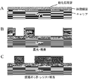
- FIGS. 8A to 8C are schematic views of a cross section of a wiring board in a process up to circuit plating and resist removal according to a specific example of a method of manufacturing a printed wiring board using the carrier-attached copper foil of the present invention.
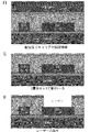
- D to F are schematic views of the cross section of the wiring board in the process from the lamination of the resin and the second-layer copper foil with a carrier to the laser drilling according to a specific example of the method for manufacturing a printed wiring board using the copper foil with a carrier of the present invention. It is.
- GI are schematic views of the cross section of the wiring board in the steps from via fill formation to first layer carrier peeling, according to a specific example of the method for producing a printed wiring board using the copper foil with carrier of the present invention.
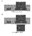
- J to K are schematic views of a cross section of a wiring board in steps from flash etching to bump / copper pillar formation according to a specific example of a method of manufacturing a printed wiring board using the carrier-attached copper foil of the present invention.
- the carrier of the present invention it is preferable to use a carrier whose Rz on the intermediate layer side surface is 0.5 ⁇ m or less. According to such a configuration, it becomes easy to control Rz of one surface or both surfaces of the intermediate layer formed on the carrier to 0.5 ⁇ m or less.
- Rz on the intermediate layer side surface of the carrier is more preferably 0.3 ⁇ m or less, and even more preferably 0.1 ⁇ m or less.
- Ra of the intermediate layer side surface of the carrier is more preferably 0.1 ⁇ m or less, still more preferably 0.08 ⁇ m or less, and even more preferably 0.05 ⁇ m or less.
- Rt on the intermediate layer side surface is 1.0 ⁇ m or less. According to such a configuration, it becomes easy to control Rt of one surface or both surfaces of the intermediate layer formed on the carrier to 1.0 ⁇ m or less.
- Rt of the intermediate layer side surface of the carrier is more preferably 0.5 ⁇ m or less, and even more preferably 0.3 ⁇ m or less.
- the carrier of the present invention it is preferable to use a film such as a resin film, and it is particularly preferable to use a film having surface smoothness.
- a film carrier in general, a heat resistant film that can withstand a thermal load during dry surface treatment, wet surface treatment, or laminating press during substrate production is preferable, and a polyimide film or the like can be used. .
- the material used for the polyimide film is not particularly limited.
- Ube Industries Upilex, DuPont / Toray DuPont Kapton, Kaneka Apical, etc. are marketed, and any polyimide film can be applied.
- the film which can be used for the carrier of this invention is not limited to such a specific kind.
- the film surface can be subjected to plasma treatment to remove contaminants on the film surface and to modify the surface.
- the adjustment can be made in the range of ⁇ 800 nm.
- by obtaining in advance the relationship between the plasma treatment conditions and the surface roughness it is possible to obtain a polyimide film having a desired surface roughness by performing plasma treatment under predetermined conditions.
- a metal foil can be used as the carrier of the present invention.
- copper foil, nickel foil, nickel alloy foil, aluminum foil, aluminum alloy foil, iron foil, iron alloy foil, zinc foil, zinc alloy foil, stainless steel foil and the like can be used.
- a copper foil can be used as the carrier of the present invention.
- the copper foil is typically provided in the form of a rolled copper foil or an electrolytic copper foil.
- the electrolytic copper foil is produced by electrolytic deposition of copper from a copper sulfate plating bath onto a drum of titanium or stainless steel, and the rolled copper foil is produced by repeating plastic working and heat treatment with a rolling roll.
- high-purity copper such as tough pitch copper (JIS H3100 alloy number C1100) and oxygen-free copper (JIS H3100 alloy number C1020)
- copper containing Sn copper containing Ag, Cr, Zr, Mg, etc.
- a copper alloy such as an added copper alloy or a Corson copper alloy added with Ni, Si, or the like can also be used.
- copper foil is also included.
- the rolled copper foil used as the carrier of the present invention can be produced by high gloss rolling. The high gloss rolling can be performed by setting the oil film equivalent defined by the following formula to 13000 to 24000.
- Oil film equivalent ⁇ (rolling oil viscosity [cSt]) ⁇ (sheet feeding speed [mpm] + roll peripheral speed [mpm]) ⁇ / ⁇ (roll biting angle [rad]) ⁇ (yield stress of material [kg / mm 2 ]) ⁇
- the rolling oil viscosity [cSt] is a kinematic viscosity at 40 ° C.
- a known method such as using a low viscosity rolling oil or slowing a sheet passing speed may be used.
- dialkylamino group-containing polymer for example, a dialkylamino group-containing polymer having the following chemical formula can be used.
- R 1 and R 2 are selected from the group consisting of a hydroxyalkyl group, an ether group, an aryl group, an aromatic substituted alkyl group, an unsaturated hydrocarbon group, and an alkyl group.
- the thickness of the carrier that can be used in the present invention is not particularly limited, but may be appropriately adjusted to a thickness suitable for serving as a carrier, for example, 25 ⁇ m or more. However, if it is too thick, the production cost becomes high, so it is generally preferable that the thickness is 50 ⁇ m or less. Accordingly, the carrier thickness is typically 12-300 ⁇ m, more typically 12-150 ⁇ m, even more typically 12-100 ⁇ m, and even more typically 25-50 ⁇ m. More typically, it is 25 to 38 ⁇ m.
- An intermediate layer is provided on the carrier. Another layer may be provided between the carrier and the intermediate layer.
- middle layer it can be set as arbitrary intermediate
- the intermediate layer is one or more of Cr, Ni, Co, Fe, Mo, Ti, W, P, Cu, Al, or an alloy thereof, a hydrate thereof, an oxide thereof, or an organic material. It is preferable to form with the layer containing.
- the intermediate layer may be composed of a plurality of layers.
- the intermediate layer is a single metal layer made of any one element of Cr, Ni, Co, Fe, Mo, Ti, W, P, Cu, and Al elements from the carrier side, Or, an alloy layer made of one or more elements selected from the element group of Cr, Ni, Co, Fe, Mo, Ti, W, P, Cu, and Al, and Cr, Ni, Co, formed thereon It is comprised from the layer which consists of a hydrate or oxide of 1 or more elements selected from the element group of Fe, Mo, Ti, W, P, Cu, and Al.
- the intermediate layer is preferably composed of two layers of a metal layer or an alloy layer and an oxide layer formed thereon.
- the metal layer or alloy layer is formed in contact with the interface with the film carrier, and the oxide layer is formed in contact with the interface with the ultrathin copper layer.
- the intermediate layer can be obtained by dry surface treatment such as sputtering, CVD and PVD, or wet surface treatment such as electroplating, electroless plating and immersion plating.
- An ultrathin copper layer is provided on the intermediate layer. Another layer may be provided between the intermediate layer and the ultrathin copper layer.
- the ultra-thin copper layer can be formed by dry plating or electroplating (wet plating) using an electrolytic bath such as copper sulfate, copper pyrophosphate, copper sulfamate, and copper cyanide.
- a copper sulfate bath is preferred because it is used in foil and copper foil can be formed at a high current density.
- an ultrathin copper layer is formed in a copper plating bath containing chlorine, an organic sulfur compound as a leveling agent, and an organic nitrogen compound as a leveling agent.
- the composition and plating conditions of a copper plating bath that can be used for wet plating in the present application are as follows.
- the thickness of the ultrathin copper layer is not particularly limited, but is generally thinner than the carrier, for example, 12 ⁇ m or less. Typically 0.5 to 12 ⁇ m, more typically 2 to 5 ⁇ m.
- the ultra thin copper layer may be provided on both sides of the carrier.
- a roughening treatment layer is provided by performing a roughening treatment, for example, for improving the adhesion to the insulating substrate.
- the roughening treatment can be performed, for example, by forming roughened particles with copper or a copper alloy.
- the roughening treatment layer is preferably composed of fine particles from the viewpoint of fine pitch formation.
- the roughening treatment layer is a layer made of any single member selected from the group consisting of copper, nickel, phosphorus, tungsten, arsenic, molybdenum, chromium, cobalt, and zinc, or a layer made of an alloy containing any one or more of them. It can be comprised with the layer containing the alloy containing any 1 type or more.
- secondary particles and tertiary particles and / or heat-resistant layer and / or rust preventive layer are formed with nickel, cobalt, copper, zinc alone or an alloy, and chromate treatment is performed on the surface.
- Treatment such as silane coupling treatment may be performed. That is, one or more layers selected from the group consisting of a heat-resistant layer, a rust-preventing layer, a chromate treatment layer, and a silane coupling treatment layer may be formed on the surface of the roughening treatment layer.
- One or more layers selected from the group consisting of a heat-resistant layer, a rust prevention layer, a chromate treatment layer, and a silane coupling treatment layer may be formed on the surface.
- the chromate-treated layer refers to a layer treated with a liquid containing chromic anhydride, chromic acid, dichromic acid, chromate or dichromate.
- Chromate treatment layer can be any element such as cobalt, iron, nickel, molybdenum, zinc, tantalum, copper, aluminum, phosphorus, tungsten, tin, arsenic and titanium (metal, alloy, oxide, nitride, sulfide, etc.) May be included).
- the chromate treatment layer examples include a chromate treatment layer treated with chromic anhydride or a potassium dichromate aqueous solution, a chromate treatment layer treated with a treatment solution containing anhydrous chromic acid or potassium dichromate and zinc, and the like. .
- the heat-resistant layer and the rust-proof layer known heat-resistant layers and rust-proof layers can be used.
- the heat-resistant layer and / or the anticorrosive layer is a group of nickel, zinc, tin, cobalt, molybdenum, copper, tungsten, phosphorus, arsenic, chromium, vanadium, titanium, aluminum, gold, silver, platinum group elements, iron, tantalum
- it may be a metal layer or an alloy layer made of one or more elements selected from the group consisting of iron, tantalum and the like.
- the heat-resistant layer and / or rust preventive layer is a group of nickel, zinc, tin, cobalt, molybdenum, copper, tungsten, phosphorus, arsenic, chromium, vanadium, titanium, aluminum, gold, silver, platinum group elements, iron, and tantalum.
- An oxide, nitride, or silicide containing one or more elements selected from the above may be included.
- the heat-resistant layer and / or the rust preventive layer may be a layer containing a nickel-zinc alloy.
- the heat-resistant layer and / or the rust preventive layer may be a nickel-zinc alloy layer.
- the nickel-zinc alloy layer may contain 50 wt% to 99 wt% nickel and 50 wt% to 1 wt% zinc, excluding inevitable impurities.
- the total adhesion amount of zinc and nickel in the nickel-zinc alloy layer may be 5 to 1000 mg / m 2 , preferably 10 to 500 mg / m 2 , preferably 20 to 100 mg / m 2 .
- the amount of nickel deposited on the layer containing the nickel-zinc alloy or the nickel-zinc alloy layer is preferably 0.5 mg / m 2 to 500 mg / m 2 , and 1 mg / m 2 to 50 mg / m 2 . More preferably.
- the heat-resistant layer and / or rust prevention layer is a layer containing a nickel-zinc alloy, the interface between the copper foil and the resin substrate is eroded by the desmear liquid when the inner wall of a through hole or via hole comes into contact with the desmear liquid. It is difficult to improve the adhesion between the copper foil and the resin substrate.
- the heat-resistant layer and / or the rust preventive layer has a nickel or nickel alloy layer with an adhesion amount of 1 mg / m 2 to 100 mg / m 2 , preferably 5 mg / m 2 to 50 mg / m 2 , and an adhesion amount of 1 mg / m 2.
- a tin layer of ⁇ 80 mg / m 2 , preferably 5 mg / m 2 ⁇ 40 mg / m 2 may be sequentially laminated.
- the nickel alloy layer may be nickel-molybdenum, nickel-zinc, nickel-molybdenum-cobalt. You may be comprised by any one of these.
- the heat-resistant layer and / or rust-preventing layer preferably has a total adhesion amount of nickel or nickel alloy and tin of 2 mg / m 2 to 150 mg / m 2 and 10 mg / m 2 to 70 mg / m 2 . It is more preferable.
- silane coupling agent for the silane coupling agent used for a silane coupling process, for example, using an amino-type silane coupling agent or an epoxy-type silane coupling agent, a mercapto-type silane coupling agent.
- Silane coupling agents include vinyltrimethoxysilane, vinylphenyltrimethoxylane, ⁇ -methacryloxypropyltrimethoxysilane, ⁇ -glycidoxypropyltrimethoxysilane, 4-glycidylbutyltrimethoxysilane, and ⁇ -aminopropyl.
- Triethoxysilane N- ⁇ (aminoethyl) ⁇ -aminopropyltrimethoxysilane, N-3- (4- (3-aminopropoxy) ptoxy) propyl-3-aminopropyltrimethoxysilane, imidazolesilane, triazinesilane, ⁇ -mercaptopropyltrimethoxysilane or the like may be used.
- the silane coupling treatment layer may be formed using a silane coupling agent such as epoxy silane, amino silane, methacryloxy silane, mercapto silane, or the like.
- a silane coupling agent such as epoxy silane, amino silane, methacryloxy silane, mercapto silane, or the like.
- you may use 2 or more types of such silane coupling agents in mixture.
- it is preferable to form using an amino-type silane coupling agent or an epoxy-type silane coupling agent.
- the amino silane coupling agent referred to here is N- (2-aminoethyl) -3-aminopropyltrimethoxysilane, 3- (N-styrylmethyl-2-aminoethylamino) propyltrimethoxysilane, 3- Aminopropyltriethoxysilane, bis (2-hydroxyethyl) -3-aminopropyltriethoxysilane, aminopropyltrimethoxysilane, N-methylaminopropyltrimethoxysilane, N-phenylaminopropyltrimethoxysilane, N- (3 -Acryloxy-2-hydroxypropyl) -3-aminopropyltriethoxysilane, 4-aminobutyltriethoxysilane, (aminoethylaminomethyl) phenethyltrimethoxysilane, N- (2-aminoethyl-3-aminopropyl
- the silane coupling treatment layer is 0.05 mg / m 2 to 200 mg / m 2 , preferably 0.15 mg / m 2 to 20 mg / m 2 , preferably 0.3 mg / m 2 to 2.0 mg in terms of silicon atoms. / M 2 is desirable. In the case of the above-mentioned range, the adhesiveness between the base resin and the surface-treated copper foil can be further improved.
- the surface of the ultrathin copper layer after various surface treatments such as roughening treatment (in the present invention, when the surface of the ultrathin copper layer is subjected to various surface treatments such as roughening treatment, "The surface of the ultrathin copper layer” and “the surface of the ultrathin copper layer” mean the surface of the ultrathin copper layer after various surface treatments such as roughening treatment). It is extremely advantageous from the viewpoint of fine pitch formation that Rz (ten-point average roughness) is 0.5 ⁇ m or less when both surfaces are measured with a non-contact type roughness meter. Rz is preferably 0.3 ⁇ m or less, and more preferably 0.1 ⁇ m or less.
- Rz is 0.0001 ⁇ m or more, such as 0.0005 ⁇ m or more, such as 0.0010 ⁇ m or more, such as 0.005 ⁇ m or more, such as 0.007 ⁇ m or more.
- the surface of the ultra-thin copper layer after various surface treatments such as roughening treatment is Ra (arithmetic mean roughness) when measured with a non-contact type roughness meter on at least one side, preferably both sides, on another side. ) Is 0.12 ⁇ m or less from the viewpoint of fine pitch formation.
- Ra is preferably 0.10 ⁇ m or less, more preferably 0.08 ⁇ m or less, and even more preferably 0.05 ⁇ m or less.
- the lower limit of Ra does not need to be set in particular.
- Ra is 0.0001 ⁇ m or more, such as 0.0005 ⁇ m or more, such as 0.0010 ⁇ m or more, such as 0.005 ⁇ m or more, such as 0.007 ⁇ m or more.
- Rt is 1.0 ⁇ m.
- the following is extremely advantageous from the viewpoint of fine pitch formation.
- Rt is preferably 0.5 ⁇ m or less, more preferably 0.3 ⁇ m or less.
- Rt is too small, the adhesive strength with the resin is reduced, and therefore it is necessary to select it appropriately in combination with the resin of the substrate to be used.
- Rt is 0.0001 ⁇ m or more, such as 0.0005 ⁇ m or more, such as 0.0010 ⁇ m or more, such as 0.005 ⁇ m or more, such as 0.007 ⁇ m or more.
- the surface of the ultrathin copper layer does not control the roughness of Rz, Ra, and Rt independently, but controls Rz and Ra, Ra and Rt, or Rz, Ra, and Rt. By doing so, it becomes possible to form a fine pitch more satisfactorily.
- Rz on the surface of the ultrathin copper layer is measured with a non-contact type roughness meter in accordance with JIS B0601-1994, and roughness parameters of Ra and Rt are measured in accordance with JIS B0601-2001.
- Resin layer on ultrathin copper layer of copper foil with carrier of the present invention (surface treatment layer formed on ultrathin copper layer by surface treatment when ultrathin copper layer is surface-treated) May be provided.
- the resin layer may be an insulating resin layer.
- the resin layer may be an adhesive resin, that is, an adhesive, or may be a semi-cured (B-stage) insulating resin layer for adhesion.
- the semi-cured state (B stage state) is a state in which there is no sticky feeling even if the surface is touched with a finger, the insulating resin layer can be stacked and stored, and a curing reaction occurs when subjected to heat treatment. Including that.
- the resin layer may contain a thermosetting resin or a thermoplastic resin.
- the resin layer may include a thermoplastic resin.
- the resin layer may contain a known resin, resin curing agent, compound, curing accelerator, dielectric, reaction catalyst, crosslinking agent, polymer, prepreg, skeleton material, and the like.
- the resin layer may be, for example, International Publication No. WO2008 / 004399, International Publication No. WO2008 / 053878, International Publication No. WO2009 / 084533, JP-A-11-5828, JP-A-11-140281, Patent 3184485, International Publication No. WO 97/02728, Japanese Patent No. 3676375, Japanese Patent Laid-Open No. 2000-43188, Japanese Patent No.
- Japanese Patent Laid-Open No. 2002-179772 Japanese Patent Laid-Open No. 2002-359444, Japanese Patent Laid-Open No. 2003-302068, Japanese Patent No. 3992225, Japanese Patent Laid-Open No. 2003 -249739, Japanese Patent No. 4136509, Japanese Patent Application Laid-Open No. 2004-82687, Japanese Patent No. 4025177, Japanese Patent Application Laid-Open No. 2004-349654, Japanese Patent No. 4286060, Japanese Patent Application Laid-Open No. 2005-262506, Japanese Patent No. 4570070, and Japanese Patent Application Laid-Open No. 4570070. No. 5-53218, Japanese Patent No. 3949676, Japanese Patent No.
- WO 2008/114858 International Publication Number WO 2009/008471, JP 2011-14727, International Publication Number WO 2009/001850, International Publication Number WO 2009/145179, International Publication Number Nos. WO2011 / 068157 and JP2013-19056 (resins, resin curing agents, compounds, curing accelerators, dielectrics, reaction catalysts, crosslinking agents, polymers, prepregs, skeletal materials, etc.) and / or You may form using the formation method and formation apparatus of a resin layer.
- a carrier-attached copper foil including a carrier, a release layer laminated on the carrier, and an ultrathin copper layer laminated on the release layer is manufactured.
- An example of the structure of the copper foil with a carrier of the present invention is shown in FIG.
- the copper foil with a carrier of the present invention shown in FIG. 1 includes a film carrier, an intermediate layer, and an ultrathin copper layer in this order.
- the ultrathin copper layer is composed of a sputtered copper layer formed by sputtering and an electrolytic copper layer formed by electrolytic plating.
- the surface of the ultrathin copper layer after the carrier-attached copper foil is attached to the resin substrate from the ultrathin copper layer side and the carrier is peeled is distinguished between the peeled surface side and the resin surface side.
- the surface of the ultra-thin copper layer is made of paper base phenol resin, paper base epoxy resin, synthetic fiber cloth base epoxy resin, glass cloth / paper composite Base epoxy resin, glass cloth / glass nonwoven fabric composite base epoxy resin and glass cloth base epoxy resin, polyester film, polyimide film, etc.
- the printed wiring board can be finally manufactured by etching the ultrathin copper layer adhered to the substrate into a desired conductor pattern.
- a printed circuit board is completed by mounting electronic components on the printed wiring board.
- the “printed wiring board” includes a printed wiring board, a printed circuit board, and a printed board on which electronic parts are mounted as described above.
- an electronic device may be manufactured using the printed wiring board, an electronic device may be manufactured using a printed circuit board on which the electronic components are mounted, and a printed circuit on which the electronic components are mounted.
- An electronic device may be manufactured using a substrate. Below, some examples of the manufacturing process of the printed wiring board using the copper foil with a carrier which concerns on this invention are shown.
- a step of preparing a copper foil with a carrier and an insulating substrate according to the present invention a step of laminating the copper foil with a carrier and an insulating substrate, and with the carrier
- a copper-clad laminate is formed through a step of peeling the carrier of the copper foil with carrier, and then a semi-additive method, a modified semi-conductor
- the semi-additive method refers to a method in which a thin electroless plating is performed on an insulating substrate or a copper foil seed layer, a pattern is formed, and then a conductive pattern is formed using electroplating and etching.
- a step of preparing a copper foil with a carrier and an insulating substrate according to the present invention Laminating the copper foil with carrier and an insulating substrate; A step of peeling the carrier of the copper foil with carrier after laminating the copper foil with carrier and the insulating substrate; Removing all of the ultrathin copper layer exposed by peeling the carrier by a method such as etching or plasma using a corrosive solution such as acid, Providing a through hole or / and a blind via in the resin exposed by removing the ultrathin copper layer by etching; Performing a desmear process on the region including the through hole or / and the blind via, Providing an electroless plating layer for the region including the resin and the through hole or / and the blind via; Providing a plating resist on the electroless plating layer; Exposing the plating resist, and then removing the plating resist in
- a step of preparing a copper foil with a carrier and an insulating substrate according to the present invention Laminating the copper foil with carrier and an insulating substrate; A step of peeling the carrier of the copper foil with carrier after laminating the copper foil with carrier and the insulating substrate; Removing all of the ultrathin copper layer exposed by peeling the carrier by a method such as etching or plasma using a corrosive solution such as acid, Providing an electroless plating layer on the surface of the resin exposed by removing the ultrathin copper layer by etching; Providing a plating resist on the electroless plating layer; Exposing the plating resist, and then removing the plating resist in a region where a circuit is formed; Providing an electrolytic plating layer in a region where the circuit from which the plating resist has been removed is formed; Removing the plating resist; Removing the electroless plating layer and the
- the modified semi-additive method is a method in which a metal foil is laminated on an insulating layer, a non-circuit forming portion is protected by a plating resist, and the copper is thickened in the circuit forming portion by electrolytic plating, and then the resist is removed. Then, a method of forming a circuit on the insulating layer by removing the metal foil other than the circuit forming portion by (flash) etching is indicated.
- the step of preparing the copper foil with carrier and the insulating substrate according to the present invention Laminating the copper foil with carrier and an insulating substrate; A step of peeling the carrier of the copper foil with carrier after laminating the copper foil with carrier and the insulating substrate; Providing a through hole or / and a blind via on the insulating substrate and the ultrathin copper layer exposed by peeling the carrier; Performing a desmear process on the region including the through hole or / and the blind via, Providing an electroless plating layer for the region including the through hole or / and the blind via; Providing a plating resist on the surface of the ultrathin copper layer exposed by peeling the carrier, Forming a circuit by electrolytic plating after providing the plating resist; Removing the plating resist; Removing the ultra-thin copper layer exposed by removing the plating resist by flash etching; including.
- the step of preparing the carrier-attached copper foil and the insulating substrate according to the present invention Laminating the copper foil with carrier and an insulating substrate; A step of peeling the carrier of the copper foil with carrier after laminating the copper foil with carrier and the insulating substrate; Providing a plating resist on the exposed ultrathin copper layer by peeling off the carrier; Exposing the plating resist, and then removing the plating resist in a region where a circuit is formed; Providing an electrolytic plating layer in a region where the circuit from which the plating resist has been removed is formed; Removing the plating resist; Removing the electroless plating layer and the ultrathin copper layer in a region other than the region where the circuit is formed by flash etching or the like; including.
- the partial additive method means that a catalyst circuit is formed on a substrate provided with a conductor layer, and if necessary, a substrate provided with holes for through holes or via holes, and etched to form a conductor circuit. Then, after providing a solder resist or a plating resist as necessary, it refers to a method of manufacturing a printed wiring board by thickening through holes, via holes, etc. on the conductor circuit by electroless plating.
- a step of preparing the copper foil with carrier and the insulating substrate according to the present invention Laminating the copper foil with carrier and an insulating substrate; A step of peeling the carrier of the copper foil with carrier after laminating the copper foil with carrier and the insulating substrate; Providing a through hole or / and a blind via on the insulating substrate and the ultrathin copper layer exposed by peeling the carrier; Performing a desmear process on the region including the through hole or / and the blind via, Applying catalyst nuclei to the region containing the through-holes and / or blind vias; Providing an etching resist on the surface of the ultrathin copper layer exposed by peeling the carrier, Exposing the etching resist to form a circuit pattern; Removing the ultrathin copper layer and the catalyst nucleus by a method such as etching or plasma using a corrosive solution such as an acid to form a circuit pattern; Removing the ultrathin copper layer and the catalyst nucleus by a method such as etch
- the subtractive method refers to a method of selectively removing unnecessary portions of the copper foil on the copper clad laminate by etching or the like to form a conductor pattern.
- a step of preparing the carrier-attached copper foil and the insulating substrate according to the present invention Laminating the copper foil with carrier and an insulating substrate; A step of peeling the carrier of the copper foil with carrier after laminating the copper foil with carrier and the insulating substrate; Providing a through hole or / and a blind via on the insulating substrate and the ultrathin copper layer exposed by peeling the carrier; Performing a desmear process on the region including the through hole or / and the blind via, Providing an electroless plating layer for the region including the through hole or / and the blind via; Providing an electroplating layer on the surface of the electroless plating layer; A step of providing an etching resist on the surface of the electrolytic plating layer or / and the ultrathin copper layer; Exposing the etching resist to form a circuit pattern; Removing the ultrathin copper layer and the electroless plating
- a step of preparing the carrier-attached copper foil and the insulating substrate according to the present invention Laminating the copper foil with carrier and an insulating substrate; A step of peeling the carrier of the copper foil with carrier after laminating the copper foil with carrier and the insulating substrate; Providing a through hole or / and a blind via on the insulating substrate and the ultrathin copper layer exposed by peeling the carrier; Performing a desmear process on the region including the through hole or / and the blind via, Providing an electroless plating layer for the region including the through hole or / and the blind via; Forming a mask on the surface of the electroless plating layer; Providing an electroplating layer on the surface of the electroless plating layer on which no mask is formed; A step of providing an etching resist on the surface of the electrolytic plating layer or / and the ultrathin copper layer; Exposing the etching resist to form
- ⁇ Through holes and / or blind vias and subsequent desmear steps may not be performed.
- the specific example of the manufacturing method of the printed wiring board using the copper foil with a carrier of this invention is demonstrated in detail using drawing.
- the carrier-attached copper foil having an ultrathin copper layer on which a roughened layer is formed will be described as an example.
- the present invention is not limited thereto, and the carrier has an ultrathin copper layer on which a roughened layer is not formed.
- the following method for producing a printed wiring board can be similarly performed using an attached copper foil.
- a copper foil with a carrier (first layer) having an ultrathin copper layer having a roughened layer formed on the surface is prepared.
- FIG. 2-A a copper foil with a carrier (first layer) having an ultrathin copper layer having a roughened layer formed on the surface is prepared.
- a resist is applied on the roughened layer of the ultrathin copper layer, exposed and developed, and etched into a predetermined shape.
- the resist is removed to form a circuit plating having a predetermined shape.
- an embedded resin is provided on the ultrathin copper layer so as to cover the circuit plating (so that the circuit plating is buried), and then the resin layer is laminated, and then another carrier is attached.
- a copper foil (second layer) is bonded from the ultrathin copper layer side.
- the carrier is peeled off from the second layer copper foil with carrier.
- the other carrier-attached copper foil may be the carrier-attached copper foil of the present invention, a conventional carrier-attached copper foil, or a normal copper foil.
- one or more circuits may be formed on the second layer circuit shown in FIG. 4-H, and these circuits may be formed by a semi-additive method, a subtractive method, a partial additive method, or a modified semi-conductor method. You may carry out by any method of an additive method.
- the copper foil with a carrier according to the present invention is preferably controlled so that the color difference on the surface of the ultrathin copper layer satisfies the following (1).
- the “color difference on the surface of the ultrathin copper layer” means the color difference on the surface of the ultrathin copper layer, or the color difference on the surface of the surface treatment layer when various surface treatments such as roughening treatment are applied. . That is, in the copper foil with a carrier according to the present invention, the color difference of the surface of the ultrathin copper layer, the roughening treatment layer, the heat resistance layer, the rust prevention layer, the chromate treatment layer or the silane coupling layer satisfies the following (1). It is preferably controlled.
- the color difference ⁇ E * ab based on JIS Z8730 on the surface of the ultrathin copper layer, the roughened layer, the heat-resistant layer, the rust-proof layer, the chromate-treated layer or the silane coupling-treated layer is 45 or more.
- the color differences ⁇ L, ⁇ a, and ⁇ b are respectively measured with a color difference meter, and are shown using the L * a * b color system based on JIS Z8730, taking into account black / white / red / green / yellow / blue. It is a comprehensive index and is expressed as ⁇ L: black and white, ⁇ a: reddish green, ⁇ b: yellow blue.
- ⁇ E * ab is expressed by the following formula using these color differences.
- the above-described color difference can be adjusted by increasing the current density when forming the ultrathin copper layer, decreasing the copper concentration in the plating solution, and increasing the linear flow rate of the plating solution.
- the above-mentioned color difference can also be adjusted by performing a roughening process on the surface of an ultra-thin copper layer and providing a roughening process layer.
- the current density is higher than that of the prior art (for example, 40 to 60 A) using an electrolytic solution containing copper and one or more elements selected from the group consisting of nickel, cobalt, tungsten, and molybdenum. / Dm 2 ) and the processing time can be shortened (for example, 0.1 to 1.3 seconds).
- Ni alloy plating (for example, Ni—W alloy plating, Ni—Co—P alloy plating, Ni—Zn alloy plating) is applied to the surface of the treatment layer or the silane coupling treatment layer at a lower current density (0.1 to 1.. 3A / dm 2 ), and the processing time can be set long (20 to 40 seconds).
- the color difference ⁇ E * ab based on JIS Z8730 on the ultrathin copper layer surface is 45 or more, for example, when forming a circuit on the ultrathin copper layer surface of the copper foil with carrier, the contrast between the ultrathin copper layer and the circuit As a result, visibility is improved and circuit alignment can be performed with high accuracy.
- the color difference ⁇ E * ab based on JIS Z8730 on the surface of the ultrathin copper layer is preferably 50 or more, more preferably 55 or more, and even more preferably 60 or more.
- the circuit plating can be accurately formed at a predetermined position. Further, according to the printed wiring board manufacturing method as described above, since the circuit plating is embedded in the resin layer, for example, removal of the ultrathin copper layer by flash etching as shown in FIG. At this time, the circuit plating is protected by the resin layer and the shape thereof is maintained, thereby facilitating the formation of a fine circuit.
- the circuit plating is protected by the resin layer, the migration resistance is improved, and the continuity of the circuit wiring is satisfactorily suppressed. For this reason, formation of a fine circuit becomes easy. Also, as shown in FIGS. 5-J and 5-K, when the ultrathin copper layer is removed by flash etching, the exposed surface of the circuit plating has a shape recessed from the resin layer, so that bumps are formed on the circuit plating. In addition, copper pillars can be easily formed thereon, and the production efficiency is improved.
- a known resin or prepreg can be used as the embedding resin (resin).
- a prepreg that is a glass cloth impregnated with BT (bismaleimide triazine) resin or BT resin, an ABF film or ABF manufactured by Ajinomoto Fine Techno Co., Ltd. can be used.
- the resin layer and / or resin and / or prepreg as described in this specification can be used for the embedding resin (resin).
- the carrier-attached copper foil used in the first layer may have a substrate or a resin layer on the surface of the carrier of the carrier-attached copper foil.
- substrate or resin layer since the copper foil with a carrier used for the first layer is supported and it becomes difficult to wrinkle, there exists an advantage that productivity improves.
- the substrate or the resin layer is not particularly limited as long as it has an effect of supporting the carrier-attached copper foil used in the first layer.
- Example 1 Production of copper foil with carrier ⁇ Example 1> A polyimide film (Upilex-S film manufactured by Ube Industries, Ltd .; thickness: 35 ⁇ m) was set in a vacuum apparatus, and after evacuation, plasma treatment was performed using oxygen. Subsequently, a Cr layer having a thickness of 10 nm was formed on one side of the plasma-treated film by Cr sputtering. Thereafter, the Cr sputtered layer was treated in a chamber in an oxygen gas atmosphere to form chromium oxide on the surface, thereby forming an intermediate layer. Further, Cu was sputtered on the surface of the Cr intermediate layer to form a Cu sputter layer having a thickness of 5 ⁇ m. The sputtering conditions were a discharge voltage of 500 V, a discharge current of 15 A, and a degree of vacuum of 5 ⁇ 10 ⁇ 2 Pa in Ar gas using a Cu target.
- the sputtering conditions were a discharge voltage of 500 V, a discharge current of 15 A, and a
- Example 2 After forming a 5 ⁇ m Cu sputtered ultrathin copper layer on a polyimide film carrier in the same steps, methods and conditions as in Example 1, the heat treatment, chromate treatment and silane coupling treatment of Example 1 were performed in this order. went.
- Example 3 After forming a 1 ⁇ m Cu sputtered layer on a polyimide carrier in the same steps, methods and conditions as in Example 1, subsequently, 2 ⁇ m by electrolytic plating on the Cu sputtered layer on a roll-to-roll type continuous plating line.
- the copper plating layer was formed, and an ultrathin copper layer having a total copper thickness of 3 ⁇ m was formed by electroplating under the following conditions to produce a copper foil with a carrier.
- Electrolytic Cu plating layer Copper concentration: 30-120 g / L H 2 SO 4 concentration: 20 to 120 g / L Cl concentration: 30-80mg / L Bis (3-sulfopropyl) disulfide disodium concentration: 10-50 mg / L Dialkylamino group-containing polymer (weight average molecular weight 8500): 10 to 50 mg / L Electrolyte temperature: 20-80 ° C Current density: 10 to 100 A / dm 2 After forming the ultrathin copper layer, the surface of the ultrathin copper layer was then subjected to the same roughening treatment 1, roughening treatment 2, heat treatment, chromate treatment, and silane coupling treatment in this order. .
- Example 4 An intermediate layer and an ultrathin copper layer were formed on the polyimide film carrier in the same steps, methods, and conditions as in Example 3. Next, the heat-resistant treatment, the chromate treatment, and the silane coupling treatment of Example 1 were performed in this order.
- Example 5 Instead of the polyimide carrier of Example 4, 1 ⁇ m in the same steps, methods and conditions as in Example 4 with respect to rolled copper foil (JX Nippon Mining & Metals Tough Pitch Copper (JIS H3100 Alloy No. C1100) foil 18 ⁇ m thickness) After forming the Cu sputtered layer, a 2 ⁇ m Cu plated layer was formed on the Cu sputtered layer by electrolytic plating on the roll-to-roll continuous plating line, and the total copper thickness was 3 ⁇ m. A layer was obtained. Next, the heat-resistant treatment, the chromate treatment, and the silane coupling treatment of Example 1 were performed in this order.
- Example 6> Instead of the polyimide carrier of Example 4, after forming a 1 ⁇ m Cu sputter layer in the same steps, methods and conditions as Example 4 for electrolytic copper foil (JX Nippon Mining & Metals HLP foil 18 ⁇ m thickness), Subsequently, on a roll-to-roll type continuous plating line, a Cu plating layer having a thickness of 2 ⁇ m was formed on the Cu sputter layer by electrolytic plating to obtain an ultrathin copper layer having a total copper thickness of 3 ⁇ m. Next, the heat-resistant treatment, the chromate treatment, and the silane coupling treatment of Example 1 were performed in this order.
- Example 7 In place of the polyimide carrier of Example 4, an intermediate layer was formed in the same steps, methods and conditions as in Example 4 with respect to rolled copper foil (JX Nippon Mining & Metals Tough Pitch Copper (JIS H3100 alloy number C1100) foil 18 ⁇ m thick). Then, a 3 ⁇ m Cu plating layer was formed on the intermediate layer by electrolytic plating on the roll-to-roll-type continuous plating line under the same method and conditions as in Example 4, and the total copper thickness was A 3 ⁇ m ultra-thin copper layer was obtained. Next, the heat-resistant treatment, the chromate treatment, and the silane coupling treatment of Example 1 were performed in this order.
- Example 8> instead of the polyimide carrier of Example 4, an intermediate layer was formed on electrolytic copper foil (JX Nippon Mining & Metals HLP foil 18 ⁇ m thick) in the same steps, methods and conditions as in Example 4, and then a roll -On a tow-roll type continuous plating line, a Cu plating layer having a thickness of 3 ⁇ m was formed on the intermediate layer by electrolytic plating, and an ultrathin copper layer having a total copper thickness of 3 ⁇ m was obtained. Next, the heat-resistant treatment, the chromate treatment, and the silane coupling treatment of Example 1 were performed in this order.
- electrolytic copper foil JX Nippon Mining & Metals HLP foil 18 ⁇ m thick
- Example 9 In place of the polyimide carrier of Example 4, an intermediate layer was formed in the same steps, methods and conditions as in Example 4 with respect to rolled copper foil (JX Nippon Mining & Metals Tough Pitch Copper (JIS H3100 alloy number C1100) foil 18 ⁇ m thick). Then, a 3 ⁇ m Cu plating layer was formed on the intermediate layer by electrolytic plating on the roll-to-roll-type continuous plating line under the same method and conditions as in Example 4, and the total copper thickness was A 3 ⁇ m ultra-thin copper layer was obtained. Next, after performing the following roughening treatment 3, the heat resistance treatment, the chromate treatment, and the silane coupling treatment of Example 1 were carried out in this order.
- Example 10> instead of the polyimide carrier of Example 4, an intermediate layer was formed on electrolytic copper foil (JX Nippon Mining & Metals HLP foil 18 ⁇ m thick) in the same steps, methods and conditions as in Example 4, and then a roll -On a tow-roll type continuous plating line, a Cu plating layer having a thickness of 3 ⁇ m was formed on the intermediate layer by electrolytic plating, and an ultrathin copper layer having a total copper thickness of 3 ⁇ m was obtained. Next, after performing the roughening treatment 3 of Example 9, the heat resistance treatment, the chromate treatment, and the silane coupling treatment of Example 1 were carried out in this order.
- electrolytic copper foil JX Nippon Mining & Metals HLP foil 18 ⁇ m thick
- Nickel sulfate 250-300 g / L Nickel chloride: 35 to 45 g / L Nickel acetate: 10-20g / L Trisodium citrate: 15-30 g / L Brightener: Saccharin, butynediol, etc.
- Sodium dodecyl sulfate 30 to 100 ppm pH: 4-6 Bath temperature: 50-70 ° C Current density: 3 to 15 A / dm 2
- Electrolytic chromate treatment Liquid composition: potassium dichromate 1-10 g / L, zinc 0-5 g / L pH: 3-4 Liquid temperature: 50-60 ° C Current density: 0.1 to 2.6 A / dm 2 Coulomb amount: 0.5 to 30 A ⁇ s / dm 2
- an ultrathin copper layer having a thickness of 3 ⁇ m was formed on the Cr layer by electroplating under the following conditions to produce a copper foil with a carrier.
- the copper foil with carrier obtained as described above was evaluated by the following method.
- Surface roughness For the carrier on which the intermediate layer is formed, the surface roughness of the intermediate layer (surface roughness on the intermediate layer forming side of the carrier) is determined using a non-contact type roughness measuring instrument (LEXT OLS4000 manufactured by Olympus). Measured according to JIS B0601-2001, and Rz was measured according to JIS B0601-1994.
- Ra and Rt are compliant with JIS B0601-2001 using a non-contact type roughness measuring machine (LEX OLS4000 manufactured by Olympus), and Rz was measured according to JIS B0601-1994.
- Circuit formability Each copper foil with a carrier was laminated and pressed on an epoxy resin, and then the carrier was peeled and removed. 0.3 ⁇ m of the exposed ultrathin copper layer was removed by soft etching. Then, after washing and drying, a dry film resist (manufactured by Hitachi Chemical Co., Ltd., trade name RY-3625) was laminated on the ultrathin copper layer. Exposure was performed at 15 mJ / cm 2 , and liquid jet rocking was performed at 38 ° C. for 1 minute using a developer (sodium carbonate) to form resist patterns of various lines / spaces.
Landscapes
- Chemical & Material Sciences (AREA)
- Engineering & Computer Science (AREA)
- Chemical Kinetics & Catalysis (AREA)
- Electrochemistry (AREA)
- Materials Engineering (AREA)
- Metallurgy (AREA)
- Organic Chemistry (AREA)
- Laminated Bodies (AREA)
- Parts Printed On Printed Circuit Boards (AREA)
- Microelectronics & Electronic Packaging (AREA)
- Manufacturing & Machinery (AREA)
- Electroplating Methods And Accessories (AREA)
Abstract
Priority Applications (3)
| Application Number | Priority Date | Filing Date | Title |
|---|---|---|---|
| KR1020157027336A KR20150126008A (ko) | 2013-03-04 | 2014-03-04 | 캐리어 부착 동박, 그것을 사용한 구리 피복 적층판, 프린트 배선판, 전자 기기 및 프린트 배선판의 제조 방법 |
| CN201480012569.8A CN105209252B (zh) | 2013-03-04 | 2014-03-04 | 附载体铜箔、使用其的覆铜积层板、印刷配线板、电子机器及印刷配线板的制造方法 |
| JP2015504333A JP6514635B2 (ja) | 2013-03-04 | 2014-03-04 | キャリア付銅箔、それを用いた銅張積層板、プリント配線板、電子機器及びプリント配線板の製造方法 |
Applications Claiming Priority (2)
| Application Number | Priority Date | Filing Date | Title |
|---|---|---|---|
| JP2013042076 | 2013-03-04 | ||
| JP2013-042076 | 2013-03-04 |
Publications (1)
| Publication Number | Publication Date |
|---|---|
| WO2014136785A1 true WO2014136785A1 (fr) | 2014-09-12 |
Family
ID=51491300
Family Applications (1)
| Application Number | Title | Priority Date | Filing Date |
|---|---|---|---|
| PCT/JP2014/055494 WO2014136785A1 (fr) | 2013-03-04 | 2014-03-04 | Feuille de cuivre ayant un porteur fixé sur cette dernière, stratifié plaqué de cuivre l'utilisant, carte de circuits imprimés, dispositif électronique et procédé de fabrication d'une carte de circuits imprimés |
Country Status (5)
| Country | Link |
|---|---|
| JP (1) | JP6514635B2 (fr) |
| KR (1) | KR20150126008A (fr) |
| CN (2) | CN105209252B (fr) |
| TW (1) | TW201446495A (fr) |
| WO (1) | WO2014136785A1 (fr) |
Cited By (6)
| Publication number | Priority date | Publication date | Assignee | Title |
|---|---|---|---|---|
| JP2016084533A (ja) * | 2014-10-22 | 2016-05-19 | Jx金属株式会社 | 表面処理金属材、キャリア付金属箔、コネクタ、端子、積層体、シールドテープ、シールド材、プリント配線板、金属加工部材、電子機器の製造方法、及び、プリント配線板の製造方法 |
| CN106028633A (zh) * | 2015-03-31 | 2016-10-12 | 新日铁住金化学株式会社 | 覆铜层压板及印刷配线板 |
| JP2017019207A (ja) * | 2015-07-10 | 2017-01-26 | 株式会社カネカ | 金属細線フィルムおよびその製造方法 |
| TWI572726B (zh) * | 2014-09-19 | 2017-03-01 | Mitsui Mining & Smelting Co | Surface treatment copper foil and its manufacturing method, printed wiring board with copper laminated board and printed wiring board |
| JP2018026589A (ja) * | 2015-08-06 | 2018-02-15 | Jx金属株式会社 | キャリア付銅箔、積層体、プリント配線板の製造方法及び電子機器の製造方法 |
| US10178775B2 (en) | 2015-01-21 | 2019-01-08 | Jx Nippon Mining & Metals Corporation | Copper foil provided with carrier, laminate, printed wiring board, and method for fabricating printed wiring board |
Families Citing this family (4)
| Publication number | Priority date | Publication date | Assignee | Title |
|---|---|---|---|---|
| WO2017141983A1 (fr) * | 2016-02-18 | 2017-08-24 | 三井金属鉱業株式会社 | Procédé de fabrication de carte de circuit imprimé |
| KR102661275B1 (ko) * | 2017-10-26 | 2024-04-29 | 미쓰이금속광업주식회사 | 극박 구리박 및 캐리어 구비 극박 구리박, 그리고 프린트 배선판의 제조 방법 |
| JP6836689B2 (ja) | 2018-03-29 | 2021-03-03 | 三井金属鉱業株式会社 | ガラスキャリア付銅箔及びその製造方法 |
| WO2020173574A1 (fr) | 2019-02-28 | 2020-09-03 | Circuit Foil Luxembourg | Feuille de cuivre composite et son procédé de fabrication |
Citations (6)
| Publication number | Priority date | Publication date | Assignee | Title |
|---|---|---|---|---|
| JP2004169181A (ja) * | 2002-10-31 | 2004-06-17 | Furukawa Techno Research Kk | キャリア付き極薄銅箔、及びその製造方法、キャリア付き極薄銅箔を用いたプリント配線基板 |
| JP2005076091A (ja) * | 2003-09-01 | 2005-03-24 | Furukawa Circuit Foil Kk | キャリア付き極薄銅箔の製造方法、及びその製造方法で製造されたキャリア付き極薄銅箔 |
| JP2007186782A (ja) * | 2005-12-15 | 2007-07-26 | Furukawa Circuit Foil Kk | キャリア付き極薄銅箔及びプリント配線基板 |
| JP2010222657A (ja) * | 2009-03-24 | 2010-10-07 | Mitsui Mining & Smelting Co Ltd | キャリア箔付電解銅箔、キャリア箔付電解銅箔の製造方法及びそのキャリア箔付電解銅箔を用いて得られる銅張積層板 |
| JP2011176051A (ja) * | 2010-02-23 | 2011-09-08 | Dainippon Printing Co Ltd | 配線回路基板用基材、配線回路基板用基材の製造方法、配線回路基板、配線回路基板の製造方法、hdd用サスペンション基板、hdd用サスペンションおよびハードディスクドライブ |
| WO2014042201A1 (fr) * | 2012-09-11 | 2014-03-20 | Jx日鉱日石金属株式会社 | Feuille de cuivre pourvue d'un support |
Family Cites Families (5)
| Publication number | Priority date | Publication date | Assignee | Title |
|---|---|---|---|---|
| JP4006618B2 (ja) * | 2001-09-26 | 2007-11-14 | 日鉱金属株式会社 | キャリア付銅箔の製法及びキャリア付銅箔を使用したプリント基板 |
| TW200420208A (en) * | 2002-10-31 | 2004-10-01 | Furukawa Circuit Foil | Ultra-thin copper foil with carrier, method of production of the same, and printed circuit board using ultra-thin copper foil with carrier |
| JP4087369B2 (ja) * | 2003-11-11 | 2008-05-21 | 古河サーキットフォイル株式会社 | キャリア付き極薄銅箔、およびプリント配線板 |
| JP4570070B2 (ja) * | 2004-03-16 | 2010-10-27 | 三井金属鉱業株式会社 | 絶縁層形成用の樹脂層を備えたキャリア箔付電解銅箔、銅張積層板、プリント配線板、多層銅張積層板の製造方法及びプリント配線板の製造方法 |
| WO2006106956A1 (fr) * | 2005-03-31 | 2006-10-12 | Mitsui Mining & Smelting Co., Ltd | Feuille de cuivre électrolytique et procédé de production d'une feuille de cuivre électrolytique, feuille de cuivre électrolytique traitée en surface utilisant ladite feuille de cuivre électrolytique et plaque stratifiée recouverte de cuivre et carte de circuit im |
-
2014
- 2014-03-04 WO PCT/JP2014/055494 patent/WO2014136785A1/fr active Application Filing
- 2014-03-04 CN CN201480012569.8A patent/CN105209252B/zh active Active
- 2014-03-04 TW TW103107351A patent/TW201446495A/zh unknown
- 2014-03-04 JP JP2015504333A patent/JP6514635B2/ja active Active
- 2014-03-04 KR KR1020157027336A patent/KR20150126008A/ko not_active Application Discontinuation
- 2014-03-04 CN CN201611113446.0A patent/CN107031143A/zh active Pending
Patent Citations (6)
| Publication number | Priority date | Publication date | Assignee | Title |
|---|---|---|---|---|
| JP2004169181A (ja) * | 2002-10-31 | 2004-06-17 | Furukawa Techno Research Kk | キャリア付き極薄銅箔、及びその製造方法、キャリア付き極薄銅箔を用いたプリント配線基板 |
| JP2005076091A (ja) * | 2003-09-01 | 2005-03-24 | Furukawa Circuit Foil Kk | キャリア付き極薄銅箔の製造方法、及びその製造方法で製造されたキャリア付き極薄銅箔 |
| JP2007186782A (ja) * | 2005-12-15 | 2007-07-26 | Furukawa Circuit Foil Kk | キャリア付き極薄銅箔及びプリント配線基板 |
| JP2010222657A (ja) * | 2009-03-24 | 2010-10-07 | Mitsui Mining & Smelting Co Ltd | キャリア箔付電解銅箔、キャリア箔付電解銅箔の製造方法及びそのキャリア箔付電解銅箔を用いて得られる銅張積層板 |
| JP2011176051A (ja) * | 2010-02-23 | 2011-09-08 | Dainippon Printing Co Ltd | 配線回路基板用基材、配線回路基板用基材の製造方法、配線回路基板、配線回路基板の製造方法、hdd用サスペンション基板、hdd用サスペンションおよびハードディスクドライブ |
| WO2014042201A1 (fr) * | 2012-09-11 | 2014-03-20 | Jx日鉱日石金属株式会社 | Feuille de cuivre pourvue d'un support |
Cited By (10)
| Publication number | Priority date | Publication date | Assignee | Title |
|---|---|---|---|---|
| TWI572726B (zh) * | 2014-09-19 | 2017-03-01 | Mitsui Mining & Smelting Co | Surface treatment copper foil and its manufacturing method, printed wiring board with copper laminated board and printed wiring board |
| JP2016084533A (ja) * | 2014-10-22 | 2016-05-19 | Jx金属株式会社 | 表面処理金属材、キャリア付金属箔、コネクタ、端子、積層体、シールドテープ、シールド材、プリント配線板、金属加工部材、電子機器の製造方法、及び、プリント配線板の製造方法 |
| US10178775B2 (en) | 2015-01-21 | 2019-01-08 | Jx Nippon Mining & Metals Corporation | Copper foil provided with carrier, laminate, printed wiring board, and method for fabricating printed wiring board |
| CN106028633A (zh) * | 2015-03-31 | 2016-10-12 | 新日铁住金化学株式会社 | 覆铜层压板及印刷配线板 |
| JP2016193501A (ja) * | 2015-03-31 | 2016-11-17 | 新日鉄住金化学株式会社 | 銅張積層板及びプリント配線板 |
| CN106028633B (zh) * | 2015-03-31 | 2019-09-10 | 日铁化学材料株式会社 | 覆铜层压板及印刷配线板 |
| JP2017019207A (ja) * | 2015-07-10 | 2017-01-26 | 株式会社カネカ | 金属細線フィルムおよびその製造方法 |
| JP2018026589A (ja) * | 2015-08-06 | 2018-02-15 | Jx金属株式会社 | キャリア付銅箔、積層体、プリント配線板の製造方法及び電子機器の製造方法 |
| JP2018026590A (ja) * | 2015-08-06 | 2018-02-15 | Jx金属株式会社 | キャリア付銅箔、積層体、プリント配線板の製造方法及び電子機器の製造方法 |
| JP2018074153A (ja) * | 2015-08-06 | 2018-05-10 | Jx金属株式会社 | キャリア付銅箔、積層体、プリント配線板の製造方法及び電子機器の製造方法 |
Also Published As
| Publication number | Publication date |
|---|---|
| JPWO2014136785A1 (ja) | 2017-02-16 |
| TW201446495A (zh) | 2014-12-16 |
| KR20150126008A (ko) | 2015-11-10 |
| TWI562885B (fr) | 2016-12-21 |
| JP6514635B2 (ja) | 2019-05-15 |
| CN105209252B (zh) | 2018-01-30 |
| CN105209252A (zh) | 2015-12-30 |
| CN107031143A (zh) | 2017-08-11 |
Similar Documents
| Publication | Publication Date | Title |
|---|---|---|
| WO2014136785A1 (fr) | Feuille de cuivre ayant un porteur fixé sur cette dernière, stratifié plaqué de cuivre l'utilisant, carte de circuits imprimés, dispositif électronique et procédé de fabrication d'une carte de circuits imprimés | |
| JP5481577B1 (ja) | キャリア付き銅箔 | |
| JP6403969B2 (ja) | キャリア付銅箔、プリント配線板、銅張積層板、電子機器及びプリント配線板の製造方法 | |
| JP6640567B2 (ja) | キャリア付銅箔、積層体、プリント配線板、電子機器の製造方法及びプリント配線板の製造方法 | |
| JP6591893B2 (ja) | キャリア付銅箔、銅張積層板、プリント配線板、電子機器、樹脂層、キャリア付銅箔の製造方法、及びプリント配線板の製造方法 | |
| WO2014157728A1 (fr) | Feuille de cuivre ayant un support, carte de circuit imprimé, feuille stratifiée à revêtement de cuivre, dispositif électronique, et procédé de fabrication de carte de circuit imprimé | |
| JP2015199355A (ja) | キャリア付銅箔、プリント配線板、積層体、積層板、電子機器及びプリント配線板の製造方法 | |
| WO2014192895A1 (fr) | Feuille de cuivre, feuille de cuivre comprenant un support, stratifié recouvert de cuivre, carte de circuit imprimé, substrat de formation de circuit destiné à un boîtier semi-conducteur, boîtier semi-conducteur, dispositif électronique, substrat en résine, procédé de formation de circuit, procédé semi-additif, et procédé de fabrication de carte de circuit imprimé | |
| JP6353193B2 (ja) | キャリア付き銅箔、当該キャリア付き銅箔を用いて銅張積層板を製造する方法、当該キャリア付き銅箔を用いてプリント配線板を製造する方法、及びプリント配線板の製造方法 | |
| JP2016194112A (ja) | キャリア付金属箔、積層体、プリント配線板、電子機器、キャリア付金属箔の製造方法及びプリント配線板の製造方法 | |
| JP2014208484A (ja) | キャリア付銅箔、プリント配線板、銅張積層板、電子機器及びプリント配線板の製造方法 | |
| JP6438208B2 (ja) | キャリア付銅箔、それを用いた銅張積層板、プリント配線板、電子機器及びプリント配線板の製造方法 | |
| JP5298252B1 (ja) | キャリア付銅箔、キャリア付銅箔の製造方法、プリント配線板、プリント回路板、銅張積層板、及び、プリント配線板の製造方法 | |
| JP2014208909A (ja) | キャリア付銅箔、プリント配線板、銅張積層板、電子機器及びプリント配線板の製造方法 | |
| JP2014208481A (ja) | キャリア付銅箔、プリント配線板、銅張積層板、電子機器及びプリント配線板の製造方法 | |
| JP6425399B2 (ja) | キャリア付銅箔、プリント配線板、プリント回路板、銅張積層板及びプリント配線板の製造方法 | |
| JP5481591B1 (ja) | キャリア付き銅箔 | |
| JP2014208485A (ja) | キャリア付銅箔、プリント配線板、銅張積層板、電子機器及びプリント配線板の製造方法 | |
| JP6842232B2 (ja) | キャリア付金属箔、積層体、プリント配線板、電子機器、キャリア付金属箔の製造方法及びプリント配線板の製造方法 | |
| JP2014210427A (ja) | キャリア付銅箔、プリント配線板、銅張積層板、電子機器及びプリント配線板の製造方法 | |
| JP5481586B1 (ja) | キャリア付銅箔、キャリア付銅箔の製造方法、プリント配線板、プリント回路板、銅張積層板、及びプリント配線板の製造方法 | |
| JP6329727B2 (ja) | キャリア付銅箔、キャリア付銅箔の製造方法、プリント配線板、プリント回路板、銅張積層板、及び、プリント配線板の製造方法 | |
| WO2018207788A1 (fr) | Feuille de cuivre électrolytique, son procédé de production, stratifié cuivré, carte de circuit imprimé, son procédé de production, dispositif électronique et son procédé de production | |
| WO2018207785A1 (fr) | Feuille de cuivre électrolytique et son procédé de production, stratifié cuivré, carte de circuit imprimé et son procédé de production, dispositif électronique et son procédé de production | |
| JP2014208482A (ja) | キャリア付銅箔、プリント配線板、銅張積層板、電子機器及びプリント配線板の製造方法 |
Legal Events
| Date | Code | Title | Description |
|---|---|---|---|
| 121 | Ep: the epo has been informed by wipo that ep was designated in this application |
Ref document number: 14760759 Country of ref document: EP Kind code of ref document: A1 |
|
| ENP | Entry into the national phase |
Ref document number: 2015504333 Country of ref document: JP Kind code of ref document: A |
|
| NENP | Non-entry into the national phase |
Ref country code: DE |
|
| ENP | Entry into the national phase |
Ref document number: 20157027336 Country of ref document: KR Kind code of ref document: A |
|
| 122 | Ep: pct application non-entry in european phase |
Ref document number: 14760759 Country of ref document: EP Kind code of ref document: A1 |