WO2014136706A1 - 被検体観察システム及び方法 - Google Patents
被検体観察システム及び方法 Download PDFInfo
- Publication number
- WO2014136706A1 WO2014136706A1 PCT/JP2014/055235 JP2014055235W WO2014136706A1 WO 2014136706 A1 WO2014136706 A1 WO 2014136706A1 JP 2014055235 W JP2014055235 W JP 2014055235W WO 2014136706 A1 WO2014136706 A1 WO 2014136706A1
- Authority
- WO
- WIPO (PCT)
- Prior art keywords
- light
- observation
- wavelength
- image
- illumination
- Prior art date
Links
Images


Classifications
-
- A—HUMAN NECESSITIES
- A61—MEDICAL OR VETERINARY SCIENCE; HYGIENE
- A61B—DIAGNOSIS; SURGERY; IDENTIFICATION
- A61B1/00—Instruments for performing medical examinations of the interior of cavities or tubes of the body by visual or photographical inspection, e.g. endoscopes; Illuminating arrangements therefor
- A61B1/06—Instruments for performing medical examinations of the interior of cavities or tubes of the body by visual or photographical inspection, e.g. endoscopes; Illuminating arrangements therefor with illuminating arrangements
- A61B1/0653—Instruments for performing medical examinations of the interior of cavities or tubes of the body by visual or photographical inspection, e.g. endoscopes; Illuminating arrangements therefor with illuminating arrangements with wavelength conversion
-
- A—HUMAN NECESSITIES
- A61—MEDICAL OR VETERINARY SCIENCE; HYGIENE
- A61B—DIAGNOSIS; SURGERY; IDENTIFICATION
- A61B1/00—Instruments for performing medical examinations of the interior of cavities or tubes of the body by visual or photographical inspection, e.g. endoscopes; Illuminating arrangements therefor
- A61B1/00002—Operational features of endoscopes
- A61B1/00004—Operational features of endoscopes characterised by electronic signal processing
- A61B1/00009—Operational features of endoscopes characterised by electronic signal processing of image signals during a use of endoscope
- A61B1/000094—Operational features of endoscopes characterised by electronic signal processing of image signals during a use of endoscope extracting biological structures
-
- A—HUMAN NECESSITIES
- A61—MEDICAL OR VETERINARY SCIENCE; HYGIENE
- A61B—DIAGNOSIS; SURGERY; IDENTIFICATION
- A61B1/00—Instruments for performing medical examinations of the interior of cavities or tubes of the body by visual or photographical inspection, e.g. endoscopes; Illuminating arrangements therefor
- A61B1/04—Instruments for performing medical examinations of the interior of cavities or tubes of the body by visual or photographical inspection, e.g. endoscopes; Illuminating arrangements therefor combined with photographic or television appliances
- A61B1/043—Instruments for performing medical examinations of the interior of cavities or tubes of the body by visual or photographical inspection, e.g. endoscopes; Illuminating arrangements therefor combined with photographic or television appliances for fluorescence imaging
-
- A—HUMAN NECESSITIES
- A61—MEDICAL OR VETERINARY SCIENCE; HYGIENE
- A61B—DIAGNOSIS; SURGERY; IDENTIFICATION
- A61B1/00—Instruments for performing medical examinations of the interior of cavities or tubes of the body by visual or photographical inspection, e.g. endoscopes; Illuminating arrangements therefor
- A61B1/04—Instruments for performing medical examinations of the interior of cavities or tubes of the body by visual or photographical inspection, e.g. endoscopes; Illuminating arrangements therefor combined with photographic or television appliances
- A61B1/045—Control thereof
-
- A—HUMAN NECESSITIES
- A61—MEDICAL OR VETERINARY SCIENCE; HYGIENE
- A61B—DIAGNOSIS; SURGERY; IDENTIFICATION
- A61B1/00—Instruments for performing medical examinations of the interior of cavities or tubes of the body by visual or photographical inspection, e.g. endoscopes; Illuminating arrangements therefor
- A61B1/06—Instruments for performing medical examinations of the interior of cavities or tubes of the body by visual or photographical inspection, e.g. endoscopes; Illuminating arrangements therefor with illuminating arrangements
- A61B1/0638—Instruments for performing medical examinations of the interior of cavities or tubes of the body by visual or photographical inspection, e.g. endoscopes; Illuminating arrangements therefor with illuminating arrangements providing two or more wavelengths
-
- A—HUMAN NECESSITIES
- A61—MEDICAL OR VETERINARY SCIENCE; HYGIENE
- A61B—DIAGNOSIS; SURGERY; IDENTIFICATION
- A61B1/00—Instruments for performing medical examinations of the interior of cavities or tubes of the body by visual or photographical inspection, e.g. endoscopes; Illuminating arrangements therefor
- A61B1/06—Instruments for performing medical examinations of the interior of cavities or tubes of the body by visual or photographical inspection, e.g. endoscopes; Illuminating arrangements therefor with illuminating arrangements
- A61B1/0655—Control therefor
-
- A—HUMAN NECESSITIES
- A61—MEDICAL OR VETERINARY SCIENCE; HYGIENE
- A61B—DIAGNOSIS; SURGERY; IDENTIFICATION
- A61B5/00—Measuring for diagnostic purposes; Identification of persons
- A61B5/0059—Measuring for diagnostic purposes; Identification of persons using light, e.g. diagnosis by transillumination, diascopy, fluorescence
- A61B5/0071—Measuring for diagnostic purposes; Identification of persons using light, e.g. diagnosis by transillumination, diascopy, fluorescence by measuring fluorescence emission
-
- A—HUMAN NECESSITIES
- A61—MEDICAL OR VETERINARY SCIENCE; HYGIENE
- A61B—DIAGNOSIS; SURGERY; IDENTIFICATION
- A61B5/00—Measuring for diagnostic purposes; Identification of persons
- A61B5/145—Measuring characteristics of blood in vivo, e.g. gas concentration, pH value; Measuring characteristics of body fluids or tissues, e.g. interstitial fluid, cerebral tissue
- A61B5/14546—Measuring characteristics of blood in vivo, e.g. gas concentration, pH value; Measuring characteristics of body fluids or tissues, e.g. interstitial fluid, cerebral tissue for measuring analytes not otherwise provided for, e.g. ions, cytochromes
-
- A—HUMAN NECESSITIES
- A61—MEDICAL OR VETERINARY SCIENCE; HYGIENE
- A61B—DIAGNOSIS; SURGERY; IDENTIFICATION
- A61B5/00—Measuring for diagnostic purposes; Identification of persons
- A61B5/145—Measuring characteristics of blood in vivo, e.g. gas concentration, pH value; Measuring characteristics of body fluids or tissues, e.g. interstitial fluid, cerebral tissue
- A61B5/1455—Measuring characteristics of blood in vivo, e.g. gas concentration, pH value; Measuring characteristics of body fluids or tissues, e.g. interstitial fluid, cerebral tissue using optical sensors, e.g. spectral photometrical oximeters
-
- A—HUMAN NECESSITIES
- A61—MEDICAL OR VETERINARY SCIENCE; HYGIENE
- A61B—DIAGNOSIS; SURGERY; IDENTIFICATION
- A61B1/00—Instruments for performing medical examinations of the interior of cavities or tubes of the body by visual or photographical inspection, e.g. endoscopes; Illuminating arrangements therefor
- A61B1/00002—Operational features of endoscopes
- A61B1/0002—Operational features of endoscopes provided with data storages
-
- A—HUMAN NECESSITIES
- A61—MEDICAL OR VETERINARY SCIENCE; HYGIENE
- A61B—DIAGNOSIS; SURGERY; IDENTIFICATION
- A61B1/00—Instruments for performing medical examinations of the interior of cavities or tubes of the body by visual or photographical inspection, e.g. endoscopes; Illuminating arrangements therefor
- A61B1/06—Instruments for performing medical examinations of the interior of cavities or tubes of the body by visual or photographical inspection, e.g. endoscopes; Illuminating arrangements therefor with illuminating arrangements
- A61B1/0661—Endoscope light sources
- A61B1/0684—Endoscope light sources using light emitting diodes [LED]
Definitions
- the present invention relates to an object observation system and method for performing a plurality of observations such as normal observation using white light and light having a wavelength different from that in normal observation, for example, observation using special light for observing a specific object. About.
- an object observation system such as an endoscope includes a light emitting device for irradiating the object with white light or the like.
- a light emitting device there is currently a device that changes a light into a desired irradiation pattern or color by arranging a wavelength conversion member at the tip of an optical fiber and converting the wavelength of light output from a small solid light source by the wavelength conversion member.
- Patent Document 1 discloses a light emitting device capable of emitting various colors by combining a pumping light source and a wavelength conversion member disposed at the tip of an optical fiber, and an endoscope device using the light emitting device.
- Patent Document 1 a plurality of wavelength conversion members arranged at the tip are excited by an excitation light source, and white light generated by the excitation, that is, white light having a spectral component in a wide range of a visible light region, is emitted from an endoscope light source.
- the normal light observation in the living body is realized by irradiating the living body with the white light.
- Patent Document 1 when light having a different color from white light, that is, light having a different wavelength is emitted, it is realized by exciting a wavelength conversion member having different emission characteristics with an excitation light source.
- Patent Document 1 when performing a plurality of observations such as normal light observation using white light and observation using a color different from white light, it is necessary to arrange a plurality of wavelength conversion members having different emission characteristics at the tip.
- a plurality of light guide members for guiding excitation light from the excitation light source to the wavelength conversion member and a plurality of excitation light sources are necessary depending on the case, and it is difficult to reduce the size of the light emitting device or the like.
- the present invention provides an object observation system and method that can be used for a plurality of observations such as normal light observation and special light observation, and that can achieve downsizing that can obtain an image in a desired wavelength band. Objective.
- An object observation system includes a plurality of primary light sources, a wavelength conversion unit that wavelength-converts a plurality of primary lights having different wavelengths emitted from the plurality of primary light sources, When a plurality of illumination lights including light that has been wavelength-converted by the wavelength conversion unit is irradiated onto an observation target, an image acquisition unit that acquires an image of the irradiation region of the illumination light on the observation target by performing color separation using a plurality of color regions And a mode input unit capable of inputting a plurality of observation modes, and a special light observation mode for highlighting a specific observation target among the observation targets is input to the mode input unit.
- a light source unit that sequentially lights up and sequentially irradiates the observation target with respect to the observation target from an opening at the same location, and the image acquisition unit is configured to irradiate the observation target with each of the plurality of illumination lights.
- Multiple drawings Acquires generates a special light observation image of the observation target based on the plurality of images.
- An object observation method wavelength-converts a plurality of primary lights having different wavelengths respectively emitted from a plurality of primary light sources, and observes a plurality of illumination lights including the wavelength-converted light.
- the special light observation mode for irradiating the object obtaining an image of the irradiation area of the illumination light in the observation object by color separation using a plurality of color regions, and highlighting a specific observation object among the observation objects,
- a plurality of primary light sources are sequentially turned on, and the illumination light is sequentially applied to the observation target from an opening at the same location, and a plurality of images are acquired each time the plurality of illumination lights are applied to the observation target.
- the special light observation image of the observation target is generated based on the plurality of images.
- an object observation system and method that can be used for a plurality of observations such as normal light observation and special light observation and that can realize downsizing that can obtain an image of a desired wavelength band.
- FIG. 1 is a configuration diagram showing a first embodiment of an object observation system according to the present invention.
- FIG. 2 is a schematic configuration diagram showing a wavelength conversion unit in the apparatus.
- FIG. 3 is a diagram showing the excitation / fluorescence spectrum characteristics of the oxide phosphor forming the wavelength conversion member in the apparatus.
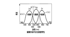
- FIG. 4 is a diagram showing sensitivity wavelength characteristics of a CCD imager used for imaging means in the apparatus.
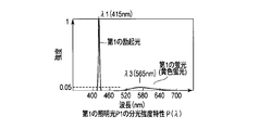
- FIG. 5 is a diagram showing the spectral characteristics of the first illumination light emitted from the wavelength conversion unit in the apparatus.
- FIG. 6 is a diagram showing the spectral characteristics of the second illumination light emitted from the wavelength conversion unit in the apparatus.
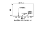
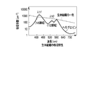
- FIG. 7 is a diagram showing an absorption coefficient serving as an index of the absorption intensity of hemoglobin flowing in the blood vessel K in the biological tissue in the apparatus.
- FIG. 8 is a diagram showing a portion corresponding to the second narrowband spectral element in which the light receiving sensitivity characteristic of the G pixel of the image pickup unit and the wavelength spectrum of yellow fluorescence overlap in the same apparatus.
- FIG. 9 is a block diagram showing a wavelength conversion unit in the second embodiment of the subject observation system according to the present invention.
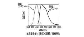
- FIG. 10 is a diagram showing the absorption / fluorescence characteristics of the wavelength conversion member (green) in the apparatus.
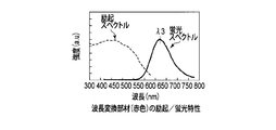
- FIG. 11 is a diagram showing the absorption / fluorescence characteristics of the wavelength conversion member (red) in the apparatus.
- FIG. 12 is a block diagram showing a wavelength conversion unit in the third embodiment of the subject observation system according to the present invention.
- the blue (B) region is a wavelength region of 380 nm to 500 nm.
- the green (G) region is a wavelength region of 500 nm to 600 nm.
- the red (R) region is a wavelength region of 600 nm to 720 nm.
- the wavelengths at which the sensitivity of the blue pixel, the green pixel, and the red pixel of the imaging unit 30 are maximized are included in the blue region, the green region, and the red region, respectively.
- FIG. 1 is a configuration diagram of a subject observation apparatus 1 including a light source device.
- the subject observation apparatus 1 observes an observation target in a subject Q such as a living body, for example, hemoglobin flowing in the blood vessel K, for example.
- the subject Q is, for example, a human body or the like, and is a biological tissue including blood vessels (including capillaries, deep blood vessels, etc.) K.
- the subject observation apparatus 1 has a plurality of observation modes, for example, a normal light observation mode and a special light observation mode. In the normal light observation mode, observation is performed by irradiating the subject Q with white light. In the special light observation mode, a specific observation target among the observation targets is highlighted.
- the subject observation apparatus 1 includes a light source device 2 that irradiates the subject Q with the first or second illumination light P1 or P2 as the illumination light P, an image acquisition device 3 that acquires image information of the subject Q, and a light source.
- the system control part 4 which controls the apparatus 2 and the image acquisition apparatus 3 is included.
- the light source device 2 includes a plurality of excitation light sources as a plurality of primary light sources and a wavelength conversion unit.
- the plurality of excitation light sources output primary light having a plurality of different wavelengths.
- the wavelength conversion unit receives the primary light output from the plurality of excitation light sources, converts the wavelength, and emits the illumination light P including the wavelength-converted light to the observation target.
- the light source device 2 includes a plurality of excitation light sources (primary light sources) that emit a plurality of excitation lights each having a different spectrum.
- the plurality of excitation light sources include, for example, a first laser diode 5 that is a semiconductor laser as a first excitation light source, and a second laser diode 6 that is a semiconductor laser as a second excitation light source.
- the first laser diode 5 emits a blue-violet laser beam in a narrow band with a center wavelength (first spectrum) as an emission peak of 415 nm ( ⁇ 1) and a half-value width of several nm or less as a first primary light ( The first excitation light is emitted.
- the second laser diode 6 has a second primary light (blue laser light having a narrow band with a center wavelength (second spectrum) of an emission peak of 445 nm ( ⁇ 2) and a half-value width of several nanometers or less.
- the second excitation light is emitted.
- Each laser beam (first and second excitation light) emitted from the first and second laser diodes 5 and 6 exists in the blue region.
- the wavelengths ⁇ 1 and ⁇ 2 of the laser beams emitted from the laser diodes 5 and 6 are center values of 415 nm ( ⁇ 1) and 445 nm ( ⁇ 2), which are emission peaks, respectively, but are limited to these center wavelengths. However, there may be variations and individual differences as long as the operational effects of the present embodiment can be maintained.
- the first and second laser diodes 5 and 6 are connected to the light source control unit 7 and are driven and controlled by the light source control unit 7. Details of drive control of the first and second laser diodes 5 and 6 by the light source controller 7 will be described later.
- One incident end of the optical coupler 9 is optically connected to the first laser diode 5 through the first optical fiber 8.
- the first optical fiber 8 guides the blue-violet laser light emitted from the first laser diode 5 to the optical coupler 9.
- the other incident end of the optical coupler 9 is optically connected to the second laser diode 6 through the second optical fiber 10.
- the second optical fiber 10 guides the blue laser light emitted from the second laser diode 6 to the optical coupler 9.
- the output end of the optical coupler 9 is optically connected to the wavelength conversion unit 12 via the third optical fiber 11.
- the optical coupler 9 emits blue-violet laser light guided by the first optical fiber 8 as first primary light (excitation light) or blue laser light guided by the second optical fiber 10. Is emitted as the second primary light, or the blue laser guided by the first primary light and the second optical fiber 10 which is blue-violet laser light guided by the first optical fiber 8
- the light is emitted as primary light (mixed excitation light) mixed with second primary light that is light.
- the third optical fiber 11 guides the primary light that is mixed and emitted by the optical coupler 9, that is, blue-violet laser light, blue laser light, or mixed excitation light, to the wavelength conversion unit 12.
- the third optical fiber 11 irradiates the subject Q with blue-violet laser light, blue laser light, or mixed excitation light from the opening of the third optical fiber 11, that is, the opening at the same location.
- a plurality of coupling lenses are provided between the first and second laser diodes 5 and 6 and the optical fibers 8 and 10. The plurality of coupling lenses converge the blue-violet laser light and the blue laser light emitted from the first and second laser diodes 5 and 6, respectively, and couple them to the optical fibers 8 and 10, respectively.
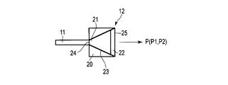
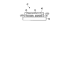
- FIG. 2 is a schematic configuration diagram of the wavelength conversion unit 12.
- the wavelength conversion unit 12 receives primary light emitted from the third optical fiber 11, that is, blue-violet laser light, blue laser light, or mixed excitation light, and first illumination light P according to these excitation lights. Alternatively, the second illumination lights P1 and P2 are irradiated. Specifically, the wavelength conversion unit 12 has low excitation intensity with respect to the blue-violet laser light ( ⁇ 1) as the primary light emitted from the third optical fiber 11, and does not emit fluorescence by wavelength conversion. ing.
- the wavelength conversion unit 12 transmits the blue-violet laser light ( ⁇ 1) and emits the blue-violet laser light ( ⁇ 1) as illumination light (observation light) P, here the first illumination light P1.
- the first illumination light P ⁇ b> 1 is composed of first primary light emitted from the first laser diode 5 as the first primary light source among the first or second laser diodes 5 and 6. Including at least one narrowband spectral element.
- the first illumination light P1 has a low intensity of a wavelength in which the absorption intensity of the substance of the subject Q is relatively difficult to absorb in the first color area of the color area including the first narrowband spectral element.
- the wavelength conversion unit 12 converts the wavelength of the blue laser light ( ⁇ 2) emitted from the third optical fiber 11 as the primary light, in this case, to yellow fluorescence ( ⁇ 3), and converts the fluorescence ( ⁇ 3) into Eject.
- the wavelength conversion unit 12 mixes the wavelength-converted fluorescence ( ⁇ 3) and a part of the blue laser light ( ⁇ 2) that is transmitted without being wavelength-converted by the wavelength conversion unit 12, and converts the mixed light into illumination light.
- (Observation light) P in this case, is emitted as second illumination light P2.
- the second illumination light P2 is excited by the second primary light emitted from the second laser diode 6 as the second primary light source among the primary light sources and the second primary light.
- generated by the 1st fluorescent substance (wavelength conversion member 22) is included.
- the structure of the wavelength conversion unit 12 includes a holder 20, a light transmission member 21, a wavelength conversion member 22, a reflection member 23, an incident part 24, and an emission part 25.
- the holder 20 holds the light transmission member 21 and the wavelength conversion member 22.
- the holder 20 is provided with a light transmission member 21 on the connection side of the third optical fiber 11, that is, on the primary light incident side.
- a wavelength conversion member 22 is provided on the emission side of the illumination light P of the holder 20.
- On the light transmitting member 21 side of the holder 20, an incident portion 24 for entering primary light is formed on the wavelength conversion member 22 side of the holder 20, an emission part 25 for emitting the illumination light P that is the first or second illumination light P1, P2 is formed.
- the inside of the holder 20 is formed in, for example, a conical tapered shape that is recessed in a concave shape.
- a film-like reflecting member 23 is formed on the tapered inner peripheral surface.
- the reflection member 23 regularly reflects or diffusely reflects laser light and fluorescence.
- the light transmission member 21 transmits primary light (blue-violet laser light, blue laser light, mixed light) emitted from the emission end of the third optical fiber 11 and fluorescence converted in wavelength by the wavelength conversion member 22. .
- the light transmitting member 21 is formed of a member such as glass or silicone resin having high transmittance.
- the wavelength converting member 22 absorbs primary blue laser light (center wavelength 445 nm: second excitation light: ⁇ 2) emitted from the second laser diode 6 and emits yellow fluorescence ( ⁇ 3).
- an oxide phosphor (YAG, TAG) having a Ce (cerium) activated garnet crystal structure is used as the wavelength conversion member 22.
- Oxide phosphors (YAG, TAG) are materials that can emit yellow fluorescence by absorbing blue laser light in a wavelength region of 430 nm to 470 nm.
- the oxide phosphor (YAG, TAG) can be used in combination with blue laser light having a peak in the wavelength region of 430 nm to 470 nm.
- the wavelength conversion member 22 has a low excitation intensity with respect to blue-violet laser light (center wavelength 415 nm: first excitation light: ⁇ 1) emitted from the first laser diode 5 and is not excited.
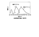
- FIG. 3 shows the excitation / fluorescence spectral characteristics of the oxide phosphor forming the wavelength conversion member 22.
- the excitation region of the excitation spectrum is defined as a region where the excitation intensity is half or more of the peak value.
- the visible light region is a wavelength region of 380 nm to 780 nm.
- the absorption region of the oxide phosphor in the visible light region in the wavelength region of 380 nm to 780 nm is approximately the wavelength region of 420 nm to 520 nm.
- the yellow fluorescence spectrum (first fluorescence) has a broad spectrum having a fluorescence peak at a central wavelength of 575 nm ( ⁇ 3) and a half width of 95 nm.
- the waveform of the fluorescence spectrum has a characteristic that the long wavelength side is gentler than the short wavelength side with respect to the fluorescence peak wavelength.
- the oxide phosphor is not excited because the excitation intensity is low with respect to blue-violet laser light (first excitation light) having a central wavelength of 415 nm ( ⁇ 1), which is the primary light emitted from the first laser diode 5. .
- the oxide phosphor has an excitation intensity of about 3 minutes with respect to the intensity of blue laser light (second excitation light) having a wavelength of 445 nm ( ⁇ 2), which is the primary light emitted from the second laser diode 6. If it is 1 or less, it can be regarded as not excited.
- the wavelength conversion member 22 is formed by dispersing a powdery phosphor in a sealing material such as silicone resin or glass and solidifying the sealing material.
- the thickness of the wavelength conversion member 22 and the concentration condition of the powdered phosphor mixed with the sealing material are determined from the third optical fiber 11 in consideration of the excitation light absorptivity and wavelength conversion efficiency characteristics of the phosphor.
- Blue laser light incident as light, that is, part of blue laser light (center wavelength 445 nm: second excitation light: ⁇ 2) emitted from the second laser diode 6 is a desired wavelength, here yellow fluorescence ( ⁇ 3) Set to convert to.
- the wavelength conversion member 22 is a blue-violet laser light (first excitation light) or blue laser light (second excitation light) that is incident from the third optical fiber 11 connected to the incident portion 24 of the holder 20. ) On the optical path axis.
- the wavelength conversion member 22 is formed in a cylindrical shape, for example.
- the wavelength conversion member 22 is installed in the vicinity of the optical axes of the first and second excitation lights from the third fiber 11.
- the system control unit 4 is connected to an input unit (mode instruction unit) 13.
- the input unit 13 sends, to the system control unit 4, observation mode information M indicating whether observation is performed in, for example, one of a normal light observation mode and a special light observation mode as a plurality of observation modes.
- the input unit 13 inputs, for example, observation mode information M in response to a manual operation by an operator or the like, or inputs observation mode information M from an external computer.
- the image acquisition device 3 separates the image of the irradiation region S of the subject Q, which is the observation target irradiated with the illumination light P by the light source device 2, into a plurality of color regions, and acquires an image.
- the image acquisition device 3 captures reflected light from the subject Q and acquires an image of the subject Q, for example, a normal light observation image in the normal light observation mode or a special light observation image in the special light observation mode.
- the image acquisition device 3 includes an imaging unit 30, an image processing unit 31, and an image display unit 35.
- the imaging unit 30 is controlled by an imaging control signal PC output from the system control unit 4.
- the imaging unit 30 captures the reflected light F from the irradiation region S of the subject Q of the illumination light P emitted from the light source device 2 and outputs a pixel signal for each BGR pixel.
- the imaging unit 30 is configured by an imaging device such as a CCD imager or a CMOS imager using an imaging element such as a CCD.
- FIG. 4 shows sensitivity wavelength characteristics of a general CCD imager.
- the CCD imager has a B pixel having a sensitivity peak at a wavelength of 460 nm ( ⁇ b) in the blue region, a G pixel having a sensitivity peak at a wavelength of 540 nm ( ⁇ g) in the green region, and a wavelength of 630 nm ( ⁇ r) in the red region.
- R pixels having a sensitivity peak are included.
- the sensitivity region of the B pixel exists up to a wavelength of 540 nm on the long wavelength side.
- the sensitivity region of the R pixel exists up to a wavelength of 540 nm on the short wavelength side.
- the B pixel and the G pixel, and the G pixel and the R pixel include a wavelength region in which the sensitivity overlaps in the adjacent wavelength region.
- the light reception sensitivity characteristic of the B pixel with respect to the wavelength ⁇ is defined as b ( ⁇ )
- the light reception sensitivity characteristic of the G pixel is defined as g ( ⁇ )
- the light reception sensitivity characteristic of the R pixel is defined as r ( ⁇ ).
- the image processing unit 31 performs image processing on each pixel signal output from the imaging unit 30 for each of the B pixel, the G pixel, and the R pixel, and acquires a normal light observation image and a special light observation image of the subject Q.
- the image processing unit 31 includes a first frame memory 32, a second frame memory 33, and a calculator 34.
- the image acquisition unit 31 acquires a special light observation image based on the plurality of illumination lights output from the light source device 2 and the wavelength characteristics of the color region included in the image acquisition unit 31. To do.
- the special light observation image includes, for example, narrow band spectral element information by overlapping the wavelength characteristics of the first and second illumination lights P1 and P2 as the plurality of illumination lights and the wavelength characteristics of the color region of the image acquisition unit 31. Is generated by combining the information of the narrowband spectral elements with a plurality of reflection images acquired for each irradiation of the first and second illumination lights P1 and P2.
- the image acquisition unit 31 acquires information on the first narrowband spectral element from the reflected image of each first imaging frame acquired every time the subject Q is irradiated with the first illumination light P1 from the light source device 2.
- the second narrowband spectral element information is obtained from the reflected image of each second imaging frame obtained each time the subject Q is irradiated with the second illumination light P2 from the light source device 2,
- the special light observation image is constructed by combining the information of the first narrowband spectral element and the information of the second narrowband spectral element.
- the first narrowband spectral element and the second narrowband spectral element each include a wavelength having a high absorption intensity of the subject Q and belong to different absorption peaks.
- the first and second frame memories 32 and 33 sequentially capture each pixel signal for each of the B pixel, G pixel, and R pixel output from the imaging unit 30, and store them as a reflected light image for each frame. Storage of the reflected light image for each frame in the first and second frame memories 32 and 33 is controlled by a storage frame signal FM output from the system control unit 4.
- the computing unit 34 reads each reflected light image stored in each of the first frame memory 32 and the second frame memory 33, performs an operation on each reflected light image, and displays the image on the image display unit 35.
- Information for example, a normal light observation image or a special light observation image is generated.
- the image display unit 35 displays the normal light observation image and the special light observation image acquired by the image processing of the image processing unit 31.
- the image display unit 35 includes, for example, a CRT or a liquid crystal display.
- the system control unit 4 sends a light source control signal LC to the light source control unit 7 according to the contents of the observation mode information M.
- the imaging control signal PC is sent to the imaging unit 30 and the storage frame signal FM is sent to the image processing device 31.
- the system control unit 4 sends a light source control signal LC to the light source control unit 7 so as to turn on the second laser diode 6.
- the system control unit 4 sends to the imaging unit 30 an imaging control signal PC for repeating the exposure processing in the imaging unit 30 and the transmission of each pixel signal for each BGR pixel obtained by the exposure processing.
- the system control unit 4 sends to the image processing device 31 a storage frame signal FM indicating a storage destination for storing the reflected light image for each frame obtained by imaging by the imaging unit 30 in the second frame memory 33.
- the image processing unit 31 displays the reflected light image for each frame obtained by the imaging of the imaging unit 30 when the second laser diode 6 is turned on, in the second frame memory 33. Save to.
- the computing unit 34 reads the reflected light image stored in the second frame memory 33, calculates the reflected light image, and generates a normal light observation image of the subject Q when the subject Q is irradiated with white light. Then, the normal light observation image is displayed on the image display unit 35.
- the system control unit 4 sequentially turns on a plurality of primary light sources in the light source device 2, that is, the first and second laser diodes 5 and 6, thereby primary light having a plurality of wavelengths. Are sequentially irradiated onto the subject Q, which is the observation target.
- the system control unit 4 sends a light source control signal LC to the light source control unit 7 so that the first and second laser diodes 5 and 6 are alternately turned on.
- the system control unit 4 sends to the imaging unit 30 an imaging control signal PC for repeating the exposure process and the transmission of each pixel signal for each BGR pixel to the imaging unit 30 as described above.
- the system control unit 4 generates an image of a storage frame signal FM indicating a storage destination for alternately storing the reflected light image for each frame obtained by the imaging of the imaging unit 30 in the first and second frame memories 32 and 33. It is sent to the processing device 31.
- the image processing unit 31 turns on the first and second laser diodes 4 and 5 alternately.
- the reflected light image obtained by the image pickup of the image pickup unit 30 is stored in the first and second frame memories 32 and 33 alternately and sequentially alternately for each frame.
- the reflected light image is stored as information including information of the first narrowband spectral element.
- the reflected light image is stored as information including information on the second narrowband spectral element.
- the calculator 34 reads the reflected light images stored in both the first and second frame memories 32 and 33, calculates each reflected light image to generate a special light observation image, and the special light observation image. Is displayed on the image display unit 35.
- the reflected light image obtained by imaging by the imaging unit 30 is alternately and sequentially stored in the first frame memory 32 and the second frame memory 33 for each frame.
- the imaging unit 30 causes the first frame memory 32 to be in the period of the exposure process performed immediately before.
- a reflected light image to be stored is generated.
- the reflected light image is stored in the first frame memory 32.
- the imaging unit 30 when the storage frame signal FM indicates the second frame memory 33 as a storage destination, the imaging unit 30 generates a reflected light image to be stored in the second frame memory 33 during the exposure process performed immediately before. Is done. Immediately after the exposure processing, the reflected light image is stored in the second frame memory 33.
- the image processing unit 31 stores the reflected light image for each frame in the first frame memory 32 or the second frame memory 33 according to the storage frame signal FM transmitted from the system control unit 4 as described above.
- the image processing unit 31 is not limited to this, and the observation mode information M indicating the normal light observation mode or the special light observation mode from the input unit 13 is directly input, and the reflected light image is input to the first frame memory 32 or the second frame. You may make it preserve
- FIG. For example, when the observation mode information M indicating the normal light observation mode is input, the image processing unit 31 displays a reflected light image for each frame obtained by imaging of the imaging unit 30 when the second laser diode 6 is turned on. Saved in the second frame memory 33.
- the image processing unit 31 reflects the reflected light obtained by imaging of the imaging unit 30 when the first and second laser diodes 4 and 5 are alternately lit.
- the image is repeatedly and alternately stored in the first frame memory 32 and the second frame memory 33 for each frame.
- the storage location of the reflected light image is determined by the image processing unit 31 as to whether the exposure process has been performed during the period when either the first or second laser diode 4 or 5 is lit, and according to the determination result. In this case, it is only necessary to determine whether to store in the first or second frame memory 32, 33.
- the image processing unit 31 acquires a plurality of reflected light images each time a plurality of illumination lights are irradiated onto the subject Q that is an observation target, and the first frame memory 32 and the second frame image for each frame.
- the frame memory 33 is alternately and repeatedly stored, and a special light observation image of the subject Q is generated based on each reflected light image.
- the image processing unit 31 has a white balance coefficient that determines color information when generating an image in the normal light observation mode and when generating an image in the special light observation mode.
- the white balance coefficient is, for example, a light emission intensity characteristic P ( ⁇ ) with respect to the wavelength ⁇ of the illumination light P and a light receiving sensitivity characteristic b ( ⁇ ), g ( ⁇ ), r ( ⁇ ) of the CCD as the image pickup device of the image pickup unit 30
- the reflection characteristic is set using a white plate that is substantially flat in the visible light region.
- the color components B, G, and R obtained by multiplying the emission intensity characteristic P ( ⁇ ) of the illumination light P and the light receiving sensitivity characteristics b ( ⁇ ), g ( ⁇ ), and r ( ⁇ ) of the CCD are as follows. Calculated.
- the white balance coefficient Wb of the color component B with respect to the color component G is B / G
- the white of the color component R with respect to the color component G The balance coefficient Wr is R / G.
- the white balance coefficients Wb and Wr are, for example, 1 A range of / 3 to 3 is preferable.
- the ratio of the color component in the illumination light P the light quantity of R color having a wavelength of 600 nm or more at which the R pixel has the maximum sensitivity is compared with the wavelength range in which the G pixel has the maximum sensitivity, for example, the light quantity of 525 nm to 555 nm. It is preferable that there is 1/3 or more.
- the light source control unit 7 receives the light source control signal LC output from the system control unit 4 and controls the lighting of the first or second laser diode 5 or 6 according to the light source control signal LC. For example, in the normal light observation mode, the system control unit 4 sends a light source control signal LC for turning on the second laser diode 6, so that the light source control unit 7 drives the second laser diode 6 to turn on. . On the other hand, in the special light observation mode, the system control unit 4 sends the light source control signal LC so as to turn on the first and second laser diodes 5 and 6 alternately. The first and second laser diodes 5 and 6 are driven to turn on alternately.
- the light source controller 7 controls the drive currents and drive methods of the first and second laser diodes 5 and 6, for example, pulse drive, continuous drive (CW), and the like to control the first and second laser diodes 5. , 6 are lit.
- observation mode information M When an observation mode in the normal light observation mode is input to the input unit 13 from a manual operation such as an operator or an external computer, the input unit 13 sends observation mode information M indicating the normal light observation mode to the system control unit 4.
- the system control unit 4 sends a light source control signal LC for turning on the second laser diode 6 to the light source control unit 7.
- the system control unit 4 sends to the imaging unit 30 an imaging control signal PC for repeating the exposure process in the imaging unit 30 and the transmission of each pixel signal for each BGR pixel obtained by the exposure process.
- the system control unit 4 sends to the image processing device 31 a storage frame signal FM indicating a storage destination for storing the reflected light image for each frame obtained by imaging by the imaging unit 30 in the second frame memory 33.
- the light source control unit 7 When the light source control unit 7 inputs the light source control signal LC for lighting the second laser diode 6, the light source control unit 7 drives the second laser diode 6 to light according to the light source control signal LC.
- the second laser diode 6 emits primary light (first excitation light) that is blue laser light having a central wavelength of 445 nm ( ⁇ 2).
- the blue laser light is guided to the second optical fiber 10, the optical coupler 9, and the third optical fiber 11 and enters the wavelength conversion unit 12.
- the wavelength conversion unit 12 converts the wavelength of a part of the incident blue laser light into yellow fluorescence ( ⁇ 3) by the phosphor that is the wavelength conversion member 22. At the same time, the wavelength conversion unit 12 transmits blue laser light that is not absorbed by the phosphor and is not wavelength-converted to yellow fluorescence. Thereby, the wavelength conversion unit 12 emits the yellow fluorescent light and the blue laser light whose wavelengths have been converted from the emission end as illumination light P (second illumination light P2).
- the second illumination light P2 is applied to the subject Q, and an irradiation region S is formed on the subject Q.
- the second illumination light P2 emitted from the wavelength conversion unit 12 has a predetermined light distribution angle.
- the size of the irradiation region S of the second illumination light P2 irradiated on the subject Q is formed by the relationship between the light distribution angle and the distance between the emission end of the wavelength conversion unit 12 and the subject Q.
- the irradiation region S is a region having a size including at least the range imaged by the imaging unit 30, and is preferably wider than the imaging range of the imaging unit 30.
- the second illumination light P2 in the normal light observation mode is white light.
- a continuous flat spectral component from the green to the red wavelength region is effective.
- FIG. 5 shows the spectral characteristic P ( ⁇ ) of the second illumination light P2.
- a spectrum component in each color region of BGR is defined as a region where a light intensity greater than, for example, 1/20 of the maximum light intensity in each color region of BGR exists. On the other hand, it is assumed that the light intensity that is 1/20 or less of the maximum light intensity has no spectral component.
- the second illumination light P2 emitted from the wavelength conversion unit 12 is a mixture of a narrow-band blue laser beam having a peak at a central wavelength of 445 nm ( ⁇ 1) and yellow fluorescence having a peak near the central wavelength of 565 nm ( ⁇ 3).
- the mixed light is set to a component ratio of blue laser light and yellow fluorescence that is in the vicinity of white light.
- the maximum intensity in the wavelength region of 450 nm to 480 nm between the blue laser light and the yellow fluorescence is less than 1/20 of the intensity of the peak wavelength ( ⁇ 1) of the blue laser light. .
- the amount of light in the wavelength region 450 nm to 480 nm is one-twentieth or less of the amount of light in the wavelength region 400 nm to 440 nm.
- the ratio of the amount of light in the blue region, green region, and red region of the second illumination light P2 is approximately 5 (blue): 3 (green): 2 (red).
- the difference between the wavelength ⁇ 2 (blue laser light) and the wavelength ⁇ 3 (yellow fluorescence) is approximately 150 nm.
- the wavelength difference between the full width at half maximum of blue laser light and the full width at half maximum of yellow fluorescence is approximately 80 nm.
- the imaging unit 30 captures the reflected light F from the irradiation region S of the subject Q irradiated with the second illumination light P2, and outputs a pixel signal for each BGR pixel.
- the image processing unit 31 sets a storage destination for storing the reflected light image for each frame output from the system control unit 4 in the second frame memory 33.
- each pixel signal of BGR acquired by imaging of the imaging unit 30 is input, a reflected light image is generated for each frame based on each pixel signal level of BGR, and the reflected light for each frame The image is stored in the second frame memory 33.
- the calculator 34 of the image processing unit 31 calculates a reflected light image stored in the second frame memory 33 to generate a normal light observation image of the subject Q when the subject Q is irradiated with white light,
- the normal light observation image is displayed on an image display unit 35 such as a CRT or a liquid crystal display.
- the computing unit 34 performs predetermined image processing, such as white balance, noise reduction, structure enhancement, and gamma correction, on the received light signals of the respective BGR pixels stored in the second frame memory 33. Processing is performed to generate a normal light observation image.
- the normal light observation image is generated using all spectral components included in the second illumination light P2.
- the input unit 13 sends observation mode information M indicating the special light observation mode to the system control unit 4.
- the system control unit 4 sends a light source control signal LC to the light source control unit 7 so that the first and second laser diodes 5 and 6 are alternately turned on.
- the light source control signal LC includes information for distinguishing whether the first or second laser diode 5 or 6 is turned on.
- the system control unit 4 alternately sends, for example, a light source control signal LC for lighting the first laser diode 5 and a light source control signal LC for lighting the second laser diode 6.
- the system control unit 4 sends to the imaging unit 30 an imaging control signal PC for repeating the exposure processing and the transmission of each pixel signal for each BGR pixel to the imaging unit 30 as described above.
- the system control unit 4 generates an image of a storage frame signal FM indicating a storage destination for alternately storing the reflected light image for each frame obtained by the imaging of the imaging unit 30 in the first and second frame memories 32 and 33. It is sent to the processing device 31.
- the system control unit 4 alternately sends a light source control signal LC for turning on the first laser diode 5 and a light source control signal LC for turning on the second laser diode 6.
- a light source control signal LC for turning on the first laser diode 5 sent from the system control unit 4 and a light source control signal LC for turning on the second laser diode 6 are alternately input to the light source control unit 7.
- the first and second laser diodes 5 and 6 are driven to turn on and off alternately.
- the first laser diode 5 When the first laser diode 5 is turned on, the first laser diode 5 emits a blue-violet laser beam in a narrow band with a center wavelength of 415 nm ( ⁇ 1) as a light emission peak and a half-value width of several nm or less as primary light. Inject as.
- the blue-violet laser light is guided to the second optical fiber 10, the optical coupler 9, and the third optical fiber 11 and enters the wavelength conversion unit 12.
- the wavelength conversion member 22 has a low excitation intensity with respect to the blue-violet laser light (center wavelength 415 nm: ⁇ 1) emitted from the first laser diode 5 and is not excited. Therefore, the wavelength conversion unit 12 transmits the blue-violet laser beam ( ⁇ 1) and emits the blue-violet laser beam ( ⁇ 1) as illumination light P (first illumination light P1).
- FIG. 6 shows the spectral characteristic P ( ⁇ 1) of the first illumination light P1.
- the light intensity of the yellow fluorescent light emitted when the wavelength conversion member 22 is irradiated with the first illumination light P1 is 1/20 of the maximum light intensity of the blue-violet laser light (center wavelength 415 nm: ⁇ 1). It is as follows. As described above, the wavelength conversion member 22 has a low excitation intensity with respect to the blue-violet laser light emitted from the first laser diode 5 and is not excited.
- the imaging unit 30 captures the reflected light F from the irradiation region S of the subject Q irradiated with the first illumination light P1, and outputs a pixel signal for each BGR pixel.
- the image processing unit 31 outputs the reflected light image for each frame output from the system control unit 4 at the lighting timing.
- Each BGR pixel signal acquired by imaging by the imaging unit 30 is input in accordance with a storage frame signal FM indicating a storage destination for storage in the frame memory 32.
- the image processing unit 31 generates a reflected light image of one frame based on each BGR pixel signal level, and stores the reflected light image of the frame in the first frame memory 32.
- the second laser diode 6 when the second laser diode 6 is turned on, the second laser diode 6 emits blue laser light having a center wavelength of 445 nm ( ⁇ 2) as described above.
- the blue laser light is guided to the second optical fiber 10, the optical coupler 9, and the third optical fiber 11 and enters the wavelength conversion unit 12.
- the wavelength conversion unit 12 wavelength-converts a part of the incident blue laser light into yellow fluorescence ( ⁇ 3) by the phosphor that is the wavelength conversion member 22.
- the wavelength conversion unit 12 transmits blue laser light that is not absorbed by the phosphor and is not wavelength-converted to yellow fluorescence. Thereby, the wavelength conversion unit 12 emits yellow fluorescent light and blue laser light as the second illumination light P2.
- the second illumination light P2 is applied to the subject Q, and an irradiation region S is formed on the subject Q.
- the imaging unit 30 captures the reflected light F from the irradiation region S of the subject Q irradiated with the second illumination light P2, and outputs a pixel signal for each BGR pixel.
- the image processing unit 31 When the second laser diode 6 is turned on in the special light observation mode, the image processing unit 31 outputs the reflected light image for each frame output from the system control unit 4 at the lighting timing.
- Each BGR pixel signal acquired by imaging by the imaging unit 30 is input in accordance with a storage frame signal FM indicating a storage destination for storage in the frame memory 33.
- the image processing unit 31 generates a reflected light image for each frame based on each BGR pixel signal level, and stores the reflected light image in the second frame memory 33 for each frame.
- the first and second laser diodes 4 and 5 are alternately and repeatedly turned on. Therefore, when the first laser diode 5 is turned on, the reflected light image of the subject Q is It is stored in the first frame memory 32.
- the second laser diode 6 is turned on, the reflected light image of the subject Q is stored in the second frame memory 33. That is, when the first laser diode 5 is turned on, the reflected light image generated during the exposure period of the imaging unit 30 at the lighting timing is stored in the first frame memory 32.
- the second laser diode 6 is turned on, the reflected light image generated during the exposure period of the imaging unit 30 at the lighting timing is stored in the second frame memory 33.
- FIG. 7 shows an absorption coefficient serving as an index of the absorption intensity of hemoglobin flowing into the blood vessel K in the living tissue.
- hemoglobin In the visible light region in the wavelength region of 380 nm to 780 nm, hemoglobin has absorption intensity peaks at different wavelengths near the wavelength 415 nm ( ⁇ h1) and near the wavelength 540 nm ( ⁇ h2). It has the property that the absorption intensity near the wavelength of 415 nm ( ⁇ h1) is the largest.
- NBI observation which is special light observation for an endoscope or the like, is light having two wavelengths including a wavelength region of about 415 nm ( ⁇ h1) and a wavelength of about 540 nm ( ⁇ h2), for example, a wavelength region of about 400 nm to 440 nm.
- Light and light having a wavelength region of approximately 525 nm to 555 nm are used as illumination light P (observation light).
- NBI observation is based on observing the blood vessel K and the like with good contrast by utilizing the depth of light that the light of the wavelength penetrates from the surface of the living tissue and the scattering characteristics of the light of each wavelength. This is a technique (special light observation) that facilitates the discovery of cancer and the like.
- the first illumination light P1 in the present embodiment uses blue-violet laser light having a center wavelength of 415 nm ( ⁇ 1) as primary light, and this blue-violet laser light is absorbed and scattered by a relatively surface layer portion of a living tissue. This is effective for observing a blood vessel K in the vicinity of the surface of the living tissue as the specimen Q.
- the second illumination light P2 includes a component that becomes white light by blue laser light having a central wavelength of 445 nm ( ⁇ 2) and yellow fluorescence ( ⁇ 3) having a peak near the wavelength of 565 nm. Yellow fluorescence has a broad spectrum and includes light having a wavelength near 540 nm.
- the peak wavelength ⁇ 3 of the yellow fluorescent component is present in the wavelength band of the absorption coefficient which is equal to or greater than half the absorption coefficient of the absorption peak wavelength of 540 nm of hemoglobin in the green region. Since the rate of absorption by observation of the blood vessel K increases and the sensitivity of the G pixel increases, an image with high contrast can be obtained.
- the absorption characteristics of hemoglobin show a tendency that the absorption intensity decreases rapidly as it goes from the wavelength near 415 nm ( ⁇ h1) to the longer wavelength side.
- the absorption intensity decreases to approximately 1/5 at a wavelength difference of 35 nm.
- the living tissue in the subject Q often shows red from skin color.
- the absorption characteristics of the living tissue in the subject Q gradually decrease in the absorption coefficient from the blue region to the red region, and the absorption of hemoglobin near the wavelength 415 nm ( ⁇ h1) of the blue region.
- the blue laser light having a central wavelength of 445 nm ( ⁇ 2) included in the second illumination light P2 as the observation light has a light amount of the blue region in which hemoglobin is absorbed by the living tissue. It is necessary to increase the proportion.
- the first light quantity in the vicinity of a wavelength of 415 nm ( ⁇ h1) where the absorption coefficient of hemoglobin is larger than the absorption coefficient of the living tissue is used, and the first light quantity near the wavelength of 450 nm where the absorption coefficient of hemoglobin is smaller than the absorption coefficient of the living tissue.
- the amount of light should be greater than 2.
- the B pixel of the CCD of the imaging unit 30 used for image acquisition is approximately twice as high in sensitivity near the wavelength 450 nm as near the wavelength 415 nm ( ⁇ 1) where the absorption coefficient of hemoglobin is larger than the absorption coefficient of living tissue. . Therefore, if the light amount in the wavelength region 450 nm to 480 nm, which is the blue region from the wavelength 450 nm to the long wavelength side, is about a half of the light amount in the wavelength region 400 nm to 440 nm in the vicinity of the wavelength 415 nm, as described above, B The sensitivity of the pixel is about twice as high.
- the amount of light in the wavelength region 450 nm to 480 nm is larger than the amount of light in the wavelength 415 nm ( ⁇ 1).
- the amount of light in the wavelength region of 450 nm to 480 nm affects image noise when increasing the contrast. That is, when observing a blood vessel K (having hemoglobin flowing) in the vicinity of the surface of the subject Q, it is affected by image noise generated by absorption by a living tissue.
- the light amount in the wavelength region of 450 nm to 480 nm is set to 1/10 or less of the light amount in the wavelength region 400 nm to 440 nm, an image with high contrast can be obtained in addition to image noise reduction.
- the first illumination light P1 and the second illumination light P2 are respectively in the irradiation region S on the subject Q.
- a part is absorbed by the absorption characteristics of a certain blood vessel K or living tissue, and the remaining part is scattered and reflected, and received by the B pixel, G pixel, and R pixel of the imaging unit 30.
- the light receiving sensitivity characteristic of the B pixel exists in the wavelength region of 380 nm to 540 nm.
- the reflected light F received by the B pixel when irradiated with the second illumination light P2 corresponds to a short wavelength region portion of blue laser light ( ⁇ 2) and yellow fluorescence ( ⁇ 3) as the second primary light.
- the component received by the B pixel is mainly blue laser light.
- the blue laser light ( ⁇ 2) which is the primary light included in the second illumination light P2, causes image noise in the special light observation.
- the reflected light F received by the B pixel when irradiated with the first illumination light P1 is blue-violet laser light ( ⁇ 1) which is primary light.
- the component received by the B pixel is blue-violet laser light.
- the blue-violet laser beam ( ⁇ 1) has an intensity near the wavelength 415 nm ( ⁇ h1), which is the first absorption peak of hemoglobin, and is absorbed and scattered at a relatively surface layer portion of the living tissue.
- the reflected light image for each frame acquired by irradiating the first illumination light P1 and stored in the first frame memory 32 relates to the state of the blood vessel K near the surface of the tissue as B pixel information. Information is stored.
- the primary light that is, the blue laser light ( ⁇ 2) included in the second illumination light P2 is reflected as B pixel information.
- the information of the light F is not included, and the influence of noise generated by absorption of blue laser light by a living tissue other than hemoglobin can be reduced.
- FIG. 8 shows a portion M corresponding to the second narrowband spectral element in which the light receiving sensitivity characteristic of the G pixel and the wavelength spectrum of yellow fluorescence ( ⁇ 3) overlap.
- the light receiving sensitivity characteristic of the G pixel exists in the wavelength region of 460 nm to 640 nm.
- the reflected light F received by the G pixel when irradiated with the second illumination light P2 corresponds to a wavelength region near the intensity peak of yellow fluorescence ( ⁇ 3).
- a portion M where the light receiving sensitivity characteristic of the G pixel and the wavelength spectrum of yellow fluorescence ( ⁇ 3) overlap is taken into the G pixel.
- the short wavelength end of the intensity spectrum of yellow fluorescence ( ⁇ 3) having a peak near the wavelength of 565 nm is sandwiched between the light receiving sensitivity characteristics of the G pixel.
- a portion M where the light receiving sensitivity characteristic of the G pixel and the wavelength spectrum of yellow fluorescence ( ⁇ 3) overlap each other has a narrower characteristic than the wavelength spectrum of each, and corresponds to a second narrowband spectral element.
- the portion M of the second narrowband spectral element has an intensity near a wavelength of 540 nm ( ⁇ h2), which is the second absorption peak of hemoglobin.
- the portion M of the second narrowband spectral element is under the skin, while the light of the wavelength is scattered to some extent when irradiated on the living tissue as described above, but proceeds deeper than the light of the wavelength of 415 nm ( ⁇ h1). Since it is absorbed and scattered by the blood vessel K and the like, it is effective for observing the blood vessel K in the subcutaneous tissue.
- the G pixel does not receive the reflected light F because it has no intensity in the wavelength region having the light receiving sensitivity of the G pixel.
- the long wavelength boundary value of the G pixel exists between the short wavelength boundary value and the long wavelength boundary value of the yellow fluorescence ( ⁇ 3), and the short wavelength boundary value of the G pixel is shorter than the short wavelength boundary value of the yellow fluorescence ( ⁇ 3). It exists in the wavelength. Not limited to this, the short wavelength boundary value of the G pixel exists between the short wavelength boundary value and the long wavelength boundary value of the yellow fluorescence ( ⁇ 3), and the long wavelength boundary value of the G pixel is greater than the long wavelength boundary value of the yellow fluorescence. May also exist at longer wavelengths.
- the light receiving sensitivity characteristic of the R pixel exists in the wavelength region of 540 nm to 720 nm.
- the long wavelength region of the yellow fluorescence ( ⁇ 3) of the second illumination light P2 also includes a red region component having a wavelength of 580 nm or more. Accordingly, the R pixel mainly receives the red region component of the second illumination light P2.
- the R pixel irradiates the first illumination light P1
- the R pixel does not receive the reflected light F because it does not have the light receiving sensitivity with respect to the wavelength region included in the first illumination light P1.
- Each pixel signal of BGR received by the CCD of the imaging unit 30 is transmitted to the image processing unit 31.
- the image processing unit 31 responds each time the subject Q is irradiated with the first illumination light P1 according to the storage frame signal FM output from the system control unit 4.
- a reflected light image is generated for each frame to be stored in the first frame memory 32, and a reflected light image is generated for each corresponding frame every time the subject Q is irradiated with the second illumination light P2.
- the storage frame signal FM indicates a storage destination for sequentially storing the reflected light image for each frame in the first and second frame memories 32 and 33 alternately.
- the first and second illumination lights P1 and P2 are alternately turned on sequentially.
- the image processing unit 31 outputs a pixel signal output from the B pixel of the imaging unit 30 every time the subject Q is irradiated with the first illumination light P1 of the blue-violet laser light ( ⁇ 1). Is stored in the first frame memory 32.
- the image processing unit 31 outputs a pixel signal output from the G pixel of the imaging unit 30 to the second frame memory 33 every time the subject Q is irradiated with the second illumination light P2 of the narrow-band blue laser light ( ⁇ 2). Save to.
- the image processing unit 31 reads the pixel signal of the B pixel stored in the first frame memory 32 and also reads the pixel signal of the G pixel stored in the second frame memory 33, and the pixel signal of the B pixel and the G signal
- the pixel signal of the pixel is sent to the calculator 34.
- the computing unit 34 assigns the pixel signal of the B pixel read from the first frame memory 32 to the B pixel and the G pixel of the image information for sending to the image display unit 35, and reads out from the second frame memory 33.
- the pixel signal of the G pixel is assigned to the R pixel of the image information for sending to the image display unit 35, and a special light observation image is generated based on predetermined image processing.
- the special light observation image is generated using a blue region included in the first illumination light P1 and a green region included in the second illumination light P2 among the components included in the illumination light P.
- the calculator 34 sends the generated special light observation image to the image display unit 35.
- the image display unit 35 displays the special light observation image on, for example, a CRT or a liquid crystal display.
- the second laser diode 6 in the normal light observation mode, when the second laser diode 6 is turned on, the reflected light image for each frame obtained by imaging by the imaging unit 30 is displayed.
- the image is stored in the second frame memory 33, and the stored reflected light image is calculated to generate a normal light observation image of the subject Q when the subject Q is irradiated with white light.
- the special light observation mode the first and second laser diodes 5 and 6 are alternately turned on, and the reflected light images for each frame obtained by the imaging of the imaging unit 30 are displayed as the first and second reflected light images.
- the images are alternately stored in the frame memories 32 and 33, the reflected light images stored in both the first and second frame memories 32 and 33 are read out, and each reflected light image is calculated to generate a special light observation image.
- the normal light observation mode is input as the observation mode information M
- the special light observation mode is input as the observation mode, it is possible to acquire the special light observation image in which the subject Q is irradiated with the two illumination lights P1 and P2 and the contrast of the blood vessel K is highlighted.
- the second illumination light P2 has a component that becomes white light by blue laser light having a central wavelength of 445 nm ( ⁇ 2) and yellow fluorescence having a peak in the vicinity of wavelength 565 nm ( ⁇ 3).
- yellow fluorescence includes light having a wavelength of around 540 nm.
- the light in the vicinity of the wavelength of 540 nm is scattered to some extent at the time of irradiation of the living tissue, but travels deeper into the living tissue than the blue-violet laser beam with a wavelength of 415 nm ( ⁇ 1), and is absorbed by the blood vessel K or the like under the skin. Since it is scattered, it is effective for observing blood vessels K in the subcutaneous tissue.
- the peak wavelength ⁇ 3 of the yellow fluorescent component is present in the wavelength band of the absorption coefficient which is equal to or greater than half the absorption coefficient of the absorption peak wavelength of 540 nm of hemoglobin in the green region. Since the rate of absorption by observation of the blood vessel K increases and the sensitivity of the G pixel increases, an image with high contrast can be obtained.
- the second illumination light P2 is white light including blue laser light having a central wavelength of 445 nm ( ⁇ 2) and yellow fluorescence having a peak near the wavelength of 565 nm ( ⁇ 3).
- the spectral component of the second illumination light P2 includes blue laser light having a wavelength of 420 nm near the absorption peak of hemoglobin and an absorption peak of 540 nm of hemoglobin in the green region.
- the second illumination light P2 white light including red light is realized, so that normal light observation can be realized in combination with the predetermined image acquisition device 3. Since the first illumination light P1 emitted in the normal light observation mode and the second illumination light P2 emitted in the special light observation mode are emitted from the same wavelength conversion unit 12, a reduction in size can be realized. In the case where there is a limit to the region where the light source such as the first and second laser diodes 5 and 6 and the wavelength conversion unit 12 are disposed, it is particularly effective for a nasal endoscope, for example.
- the image acquisition in the special light observation mode is configured to acquire two image frames. However, only the B pixel information of the first frame image stored in the first frame memory 32 or the second frame memory 33 is stored.
- the special light image may be configured from only one of the G pixel information of the second frame image to be stored.
- the second laser diode 6 is not turned on to emit blue-violet laser light as primary light, but the first laser diode 5 is also turned on to emit blue laser light as primary light. May be injected as In this case, since the shape of the spectrum of the second illumination light P2 changes, it is possible to adjust the color by adjusting the intensity of the blue laser light emitted from the first laser diode 5.
- the first illumination light P1 and the second illumination light P2 are always switched and irradiated, and the reflected light images for each frame obtained by the imaging of the imaging unit 30 are displayed as the first and second illumination lights.
- the frame memories 32 and 33 may be sequentially stored.
- the computing unit 34 constructs a normal light observation image from the reflected light image stored in the second frame memory 33 according to the observation mode information M, or the first frame memory 32 and the first frame memory 32.
- a configuration may be adopted in which the operation of constructing a special light observation image by combining the reflected light images stored in the second frame memory 33 is switched.
- hemoglobin is used as the target substance, but another substance existing in the body may be used, or a fluorescent probe administered from outside the body may be used.
- the absorption wavelength region of the fluorescent probe is preferably matched with the wavelength of the excitation light.
- a fluorescent probe is administered from outside the subject and emits light in response to a specific wavelength.
- the blue laser emitted from the semiconductor laser one having a peak wavelength in a wavelength region of 400 nm to 440 nm where the absorption coefficient of hemoglobin is large can be used.
- the peak wavelength of the blue laser light exists between the absorption peak wavelengths of 415 nm and 440 nm of the hemoglobin. This is more preferable because it is high and a bright image can be easily obtained.
- the wavelength conversion member 22 is not limited to an oxide phosphor (YAG, TAG) having a Ce (cerium) activated garnet crystal structure, but may be a phosphor that absorbs light in the blue band and emits yellow broad fluorescence.
- YAG, TAG oxide phosphor
- Ce cerium
- Eu-activated oxynitride phosphors and Eu-activated sulfide phosphors can be used.
- the blue light component received by the G pixel is small. Less effect as special light image noise. Desirably, it is 1/10 or less.
- FIG. 9 is a configuration diagram of the wavelength conversion unit 12 in the subject observation apparatus including the light source device.
- the wavelength conversion unit 12 has a two-color light configuration and includes two wavelength conversion members 22-1 and 22-2.
- One wavelength conversion member 22-1 absorbs blue laser light having a central wavelength of 445 nm ( ⁇ 2) emitted as the primary light from the second laser diode 6 and emits fluorescence in the green region.
- the wavelength conversion member 22-1 is made of, for example, a Ce-activated oxide phosphor.
- the wavelength conversion member 22-1 is not excited by the blue-violet laser light having a wavelength of 415 nm ( ⁇ 1) emitted as the primary light from the first laser diode 5.
- FIG. 10 shows the absorption / fluorescence characteristics of the wavelength converting member (green) 22-1.
- the other wavelength converting member 22-2 is blue violet laser light having a wavelength of 415 nm ( ⁇ 1) emitted from the first laser diode 5 or blue light having a central wavelength of 445 nm ( ⁇ 2) emitted from the second laser diode 6. Absorbs the primary light of the laser beam and emits fluorescence in the red region.
- the wavelength conversion member 22-2 is made of, for example, an Eu activated nitride phosphor.
- FIG. 11 shows the absorption / fluorescence characteristics of the wavelength converting member (red) 22-2.
- the other wavelength converting member 22-2 is a fluorescent material that absorbs green fluorescent light and does not absorb blue-violet laser light having a wavelength of 415 nm ( ⁇ 1) emitted from the first laser diode 5 as a fluorescent material. Material may be used.
- the wavelength conversion member 22-2 may be a fluorescent material that emits light by absorbing blue laser light having a central wavelength of 445 nm ( ⁇ 2) emitted from the second laser diode 6 as primary light.
- wavelength conversion unit 12 when the first laser diode 5 is turned on and a blue-violet laser beam having a wavelength of 415 nm ( ⁇ 1) is emitted from the first laser diode 5, one wavelength conversion member 22-1 is not excited by the blue-violet laser beam having the wavelength of 415 nm ( ⁇ 1) but transmits the blue-violet laser beam.
- the other wavelength conversion member 22-2 absorbs the primary light of the blue-violet laser beam having a wavelength of 415 nm ( ⁇ 1) emitted from the first laser diode 5 and emits fluorescence in the red region.
- the wavelength conversion unit 12 mixes the blue-violet laser light transmitted through the one wavelength conversion member 22-1 and the red region fluorescence emitted from the other wavelength conversion member 22-2 in a predetermined ratio.
- the white first illumination light P1 is emitted.
- one wavelength conversion member 22-1 becomes the second laser diode.
- the primary light of blue laser light having a central wavelength of 445 nm ( ⁇ 2) emitted from the diode 6 is absorbed to emit green region fluorescence.
- one wavelength conversion member 22-1 transmits part of the blue laser light having a central wavelength of 445 nm ( ⁇ 2) that does not contribute to the emission of fluorescence in the green region.
- the other wavelength conversion member 22-2 absorbs the primary light of the blue laser light having the central wavelength of 445 nm ( ⁇ 2) emitted from the second laser diode 6 and emits fluorescence in the red region.
- the wavelength conversion unit 12 includes a part of the blue laser light transmitted through the one wavelength conversion member 22-1, the green region fluorescence emitted from the wavelength conversion member 22-1, and the other wavelength conversion member 22.
- -2 emits the second illumination light P2 mixed with the fluorescence of the red region emitted by -2 at a predetermined ratio.
- the wavelength conversion unit 12 when the second laser diode 6 is turned on in the normal light observation mode, the wavelength conversion unit 12 includes a part of the blue laser light transmitted through one wavelength conversion member 22-1, The white second illumination light P2 in which the green region fluorescence emitted by the wavelength conversion member 22-1 and the red region fluorescence emitted by the other wavelength conversion member 22-2 are mixed at a predetermined ratio is emitted. .
- the second illumination light P2 is applied to the subject Q.
- the reflected light image for each frame obtained by imaging by the imaging unit 30 is stored in the second frame memory 33, the stored reflected light image is calculated, and the subject Q is irradiated with white light.
- a normal light observation image of the subject Q is generated.
- the wavelength conversion unit 12 has one wavelength conversion member 22-1.
- the first illuminating light P1 is emitted by mixing the blue-violet laser light transmitted through and the red region fluorescence emitted by the other wavelength conversion member 22-2 at a predetermined ratio.
- the wavelength conversion unit 12 transmits a part of the blue laser light transmitted through the one wavelength conversion member 22-1 and the fluorescence in the green region emitted by the wavelength conversion member 22-1. Then, the second illumination light P2 in which the red region fluorescence emitted from the other wavelength conversion member 22-2 is mixed at a predetermined ratio is emitted.
- the first illumination light P1 and the second illumination light P2 are alternately and sequentially irradiated onto the subject Q.
- the reflected light image for each frame obtained by imaging by the imaging unit 30 is alternately stored in the first and second frame memories 32 and 33.
- Each reflected light image stored in both the first and second frame memories 32 and 33 is read from each frame memory 32 and 33 and is calculated by the image processing unit 31 to generate a special light observation image. Is done.
- the wavelength conversion unit 12 absorbs the primary light of the blue laser light having the central wavelength of 445 nm ( ⁇ 2) emitted from the second laser diode 6 to absorb the green region.
- One wavelength conversion member 22-1 that emits fluorescence and is not excited by the primary light of blue-violet laser light having a wavelength of 415 nm ( ⁇ 1) emitted from the first laser diode 5 and the first laser diode 5 Absorbs the primary light of the emitted blue violet laser light having a wavelength of 415 nm ( ⁇ 1) or the blue laser light having a central wavelength of 445 nm ( ⁇ 2) emitted from the second laser diode 6 to emit red region fluorescence.
- the other wavelength conversion member 22-2 was formed.
- the second illumination light P2 includes part of the blue laser light transmitted through one wavelength conversion member 22-1 and the wavelength conversion member 22-1.
- the color rendering in the normal light observation mode is improved.
- the second embodiment reproduces red tissue that is present in a large amount of living tissue in the subject Q because the spectral components in the red region are present up to the longer wavelength side. It can be realized that it can be observed with high performance.
- the wavelength conversion unit 12 is not limited to laminating the wavelength conversion members 22-1 and 22-2 in this order with respect to the incident direction of the primary light of the blue laser beam and the blue-violet laser beam, but also the wavelength conversion member 22-2. , 22-1 may be laminated in this order.
- FIG. 12 shows a configuration diagram of the light source device 41.
- the light source device 2 replaces the first and second laser diodes 5 and 6 in the respective embodiments with the first and second light emitting diodes LED1 and 2, respectively, and converts the wavelength conversion member 22 into the wavelength converter 40. Instead, the light source device 31 was integrated.
- the light source device 41 is provided with a substrate 42. On the board
- the first light emitting diode LED1 corresponds to the first laser diode 5.
- the first light emitting diode LED1 emits, for example, blue-violet LED light (first excitation light) of primary light in the wavelength region of the first spectrum.
- the second light emitting diode LED2 corresponds to the second laser diode 6.
- the second light emitting diode LED2 emits blue LED light (second excitation light) of primary light in the wavelength region of the second spectrum.
- a wavelength converter 40 is provided so as to cover the first and second light emitting diodes LED1,2.
- a first resin 43 is filled between the wavelength converter 40 and each of the light emitting diodes LEDs 1 and 2.
- the first resin 43 is formed of a light transmissive resin for guiding each LED light emitted from the first and second light emitting diodes LED 1 and 2 to the wavelength converter 40.
- the wavelength converter 40 receives each LED light emitted from each light emitting diode LED1, 2 and emits the first or second illumination light P1, P2.
- the wavelength converter 40 includes a second resin 44 and a plurality of phosphors 45 scattered in the second resin 44.
- Each phosphor 45 is a primary LED light emitted from the first and second light emitting diodes LED 1 and 2, that is, blue-violet LED light, blue LED light, or a mixture of the LED lights. LED light is received, and the first or second illumination light P1, P2 is emitted as illumination light P in accordance with each LED light. Even the light source device 41 using the first and second light emitting diodes LED1 and 2 can achieve the same effects as the effects of the first embodiment.
- the present invention is not limited to the above-described embodiment as it is, and can be embodied by modifying constituent elements without departing from the scope of the invention in the implementation stage.
- various inventions can be formed by appropriately combining a plurality of components disclosed in the embodiment. For example, some components may be deleted from all the components shown in the embodiment.
- constituent elements over different embodiments may be appropriately combined.
Abstract
被検体観察システムは、複数の1次光源(5,6)と、波長変換部(12)と、画像取得部(3)と、モード入力部(13)と、光源部(2)とを含む。前記波長変換部(12)は、前記複数の1次光源からそれぞれ射出される波長の異なる複数の1次光を波長変換する。前記光源部(2)は、前記モード入力部に前記観察対象のうち特定の観察対象を強調表示する特殊光観察モードが入力された場合、前記複数の1次光源を順次点灯して前記照明光を順次前記観察対象に対して同一箇所の開口から照射する。前記画像取得部(3)は、前記複数の照明光をそれぞれ前記観察対象に照射する毎の複数の画像を取得し、当該複数の画像に基づいて前記観察対象の特殊光観察画像を生成する。
Description
本発明は、白色光による通常観察や、通常観察での波長とは異なる波長の光、例えば特定の被検体を観察するための特殊光による観察などの複数の観察を行う被検体観察システム及び方法に関する。
例えば内視鏡等の被検体観察システムは、被検体に白色光等を照射するために発光装置を備えている。発光装置としては、現在、光ファイバ先端に波長変換部材を配置し、小型固体光源から出力された光を波長変換部材により波長変換することにより、光を所望の照射パターンや色へ変化させるものが開発されている。特許文献1は、励起光源と光ファイバ先端に配置する波長変換部材との組合せにより、様々な色が射出可能な発光装置及びそれを用いた内視鏡装置を開示する。
特許文献1は、先端に配置した複数の波長変換部材を励起光源で励起し、この励起により発生する白色光、すなわち可視光領域の広範囲にスペクトル成分を持つ白色光を内視鏡用光源の光として射出し、この白色光を生体内に照射することにより当該生体内の通常光観察を実現している。特許文献1では、白色光とは異なる色、すなわち波長の異なる光を射出する場合、発光特性が異なる波長変換部材を励起光源で励起することにより実現している。
特許文献1では、白色光による通常光観察と、白色光と異なる色による観察となどの複数の観察を行う場合、発光特性が異なる複数の波長変換部材を先端に配置する必要がある。特許文献1では、励起光源から波長変換部材に励起光を導光する導光部材や、励起光源も場合によっては複数必要となり、発光装置等の小型化が困難である。
本発明は、通常光観察や特殊光観察等の複数の観察に使用可能で、かつ所望の波長帯域の画像を得ることが可能な小型化を実現できる被検体観察システム及び方法を提供することを目的とする。
本発明の主要な局面に係る被検体観察システムは、複数の1次光源と、前記複数の1次光源からそれぞれ射出される波長の異なる複数の1次光を波長変換する波長変換部と、前記波長変換部により波長変換した光を含む複数の照明光が観察対象に照射されると、前記観察対象における前記照明光の照射領域の画像を複数の色領域により色分解して取得する画像取得部と、複数の観察モードを入力可能なモード入力部と、前記モード入力部に前記観察対象のうち特定の観察対象を強調表示する特殊光観察モードが入力された場合、前記複数の1次光源を順次点灯して前記照明光を順次前記観察対象に対して同一箇所の開口から照射する光源部とを具備し、前記画像取得部は、前記複数の照明光をそれぞれ前記観察対象に照射する毎の複数の画像を取得し、当該複数の画像に基づいて前記観察対象の特殊光観察画像を生成する。
本発明の主要な局面に係る被検体観察方法は、複数の1次光源からそれぞれ射出された波長の異なる複数の1次光を波長変換し、前記波長変換した光を含む複数の照明光を観察対象に照射し、前記観察対象における前記照明光の照射領域の画像を複数の色領域により色分解して取得し、前記観察対象のうち特定の観察対象を強調表示する特殊光観察モードでは、前記複数の1次光源を順次点灯して前記照明光を順次前記観察対象に対して同一箇所の開口から照射し、前記複数の照明光をそれぞれ前記観察対象に照射する毎に複数の画像を取得し、前記複数の画像に基づいて前記観察対象の特殊光観察画像を生成する。
本発明によれば、通常光観察や特殊光観察等の複数の観察に使用可能で、かつ所望の波長帯域の画像を得ることが可能な小型化を実現できる被検体観察システム及び方法を提供できる。
[第1の実施の形態]
以下、本発明の第1の実施の形態について図面を参照して説明する。
本実施の形態における色領域と波長領域との関係は、以下のように定義する。青色(B)領域は、波長領域380nm~500nmとする。緑色(G)領域は、波長領域500nm~600nmとする。赤色(R)領域は、波長領域600nm~720nmとする。撮像部30の青画素、緑画素、赤画素の感度が最大となる波長は、それぞれ青色領域、緑色領域、赤色領域に含まれるようにする。
以下、本発明の第1の実施の形態について図面を参照して説明する。
本実施の形態における色領域と波長領域との関係は、以下のように定義する。青色(B)領域は、波長領域380nm~500nmとする。緑色(G)領域は、波長領域500nm~600nmとする。赤色(R)領域は、波長領域600nm~720nmとする。撮像部30の青画素、緑画素、赤画素の感度が最大となる波長は、それぞれ青色領域、緑色領域、赤色領域に含まれるようにする。
図1は光源装置を備えた被検体観察装置1の構成図を示す。被検体観察装置1は、例えば生体等の被検体Q中の観察対象、例えば血管K中に流れるヘモグロビンを観察する。被検体Qは、例えば人体等であり、血管(毛細血管、深部の太い血管等を含む)Kを含む生体組織である。
被検体観察装置1は、複数の観察モード、例えば通常光観察モードと、特殊光観察モードとを有する。通常光観察モードでは、被検体Qに白色光を照射して観察する。特殊光観察モードでは、観察対象のうち特定の観察対象を強調表示する。具体的に特殊光観察モードは、被検体Q中の観察対象として例えば血管K中に流れるヘモグロビンを強調表示する。
被検体観察装置1は、被検体Qに照明光Pとして第1又は第2の照明光P1、P2を照射する光源装置2と、被検体Qの画像情報を取得する画像取得装置3と、光源装置2と画像取得装置3とを制御するシステム制御部4とを含む。
被検体観察装置1は、複数の観察モード、例えば通常光観察モードと、特殊光観察モードとを有する。通常光観察モードでは、被検体Qに白色光を照射して観察する。特殊光観察モードでは、観察対象のうち特定の観察対象を強調表示する。具体的に特殊光観察モードは、被検体Q中の観察対象として例えば血管K中に流れるヘモグロビンを強調表示する。
被検体観察装置1は、被検体Qに照明光Pとして第1又は第2の照明光P1、P2を照射する光源装置2と、被検体Qの画像情報を取得する画像取得装置3と、光源装置2と画像取得装置3とを制御するシステム制御部4とを含む。
光源装置2は、複数の1次光源としての複数の励起光源と、波長変換部とを含む。複数の励起光源は、それぞれ異なる複数の波長の1次光を出力する。波長変換部は、複数の励起光源から出力された1次光を受光して波長変換し、当該波長変換した光を含む照明光Pを観察対象に射出する。
具体的に、光源装置2は、それぞれ異なるスペクトルを有する複数の励起光を射出する複数の励起光源(1次光源)を含む。複数の励起光源は、例えば第1の励起光源として半導体レーザである第1のレーザダイオード5と、第2の励起光源として半導体レーザである第2のレーザダイオード6とを含む。
第1のレーザダイオード5は、発光ピークとなる中心波長(第1のスペクトル)が415nm(λ1)で、半値幅が数nm以下の狭帯域の青紫色のレーザ光を第1の1次光(第1の励起光)として射出する。
第2のレーザダイオード6は、発光ピークとなる中心波長(第2のスペクトル)が445nm(λ2)で、半値幅が数nm以下の狭帯域の青色のレーザ光とする第2の1次光(第2の励起光)として射出する。
第1と第2のレーザダイオード5、6から出射される各レーザ光(第1と第2の励起光)は、青色領域に存在する。各レーザダイオード5、6から出射される各レーザ光の波長λ1、λ2は、それぞれ発光ピークとなる中心波長415nm(λ1)、445nm(λ2)を代表値として挙げたが、これら中心波長に限定されるものでなく、本実施の形態の作用効果を維持出来る範囲でばらつき・固体差が有っても良い。
第1と第2レーザダイオード5、6は、光源制御部7に接続され、当該光源制御部7によって駆動制御される。光源制御部7による第1と第2レーザダイオード5、6の駆動制御の詳細は、後述する。
第1と第2レーザダイオード5、6は、光源制御部7に接続され、当該光源制御部7によって駆動制御される。光源制御部7による第1と第2レーザダイオード5、6の駆動制御の詳細は、後述する。
第1のレーザダイオード5には、第1の光ファイバ8を介して光カプラ9の一入射端が光学的に接続されている。第1の光ファイバ8は、第1のレーザダイオード5から射出された青紫色のレーザ光を光カプラ9に導光する。
第2のレーザダイオード6には、第2の光ファイバ10を介して光カプラ9の他入射端が光学的に接続されている。第2の光ファイバ10は、第2のレーザダイオード6から射出された青色のレーザ光を光カプラ9に導光する。
第2のレーザダイオード6には、第2の光ファイバ10を介して光カプラ9の他入射端が光学的に接続されている。第2の光ファイバ10は、第2のレーザダイオード6から射出された青色のレーザ光を光カプラ9に導光する。
光カプラ9の出射端は、第3の光ファイバ11を介して光学的に波長変換ユニット12に接続されている。光カプラ9は、第1の光ファイバ8によって導光された青紫色レーザ光を第1の1次光(励起光)として射出するか、第2の光ファイバ10によって導光された青色レーザ光を第2の1次光として射出するか、又は第1の光ファイバ8によって導光された青紫色レーザ光である第1の1次光と第2の光ファイバ10によって導光された青色レーザ光である第2の1次光とを混合した1次光(混合励起光)として射出する。
第3の光ファイバ11は、光カプラ9により混合されて射出された1次光、すなわち青紫色レーザ光、青色レーザ光、又は混合励起光を波長変換ユニット12に導光する。第3の光ファイバ11は、青紫色レーザ光、青色レーザ光、又は混合励起光を当該第3の光ファイバ11の開口、すなわち同一箇所の開口から被検体Qに照射するものとなる。
第3の光ファイバ11は、光カプラ9により混合されて射出された1次光、すなわち青紫色レーザ光、青色レーザ光、又は混合励起光を波長変換ユニット12に導光する。第3の光ファイバ11は、青紫色レーザ光、青色レーザ光、又は混合励起光を当該第3の光ファイバ11の開口、すなわち同一箇所の開口から被検体Qに照射するものとなる。
第1、第2及び第3の光ファイバ8、10、11は、それぞれ例えばコア径50μm、開口数FNA=0.2を有するマルチモード光ファイバである。
第1、第2のレーザダイオード5、6と各光ファイバ8、10との各間には、複数の結合レンズが設けられている。複数の結合レンズは、それぞれ第1、第2のレーザダイオード5、6から射出される青紫色レーザ光、青色レーザ光をそれぞれ収束させて各光ファイバ8、10に結合する。
第1、第2のレーザダイオード5、6と各光ファイバ8、10との各間には、複数の結合レンズが設けられている。複数の結合レンズは、それぞれ第1、第2のレーザダイオード5、6から射出される青紫色レーザ光、青色レーザ光をそれぞれ収束させて各光ファイバ8、10に結合する。
図2は波長変換ユニット12の概略構成図を示す。波長変換ユニット12は、第3の光ファイバ11から射出された1次光、すなわち青紫色レーザ光、青色レーザ光、又は混合励起光を受光し、これら励起光に応じて照明光Pとして第1又は第2の照明光P1、P2を照射する。
具体的に波長変換ユニット12は、第3の光ファイバ11から射出された1次光としての青紫色レーザ光(λ1)に対して励起強度が低く、波長変換して蛍光を発光しないものとなっている。これにより、波長変換ユニット12は、青紫色レーザ光(λ1)を透過させ、当該青紫色レーザ光(λ1)を照明光(観察光)P、ここでは第1の照明光P1として射出する。第1の照明光P1は、第1又は第2のレーザダイオード5、6のうち第1の1次光源としての第1のレーザダイオード5から射出される第1の1次光で構成される第1の狭帯域スペクトル要素を少なくとも含む。第1の照明光P1は、第1の狭帯域スペクトル要素を含む色領域のうち第1の色領域において、被検体Qの物質の吸収強度が相対的に吸収されにくい波長の強度が低い。
具体的に波長変換ユニット12は、第3の光ファイバ11から射出された1次光としての青紫色レーザ光(λ1)に対して励起強度が低く、波長変換して蛍光を発光しないものとなっている。これにより、波長変換ユニット12は、青紫色レーザ光(λ1)を透過させ、当該青紫色レーザ光(λ1)を照明光(観察光)P、ここでは第1の照明光P1として射出する。第1の照明光P1は、第1又は第2のレーザダイオード5、6のうち第1の1次光源としての第1のレーザダイオード5から射出される第1の1次光で構成される第1の狭帯域スペクトル要素を少なくとも含む。第1の照明光P1は、第1の狭帯域スペクトル要素を含む色領域のうち第1の色領域において、被検体Qの物質の吸収強度が相対的に吸収されにくい波長の強度が低い。
波長変換ユニット12は、第3の光ファイバ11から射出された1次光としての青色レーザ光(λ2)を波長変換、ここでは黄色の蛍光(λ3)に波長変換し、当該蛍光(λ3)を射出する。これと共に波長変換ユニット12により波長変換されずに当該波長変換ユニット12を透過する青色レーザ光(λ2)が存在する。
従って、波長変換ユニット12は、波長変換した蛍光(λ3)と、当該波長変換ユニット12により波長変換されずに透過した青色レーザ光(λ2)の一部とを混合し、当該混合光を照明光(観察光)P、ここでは第2の照明光P2として射出する。第2の照明光P2は、1次光源のうち第2の1次光源としての第2のレーザダイオード6から射出される第2の1次光と、当該第2の1次光により励起される第1の蛍光体(波長変換部材22)により生成される第1の蛍光とが混合した光を含む。
従って、波長変換ユニット12は、波長変換した蛍光(λ3)と、当該波長変換ユニット12により波長変換されずに透過した青色レーザ光(λ2)の一部とを混合し、当該混合光を照明光(観察光)P、ここでは第2の照明光P2として射出する。第2の照明光P2は、1次光源のうち第2の1次光源としての第2のレーザダイオード6から射出される第2の1次光と、当該第2の1次光により励起される第1の蛍光体(波長変換部材22)により生成される第1の蛍光とが混合した光を含む。
波長変換ユニット12の構造は、ホルダ20と、光透過部材21と、波長変換部材22、反射部材23と、入射部24と、射出部25とから成る。
ホルダ20は、光透過部材21と波長変換部材22とを保持する。ホルダ20は、第3の光ファイバ11の接続側、すなわち1次光の入射側に光透過部材21が設けられている。ホルダ20の照明光Pの射出側には、波長変換部材22が設けられている。ホルダ20の光透過部材21側には、1次光を入射するための入射部24が形成されている。ホルダ20の波長変換部材22側には、第1又は第2の照明光P1、P2である照明光Pを射出するための射出部25が形成されている。
ホルダ20は、光透過部材21と波長変換部材22とを保持する。ホルダ20は、第3の光ファイバ11の接続側、すなわち1次光の入射側に光透過部材21が設けられている。ホルダ20の照明光Pの射出側には、波長変換部材22が設けられている。ホルダ20の光透過部材21側には、1次光を入射するための入射部24が形成されている。ホルダ20の波長変換部材22側には、第1又は第2の照明光P1、P2である照明光Pを射出するための射出部25が形成されている。
ホルダ20の内部は、例えば凹部状に窪んだ円錐状のテーパー形状に形成されている。テーパー形状の内周面には、例えば膜状の反射部材23が形成されている。反射部材23は、レーザ光及び蛍光を正反射又は拡散反射する。
光透過部材21は、第3の光ファイバ11の射出端から射出される1次光(青紫色レーザ光、青色レーザ光、混合光)と波長変換部材22により波長変換された蛍光とを透過する。光透過部材21は、透過率の高いガラスやシリコーン樹脂等の部材により形成されている。
光透過部材21は、第3の光ファイバ11の射出端から射出される1次光(青紫色レーザ光、青色レーザ光、混合光)と波長変換部材22により波長変換された蛍光とを透過する。光透過部材21は、透過率の高いガラスやシリコーン樹脂等の部材により形成されている。
波長変換部材22は、第2のレーザダイオード6から射出される1次光の青色レーザ光(中心波長445nm:第2の励起光:λ2)を吸収して黄色の蛍光(λ3)を発する。波長変換部材22は、例えばCe(セリウム)賦活のガーネット結晶構造を有する酸化物蛍光体(YAG、TAG)が用いられる。酸化物蛍光体(YAG、TAG)は、波長領域430nm~470nmの青色レーザ光を吸収して黄色蛍光を発光可能な材料である。これにより、酸化物蛍光体(YAG、TAG)は、波長領域430nm~470nm中にピークを有する青色レーザ光と組み合わせて使用することができる。
波長変換部材22は、第1のレーザダイオード5から射出される青紫色のレーザ光(中心波長415nm:第1の励起光:λ1)に対して励起強度が低く、励起されないものとなっている。
波長変換部材22は、第1のレーザダイオード5から射出される青紫色のレーザ光(中心波長415nm:第1の励起光:λ1)に対して励起強度が低く、励起されないものとなっている。
図3は波長変換部材22を形成する酸化物蛍光体の励起/蛍光スペクトル特性を示す。励起スペクトルの励起領域は、励起強度がピーク値の半分以上である領域と定義する。可視光領域は、波長領域380nm~780nmとする。
波長領域380nm~780nmの可視光領域における酸化物蛍光体の吸収領域は、およそ波長領域420nm~520nmである。黄色の蛍光スペクトル(第1の蛍光)は、蛍光ピークが中心波長575nm(λ3)に存在し、半値幅が95nmのブロードなスペクトルを有する。蛍光スペクトルの波形は、蛍光ピーク波長に対して長波長側が短波長側と比べて緩やかな傾斜な特性を有する。
波長領域380nm~780nmの可視光領域における酸化物蛍光体の吸収領域は、およそ波長領域420nm~520nmである。黄色の蛍光スペクトル(第1の蛍光)は、蛍光ピークが中心波長575nm(λ3)に存在し、半値幅が95nmのブロードなスペクトルを有する。蛍光スペクトルの波形は、蛍光ピーク波長に対して長波長側が短波長側と比べて緩やかな傾斜な特性を有する。
酸化物蛍光体は、第1のレーザダイオード5から出射される1次光である中心波長415nm(λ1)の青紫色のレーザ光(第1の励起光)に対して励起強度が低く、励起されない。酸化物蛍光体は、励起強度が第2のレーザダイオード6から出射される1次光である波長445nm(λ2)の青色のレーザ光(第2の励起光)に対する強度に対して約3分の1以下であれば、励起されないと見なせる。
波長変換部材22は、シリコーン樹脂やガラスなどの封止材料に粉末形状の蛍光体を分散し、当該封止材料を固化させることにより形成される。波長変換部材22の厚さや封止材料に混合される粉末蛍光体の濃度条件は、蛍光体の励起光吸収率や波長変換効率の特性等を考慮して、第3の光ファイバ11から1次光として入射する青色レーザ光、すなわち第2のレーザダイオード6から出射される青色レーザ光(中心波長445nm:第2の励起光:λ2)の一部を所望の波長、ここでは黄色蛍光(λ3)に変換するために設定される。
波長変換部材22は、シリコーン樹脂やガラスなどの封止材料に粉末形状の蛍光体を分散し、当該封止材料を固化させることにより形成される。波長変換部材22の厚さや封止材料に混合される粉末蛍光体の濃度条件は、蛍光体の励起光吸収率や波長変換効率の特性等を考慮して、第3の光ファイバ11から1次光として入射する青色レーザ光、すなわち第2のレーザダイオード6から出射される青色レーザ光(中心波長445nm:第2の励起光:λ2)の一部を所望の波長、ここでは黄色蛍光(λ3)に変換するために設定される。
波長変換部材22は、ホルダ20の入射部24に接続された第3の光ファイバ11から入射する1次光の青紫色レーザ光(第1の励起光)や青色レーザ光(第2の励起光)の光路軸上に配置される。波長変換部材22は、例えば円柱形状に形成されている。波長変換部材22は、第3のファイバ11からの第1、第2の励起光の光軸付近に設置される。
システム制御部4には、入力部(モード指示部)13が接続されている。入力部13は、複数の観察モードとして、例えば通常光観察モードと特殊光観察モードとのいずれかの観察モードで観察するかを示す観察モード情報Mをシステム制御部4に送る。入力部13は、例えば、オペレータ等のマニュアル操作を受けて観察モード情報Mを入力したり、外部のコンピュータからの観察モード情報Mを入力する。
画像取得装置3は、光源装置2によって照明光Pが照射された観察対象である被検体Qの照射領域Sの画像を複数の色領域により色分解して画像を取得する。画像取得装置3は、被検体Qからの反射光を撮像して被検体Qの画像、例えば通常光観察モード時の通常光観察画像や、特殊光観察モード時の特殊光観察画像を取得する。画像取得装置3は、撮像部30と、画像処理部31と、画像表示部35とを含む。
撮像部30は、システム制御部4から出力される撮像制御信号PCによって撮像制御される。撮像部30は、光源装置2から出射された照明光Pの被検体Qの照射領域Sからの反射光Fを撮像し、BGRの画素毎の画素信号を出力する。撮像部30は、例えば、CCD等の撮像素子を用いたCCDイメージャやCMOSイメージャなどの撮像デバイスにより成る。
撮像部30は、システム制御部4から出力される撮像制御信号PCによって撮像制御される。撮像部30は、光源装置2から出射された照明光Pの被検体Qの照射領域Sからの反射光Fを撮像し、BGRの画素毎の画素信号を出力する。撮像部30は、例えば、CCD等の撮像素子を用いたCCDイメージャやCMOSイメージャなどの撮像デバイスにより成る。
図4は一般的なCCDイメージャの感度波長特性を示す。CCDイメージャは、青色領域内の波長460nm(λb)に感度ピークを有するB画素と、緑色領域内の波長540nm(λg)に感度ピークを有するG画素と、赤色領域内の波長630nm(λr)に感度ピークを有するR画素を含む。
B画素の感度領域は、長波長側で波長540nmまで存在する。R画素の感度領域は、短波長側で波長540nmまで存在する。従って、B画素とG画素、G画素とR画素では、隣接する波長領域で感度が重なる波長領域を含む。
波長λに対するB画素の受光感度特性をb(λ)とし、G画素の受光感度特性をg(λ)とし、R画素の受光感度特性をr(λ)と定義する。
B画素の感度領域は、長波長側で波長540nmまで存在する。R画素の感度領域は、短波長側で波長540nmまで存在する。従って、B画素とG画素、G画素とR画素では、隣接する波長領域で感度が重なる波長領域を含む。
波長λに対するB画素の受光感度特性をb(λ)とし、G画素の受光感度特性をg(λ)とし、R画素の受光感度特性をr(λ)と定義する。
画像処理部31は、撮像部30から出力されるB画素、G画素、R画素毎の各画素信号を画像処理し、被検体Qの通常光観察画像や特殊光観察画像を取得する。画像処理部31は、第1のフレームメモリ32と、第2のフレームメモリ33と、演算器34とを含む。
画像取得部31は、特殊光観察モードの指示があると、光源装置2から出力される複数の照明光と当該画像取得部31に有する色領域の波長特性とに基づいて特殊光観察画像を取得する。当該特殊光観察画像は、複数の照明光として例えば第1と第2の照明光P1、2の波長特性と当該画像取得部31に有する色領域の波長特性との重なりにより狭帯域スペクトル要素の情報を生成し、当該狭帯域スペクトル要素の情報を第1と第2の照明光P1、2の照射毎に取得された複数の反射画像に組み合わせることにより取得される。
画像取得部31は、特殊光観察モードの指示があると、光源装置2から出力される複数の照明光と当該画像取得部31に有する色領域の波長特性とに基づいて特殊光観察画像を取得する。当該特殊光観察画像は、複数の照明光として例えば第1と第2の照明光P1、2の波長特性と当該画像取得部31に有する色領域の波長特性との重なりにより狭帯域スペクトル要素の情報を生成し、当該狭帯域スペクトル要素の情報を第1と第2の照明光P1、2の照射毎に取得された複数の反射画像に組み合わせることにより取得される。
画像取得部31は、光源装置2から第1の照明光P1が被検体Qに照射される毎に取得される各第1の撮像フレームの反射画像から第1の狭帯域スペクトル要素の情報を取得し、かつ光源装置2から第2の照明光P2が被検体Qに照射される毎に取得される各第2の撮像フレームの反射画像から第2の狭帯域スペクトル要素の情報を取得し、第1の狭帯域スペクトル要素の情報と第2の狭帯域スペクトル要素の情報とを組み合わせて特殊光観察画像を構築する。
第1の狭帯域スペクトル要素と第2の狭帯域スペクトル要素とは、それぞれ被検体Qの吸収強度が高い波長を含み、かつ異なる吸収ピークに属する。
第1の狭帯域スペクトル要素と第2の狭帯域スペクトル要素とは、それぞれ被検体Qの吸収強度が高い波長を含み、かつ異なる吸収ピークに属する。
第1と第2のフレームメモリ32、33は、それぞれ撮像部30から出力されるB画素、G画素、R画素毎の各画素信号を順次取り込み、フレーム毎の反射光画像として保存する。第1と第2のフレームメモリ32、33へのフレーム毎の反射光画像の保存は、システム制御部4から出力される保存フレーム信号FMによって制御される。
演算器34は、第1のフレームメモリ32と第2のフレームメモリ33とにそれぞれ保存された各反射光画像を読み出し、各反射光画像に対して演算を行って画像表示部35に表示する画像情報、例えば通常光観察画像や特殊光観察画像を生成する。
画像表示部35は、画像処理部31の画像処理により取得さたれ通常光観察画像や特殊光観察画像を表示する。画像表示部35は、具体的に例えばCRTや液晶ディスプレイなどを含む。
画像表示部35は、画像処理部31の画像処理により取得さたれ通常光観察画像や特殊光観察画像を表示する。画像表示部35は、具体的に例えばCRTや液晶ディスプレイなどを含む。
システム制御部4は、入力部13から通常光観察モード又は特殊光観察モードを示す観察モード情報Mを入力すると、当該観察モード情報Mの内容に応じて光源制御信号LCを光源制御部7に送出すると共に、撮像制御信号PCを撮像部30に送出し、かつ保存フレーム信号FMを画像処理装置31に送出する。
具体的に、システム制御部4は、通常光観察モードであれば、第2のレーザダイオード6を点灯する様に光源制御信号LCを光源制御部7に送出する。これと共に、システム制御部4は、撮像部30において露光処理と、当該露光処理により得られるBGR画素毎の各画素信号の送出とを繰り返すための撮像制御信号PCを撮像部30に送出する。システム制御部4は、撮像部30の撮像により得られたフレーム毎の反射光画像を第2のフレームメモリ33に保存するための保存先を示す保存フレーム信号FMを画像処理装置31に送出する。
従って、通常光観察モードであれば、画像処理部31は、第2のレーザダイオード6が点灯したときに、撮像部30の撮像により得られたフレーム毎の反射光画像を第2のフレームメモリ33に保存する。
演算器34は、第2のフレームメモリ33に保存された反射光画像を読み出し、当該反射光画像を演算して白色光を被検体Qに照射したときの被検体Qの通常光観察画像を生成し、当該通常光観察画像を画像表示部35に表示する。
従って、通常光観察モードであれば、画像処理部31は、第2のレーザダイオード6が点灯したときに、撮像部30の撮像により得られたフレーム毎の反射光画像を第2のフレームメモリ33に保存する。
演算器34は、第2のフレームメモリ33に保存された反射光画像を読み出し、当該反射光画像を演算して白色光を被検体Qに照射したときの被検体Qの通常光観察画像を生成し、当該通常光観察画像を画像表示部35に表示する。
一方、特殊光観察モードであれば、システム制御部4は、光源装置2における複数の1次光源、すなわち第1と第2のレーザダイオード5、6を順次点灯して複数の波長の1次光の照明光Pを順次観察対象である被写体Qに照射する。システム制御部4は、第1と第2のレーザダイオード5、6を交互に点灯する様に光源制御信号LCを光源制御部7に送出する。これと共に、システム制御部4は、撮像部30に対して上記同様に、露光処理と、BGR画素毎の各画素信号の送出とを繰り返すための撮像制御信号PCを撮像部30に送出する。システム制御部4は、撮像部30の撮像により得られたフレーム毎の反射光画像を第1と第2のフレームメモリ32、33に交互に保存するための保存先を示す保存フレーム信号FMを画像処理装置31に送出する。
従って、特殊光観察モードであれば、画像処理部31は、第1と第2のレーザダイオード4、5が交互に点灯したときに、第1と第2のレーザダイオード4、5の交互の点灯に同期して撮像部30の撮像により得られた反射光画像をフレーム毎に第1と第2のフレームメモリ32、33に交互に順次繰り返して保存する。第1のフレームメモリ32には、反射光画像が第1の狭帯域スペクトル要素の情報を含む情報として保存される。第2のフレームメモリ33には、反射光画像が第2の狭帯域スペクトル要素の情報を含む情報として保存される。
演算器34は、第1と第2のフレームメモリ32、33の双方に保存されている反射光画像を読み出し、各反射光画像を演算して特殊光観察画像を生成し、当該特殊光観察画像を画像表示部35に表示する。
特殊光観察モードにおいて、撮像部30の撮像により得られる反射光画像は、フレーム毎に第1のフレームメモリ32と第2のフレームメモリ33とに交互に順次繰り返して保存される。これにより、システム制御部4から出力される保存フレーム信号FMによって保存先が第1のフレームメモリ32として示される場合、撮像部30では、直前に行われる露光処理の期間に、第1フレームメモリ32に保存されるべき反射光画像が生成される。当該露光処理の直後、反射光画像は、第1フレームメモリ32に保存される。
同様に、保存フレーム信号FMが保存先として第2フレームメモリ33を示す場合、撮像部30では、直前に行われる露光処理の期間に当該第2フレームメモリ33に保存されるべき反射光画像が生成される。当該露光処理の直後、反射光画像は、第2フレームメモリ33に保存される。
画像処理部31は、上記の通りシステム制御部4から送出される保存フレーム信号FMに応じてフレーム毎の反射光画像を第1のフレームメモリ32又は第2のフレームメモリ33に保存している。これに限らず、画像処理部31は、入力部13からの通常光観察モード又は特殊光観察モードを示す観察モード情報Mを直接入力して反射光画像を第1のフレームメモリ32又は第2のフレームメモリ33に保存するようにしてもよい。例えば、画像処理部31は、通常光観察モードを示す観察モード情報Mを入力すると、第2のレーザダイオード6が点灯したときに、撮像部30の撮像により得られたフレーム毎の反射光画像を第2のフレームメモリ33に保存する。
特殊光観察モードを示す観察モード情報Mを入力すると、画像処理部31は、第1と第2のレーザダイオード4、5が交互に点灯したときに、撮像部30の撮像により得られた反射光画像をフレーム毎に第1のフレームメモリ32と第2のフレームメモリ33とに交互に順次繰り返して保存する。当該反射光画像の保存先は、第1又は第2のレーザダイオード4、5のいずれかが点灯している期間に露光処理が行われたかを画像処理部31により判定し、この判定結果に応じて第1又は第2のフレームメモリ32、33のいずれかに保存するかを決定するようにすればよい。
特殊光観察モードを示す観察モード情報Mを入力すると、画像処理部31は、第1と第2のレーザダイオード4、5が交互に点灯したときに、撮像部30の撮像により得られた反射光画像をフレーム毎に第1のフレームメモリ32と第2のフレームメモリ33とに交互に順次繰り返して保存する。当該反射光画像の保存先は、第1又は第2のレーザダイオード4、5のいずれかが点灯している期間に露光処理が行われたかを画像処理部31により判定し、この判定結果に応じて第1又は第2のフレームメモリ32、33のいずれかに保存するかを決定するようにすればよい。
画像処理部31は、特殊光観察モード時、複数の照明光をそれぞれ観察対象である被写体Qに照射する毎の複数の反射光画像を取得してフレーム毎に第1のフレームメモリ32と第2のフレームメモリ33とに交互に順次繰り返して保存し、各反射光画像に基づいて被写体Qの特殊光観察画像を生成する。
画像処理部31は、通常光観察モードでの画像生成時と特殊光観察モードでの画像生成時との色情報を決定するホワイトバランス係数を有する。ホワイトバランス係数は、例えば照明光Pの波長λに対する発光強度特性P(λ)と、撮像部30の撮像素子としてCCDの受光感度特性b(λ)、g(λ)、r(λ)とを掛け合わせた感度特性に対して、反射特性が可視光領域でほぼ平坦な白色板を用いて設定される。
照明光Pの発光強度特性P(λ)とCCDの受光感度特性b(λ)、g(λ)、r(λ)とをそれぞれ掛け合わせた色成分B、G、Rは、以下のように算出される。

画像処理部31は、通常光観察モードでの画像生成時と特殊光観察モードでの画像生成時との色情報を決定するホワイトバランス係数を有する。ホワイトバランス係数は、例えば照明光Pの波長λに対する発光強度特性P(λ)と、撮像部30の撮像素子としてCCDの受光感度特性b(λ)、g(λ)、r(λ)とを掛け合わせた感度特性に対して、反射特性が可視光領域でほぼ平坦な白色板を用いて設定される。
照明光Pの発光強度特性P(λ)とCCDの受光感度特性b(λ)、g(λ)、r(λ)とをそれぞれ掛け合わせた色成分B、G、Rは、以下のように算出される。
例えば、白色板の反射特性(吸収特性)が可視光領域で一定であった場合、色成分Gに対する色成分Bのホワイトバランス係数WbはB/Gであり、色成分Gに対する色成分Rのホワイトバランス係数WrはR/Gとなる。
各ホワイトバランス係数Wb、Wrが1.0の場合は、照明光Pのスペクトル特性とCCDの各画素の感度特性とを掛け合せたときに、青色成分と緑色成分と赤色成分とのバランスが良いことを示す。
各ホワイトバランス係数Wb、Wrが1.0の場合は、照明光Pのスペクトル特性とCCDの各画素の感度特性とを掛け合せたときに、青色成分と緑色成分と赤色成分とのバランスが良いことを示す。
ホワイトバランス係数WbとWrとの係数による補正により、照明光Pのスペクトルが白色光とは異なっても、通常光観察画像と特殊光観察画像との生成は可能である。ホワイトバランス係数WbとWrとが極端に小さい又は大きい数値であれば、色バランス設定時に特定画素のノイズが増幅されて、生成画像のノイズが大きくなるので、ホワイトバランス係数Wb、Wrは、例えば1/3~3の範囲が好ましい。
従って、照明光Pに占める色成分の比率に関して、R画素が最大感度を有する波長600nm以上のR色の光量は、G画素が最大感度を有する波長領域、例えば525nm~555nmの光量と比較して3分の1以上あることが好ましい。
従って、照明光Pに占める色成分の比率に関して、R画素が最大感度を有する波長600nm以上のR色の光量は、G画素が最大感度を有する波長領域、例えば525nm~555nmの光量と比較して3分の1以上あることが好ましい。
光源制御部7は、システム制御部4から出力された光源制御信号LCを入力し、当該光源制御信号LCに応じて第1又は第2のレーザダイオード5、6を点灯制御する。例えば、通常光観察モードであれば、システム制御部4は、第2のレーザダイオード6を点灯する光源制御信号LCを送出するので、光源制御部7は、第2のレーザダイオード6を点灯駆動する。
一方、特殊光観察モードであれば、システム制御部4は、第1と第2のレーザダイオード5、6を交互に点灯する様に光源制御信号LCを送出するので、光源制御部7は、第1と第2のレーザダイオード5、6を交互に点灯駆動する。
光源制御部7は、第1と第2のレーザダイオード5、6の駆動電流や駆動方式、例えばパルス駆動、連続駆動(CW)などの駆動の制御を行って第1と第2のレーザダイオード5、6を点灯する。
一方、特殊光観察モードであれば、システム制御部4は、第1と第2のレーザダイオード5、6を交互に点灯する様に光源制御信号LCを送出するので、光源制御部7は、第1と第2のレーザダイオード5、6を交互に点灯駆動する。
光源制御部7は、第1と第2のレーザダイオード5、6の駆動電流や駆動方式、例えばパルス駆動、連続駆動(CW)などの駆動の制御を行って第1と第2のレーザダイオード5、6を点灯する。
次に、上記の如く構成された装置の動作について説明する。
(1)観察モード情報Mとして通常光観察モードが入力された場合
オペレータ等のマニュアル操作又は外部のコンピュータから通常光観察モードの観察モードが入力部13に入力されると、入力部13は、通常光観察モードを示す観察モード情報Mをシステム制御部4に送る。
システム制御部4は、通常光観察モードを示す観察モード情報Mを入力すると、第2のレーザダイオード6を点灯する光源制御信号LCを光源制御部7に送出する。これと共に、システム制御部4は、撮像部30において露光処理と当該露光処理により得られるBGR画素毎の各画素信号の送出とを繰り返すための撮像制御信号PCを撮像部30に送出する。システム制御部4は、撮像部30の撮像により得られたフレーム毎の反射光画像を第2のフレームメモリ33に保存するための保存先を示す保存フレーム信号FMを画像処理装置31に送出する。
光源制御部7は、第2のレーザダイオード6を点灯する光源制御信号LCを入力すると、当該光源制御信号LCに従って第2のレーザダイオード6を点灯駆動する。第2のレーザダイオード6は、中心波長445nm(λ2)の青色レーザ光である1次光(第1の励起光)を射出する。青色レーザ光は、第2の光ファイバ10、光カプラ9、第3の光ファイバ11に導光されて波長変換ユニット12に入射する。
波長変換ユニット12は、入射した青色レーザ光の一部を波長変換部材22である蛍光体により黄色蛍光(λ3)に波長変換する。これと共に波長変換ユニット12は、蛍光体で吸収されずに黄色蛍光に波長変換されなかった青色レーザ光を透過する。これにより、波長変換ユニット12は、波長変換した黄色蛍光と青色レーザ光とを射出端から照明光P(第2の照明光P2)として射出する。第2の照明光P2は、被検体Qに照射され、当該被検体Q上に照射領域Sが形成される。
波長変換ユニット12から射出された第2の照明光P2は、所定の配光角を有する。当該配光角と波長変換ユニット12の射出端及び被検体Qの間の距離との関係により被検体Qに照射される第2の照明光P2の照射領域Sの大きさが形成される。照射領域Sは、撮像部30により撮像する範囲を少なくとも含む大きさの領域で、望ましくは上記撮像部30の撮像範囲よりも広くする。
波長変換ユニット12から射出された第2の照明光P2は、所定の配光角を有する。当該配光角と波長変換ユニット12の射出端及び被検体Qの間の距離との関係により被検体Qに照射される第2の照明光P2の照射領域Sの大きさが形成される。照射領域Sは、撮像部30により撮像する範囲を少なくとも含む大きさの領域で、望ましくは上記撮像部30の撮像範囲よりも広くする。
通常光観察モード時の第2の照明光P2は、白色光であることが望ましい。被検体Qとして特に生体組織内に多い肌色から赤色を呈する被検体Qを観察するためには、緑色から赤色の波長領域にかけて連続した平坦なスペクトル成分が有効と考えられる。
図5は第2の照明光P2のスペクトル特性P(λ)を示す。BGRの各色領域においてスペクトル成分を有するのは、BGRの各色領域の最大光強度に対して例えば20分の1より大きい光強度が存在する領域であると定義する。一方、最大光強度に対して20分の1以下となる光強度は、スペクトル成分を有さないとする。
波長変換ユニット12から射出される第2の照明光P2は、中心波長445nm(λ1)にピークを持つ狭帯域の青色レーザ光と、中心波長565nm(λ3)付近にピークを有する黄色蛍光との混合光である。当該混合光は、白色光付近となるような青色レーザ光と黄色蛍光との成分比率に設定される。
第2の照明光P2は、青色レーザ光と黄色蛍光との間の波長領域450nm~480nmの最大強度が青色レーザ光のピーク波長(λ1)の強度に対して20分の1以下になっている。
波長領域450nm~480nmの光量は、波長領域400nm~440nmの光量の20分の1以下になっている。
第2の照明光P2の青色領域と緑色領域と赤色領域との光量の比率は、およそ5(青色):3(緑色):2(赤色)となっている。波長λ2(青色レーザ光)と波長λ3(黄色蛍光)との差分は、およそ150nmである。青色レーザ光の半値幅端と黄色蛍光の半値幅端との波長差分は、およそ80nmである。
第2の照明光P2の青色領域と緑色領域と赤色領域との光量の比率は、およそ5(青色):3(緑色):2(赤色)となっている。波長λ2(青色レーザ光)と波長λ3(黄色蛍光)との差分は、およそ150nmである。青色レーザ光の半値幅端と黄色蛍光の半値幅端との波長差分は、およそ80nmである。
一方、撮像部30は、第2の照明光P2が照射された被検体Qの照射領域Sからの反射光Fを撮像し、BGRの画素毎の画素信号を出力する。
画像処理部31は、観察モード情報Mとして通常光観察モードが入力されると、システム制御部4から出力されたフレーム毎の反射光画像を第2のフレームメモリ33に保存するための保存先を示す保存フレーム信号FMに従い、撮像部30の撮像により取得されたBGRの各画素信号を入力し、BGRの各画素信号レベルに基づいてフレーム毎に反射光画像を生成し、各フレーム毎に反射光画像を第2のフレームメモリ33に保存する。
画像処理部31は、観察モード情報Mとして通常光観察モードが入力されると、システム制御部4から出力されたフレーム毎の反射光画像を第2のフレームメモリ33に保存するための保存先を示す保存フレーム信号FMに従い、撮像部30の撮像により取得されたBGRの各画素信号を入力し、BGRの各画素信号レベルに基づいてフレーム毎に反射光画像を生成し、各フレーム毎に反射光画像を第2のフレームメモリ33に保存する。
画像処理部31の演算器34は、第2のフレームメモリ33に保存された反射光画像を演算して白色光を被検体Qに照射したときの被検体Qの通常光観察画像を生成し、当該通常光観察画像を例えばCRTや液晶ディスプレイなどの画像表示部35に表示する。具体的に、演算器34は、第2のフレームメモリ33に保存されているBGRの各画素の受光信号に対して所定の画像処理、例えばホワイトバランス、ノイズ低減、構造強調、ガンマ補正などの画像処理を施し、通常光観察画像を生成する。通常光観察画像は、第2の照明光P2に含まれる全スペクトル成分を用いて生成するものである。
(2)観察モードとして特殊光観察モードが入力された場合
オペレータ等のマニュアル操作又は外部のコンピュータから特殊光観察モードの観察モードが入力部13に入力されると、入力部13は、特殊光観察モードを示す観察モード情報Mをシステム制御部4に送る。
システム制御部4は、特殊光観察モードを示す観察モード情報Mを入力すると、第1と第2のレーザダイオード5、6を交互に点灯する様に光源制御信号LCを光源制御部7に送出する。光源制御信号LCは、第1又は第2のレーザダイオード5、6のいずれかを点灯させるのかを区別する情報を含む。
オペレータ等のマニュアル操作又は外部のコンピュータから特殊光観察モードの観察モードが入力部13に入力されると、入力部13は、特殊光観察モードを示す観察モード情報Mをシステム制御部4に送る。
システム制御部4は、特殊光観察モードを示す観察モード情報Mを入力すると、第1と第2のレーザダイオード5、6を交互に点灯する様に光源制御信号LCを光源制御部7に送出する。光源制御信号LCは、第1又は第2のレーザダイオード5、6のいずれかを点灯させるのかを区別する情報を含む。
従って、システム制御部4は、例えば、第1のレーザダイオード5を点灯させる光源制御信号LCと、第2のレーザダイオード6を点灯させる光源制御信号LCとを交互に送出する。これと共に、システム制御部4は、撮像部30に対して上記同様に、露光処理とBGR画素毎の各画素信号の送出とを繰り返すための撮像制御信号PCを撮像部30に送出する。システム制御部4は、撮像部30の撮像により得られたフレーム毎の反射光画像を第1と第2のフレームメモリ32、33に交互に保存するための保存先を示す保存フレーム信号FMを画像処理装置31に送出する。
システム制御部4は、例えば、第1のレーザダイオード5を点灯させる光源制御信号LCと、第2のレーザダイオード6を点灯させる光源制御信号LCとを交互に送出する。
光源制御部7には、システム制御部4から送出された第1のレーザダイオード5を点灯させる光源制御信号LCと、第2のレーザダイオード6を点灯させる光源制御信号LCとを交互に入力されて、各光源制御信号LCに従って第1と第2のレーザダイオード5、6を交互に点灯駆動する。
第1のレーザダイオード5が点灯すると、当該第1のレーザダイオード5は、発光ピークとなる中心波長415nm(λ1)で、半値幅が数nm以下の狭帯域の青紫色のレーザ光を1次光として射出する。青紫色レーザ光は、第2の光ファイバ10、光カプラ9、第3の光ファイバ11に導光されて波長変換ユニット12に入射する。
光源制御部7には、システム制御部4から送出された第1のレーザダイオード5を点灯させる光源制御信号LCと、第2のレーザダイオード6を点灯させる光源制御信号LCとを交互に入力されて、各光源制御信号LCに従って第1と第2のレーザダイオード5、6を交互に点灯駆動する。
第1のレーザダイオード5が点灯すると、当該第1のレーザダイオード5は、発光ピークとなる中心波長415nm(λ1)で、半値幅が数nm以下の狭帯域の青紫色のレーザ光を1次光として射出する。青紫色レーザ光は、第2の光ファイバ10、光カプラ9、第3の光ファイバ11に導光されて波長変換ユニット12に入射する。
波長変換部材22は、第1のレーザダイオード5から射出される青紫色のレーザ光(中心波長415nm:λ1)に対して励起強度が低く、励起されない。従って、波長変換ユニット12は、青紫色レーザ光(λ1)を透過させ、当該青紫色レーザ光(λ1)を照明光P(第1の照明光P1)として射出する。
図6は第1の照明光P1のスペクトル特性P(λ1)を示す。第1の照明光P1が波長変換部材22に照射されたときに発光される黄色蛍光の光強度は、青紫色のレーザ光(中心波長415nm:λ1)の最大光強度に対して20分の1以下である。上記の通り、波長変換部材22は、第1のレーザダイオード5から射出される青紫色のレーザ光に対して励起強度が低く、励起されない。
撮像部30は、第1の照明光P1が照射された被検体Qの照射領域Sからの反射光Fを撮像し、BGRの画素毎の画素信号を出力する。
画像処理部31は、特殊光観察モード時、第1のレーザダイオード5が点灯したときに、当該点灯しているタイミングで、システム制御部4から出力されたフレーム毎の反射光画像を第1のフレームメモリ32に保存するための保存先を示す保存フレーム信号FMに従い、撮像部30の撮像により取得されたBGRの各画素信号を入力する。画像処理部31は、BGRの各画素信号レベルに基づいて1フレームの反射光画像を生成し、当該フレームの反射光画像を第1のフレームメモリ32に保存する。
画像処理部31は、特殊光観察モード時、第1のレーザダイオード5が点灯したときに、当該点灯しているタイミングで、システム制御部4から出力されたフレーム毎の反射光画像を第1のフレームメモリ32に保存するための保存先を示す保存フレーム信号FMに従い、撮像部30の撮像により取得されたBGRの各画素信号を入力する。画像処理部31は、BGRの各画素信号レベルに基づいて1フレームの反射光画像を生成し、当該フレームの反射光画像を第1のフレームメモリ32に保存する。
一方、第2のレーザダイオード6が点灯すると、当該第2のレーザダイオード6は、上記同様に、中心波長445nm(λ2)の青色レーザ光を射出する。青色レーザ光は、第2の光ファイバ10、光カプラ9、第3の光ファイバ11に導光されて波長変換ユニット12に入射する。
波長変換ユニット12は、入射した青色レーザ光の一部を波長変換部材22である蛍光体により黄色の蛍光(λ3)に波長変換する。これと共に、波長変換ユニット12は、蛍光体で吸収されずに黄色蛍光に波長変換されなかった青色レーザ光を透過する。これにより、波長変換ユニット12は、黄色蛍光と青色レーザ光とを第2の照明光P2として射出する。第2の照明光P2は、被検体Qに照射され、当該被検体Q上に照射領域Sが形成される。
撮像部30は、第2の照明光P2が照射された被検体Qの照射領域Sからの反射光Fを撮像し、BGRの画素毎の画素信号を出力する。
波長変換ユニット12は、入射した青色レーザ光の一部を波長変換部材22である蛍光体により黄色の蛍光(λ3)に波長変換する。これと共に、波長変換ユニット12は、蛍光体で吸収されずに黄色蛍光に波長変換されなかった青色レーザ光を透過する。これにより、波長変換ユニット12は、黄色蛍光と青色レーザ光とを第2の照明光P2として射出する。第2の照明光P2は、被検体Qに照射され、当該被検体Q上に照射領域Sが形成される。
撮像部30は、第2の照明光P2が照射された被検体Qの照射領域Sからの反射光Fを撮像し、BGRの画素毎の画素信号を出力する。
画像処理部31は、特殊光観察モード時、第2のレーザダイオード6が点灯したときに、当該点灯しているタイミングで、システム制御部4から出力されたフレーム毎の反射光画像を第2のフレームメモリ33に保存するための保存先を示す保存フレーム信号FMに従い、撮像部30の撮像により取得されたBGRの各画素信号を入力する。画像処理部31は、BGRの各画素信号レベルに基づいてフレーム毎に反射光画像を生成し、これらフレーム毎に反射光画像を第2のフレームメモリ33に保存する。
これ以降、特殊光観察モードでは、第1と第2のレーザダイオード4、5が交互に順次繰り返して点灯するので、第1のレーザダイオード5が点灯したとき、被検体Qの反射光画像は、第1のフレームメモリ32に保存される。第2のレーザダイオード6を点灯したとき、被検体Qの反射光画像は、第2のフレームメモリ33に保存される。すなわち、第1のレーザダイオード5が点灯したとき、当該点灯しているタイミングで、撮像部30の露光期間中に生成される反射光画像は、第1のフレームメモリ32に保存される。第2のレーザダイオード6が点灯したとき、当該点灯しているタイミングで、撮像部30の露光期間中に生成される反射光画像は、第2のフレームメモリ33に保存される。
次に、高コントラストな特殊光画像が得られる作用について説明する。
被検体Qには、血管Kと例えば粘膜などの生体組織との少なくとも光の吸収特性が異なる2種の組織が存在する。
図7は生体組織中の血管K内に流れるヘモグロビンの吸収強度の指標となる吸収係数を示す。波長領域380nm~780nmの可視光領域において、ヘモグロビンは、波長415nm付近(λh1)と波長540nm付近(λh2)との異なる各波長に吸収強度ピークを持つ。波長415nm(λh1)付近の吸収強度が最も大きい性質を持つ。
被検体Qには、血管Kと例えば粘膜などの生体組織との少なくとも光の吸収特性が異なる2種の組織が存在する。
図7は生体組織中の血管K内に流れるヘモグロビンの吸収強度の指標となる吸収係数を示す。波長領域380nm~780nmの可視光領域において、ヘモグロビンは、波長415nm付近(λh1)と波長540nm付近(λh2)との異なる各波長に吸収強度ピークを持つ。波長415nm(λh1)付近の吸収強度が最も大きい性質を持つ。
一般に内視鏡等の特殊光観察であるNBI観察は、波長415nm付近(λh1)と波長540nm付近(λh2)との各波長領域を含む2つの波長の光、例えば、およそ波長領域400nm~440nmの光と、およそ波長領域525nm~555nmの光とを照明光P(観察光)として使用する。NBI観察は、当該波長の光が生体組織表面から内部に侵入する光の深さと、各波長の光の散乱特性が異なる性質を持つこととを利用し、血管K等をコントラスト良く観察することで、癌等の発見を容易にする技術(特殊光観察)である。
本実施の形態における第1の照明光P1は、中心波長415nm(λ1)の青紫レーザ光を1次光とし、この青紫レーザ光は、生体組織の比較的表層部で吸収散乱されるので、被検体Qである生体組織の表面近傍の血管Kの観察に有効である。
第2の照明光P2は、中心波長445nm(λ2)の青色レーザ光と、波長565nm付近にピークを持つ黄色蛍光(λ3)とにより白色光となる成分を含む。黄色蛍光は、ブロードなスペクトルで、波長540nm付近の光を含む。
黄色蛍光に含む波長540nm付近の光は、生体組織への照射時にある程度散乱されつつも、波長415nm(λ1)の光よりも生体組織の皮下深くまで進行して、皮下にある血管K等に吸収散乱されるので、皮下組織の血管Kの観察に有効である。好ましくは、黄色蛍光の成分のピーク波長λ3は、緑色領域のヘモグロビンの吸収ピーク波長540nmの吸収係数に対して2分の1以上である吸収係数の波長帯域内に存在することが、皮下組織の血管Kの観察に吸収される割合増加と、G画素の感度が増加する方向となるので、コントラストが高い画像を得ることができる。
一方、ヘモグロビンの吸収特性は、波長415nm付近(λh1)から長波長側になるにつれて吸収強度が急激に低下する傾向を示す。例えば、波長450nmの吸収係数を波長415nm(λh1)と比較した場合、吸収強度は、波長差35nmでおよそ1/5まで低下する。
これに対して、被検体Q内の生体組織は、肌色から赤色を示すものが多い。被検体Q内の生体組織の吸収特性は、例えば、図7に一例を示すように、青色領域から赤色領域にかけて吸収係数が緩やかに低下し、青色領域の波長415nm付近(λh1)ではヘモグロビンの吸収係数よりも小さく、波長450nm付近ではヘモグロビンの吸収係数より大きい組織も存在する。
これに対して、被検体Q内の生体組織は、肌色から赤色を示すものが多い。被検体Q内の生体組織の吸収特性は、例えば、図7に一例を示すように、青色領域から赤色領域にかけて吸収係数が緩やかに低下し、青色領域の波長415nm付近(λh1)ではヘモグロビンの吸収係数よりも小さく、波長450nm付近ではヘモグロビンの吸収係数より大きい組織も存在する。
血管Kをコントラスト高く観察するためには、観察光として第2の照明光P2に含まれる中心波長445nm(λ2)の青色レーザ光について、ヘモグロビンが生体組織に対して吸収される青色領域の光量の割合を増加させることが必要である。このためには、ヘモグロビンの吸収係数が生体組織の吸収係数よりも大きい波長415nm付近(λh1)の第1の光量を、上記ヘモグロビンの吸収係数が生体組織の吸収係数よりも小さい波長450nm付近の第2の光量よりも多くすることである。
画像取得に使用する撮像部30のCCDのB画素は、上記の通りヘモグロビンの吸収係数が生体組織の吸収係数よりも大きい波長415nm(λ1)付近よりも波長450nm付近の感度がおよそ2倍程度高い。このため、波長450nmから長波長側の青色領域である波長領域450nm~480nmの光量が波長415nm付近である波長領域400nm~440nmの光量の2分の1程度の比率であれば、上記の通りB画素の感度は、およそ2倍程度高い。これにより、波長415nm(λ1)の光量よりも波長領域450nm~480nmの光量が多くなる。このため、当該波長領域450nm~480nmの光量(波長445nm(λ2)の青色レーザ光の付近の波長)は、コントラストを高める際に画像ノイズとして影響を与えてしまう。すなわち、被検体Qの表面近傍の血管K(ヘモグロビンが流れる)の観察の際には、生体組織による吸収により発生する画像ノイズの影響を受けてしまう。
画像ノイズの低減のためには、波長領域450nm~480nmの光量を波長領域400nm~440nmの光量の5分の1以下に抑えることが有効である。波長領域450nm~480nmの光量を波長領域400nm~440nmの光量の10分の1以下とすると、画像ノイズ低減に加えて、コントラストの高い画像を得ることができる。
次に、第1の照明光P1を照射したときに第1のフレームメモリ32に保存された反射光画像と、第2の照明光P2を照射したときに第2のフレームメモリ33に保存された反射光画像とに基づいて特殊光観察画像を生成する動作について説明する。
第1の照明光P1又は第2の照明光P2が被検体Qに照射されたとき、第1の照明光P1と第2の照明光P2とは、それぞれ被検体Q上の照射領域S内にある血管Kや生体組織の吸収特性によって一部が吸収され、残りの一部が散乱、反射されて、撮像部30のB画素とG画素とR画素で受光される。
B画素の受光感度特性は、波長領域380nm~540nmに存在する。第2の照明光P2を照射したときにB画素が受光する反射光Fは、第2の1次光である青色レーザ光(λ2)と黄色蛍光(λ3)との短波長領域部分に相当する。但し、B画素は波長520nm付近の感度が低いため、B画素で受光される成分は、主に青色レーザ光となる。
第2の照明光P2に含まれる1次光である青色レーザ光(λ2)は、前述の通り特殊光観察では画像ノイズの原因となる。
第2の照明光P2に含まれる1次光である青色レーザ光(λ2)は、前述の通り特殊光観察では画像ノイズの原因となる。
第1の照明光P1を照射したときにB画素が受光する反射光Fは、1次光である青紫レーザ光(λ1)となる。B画素で受光される成分は青紫レーザ光となる。青紫レーザ光(λ1)は、前述の通りヘモグロビンの一つ目の吸収ピークである波長415nm付近(λh1)に強度を持ち、生体組織の比較的表層部で吸収散乱される。
これにより、第1の照明光P1を照射して取得されて第1のフレームメモリ32に保存されたフレーム毎の反射光画像には、B画素の情報として組織の表面近傍の血管Kの状況に関する情報が保存されている。同第1の照明光P1の照射により取得された同フレーム毎の反射光画像には、B画素の情報として、第2の照明光P2に含まれる1次光すなわち青色レーザ光(λ2)の反射光Fの情報が含まれておらず、ヘモグロビン以外の生体組織による青色レーザ光の吸収で発生するノイズの影響が低減できる。
図8はG画素の受光感度特性と黄色蛍光(λ3)の波長スペクトルとの重なった第2の狭帯域スペクトル要素に相当する部分Mを示す。G画素の受光感度特性は、波長領域460nm~640nmに存在する。第2の照明光P2を照射したときにG画素が受光する反射光Fは、黄色蛍光(λ3)の強度ピーク付近の波長領域に相当する。G画素の受光感度特性と黄色蛍光(λ3)の波長スペクトルとの重なった部分MがG画素に取り込まれる。
波長565nm付近にピークを持つ黄色蛍光(λ3)の強度スペクトルの短波長端は、G画素の受光感度特性に挟まれている。図8に示すようにG画素の受光感度特性と黄色蛍光(λ3)の波長スペクトルとの重なった部分Mは、それぞれの持つ波長スペクトルより狭い特性となり、第2の狭帯域スペクトル要素に相当する。
第2の狭帯域スペクトル要素の部分Mは、ヘモグロビンの2つ目の吸収ピークである波長540nm付近(λh2)に強度を持つ。第2の狭帯域スペクトル要素の部分Mは、当該波長の光が前述の通り生体組織に照射時にある程度散乱されつつも、波長415nm(λh1)の光よりも皮下深くまで進行して、皮下にある血管K等に吸収散乱されるので、皮下組織の血管Kの観察に有効である。
第1の照明光P1を照射したときには、G画素の受光感度を持つ波長領域に強度を持っていないので、G画素では反射光Fを受光しない。
第2の狭帯域スペクトル要素の部分Mは、ヘモグロビンの2つ目の吸収ピークである波長540nm付近(λh2)に強度を持つ。第2の狭帯域スペクトル要素の部分Mは、当該波長の光が前述の通り生体組織に照射時にある程度散乱されつつも、波長415nm(λh1)の光よりも皮下深くまで進行して、皮下にある血管K等に吸収散乱されるので、皮下組織の血管Kの観察に有効である。
第1の照明光P1を照射したときには、G画素の受光感度を持つ波長領域に強度を持っていないので、G画素では反射光Fを受光しない。
G画素の長波長境界値が黄色蛍光(λ3)の短波長境界値と長波長境界値の間に存在し、G画素の短波長境界値が黄色蛍光(λ3)の短波長境界値よりも短波長に存在するようになっている。これに限らず、G画素の短波長境界値は黄色蛍光(λ3)の短波長境界値と長波長境界値との間に存在し、G画素の長波長境界値は黄色蛍光の長波長境界よりも長波長に存在するようにしてもよい。
一方、R画素の受光感度特性は、波長領域540nm~720nmに存在する。第2の照明光P2の黄色蛍光(λ3)の長波長領域は、波長580nm以上の赤色領域成分も含んでいる。従って、R画素は、当該第2の照明光P2の赤色領域成分を主に受光する。R画素は、第1の照明光P1を照射したとき、当該第1の照明光P1に含む波長領域に対して受光感度の強度を持っていないので、反射光Fを受光しない。
撮像部30のCCDで受光されたBGRの各画素信号は、画像処理部31に伝送される。画像処理部31は、観察モード情報Mとして特殊光観察モードが入力されると、システム制御部4から出力された保存フレーム信号FMに従い、第1の照明光P1を被写体Qに照射する毎に対応するフレーム毎に反射光画像を生成して第1のフレームメモリ32に保存し、かつ第2の照明光P2を被写体Qに照射する毎に対応するフレーム毎に反射光画像を生成して第2のフレームメモリ33に保存する。保存フレーム信号FMは、フレーム毎の反射光画像を第1と第2のフレームメモリ32、33に交互に順次保存するための保存先を示す。第1と第2の照明光P1、P2は、交互に順次点灯している。
具体的に、特殊光観察モード時、画像処理部31は、青紫色レーザ光(λ1)の第1の照明光P1を被写体Qに照射する毎に撮像部30のB画素から出力される画素信号を第1のフレームメモリ32に保存する。画像処理部31は、狭帯域の青色のレーザ光(λ2)の第2の照明光P2を被写体Qに照射する毎に撮像部30のG画素から出力される画素信号を第2のフレームメモリ33に保存する。
画像処理部31は、第1のフレームメモリ32に保存されたB画素の画素信号を読み出すと共に、第2のフレームメモリ33に保存されたG画素の画素信号を読み出し、B画素の画素信号とG画素の画素信号とを演算器34に送る。
演算器34は、第1のフレームメモリ32から読み出したB画素の画素信号を画像表示部35に送るための画像情報のB画素とG画素とに割り当て、かつ第2のフレームメモリ33から読み出したG画素の画素信号を画像表示部35に送るための画像情報のR画素に割り当て、所定の画像処理に基づいて特殊光観察画像を生成する。
特殊光観察画像は、照明光Pに含まれる成分の中で、第1の照明光P1に含まれる青色領域と、第2の照明光P2に含まれる緑色領域とを用いて生成される。
演算器34は、生成した特殊光観察画像を画像表示部35に送る。この結果、画像表示部35は、例えばCRTや液晶ディスプレイなどに特殊光観察画像を表示する。
演算器34は、第1のフレームメモリ32から読み出したB画素の画素信号を画像表示部35に送るための画像情報のB画素とG画素とに割り当て、かつ第2のフレームメモリ33から読み出したG画素の画素信号を画像表示部35に送るための画像情報のR画素に割り当て、所定の画像処理に基づいて特殊光観察画像を生成する。
特殊光観察画像は、照明光Pに含まれる成分の中で、第1の照明光P1に含まれる青色領域と、第2の照明光P2に含まれる緑色領域とを用いて生成される。
演算器34は、生成した特殊光観察画像を画像表示部35に送る。この結果、画像表示部35は、例えばCRTや液晶ディスプレイなどに特殊光観察画像を表示する。
このように上記第1の実施の形態によれば、通常光観察モードであれば、第2のレーザダイオード6を点灯したときに、撮像部30の撮像により得られたフレーム毎の反射光画像を第2のフレームメモリ33に保存し、当該保存した反射光画像を演算して白色光を被検体Qに照射したときの被検体Qの通常光観察画像を生成する。一方、特殊光観察モードであれば、第1と第2のレーザダイオード5、6を交互に点灯して、撮像部30の撮像により得られたフレーム毎の反射光画像を第1と第2のフレームメモリ32、33に交互に保存し、第1と第2のフレームメモリ32、33の双方に保存されている反射光画像を読み出し、各反射光画像を演算して特殊光観察画像を生成する。
これにより、観察モード情報Mとして通常光観察モードが入力されたときは通常光観察画像を取得することが可能である。観察モードとして特殊光観察モードが入力されたときは、被検体Qに2つの照明光P1、P2を照射して血管Kのコントラストを高く強調表示した特殊光観察画像を取得することが可能となる。
これにより、観察モード情報Mとして通常光観察モードが入力されたときは通常光観察画像を取得することが可能である。観察モードとして特殊光観察モードが入力されたときは、被検体Qに2つの照明光P1、P2を照射して血管Kのコントラストを高く強調表示した特殊光観察画像を取得することが可能となる。
第2の照明光P2は、中心波長445nm(λ2)の青色レーザ光と、波長565nm付近(λ3)にピークを持つ黄色蛍光とにより白色光となる成分を有する。このうち黄色蛍光は、波長540nm付近の光を含む。当該波長540nm付近の光は、生体組織への照射時にある程度散乱されつつも、波長415nm(λ1)の青紫色レーザ光よりも生体組織の皮下深くまで進行して、皮下にある血管K等に吸収散乱されるので、皮下組織の血管Kの観察に有効である。好ましくは、黄色蛍光の成分のピーク波長λ3は、緑色領域のヘモグロビンの吸収ピーク波長540nmの吸収係数に対して2分の1以上である吸収係数の波長帯域内に存在することが、皮下組織の血管Kの観察に吸収される割合増加と、G画素の感度が増加する方向となるので、コントラストが高い画像を得ることができる。
具体的に、第2の照明光P2は、中心波長445nm(λ2)の青色レーザ光と、波長565nm付近(λ3)にピークを持つ黄色蛍光とを含む白色光である。当該第2の照明光P2のスペクトル成分の中には、ヘモグロビンの吸収ピーク付近の波長420nmの青色レーザ光と、緑色領域のヘモグロビンの吸収ピーク540nmとが含まれるので、画像取得装置3と組み合わせることにより特殊光観察を実現することができる。特に、特殊光観察画像のB色の情報を取得する際には、B色領域として第1の照明光P1における1次光のみが照射されている状態で情報を取得するので、生体組織表面の血管Kをコントラスト高く表現した特殊光観察画像を得ることができる。
第2の照明光P2のスペクトル成分の中には、赤色光も含んだ白色光を実現しているので、所定の画像取得装置3と組み合わせて通常光観察を実現することができる。
通常光観察モードで射出される第1の照明光P1、及び特殊光観察モードで射出される第2の照明光P2は、同じ波長変換ユニット12から射出されるので、小型化を実現できる。第1及び第2のレーザダイオード5、6等の光源や波長変換ユニット12を配置する領域に制限のある場合は、例えば経鼻内視鏡などに特に有効である。
通常光観察モードで射出される第1の照明光P1、及び特殊光観察モードで射出される第2の照明光P2は、同じ波長変換ユニット12から射出されるので、小型化を実現できる。第1及び第2のレーザダイオード5、6等の光源や波長変換ユニット12を配置する領域に制限のある場合は、例えば経鼻内視鏡などに特に有効である。
特殊光観察モードでの画像取得を2つの画像フレームで取得する構成としたが、第1のフレームメモリ32に保存される第1のフレーム画像のB画素情報のみ、又は第2のフレームメモリ33に保存される第2のフレーム画像のG画素情報のみのいずれか1つから特殊光画像を構成しても良い。
第2の照明光P2として、第2のレーザダイオード6を点灯させて青紫色レーザ光を1次光として射出させるのではなく、第1のレーザダイオード5も点灯させて青色レーザ光を1次光として射出させても良い。この場合、第2の照明光P2のスペクトルの形状が変化するので、第1のレーザダイオード5から射出される青色レーザ光の強度を調整することで、色の調整を行うことが可能である。
観察モード情報Mに依らず常に第1の照明光P1と第2の照明光P2とを切り換えて照射し、撮像部30の撮像により得られたフレーム毎の反射光画像を第1と第2のフレームメモリ32、33に順次保存を続ける構成としてもよい。この構成において、演算器34は、観察モード情報Mに応じて、第2のフレームメモリ33に保存されている反射光画像から通常光観察画像を構築するか、又は第1のフレームメモリ32と第2のフレームメモリ33とに保存されている各反射光画像を組み合せて特殊光観察画像を構築するかの動作を切り換える構成としても良い。また、演算器34と画像表示部35とをそれぞれ2つ持つ構成として、通常光観察画像と特殊光観察画像とを並行して取得し、表示する構成としても良い。
本実施の形態では、対象物質としてヘモグロビンを用いたが、他の体内に存在する物質を用いても良いし、体外より投与する蛍光プローブを用いても良い。この場合、蛍光プローブの吸収波長域を励起光の波長に合わせると良い。蛍光プローブは、被検体外より投与され特定の波長に反応して発光する。
半導体レーザから射出する青色レーザは、ヘモグロビンの吸収係数が大きい波長領域400nm~440nmの間にピーク波長を有するものを使用することができる。
CCD画素の青色領域の感度ピークが波長440nmよりも長波長側にある場合、青色レーザ光のピーク波長は、ヘモグロビンの吸収ピークの波長415nmと440nmとの間に存在することが、血管Kのコントラストが高く、明るい画像を得られ易いためより好ましい。
半導体レーザから射出する青色レーザは、ヘモグロビンの吸収係数が大きい波長領域400nm~440nmの間にピーク波長を有するものを使用することができる。
CCD画素の青色領域の感度ピークが波長440nmよりも長波長側にある場合、青色レーザ光のピーク波長は、ヘモグロビンの吸収ピークの波長415nmと440nmとの間に存在することが、血管Kのコントラストが高く、明るい画像を得られ易いためより好ましい。
波長変換部材22は、Ce(セリウム)賦活のガーネット結晶構造を有する酸化物蛍光体(YAG、TAG)に限らず、青色帯域の光を吸収し、黄色のブロードな蛍光を発光する蛍光体であれば、Eu賦活の酸窒化物蛍光体や、Eu賦活の硫化物蛍光体なども使用することができる。
第2の照明光P2に占める青色領域の450nm~480nmの光量は、波長領域400nm~440nmの光量と比べて、5分の1以下までであれば、G画素で受光する青色光成分は、少なく特殊光画像ノイズとして影響が少ない。望ましくは、10分の1以下である。
[第2の実施の形態]
次に、本発明の第2の実施の形態について図面を参照して説明する。なお、図1と同一部分には同一符号を付してその詳しい説明は省略する。
図9は光源装置を備えた被検体観察装置における波長変換ユニット12の構成図を示す。波長変換ユニット12は、2色光の構成で、2つの波長変換部材22-1、22-2を含む。一方の波長変換部材22-1は、第2のレーザダイオード6から1次光として射出される中心波長445nm(λ2)の青色レーザ光を吸収して緑色領域の蛍光を発光する。
波長変換部材22-1は、例えばCe賦活の酸化物蛍光体より成る。波長変換部材22-1は、第1のレーザダイオード5から1次光として射出される波長415nm(λ1)の青紫色レーザ光により励起されない。図10は当該波長変換部材(緑色)22-1の吸収/蛍光特性を示す。
他方の波長変換部材22-2は、第1のレーザダイオード5から射出される波長415nm(λ1)の青紫色レーザ光や、第2のレーザダイオード6から射出される中心波長445nm(λ2)の青色レーザ光の1次光を吸収して赤色領域の蛍光を発光する。波長変換部材22-2は、例えばEu賦活の窒化物蛍光体より成る。図11は当該波長変換部材(赤色)22-2の吸収/蛍光特性を示す。
他方の波長変換部材22-2は、蛍光体として、第1のレーザダイオード5から射出される波長415nm(λ1)の青紫色レーザ光を吸収せずに、緑色蛍光を吸収して発光する蛍光体材料でも良い。波長変換部材22-2は、第2のレーザダイオード6から1次光として射出される中心波長445nm(λ2)の青色レーザ光を吸収して発光する蛍光材料でも良い。
このような波長変換ユニット12を用いれば、第1のレーザダイオード5が点灯し、当該第1のレーザダイオード5から波長415nm(λ1)の青紫色レーザ光が射出されると、一方の波長変換部材22-1は、当該波長415nm(λ1)の青紫色レーザ光により励起されず、青紫色レーザ光を透過する。これと共に、他方の波長変換部材22-2は、第1のレーザダイオード5から射出される波長415nm(λ1)の青紫色レーザ光の1次光を吸収して赤色領域の蛍光を発光する。
これにより、波長変換ユニット12は、一方の波長変換部材22-1を透過した青紫色レーザ光と、他方の波長変換部材22-2により発光した赤色領域の蛍光とが所定の割合で混合された白色の第1の照明光P1を射出する。
これにより、波長変換ユニット12は、一方の波長変換部材22-1を透過した青紫色レーザ光と、他方の波長変換部材22-2により発光した赤色領域の蛍光とが所定の割合で混合された白色の第1の照明光P1を射出する。
一方、第2のレーザダイオード6が点灯し、当該第2のレーザダイオード6から中心波長445nm(λ2)の青色レーザ光が射出されると、一方の波長変換部材22-1は、第2のレーザダイオード6から射出される中心波長445nm(λ2)の青色レーザ光の1次光を吸収して緑色領域の蛍光を発光する。このとき一方の波長変換部材22-1は、緑色領域の蛍光の発光に寄与しない中心波長445nm(λ2)の青色レーザ光の一部を透過する。これと共に他方の波長変換部材22-2は、第2のレーザダイオード6から射出される中心波長445nm(λ2)の青色レーザ光の1次光を吸収して赤色領域の蛍光を発光する。
これにより、波長変換ユニット12は、一方の波長変換部材22-1を透過した青色レーザ光の一部と、当該波長変換部材22-1により発光した緑色領域の蛍光と、他方の波長変換部材22-2により発光した赤色領域の蛍光とが所定の割合で混合された第2の照明光P2を射出する。
これにより、波長変換ユニット12は、一方の波長変換部材22-1を透過した青色レーザ光の一部と、当該波長変換部材22-1により発光した緑色領域の蛍光と、他方の波長変換部材22-2により発光した赤色領域の蛍光とが所定の割合で混合された第2の照明光P2を射出する。
このような構成であれば、通常光観察モード時に、第2のレーザダイオード6が点灯すると、波長変換ユニット12は、一方の波長変換部材22-1を透過した青色レーザ光の一部と、当該波長変換部材22-1により発光した緑色領域の蛍光と、他方の波長変換部材22-2により発光した赤色領域の蛍光とが所定の割合で混合された白色の第2の照明光P2を射出する。第2の照明光P2は、被写体Qに照射される。
このとき、撮像部30の撮像により得られたフレーム毎の反射光画像は、第2のフレームメモリ33に保存され、当該保存された反射光画像を演算して白色光を被検体Qに照射したときの被検体Qの通常光観察画像が生成される。
このとき、撮像部30の撮像により得られたフレーム毎の反射光画像は、第2のフレームメモリ33に保存され、当該保存された反射光画像を演算して白色光を被検体Qに照射したときの被検体Qの通常光観察画像が生成される。
一方、特殊光観察モード時、第1と第2のレーザダイオード5、6が交互に点灯すると、第1のレーザダイオード5が点灯したとき、波長変換ユニット12は、一方の波長変換部材22-1を透過した青紫色レーザ光と、他方の波長変換部材22-2により発光した赤色領域の蛍光とを所定の割合で混合した第1の照明光P1を射出する。
第2のレーザダイオード6が点灯したとき、波長変換ユニット12は、一方の波長変換部材22-1を透過した青色レーザ光の一部と、当該波長変換部材22-1により発光した緑色領域の蛍光と、他方の波長変換部材22-2により発光した赤色領域の蛍光とを所定の割合で混合した第2の照明光P2を射出する。
第2のレーザダイオード6が点灯したとき、波長変換ユニット12は、一方の波長変換部材22-1を透過した青色レーザ光の一部と、当該波長変換部材22-1により発光した緑色領域の蛍光と、他方の波長変換部材22-2により発光した赤色領域の蛍光とを所定の割合で混合した第2の照明光P2を射出する。
これにより、第1の照明光P1と第2の照明光P2とが交互に順次被写体Qに照射される。このとき、撮像部30の撮像により得られたフレーム毎の反射光画像が第1と第2のフレームメモリ32、33に交互に保存される。第1と第2のフレームメモリ32、33の双方に保存された各反射光画像は、各フレームメモリ32、33から読み出され、画像処理部31によって演算されることにより特殊光観察画像が生成される。
このように上記第2の実施の形態によれば、波長変換ユニット12を第2のレーザダイオード6から射出される中心波長445nm(λ2)の青色レーザ光の1次光を吸収して緑色領域の蛍光を発光し、かつ第1のレーザダイオード5から射出される波長415nm(λ1)の青紫色レーザ光の1次光により励起されない一方の波長変換部材22-1と、第1のレーザダイオード5から射出される波長415nm(λ1)の青紫色レーザ光や、第2のレーザダイオード6から射出される中心波長445nm(λ2)の青色レーザ光の1次光を吸収して赤色領域の蛍光を発光する他方の波長変換部材22-2とにより形成した。
これにより、上記第1の実施の形態の効果に加えて、第2の照明光P2は、一方の波長変換部材22-1を透過した青色レーザ光の一部と、当該波長変換部材22-1により発光した緑色領域の蛍光と、他方の波長変換部材22-2により発光した赤色領域の蛍光とが所定の割合で混合された白色光、すなわち緑色領域から赤色領域にかけて平坦なスペクトルを有する白色光となり、通常光観察モード時の演色性が向上する。
本第2の実施の形態は、上記第1の実施の形態と比較して、赤色領域のスペクトル成分が長波長側まで存在するので、被検体Q内の生体組織に多く存在する赤色組織を再現性高く観察できることを実現できる。
第1の照明光P2にも赤色蛍光が含まれるが、特殊光観察モード時の画像構築時に用いられるG画素から出力される画素信号に影響を与えることが無く特殊光観察画像を作成できる。
波長変換ユニット12は、青色レーザ光と青紫色レーザ光との1次光の入射方向に対して波長変換部材22-1、22-2の順に積層するのに限らず、波長変換部材22-2、22-1の順に積層してもよい。
本第2の実施の形態は、上記第1の実施の形態と比較して、赤色領域のスペクトル成分が長波長側まで存在するので、被検体Q内の生体組織に多く存在する赤色組織を再現性高く観察できることを実現できる。
第1の照明光P2にも赤色蛍光が含まれるが、特殊光観察モード時の画像構築時に用いられるG画素から出力される画素信号に影響を与えることが無く特殊光観察画像を作成できる。
波長変換ユニット12は、青色レーザ光と青紫色レーザ光との1次光の入射方向に対して波長変換部材22-1、22-2の順に積層するのに限らず、波長変換部材22-2、22-1の順に積層してもよい。
[第3の実施の形態]
次に、本発明の第3の実施の形態について図面を参照して説明する。なお、図1と同一部分には同一符号を付してその詳しい説明は省略する。
図12は光源装置41の構成図を示す。光源装置2は、上記各実施の形態における第1と第2のレーザダイオード5、6をそれぞれ第1と第2の発光ダイオードLED1、2に替えると共に、上記波長変換部材22を波長変換体40に替えて一体化し、光源装置31として構成した。
次に、本発明の第3の実施の形態について図面を参照して説明する。なお、図1と同一部分には同一符号を付してその詳しい説明は省略する。
図12は光源装置41の構成図を示す。光源装置2は、上記各実施の形態における第1と第2のレーザダイオード5、6をそれぞれ第1と第2の発光ダイオードLED1、2に替えると共に、上記波長変換部材22を波長変換体40に替えて一体化し、光源装置31として構成した。
光源装置41は、基板42が設けられている。基板42上には、第1と第2の発光ダイオードLED1、2が設けられている。
第1の発光ダイオードLED1は、上記第1のレーザダイオード5に対応する。第1の発光ダイオードLED1は、例えば第1のスペクトルの波長領域の1次光の青紫色のLED光(第1の励起光)を射出する。
第2の発光ダイオードLED2は、上記第2のレーザダイオード6に対応する。第2の発光ダイオードLED2は、例えば第2のスペクトルの波長領域の1次光の青色のLED光(第2の励起光)を射出する。
第1の発光ダイオードLED1は、上記第1のレーザダイオード5に対応する。第1の発光ダイオードLED1は、例えば第1のスペクトルの波長領域の1次光の青紫色のLED光(第1の励起光)を射出する。
第2の発光ダイオードLED2は、上記第2のレーザダイオード6に対応する。第2の発光ダイオードLED2は、例えば第2のスペクトルの波長領域の1次光の青色のLED光(第2の励起光)を射出する。
基板42上には、第1と第2の発光ダイオードLED1、2を覆うように波長変換体40が設けられている。波長変換体40と各発光ダイオードLED1、2との間には、第1の樹脂43が満たされている。第1の樹脂43は、第1と第2の発光ダイオードLED1、2からそれぞれ射出された各LED光を波長変換体40に導光するための光透過性の樹脂により形成されている。
波長変換体40は、各発光ダイオードLED1、2から射出された各LED光を受光して第1又は第2の照明光P1、P2を射出する。波長変換体40は、第2の樹脂44と、第2の樹脂44内に散在する複数の蛍光体45とから成る。
波長変換体40は、各発光ダイオードLED1、2から射出された各LED光を受光して第1又は第2の照明光P1、P2を射出する。波長変換体40は、第2の樹脂44と、第2の樹脂44内に散在する複数の蛍光体45とから成る。
各蛍光体45は、第1と第2の発光ダイオードLED1、2から射出された1次光の各LED光、すなわち青紫色のLED光、青色のLED光、又は当該各LED光を混合した混合LED光を受光し、各LED光に応じて照明光Pとして第1又は第2の照明光P1、P2を射出する。
第1と第2の発光ダイオードLED1、2を用いた光源装置41であっても、上記第1の実施の形態の効果と同様の効果を奏することができる。
第1と第2の発光ダイオードLED1、2を用いた光源装置41であっても、上記第1の実施の形態の効果と同様の効果を奏することができる。
なお、本発明は上記実施形態そのままに限定されるものではなく、実施段階ではその要旨を逸脱しない範囲で構成要素を変形して具体化できる。また、上記実施形態に開示されている複数の構成要素の適宜な組み合わせにより、種々の発明を形成できる。例えば、実施形態に示される全構成要素から幾つかの構成要素を削除してもよい。さらに、異なる実施形態にわたる構成要素を適宜組み合わせてもよい。
Claims (25)
- 複数の1次光源と、
前記複数の1次光源からそれぞれ射出される波長の異なる複数の1次光を波長変換する波長変換部と、
前記波長変換部により波長変換した光を含む複数の照明光が観察対象に照射されると、前記観察対象における前記照明光の照射領域の画像を複数の色領域により色分解して取得する画像取得部と、
複数の観察モードを入力可能なモード入力部と、
前記モード入力部に前記観察対象のうち特定の観察対象を強調表示する特殊光観察モードが入力された場合、前記複数の1次光源を順次点灯して前記照明光を順次前記観察対象に対して同一箇所の開口から照射する光源部と、
を具備し、
前記画像取得部は、前記複数の照明光をそれぞれ前記観察対象に照射する毎の複数の画像を取得し、当該複数の画像に基づいて前記観察対象の特殊光観察画像を生成する、
ことを特徴とする被検体観察システム。 - 前記モード入力部に前記特殊光観察モードが入力された場合、前記画像取得部は、前記光源部から出力される前記照明光の波長特性と当該画像取得部が有する前記色領域の波長特性との重なりにより生成される狭帯域スペクトル要素の情報に基づいて前記特殊光観察画像を取得することを特徴とする請求項1に記載の被検体観察システム。
- 前記光源部は、前記照明光としてそれぞれ波長の異なる第1の照明光と第2の照明光とを射出し、
前記モード入力部に前記特殊光観察モードが入力された場合、
前記画像取得部は、前記光源部から前記第1の照明光が前記観察対象に照射される毎に取得される各第1の撮像フレームの画像から第1の狭帯域スペクトル要素の情報を取得し、
前記光源部から前記第2の照明光が前記観察対象に照射される毎に取得される各第2の撮像フレームの画像から第2の狭帯域スペクトル要素の情報を取得し、
前記第1の狭帯域スペクトル要素の情報と前記第2の狭帯域スペクトル要素の情報とを組み合わせて前記特殊光観察画像を構築する、
ことを特徴とする請求項2に記載の被検体観察システム。 - 前記画像取得部は、前記第1の撮像フレームの画像を保存する第1のフレームメモリと、
前記第2の撮像フレームの画像を保存する第2のフレームメモリと、
前記観察対象を撮像する撮像部と、
を含み、
前記画像取得部は、前記光源部により前記第1の照明光を照射しているときに前記撮像部における露光処理により取得した前記第1の撮像フレームの画像を前記第1のフレームメモリに保存し、前記光源部により前記第2の照明光を照射しているときに前記撮像部における露光処理により取得した前記第2の撮像フレームの画像を前記第2のフレームメモリに保存する、
ことを特徴とする請求項3に記載の被検体観察システム。 - 前記第1の狭帯域スペクトル要素と前記第2の狭帯域スペクトル要素とは、それぞれ前記観察対象の物質の吸収強度が高い波長を含み、かつ異なる吸収ピークに属することを特徴とする請求項3又は4に記載の被検体観察システム。
- 前記第1の照明光は、前記1次光源のうち第1の1次光源から射出される第1の1次光で構成される前記第1の狭帯域スペクトル要素を少なくとも含み、
前記第1の狭帯域スペクトル要素を含む前記色領域のうち第1の色領域において、前記観察対象の物質の吸収強度が相対的に吸収されにくい波長の強度が低い、
ことを特徴とする請求項5に記載の被検体観察システム。 - 前記第2の照明光は、前記1次光源のうち第2の1次光源から射出される第2の1次光と、当該第2の1次光により励起される第1の蛍光体により生成される第1の蛍光とが混合した光を含み、
前記第1の蛍光体は、前記1次光源のうち第1の1次光により励起されず、
前記第2の1次光は、前記第1の狭帯域スペクトル要素を含む前記色領域のうち第1の色領域に属し、前記第1の1次光と波長が異なる、
ことを特徴とする請求項5に記載の被検体観察システム。 - 前記色領域のうち第2の色領域は、前記第2の狭帯域スペクトル要素を含み、
前記第2の色領域の短波長境界値又は長波長境界値が存在し、
前記第2の色領域の前記短波長境界値又は前記長波長境界値は、前記第1の蛍光の長波長境界値と短波長境界値の間に位置し、
前記第2の色領域のもう一方の境界値は、前記第1の蛍光の長波長境界値より長波長又は短波長境界値より短波長に位置し、
前記第2の狭帯域スペクトル要素は、前記第2の色領域と、前記第1の蛍光のスペクトルとが重なり合った波長領域である、
ことを特徴とする請求項7に記載の被検体観察システム。 - 前記画像取得部は、前記第1の撮像フレームの前記第1の色領域の画素情報と、前記第2の撮像フレームの前記第2の色領域の画素情報とを用いて前記特殊光観察モードに於ける画像を生成することを特徴とする請求項4に記載の被検体観察システム。
- 前記観察対象の物質は、前記被検体内に存在するヘモグロビンを含むことを特徴とする請求項5又は6に記載の被検体観察システム。
- 前記観察対象の物質は、前記被検体外より投与され特定の波長に反応して発光する蛍光プローブを含むことを特徴とする請求項5又は6に記載の被検体観察システム。
- 前記第1の照明光は、前記第1の1次光に加えて、可視光波長領域の中で、かつ前記第1の色領域に含まれない波長域に強度を有することを特徴とする請求項6に記載の被検体観察システム。
- 前記第1の照明光は、前記第1の1次光に加えて、前記第1の1次光により励起される第2の蛍光を含むことを特徴とする請求項12に記載の被検体観察システム。
- 前記第2の照明光は、前記第2の色領域に含まれない波長に強度を有することを特徴とする請求項7に記載の被検体観察システム。
- 前記第2の照明光は、前記第2の1次光により励起される第3の蛍光を含むことを特徴とする請求項14に記載の被検体観察システム。
- 前記第2の照明光は、白色光であり、
前記第2の撮像フレームで得られる画像は、通常光観察画像である、
ことを特徴とする請求項14又は15に記載の被検体観察システム。 - 前記第1の1次光は、415nm付近の波長に強度ピークを有し、
前記第2の2次光は、445nm付近の波長に強度ピークを有し、
前記第1の蛍光は、前記第2の1次光により励起される緑色の蛍光であり、
前記第1の色領域は、波長460nmを中心とした青色領域であり、
前記第2の色領域は、波長540nmを中心とした緑色領域である、
ことを特徴とする請求項8に記載の被検体観察システム。 - 前記第2の蛍光は、前記第1の1次光により励起される赤色の蛍光を含むことを特徴とする請求項13に記載の被検体観察システム。
- 前記第3の蛍光は、前記第2の1次光により励起される赤色の蛍光を含むことを特徴とする請求項15に記載の被検体観察システム。
- 前記第2の照明光は、前記第1の照明光を含むことを特徴とする請求項7に記載の被検体観察システム。
- 前記複数の1次光源は、前記光源部内に含まれ、かつそれぞれレーザ光源を含むことを特徴とする請求項1に記載の前記被検体観察システム。
- 前記光源部が備える複数の1次光源は、それぞれ発光ダイオードを含むことを特徴とする請求項1に記載の前記被検体観察システム。
- 前記画像取得部は、前記第1のフレームメモリに保存されている前記第1の撮像フレームの画像における特定の検出色画面の輝度情報と、前記第2のフレームメモリに保存されている前記第2の撮像フレームの画像における特定の検出色画面の輝度情報とを演算処理して、特定の波長成分の光による画像を解析的に求めて前記特殊光観察画像を生成することを特徴とする請求項4に記載の被検体観察システム。
- 前記モード入力部は、前記観察対象に対し通常観察を行う通常光観察モードを入力可能であり、
前記モード指示部へ前記通常光観察モードを入力した場合、前記光源部は、前記照明光として第2の照明光を出力する、
ことを特徴とする請求項16に記載の被検体観察システム。 - 複数の1次光源からそれぞれ射出された波長の異なる複数の1次光を波長変換し、
前記波長変換した光を含む複数の照明光を観察対象に照射し、
前記観察対象における前記照明光の照射領域の画像を複数の色領域により色分解して取得し、
前記観察対象のうち特定の観察対象を強調表示する特殊光観察モードでは、前記複数の1次光源を順次点灯して前記照明光を順次前記観察対象に対して同一箇所の開口から照射し、
前記複数の照明光をそれぞれ前記観察対象に照射する毎に複数の画像を取得し、
前記複数の画像に基づいて前記観察対象の特殊光観察画像を生成する、
ことを特徴とする被検体観察方法。
Priority Applications (3)
| Application Number | Priority Date | Filing Date | Title |
|---|---|---|---|
| EP14759490.7A EP2965683A4 (en) | 2013-03-06 | 2014-03-03 | SUBJECT OBSERVATION SYSTEM AND ASSOCIATED METHOD |
| CN201480011737.1A CN105025774B (zh) | 2013-03-06 | 2014-03-03 | 被检体观察系统以及方法 |
| US14/845,784 US20150374218A1 (en) | 2013-03-06 | 2015-09-04 | Subject observation system and method |
Applications Claiming Priority (2)
| Application Number | Priority Date | Filing Date | Title |
|---|---|---|---|
| JP2013044282A JP2014171511A (ja) | 2013-03-06 | 2013-03-06 | 被検体観察システム及びその方法 |
| JP2013-044282 | 2013-03-06 |
Related Child Applications (1)
| Application Number | Title | Priority Date | Filing Date |
|---|---|---|---|
| US14/845,784 Continuation US20150374218A1 (en) | 2013-03-06 | 2015-09-04 | Subject observation system and method |
Publications (1)
| Publication Number | Publication Date |
|---|---|
| WO2014136706A1 true WO2014136706A1 (ja) | 2014-09-12 |
Family
ID=51491224
Family Applications (1)
| Application Number | Title | Priority Date | Filing Date |
|---|---|---|---|
| PCT/JP2014/055235 WO2014136706A1 (ja) | 2013-03-06 | 2014-03-03 | 被検体観察システム及び方法 |
Country Status (5)
| Country | Link |
|---|---|
| US (1) | US20150374218A1 (ja) |
| EP (1) | EP2965683A4 (ja) |
| JP (1) | JP2014171511A (ja) |
| CN (1) | CN105025774B (ja) |
| WO (1) | WO2014136706A1 (ja) |
Cited By (2)
| Publication number | Priority date | Publication date | Assignee | Title |
|---|---|---|---|---|
| WO2016150749A1 (en) * | 2015-03-23 | 2016-09-29 | Koninklijke Philips N.V. | Optical vital signs sensor |
| JP6450492B1 (ja) * | 2018-07-19 | 2019-01-09 | パナソニック株式会社 | 内視鏡用照明装置および内視鏡システム |
Families Citing this family (13)
| Publication number | Priority date | Publication date | Assignee | Title |
|---|---|---|---|---|
| WO2016199243A1 (ja) * | 2015-06-10 | 2016-12-15 | オリンパス株式会社 | 照明装置 |
| JP6362274B2 (ja) * | 2015-07-14 | 2018-07-25 | 富士フイルム株式会社 | 内視鏡システム及び内視鏡システムの作動方法 |
| WO2017130325A1 (ja) * | 2016-01-27 | 2017-08-03 | オリンパス株式会社 | 内視鏡観察方法及び内視鏡装置 |
| WO2017141417A1 (ja) * | 2016-02-19 | 2017-08-24 | Hoya株式会社 | 内視鏡用光源装置 |
| WO2017141416A1 (ja) * | 2016-02-19 | 2017-08-24 | Hoya株式会社 | 内視鏡用光源装置 |
| WO2017141415A1 (ja) * | 2016-02-19 | 2017-08-24 | Hoya株式会社 | 内視鏡用光源装置 |
| DE112017004396T5 (de) * | 2016-09-01 | 2019-05-23 | Hoya Corporation | Elektronisches endoskop und elektronisches endoskopsystem |
| EP3603477A1 (en) | 2017-03-28 | 2020-02-05 | FUJIFILM Corporation | Measurement support device, endoscopic system, and processor |
| EP3603478A4 (en) | 2017-03-28 | 2020-02-05 | FUJIFILM Corporation | MEASURING ASSISTANCE DEVICE, ENDOSCOPE SYSTEM AND PROCESSOR |
| WO2018180631A1 (ja) | 2017-03-30 | 2018-10-04 | 富士フイルム株式会社 | 医療用画像処理装置及び内視鏡システム並びに医療用画像処理装置の作動方法 |
| CN110650670A (zh) * | 2017-05-23 | 2020-01-03 | 奥林巴斯株式会社 | 照明单元、照明装置及内窥镜系统 |
| US10813545B2 (en) | 2017-08-04 | 2020-10-27 | Boston Scientific Scimed, Inc. | Medical illumination device and related methods |
| CN109549614B (zh) * | 2017-09-27 | 2022-09-20 | 深圳市绎立锐光科技开发有限公司 | 内窥镜系统 |
Citations (8)
| Publication number | Priority date | Publication date | Assignee | Title |
|---|---|---|---|---|
| JP2005205195A (ja) | 2003-12-22 | 2005-08-04 | Nichia Chem Ind Ltd | 発光装置及び内視鏡装置 |
| JP2009153712A (ja) * | 2007-12-26 | 2009-07-16 | Olympus Corp | 光源装置およびそれを備えた内視鏡装置 |
| JP2009297141A (ja) * | 2008-06-11 | 2009-12-24 | Fujifilm Corp | 光源装置およびこれを用いた内視鏡装置ならびに画像処理方法 |
| JP2011050470A (ja) * | 2009-08-31 | 2011-03-17 | Fujifilm Corp | 内視鏡システム |
| JP2012070839A (ja) * | 2010-09-28 | 2012-04-12 | Fujifilm Corp | 光源装置および内視鏡診断装置 |
| JP2012100887A (ja) * | 2010-11-10 | 2012-05-31 | Fujifilm Corp | 内視鏡装置 |
| JP2012170774A (ja) * | 2011-02-24 | 2012-09-10 | Fujifilm Corp | 内視鏡システム |
| JP2013022341A (ja) * | 2011-07-25 | 2013-02-04 | Fujifilm Corp | 内視鏡システムおよび内視鏡システムの駆動方法 |
Family Cites Families (12)
| Publication number | Priority date | Publication date | Assignee | Title |
|---|---|---|---|---|
| EP2130484B1 (en) * | 2008-06-04 | 2011-04-20 | FUJIFILM Corporation | Illumination device for use in endoscope |
| JP5767775B2 (ja) * | 2009-07-06 | 2015-08-19 | 富士フイルム株式会社 | 内視鏡装置 |
| JP5606120B2 (ja) * | 2010-03-29 | 2014-10-15 | 富士フイルム株式会社 | 内視鏡装置 |
| JP2012016545A (ja) * | 2010-07-09 | 2012-01-26 | Fujifilm Corp | 内視鏡装置 |
| JP5371921B2 (ja) * | 2010-09-29 | 2013-12-18 | 富士フイルム株式会社 | 内視鏡装置 |
| JP5496852B2 (ja) * | 2010-10-26 | 2014-05-21 | 富士フイルム株式会社 | 電子内視鏡システム、電子内視鏡システムのプロセッサ装置、及び電子内視鏡システムの作動方法 |
| JP5334952B2 (ja) * | 2010-12-16 | 2013-11-06 | 富士フイルム株式会社 | 画像処理装置 |
| JP5451802B2 (ja) * | 2011-04-01 | 2014-03-26 | 富士フイルム株式会社 | 電子内視鏡システム及び電子内視鏡システムの校正方法 |
| CN102743145A (zh) * | 2011-04-21 | 2012-10-24 | 富士胶片株式会社 | 内窥镜用投光单元 |
| JP6093761B2 (ja) * | 2011-06-28 | 2017-03-08 | コーニンクレッカ フィリップス エヌ ヴェKoninklijke Philips N.V. | 関連した組織サンプルの光学的分析に対する装置 |
| JP5851140B2 (ja) * | 2011-07-28 | 2016-02-03 | オリンパス株式会社 | 光源装置 |
| JP6103959B2 (ja) * | 2013-01-29 | 2017-03-29 | オリンパス株式会社 | 光源装置及び被検体観察装置並びに光源制御方法 |
-
2013
- 2013-03-06 JP JP2013044282A patent/JP2014171511A/ja active Pending
-
2014
- 2014-03-03 WO PCT/JP2014/055235 patent/WO2014136706A1/ja active Application Filing
- 2014-03-03 CN CN201480011737.1A patent/CN105025774B/zh active Active
- 2014-03-03 EP EP14759490.7A patent/EP2965683A4/en not_active Withdrawn
-
2015
- 2015-09-04 US US14/845,784 patent/US20150374218A1/en not_active Abandoned
Patent Citations (8)
| Publication number | Priority date | Publication date | Assignee | Title |
|---|---|---|---|---|
| JP2005205195A (ja) | 2003-12-22 | 2005-08-04 | Nichia Chem Ind Ltd | 発光装置及び内視鏡装置 |
| JP2009153712A (ja) * | 2007-12-26 | 2009-07-16 | Olympus Corp | 光源装置およびそれを備えた内視鏡装置 |
| JP2009297141A (ja) * | 2008-06-11 | 2009-12-24 | Fujifilm Corp | 光源装置およびこれを用いた内視鏡装置ならびに画像処理方法 |
| JP2011050470A (ja) * | 2009-08-31 | 2011-03-17 | Fujifilm Corp | 内視鏡システム |
| JP2012070839A (ja) * | 2010-09-28 | 2012-04-12 | Fujifilm Corp | 光源装置および内視鏡診断装置 |
| JP2012100887A (ja) * | 2010-11-10 | 2012-05-31 | Fujifilm Corp | 内視鏡装置 |
| JP2012170774A (ja) * | 2011-02-24 | 2012-09-10 | Fujifilm Corp | 内視鏡システム |
| JP2013022341A (ja) * | 2011-07-25 | 2013-02-04 | Fujifilm Corp | 内視鏡システムおよび内視鏡システムの駆動方法 |
Non-Patent Citations (1)
| Title |
|---|
| See also references of EP2965683A4 |
Cited By (3)
| Publication number | Priority date | Publication date | Assignee | Title |
|---|---|---|---|---|
| WO2016150749A1 (en) * | 2015-03-23 | 2016-09-29 | Koninklijke Philips N.V. | Optical vital signs sensor |
| JP6450492B1 (ja) * | 2018-07-19 | 2019-01-09 | パナソニック株式会社 | 内視鏡用照明装置および内視鏡システム |
| JP2020010891A (ja) * | 2018-07-19 | 2020-01-23 | パナソニック株式会社 | 内視鏡用照明装置および内視鏡システム |
Also Published As
| Publication number | Publication date |
|---|---|
| CN105025774A (zh) | 2015-11-04 |
| EP2965683A4 (en) | 2016-11-23 |
| EP2965683A1 (en) | 2016-01-13 |
| JP2014171511A (ja) | 2014-09-22 |
| CN105025774B (zh) | 2017-07-11 |
| US20150374218A1 (en) | 2015-12-31 |
Similar Documents
| Publication | Publication Date | Title |
|---|---|---|
| WO2014136706A1 (ja) | 被検体観察システム及び方法 | |
| US9814375B2 (en) | Light source device and subject observation apparatus as well as light source control method | |
| JP5216429B2 (ja) | 光源装置および内視鏡装置 | |
| JP6253231B2 (ja) | 被検体観察システム及びその方法、カプセル型内視鏡システム | |
| US20120010465A1 (en) | Endoscope apparatus | |
| US10582842B2 (en) | Observation image acquiring system and observation image acquiring method | |
| US8337400B2 (en) | Illumination device for use in endoscope | |
| US8915844B2 (en) | Endoscope diagnostic apparatus | |
| JP5285967B2 (ja) | 光源装置およびこれを用いた内視鏡装置 | |
| JP5468845B2 (ja) | 医療機器 | |
| US20140152790A1 (en) | Endoscope system and operating method thereof | |
| JP2009297290A (ja) | 内視鏡装置およびその画像処理方法 | |
| JP2011156339A (ja) | 医療機器及び内視鏡装置 | |
| JP2010022700A (ja) | 内視鏡システム | |
| JP4855755B2 (ja) | 生体診断装置 | |
| JP2009291347A (ja) | 光源装置およびこれを用いた内視鏡装置 | |
| US20190269309A1 (en) | Electronic scope and electronic endoscope system |
Legal Events
| Date | Code | Title | Description |
|---|---|---|---|
| WWE | Wipo information: entry into national phase |
Ref document number: 201480011737.1 Country of ref document: CN |
|
| 121 | Ep: the epo has been informed by wipo that ep was designated in this application |
Ref document number: 14759490 Country of ref document: EP Kind code of ref document: A1 |
|
| NENP | Non-entry into the national phase |
Ref country code: DE |
|
| WWE | Wipo information: entry into national phase |
Ref document number: 2014759490 Country of ref document: EP |