WO2014136578A1 - 受信装置および受信方法 - Google Patents
受信装置および受信方法 Download PDFInfo
- Publication number
- WO2014136578A1 WO2014136578A1 PCT/JP2014/053907 JP2014053907W WO2014136578A1 WO 2014136578 A1 WO2014136578 A1 WO 2014136578A1 JP 2014053907 W JP2014053907 W JP 2014053907W WO 2014136578 A1 WO2014136578 A1 WO 2014136578A1
- Authority
- WO
- WIPO (PCT)
- Prior art keywords
- channel estimation
- unit
- signal
- value
- channel
- Prior art date
- Legal status (The legal status is an assumption and is not a legal conclusion. Google has not performed a legal analysis and makes no representation as to the accuracy of the status listed.)
- Ceased
Links
Images


Classifications
-
- H—ELECTRICITY
- H04—ELECTRIC COMMUNICATION TECHNIQUE
- H04L—TRANSMISSION OF DIGITAL INFORMATION, e.g. TELEGRAPHIC COMMUNICATION
- H04L25/00—Baseband systems
- H04L25/02—Details ; arrangements for supplying electrical power along data transmission lines
- H04L25/0202—Channel estimation
- H04L25/0222—Estimation of channel variability, e.g. coherence bandwidth, coherence time, fading frequency
-
- H—ELECTRICITY
- H04—ELECTRIC COMMUNICATION TECHNIQUE
- H04L—TRANSMISSION OF DIGITAL INFORMATION, e.g. TELEGRAPHIC COMMUNICATION
- H04L1/00—Arrangements for detecting or preventing errors in the information received
- H04L1/004—Arrangements for detecting or preventing errors in the information received by using forward error control
- H04L1/0045—Arrangements at the receiver end
- H04L1/0047—Decoding adapted to other signal detection operation
-
- H—ELECTRICITY
- H04—ELECTRIC COMMUNICATION TECHNIQUE
- H04L—TRANSMISSION OF DIGITAL INFORMATION, e.g. TELEGRAPHIC COMMUNICATION
- H04L25/00—Baseband systems
- H04L25/02—Details ; arrangements for supplying electrical power along data transmission lines
- H04L25/03—Shaping networks in transmitter or receiver, e.g. adaptive shaping networks
- H04L25/03006—Arrangements for removing intersymbol interference
- H04L25/03178—Arrangements involving sequence estimation techniques
- H04L25/03312—Arrangements specific to the provision of output signals
- H04L25/03318—Provision of soft decisions
-
- H—ELECTRICITY
- H04—ELECTRIC COMMUNICATION TECHNIQUE
- H04L—TRANSMISSION OF DIGITAL INFORMATION, e.g. TELEGRAPHIC COMMUNICATION
- H04L27/00—Modulated-carrier systems
- H04L27/26—Systems using multi-frequency codes
- H04L27/2601—Multicarrier modulation systems
- H04L27/2647—Arrangements specific to the receiver only
-
- H—ELECTRICITY
- H04—ELECTRIC COMMUNICATION TECHNIQUE
- H04W—WIRELESS COMMUNICATION NETWORKS
- H04W88/00—Devices specially adapted for wireless communication networks, e.g. terminals, base stations or access point devices
- H04W88/08—Access point devices
Definitions
- the present invention relates to a receiving apparatus and a receiving method.
- This application claims priority based on Japanese Patent Application No. 2013-042405 filed in Japan on March 4, 2013, the contents of which are incorporated herein by reference.
- a data signal transmitted from a transmitting antenna is reflected / diffracted by a scatterer around the transmitting antenna or the receiving antenna, and received by the receiving antenna.
- Received signals are affected by fading, in which radio waves are strengthened and weakened by a large number of scatterers.
- the receiver also referred to as a receiving device
- it is necessary to compensate for the influence of the data signal due to fading.
- third-generation and subsequent cellular communication systems such as W-CDMA (Wideband Code Division Multiple Access) and LTE (Long Term Evolution)
- a pilot signal pilot symbol, reference signal
- the receiver uses the pilot signal to estimate the effect of fading (may be referred to as propagation path fluctuation, or simply a propagation path or channel), and the received data signal is received using the estimated propagation path.
- the effect of fading can be compensated.
- Data can be transmitted without error by this propagation path estimation (channel estimation).
- error correction codes are generally used in wireless communication. With error correction codes, it is possible to correct errors that occur in the propagation path by encoding and transmitting data bit sequences with redundancy and decoding with redundancy at the receiver. It is. At this time, a turbo code, an LDPC code, or the like is used for error correction coding, but generally a bit LLR (Log Likelihood Ratio) is input to these decoders.
- LLR Log Likelihood Ratio
- the transmission data signal in the k-th subcarrier is X d (k)
- the complex channel gain of the propagation path is H (k)
- the noise received by the receiver is n d (k).
- the received signal Y d (k) in the k-th subcarrier at the time of data reception is expressed by the following formula 1.
- each subcarrier is independent of each other, it can be regarded as a narrowband single carrier.
- each mathematical expression is expressed in lower case and the following expression 2 is obtained by omitting the index k.
- BPSK Binary Phase Shift Keying
- Noise n d is an average 0, when according to a complex Gaussian process noise power spectral density N 0, p (y d
- x d + ⁇ E s) is expressed by the following equation 4.
- the bit LLR can be calculated on the basis of the result of multiplying the complex conjugate h * channel h in the received signal y d. Further, error correction decoding can be performed by inputting the obtained bit LLR to the decoder.
- Equation 5 information about the complex channel gain h is required, but the channel that data actually received is unknown. Therefore, the receiving apparatus estimates the channel gain using the pilot signal transmitted together with the data from the transmitting apparatus, and uses the estimated value instead of the channel gain actually received by the data. It is also described in.
- Equation 5 is the likelihood when the channel gain is ideally estimated without error, that is, when the noise added to the data by the probability model related to signal detection can be expressed only by the Gaussian distribution.
- the channel estimation value when the channel estimation value is used, noise is added to the channel estimation value in addition to the noise added to the data signal. For this reason, the noise included in the result of channel compensation of the data signal using the channel estimation value does not have a simple Gaussian distribution. Therefore, there is a problem that the bit LLR calculated using Expression 5 includes an error due to the noise added to the data not following the Gaussian distribution.
- the present invention has been made in view of such circumstances, and provides a receiving apparatus and a receiving method capable of suppressing an error included in a bit LLR obtained by demodulation using a channel estimation value.
- the present invention has been made to solve the above-described problems.
- One embodiment of the present invention estimates a propagation path variation received by a receiving unit that receives a signal representing a bit string and the propagation of the signal.
- a channel estimation unit that calculates a channel estimation value representing a path variation; and a demodulation unit that demodulates the signal using the channel estimation value and restores each bit included in the bit string,
- a receiving apparatus that demodulates the signal using a value representing an error magnitude (MSE: Mean Square Error) included in the channel estimation value.
- MSE Mean Square Error
- the receiving device wherein the demodulation unit is expressed using at least the signal and a value indicating the magnitude of the error 2.
- the demodulation may be performed using a probability density function of each of two independent Gaussian variables, the product of which is the probability density function of the signal.
- the receiving device according to (1) or (2), wherein the demodulator restores the state using the state transition probability according to the received power of the signal. You may provide the decoding part which performs error correction decoding with respect to a bit.
- the receiving apparatus according to any one of (1) to (3), wherein the decoding unit that performs error correction decoding on the bit restored by the demodulation unit, A replica generation unit that generates a replica of a transmission symbol using the error-corrected decoded bits, channel estimation by the channel estimation unit, demodulation by the demodulation unit, error correction decoding by the decoding unit,
- the replica generation unit may repeatedly perform replica generation, and the channel estimation unit may perform channel estimation using the replica generated by the replica generation after the second repetition.
- the receiving device according to any one of (1) to (4), wherein the channel estimation unit is configured to perform reception for each received symbol included in the received signal.
- the channel estimation value used when demodulating the received symbol is calculated, and the channel estimation value used when demodulating one received symbol is obtained by performing channel estimation without using a transmission symbol replica of the one received symbol. This is the value obtained.
- a first process of receiving a signal representing a bit string, a propagation path variation received by the signal, and a channel estimation value representing the propagation path variation are calculated. 2 and a third step of demodulating the signal using the channel estimation value and restoring each bit included in the bit string. In the third step, the channel estimation value is converted into the channel estimation value. In this reception method, the signal is demodulated using a value indicating the magnitude of the included error.
- errors included in the bit LLR obtained by demodulation using the channel estimation value can be suppressed.
- It is a schematic block diagram which shows an example of a structure of the communication system in the 1st Embodiment of this invention. It is a schematic block diagram which shows an example of the transmitter structure of the base station apparatus 101 in the embodiment. It is a figure which shows an example of the frame structure of the signal which the base station apparatus 101 in the embodiment transmits. It is a schematic block diagram which shows an example of the receiver structure of the terminal device 102 in the embodiment. It is a schematic block diagram which shows the structure (however, ⁇ 1) of the demodulation part 407 in the embodiment. It is a figure which shows the simulation result of the embodiment. It is a figure which shows the simulation result of the modification 1 of the embodiment. It is a schematic block diagram which shows an example of the receiver structure of the terminal device 102a in the 2nd Embodiment of this invention.
- FIG. 1 is a schematic block diagram illustrating an example of a configuration of a communication system according to the present embodiment.
- the communication system 10 in this embodiment includes a base station apparatus 101 and a terminal apparatus 102.
- the communication system 10 is a system in which the base station apparatus 101 transmits data to the terminal apparatus 102.
- one terminal device 102 is illustrated in FIG. 1, two or more terminal devices 102 may exist.
- the downlink transmission from the base station apparatus 101 to the terminal apparatus 102
- the present invention is also applicable to the uplink (data transmission from the terminal apparatus to the base station apparatus). Is possible.
- OFDM Orthogonal Frequency Division Multiplexing
- SC-FDMA Single Carrier Frequency Division Multiple Access
- DFT-S-OFDM Discrete Fourier Transform Spread
- DS-CDMA Direct Sequence Code Division Multiple Access
- MC-CDMA Multi-Carrier CDMA
- the processing disclosed in this embodiment may be applied for each subcarrier or for each equalized symbol.
- the data to be transmitted may be not only the information bit sequence but also control information.
- FIG. 2 is a schematic block diagram illustrating an example of a transmitter configuration of the base station apparatus 101 in the present embodiment.
- the base station apparatus 101 includes an encoding unit 201, an interleaving unit 202, a modulation unit 203, a reference signal generation unit 204, a frame configuration unit 205, an IFFT (Inverse Fast Fourier Transform) unit 206, and a CP (Cyclic Prefix).
- An insertion unit 207, a wireless transmission unit 208, and a transmission antenna 209 are included.
- the base station apparatus 101 includes a configuration generally included in the base station apparatus, such as a receiving unit that receives a radio signal from the terminal apparatus 102, in addition to each of these units. Omitted.
- the base station apparatus 101 has one transmission antenna.
- two or more transmission antennas may be used, and a known MIMO technique such as spatial multiplexing or transmission antenna diversity may be used.
- the number of transmission antennas may be regarded as the number of antenna ports, and the number of antenna ports is defined as the number of transmission antennas that can transmit different transmission signals. For example, when transmitting the same signal with three transmission antennas, The number of antenna ports is defined as 1.
- the encoding unit 201 applies error correction encoding such as turbo code or convolutional code to the input information bit sequence B.
- the encoded bit sequence encoded by the encoding unit 201 is input to the interleaving unit 202.
- Interleaving section 202 performs processing for rearranging the input coded bit sequence in a predetermined order stored in interleaving section 202.
- the encoded bits rearranged by the interleave unit 202 are input to the modulation unit 203.
- Modulation section 203 converts the encoded bit sequence input from interleaving section 202 into modulation symbols by BPSK (Binary Phase Shift Shift Keying). The obtained modulation symbol is input to the frame configuration unit 205.
- BPSK Binary Phase Shift Shift Keying
- the reference signal generation unit 204 generates a reference signal that is a known signal in the terminal apparatus 102 and inputs the reference signal to the frame configuration unit 205.
- Frame configuration section 205 configures a transmission frame using the reference signal input from reference signal generation section 204 and the modulation symbol input from modulation section 203.
- FIG. 3 is a diagram illustrating an example of a frame configuration of a signal transmitted by the base station apparatus 101. This frame configuration is originally a frame configuration used for LTE (Long Term Evolution) uplink, but is used to simplify the description.
- FIG. 3 shows a subframe when 1 RB (Resource Block) is used, and 1 RB is formed by a total of 168 RE (resource elements) of 12 subcarriers and 14 OFDM symbols.
- one frame is composed of two slots, and the case where channel estimation is performed in each slot will be described below.
- the present invention is not limited to this, and channel estimation may be performed for each frame.
- Other frame configurations can be applied.
- the resource element is a minimum unit of resources that can be used in the frequency direction and the time direction.
- the frame configuration unit 205 arranges the reference signal input from the reference signal generation unit 204 in the black resource elements in FIG. 3, arranges the data signal input from the modulation unit 203 in the white resource elements, and transmits the transmission frame.
- Form. Although only 1 RB is shown in FIG. 3, the number of RBs is not limited to 1 and may be plural.
- the transmission frame configured by the frame configuration unit 205 is input to the IFFT unit 206 for each OFDM symbol.
- the IFFT unit 206 converts the frequency domain signal into the time domain signal by applying IFFT of N FFT points to each OFDM symbol input from the frame configuration unit 205. At this time, zero is input to the subcarriers in which the reference signal and the data signal are not arranged.
- the signal converted from the frequency domain signal to the time domain signal by IFFT in IFFT section 206 is input to CP insertion section 207.
- the CP insertion unit 207 generates a time domain signal of (N FFT + N CP ) points by copying the backward N CP points of the time domain signal of N FFT points and inserting it at the head.
- CP insertion section 207 inputs the generated time domain signal to radio transmission section 210.
- the wireless transmission unit 208 applies D / A (Digital-to-Analog) conversion, band limiting filtering, up-conversion, and the like to the input signal.
- the output of the wireless transmission unit 208 is transmitted to the terminal device 102 via the transmission antenna 209.
- FIG. 4 is a schematic block diagram showing an example of the receiver configuration of the terminal device 102 in the present embodiment.
- the terminal apparatus 102 includes a reception antenna 401, a radio reception unit 402, a CP removal unit 403, an FFT (Fast Fourier Transform) unit 404, a data signal extraction unit 405, a channel estimation unit 406, a demodulation unit 407, and a deinterleave unit. 408 and the decoding part 409 are comprised.
- the terminal apparatus 102 includes a configuration generally included in a terminal apparatus that wirelessly communicates with the base station apparatus, such as a transmission unit that transmits a radio signal to the base station apparatus 101, in addition to each of these units. Then, illustration and description are omitted.
- the reception antenna 401 receives a signal transmitted from the base station apparatus 101.
- the number of reception antennas of the terminal apparatus 102 is 1.
- a plurality of reception antennas may be provided, and known techniques such as spatial filtering and reception antenna diversity may be applied.
- a signal received by the reception antenna 401 is input to the wireless reception unit 402.
- the wireless reception unit 402 applies processing such as down-conversion, band limitation filtering, A / D (Analog-to-Digital) conversion, etc., to the input signal.
- the processing result by the wireless reception unit 402 is input to the CP removal unit 403.
- CP removing section 403 divides the received signal into (N FFT + N CP ) points and removes N CP points from the head of the received signal at (N FFT + N CP ) points.
- a signal for each N FFT point that is a result of removal by the CP removal unit 403 is input to the FFT unit 404.
- the FFT unit 404 applies an FFT (Fast Fourier Transform) of N FFT points to the input time domain signal for each N FFT point, thereby converting the frequency domain signal (reception frequency) from the time domain signal. Region signal).
- FFT Fast Fourier Transform
- the processing performed by the FFT unit 404 is not necessarily FFT, and may be DFT (Discrete Fourier Transform), for example.
- a reception frequency domain signal which is a conversion result by the FFT unit 404, is input to the data signal extraction unit 405.
- the data signal extraction unit 405 separates the reference signal (reception reference signal) from the reception frequency domain signal and inputs it to the channel estimation unit 406. Further, the data signal extraction unit 405 separates the data signal or the control signal from the reception frequency domain signal and inputs it to the demodulation unit 407.
- the separated data signal or control signal is referred to as a received data signal.
- the channel estimation unit 406 uses the received received reference signal to estimate the propagation path fluctuation (hereinafter referred to as channel estimation) Estimate average noise power (or noise power spectral density, noise energy). Note that any channel estimation method applied by the channel estimation unit 406 may be used, but in this embodiment, an example in which channel estimation based on LS (Least Square) is used as the channel estimation method will be described. To do. Receiving the reference signal y p in a certain subcarrier, when formula 6 with a noise n p in transmitting the reference signal x p and the channel h and the reference signal is received, the channel estimation value h (hat) of LS standard formula 7.
- LS Least Square
- the channel estimation unit 406 presupposes that the channel estimation based on Expression 7 is applied to the resource element (the blacked portion in FIG. 3) that has received the reference signal and performs zero-order interpolation. (Minimum Mean Square Error) You may calculate the channel estimated value in the resource element (white part in FIG. 3) which received data by interpolation, such as interpolation.
- the obtained channel estimation value is input to demodulation section 407.
- the transmission power spectral density E s of the data signal and the transmission power spectral density E p of the pilot signal are known by the receiver.
- the equation finally used for the calculation can be expanded to an equation in which E s (or E p ) is multiplied by the square of the channel gain h (or channel estimation value h (hat)). Since the result of multiplying the square of the channel gain h is the received power spectral density and can be observed by the receiver, the present embodiment can be applied without problems even when the transmitted power spectrum is not known.
- mathematical expression expansion different from that of the present embodiment and the other embodiments is performed, but the bit LLR can be calculated based on the same concept.
- Demodulation section 407 demodulates the received data signal input from data signal extraction section 405 using the corresponding channel estimation value input from channel estimation section 406. By this demodulation, the demodulator 407 restores the encoded bit represented by the received data signal and calculates the LLR of each of the bits. Note that the demodulation by the demodulator 407 performs channel compensation for the received data signal and restoration of bits represented by the received data signal. The demodulator 407 in this embodiment suppresses errors included in the bit sequence by using the variance of the channel estimation value when performing this demodulation. Details of the processing of the demodulation unit 407 will be described later.
- the bit sequence output from the demodulator 407 is input to the deinterleaver 408.
- Deinterleaving section 408 applies processing (deinterleaving processing) for returning the interleaving performed by base station apparatus 101 to the input bit sequence.
- the bit sequence deinterleaved by the deinterleaving unit 408 is input to the decoding unit 409.
- the decoding unit 409 decodes the deinterleaved bit sequence based on the error correction code applied by the base station apparatus 101, and outputs the obtained restored bit sequence T. Note that the decoding unit 409 uses the instantaneous received power spectral density
- the demodulation unit 407 may calculate the LLR based on Equation 5.
- the observable value z obtained by replacing the channel h in Equation 5 with the channel estimation value h (hat) is expressed as ⁇ e as shown in Equation 8. Does not match and has a value including error ⁇ .
- E s is known
- N 0 is calculated at the time of channel estimation
- h (hat) is obtained by the channel estimation
- y d is a received signal. That is, the observable value z is a value that can be calculated from these values.
- the demodulation unit 407 calculates a log likelihood ratio of the observable value z, and inputs the log likelihood ratio sequence to the deinterleave unit 408 as a bit sequence.
- Equation 8 it is conceivable that the average noise power spectral density N 0 also includes an estimation error, but this error is included in the channel estimation value.
- Equation 8 is transformed into the following Equation 9.
- Equation 9 a and b are represented by Equation 10.
- ⁇ and ⁇ in Equation 10 are set to Equation 11
- a and b in Equation 9 become independent Gaussian variables.
- ⁇ est 2 in Equation 11 is a mean square error (MSE) between the actual channel h and the channel estimation value h (hat). That is, ⁇ est 2 is a value representing the magnitude of the error of the channel estimation value h (hat).
- MSE mean square error
- ⁇ est 2 depends on the channel estimation method, for example, in the case of LS channel estimation, it is expressed by Expression 12. Therefore, when the channel estimation method is LS channel estimation, ⁇ is expressed by Equation 13.
- Ep is the average transmission power spectral density of the pilot signal.
- Expression 20 is obtained by performing peripheral integration on the phase in Expression 18.
- I 0 (x) in Equation 20 is a first type zeroth-order modified Bessel function, and is represented by the following equation.
- Equation 15 can be transformed as the following Equation 22.
- an approximate expression of the following expression 24 can be used for the first type zero-order modified Bessel function I 0 .
- approximation of the following equation 25 can be performed.
- the demodulator 407 in the present embodiment performs demodulation processing using the above-described equation 22.
- the approximation of the first-type zeroth-order modified Bessel function expressed by Expression 24 is not necessarily performed, and may be actually calculated.
- the equations used by the demodulation unit 407 such as Equations 22, 23, and 25, include an unknown channel value h.
- the demodulation unit 407 adds the channel estimation value h to the channel value h. (Hat) is substituted for calculation. In any equation, only the absolute value of the channel value h is used and the phase does not affect. Therefore, even if the channel estimation value h (hat) is substituted as the channel value h in these equations, an error occurs. Is small and no significant deterioration of properties occurs.
- the demodulation unit 407 includes an MSE setting unit 501, a first variable calculation unit 502, an absolute value acquisition unit 503, a second variable calculation unit 504, an absolute value acquisition unit 505, an absolute value acquisition unit 506, and an LLR calculation unit 507. Consists of.
- the demodulation unit 407 together with the data signal y d from the data signal extracting section 405 is input, the channel estimate from channel estimator 406 h (hat), the average noise power spectral density N 0 is input.
- the data signal y d is input to the first variable calculation unit 502 to the second variable calculation unit 504.
- the channel estimation value h (hat) is input to the first variable calculation unit 502, the second variable calculation unit 504, and the absolute value acquisition unit 506.
- the average noise power spectral density is input to the first variable calculation unit 502, the second variable calculation unit 504, and the LLR calculation unit 507.
- the first variable calculation unit 502 calculates the value of a based on Equation 10.
- the second variable calculation unit 504 similarly calculates the value of b based on Equation 10.
- the values a and b calculated by the first variable calculation unit 502 and the second variable calculation unit 504 are input to the absolute value acquisition units 503 and 504, respectively.
- the absolute value acquisition units 503 and 505 apply a process of obtaining the absolute value to the values a and b represented by complex numbers.
- the calculated absolute value is input to the LLR calculation unit 507.
- the channel estimation value h (hat) output from the channel estimation unit 406 is also input to the absolute value acquisition unit 506.
- the absolute value acquisition unit 506 also applies processing for obtaining an absolute value to the input channel estimation value h (hat).
- the absolute value of the channel estimation value calculated here is input to the LLR calculation unit 507.
- the LLR calculation unit 507 calculates the LLR using the absolute value input from the absolute value acquisition units 503, 505, and 506 and the average noise power spectral density input from the channel estimation unit 406 and Expression 23, and obtained.
- the LLR is input to the deinterleave unit 408. Note that the first-type zero-order modified Bessel function can be calculated using approximations such as Expression 24 and Expression 25.
- the LLR follows a Gaussian distribution, and the ratio of the average value of the LLR to the variance is 1: 2. When this ratio is satisfied, it is called a consistency condition.
- the LLR calculation method of the present embodiment the LLR follows a Gaussian distribution but does not satisfy the consistency condition.
- the decoding unit 409 in this embodiment stores the average value and variance ratio in each instantaneous SNR (Signal to Noise power Ratio) in a table in the decoding unit 409 and holds the instantaneous reception calculated by the channel estimation unit 406.
- the ratio of the average and the variance is referred to according to the SNR, and is reflected in the state transition probability.
- the ratio between the average value and the variance in each SNR is stored in advance by simulation or the like.
- the decoding process can be performed with a more appropriate state transition probability than when the ratio of the average value and the variance is always calculated as 1: 2.
- ⁇ Modification 1> a process performed by demodulation section 407 of terminal apparatus 102 when modulation section 203 of base station apparatus 101 converts an encoded bit sequence into modulation symbols by QPSK will be described.
- the modulation scheme is QPSK
- the two bits constituting the QPSK symbol are c 0 and c 1 , respectively.
- x d ⁇ ⁇ 0 , ⁇ 1 , ⁇ 2 , ⁇ 3 ⁇ is expressed by the following equation (26). Note that gray mapping is used for associating QPSK symbols with bit values.
- a and b are independent Gaussian variables and are expressed by Expression 28.
- the average value ⁇ a and the variance N a of a are given by Equation 29, and the average value b of b and the variance N b are given by Equation 30, respectively.
- the demodulator 407 uses Equation 31 as an LLR calculation equation for bit c 0 .
- bit c 0 has been described above.
- bit c 1 will be described.
- the LLR of the bit c 1 at the time of channel estimation is performed based on the following equation 32.
- a and b are independent Gaussian variables and are represented by Expression 33.
- the average value ⁇ a and the variance N a of a are respectively given by the equation 34
- Expression 33, Expression 34, and Expression 35 j is an imaginary unit.
- the demodulator 407 uses Equation 36 as the LLR calculation equation for bit c 1 .
- the demodulator 407 can calculate the LLR of each bit (c 0 and c 1 ) of QPSK using Equation 31 and Equation 36.
- the present invention can be applied to other modulation schemes such as 16QPSK and 16QAM (Quadrature Amplitude Modulation).
- Equation 37 the complex channel gain of the propagation path is H (k) as in Equation 1
- the channel vector H is expressed by Equation 37.
- the LS channel estimation value vector H LS obtained by the LS channel estimation is expressed by Equation 38.
- Time responses (impulse responses) h and h LS of H and H LS are expressed by Equation 39.
- F is an N-point DFT matrix.
- an impulse response vector h NE from which noise is removed is obtained by performing the following filtering on the impulse response obtained by the LS channel estimation.
- the filter W is a K ⁇ K matrix in which the diagonal elements from the 1st to the Lth are 1 and the other elements are 0.
- L is preferably the number of paths in the channel, but if the number of paths cannot be estimated, it is set to a predetermined length such as CP (or guard interval).
- the element need not be 1, and when there is a guard band, it is possible to perform weighting considering the guard band.
- noise power can be suppressed according to the number of elements included in the filter W.
- the number of elements of 1 is L and the size of the filter W is K ⁇ K as described above, the noise power can be suppressed to L / K. Therefore, the MSE of the NE reference channel estimation is expressed by the following equation (42). At this time, ⁇ becomes Equation 43.
- the demodulator 407 uses Equation 43 instead of Equation 13 in the first embodiment, and uses H NE (k) (hat) instead of h (hat), so that the channel estimation unit 406 uses the NE reference channel. Even when estimation is used, an error included in the bit LLR can be suppressed.
- the NE reference channel estimation can be called a weighted averaging process in the frequency domain. Improvement of channel estimation accuracy by averaging may be performed not only in the frequency but also in the antenna direction when there is a correlation between time, code, and antenna.
- the value of the mean square error MSE of the channel estimation value h (hat) is theoretically calculated, or a value obtained empirically by simulation or the like.
- the above-described LLR calculation method can be applied to any channel estimation method. Note that unlike the present embodiment and the modification, the mean square error MSE of the channel estimation value h (hat) is not directly obtained, and the calculation formula of the MSE is obtained by substituting the formula for definition of ⁇ .
- E s, E p, and substituted and N 0 may also be calculated ⁇ , E s, E p, the value of beta according to the combination of the values, such as N 0, the simulation It is also possible to store what has been obtained in advance by using such a value.
- FIG. 6 shows a simulation result when LS reference channel estimation is used as channel estimation
- FIG. 7 shows a simulation result when NE reference channel estimation is used as channel estimation.
- the horizontal axis represents average transmission power spectral density E s / average noise spectral density N 0 (dB)
- the vertical axis represents frame error rate (FER).
- the simulation conditions are 64 subcarriers, CP length of 16 points, modulation scheme is QPSK, error correction code is a turbo code with a coding rate of 1/2 and a constraint length of 4 and the decoder is Max ⁇ with a correction term of 8 repetitions.
- the Log-MAP decoding and channel model are 12-path Rayleigh fading with an attenuation constant of 2 dB.
- the frame configuration is not the one shown in FIG. 3, and one frame is composed of one pilot ODFM symbol and 16 data OFDM symbols. 6 and 7, the cross plot (+) indicates the case where the channel estimation is complete, the triangle ( ⁇ ) indicates the case where the conventional LLR calculation method is used, and the circle ( ⁇ ) indicates the LLR calculation according to the present embodiment. This is a characteristic when the method is used.
- FIG. 8 is a schematic block diagram illustrating an example of a receiver configuration of the terminal device 102a in the present embodiment.
- the terminal device 102a includes a reception antenna 401, a radio reception unit 402, a CP removal unit 403, an FFT (Fast Fourier Transform) unit 404, a data signal extraction unit 405, a channel estimation unit 406a, a demodulation unit 407a, and a deinterleaving unit.
- FFT Fast Fourier Transform
- the terminal device 102a includes a configuration generally included in a terminal device that wirelessly communicates with the base station device, such as a transmission unit that transmits a radio signal to the base station device 101. Then, illustration and description are omitted.
- the signal transmitted from the base station apparatus 101 is received by the receiving antenna 401 of the terminal apparatus 102a.
- the number of reception antennas of the terminal device 102a is 1, but a plurality of reception antennas may be provided, and a known technique such as reception antenna diversity may be applied.
- a signal received by the receiving antenna is input to the wireless receiving unit 402.
- the wireless reception unit 402 applies processing such as down-conversion, band limitation filtering, A / D (Analog-to-Digital) conversion, etc., to the input signal.
- the output of the wireless reception unit 402 is input to the CP removal unit 403.
- CP removing section 403 divides the received signal into (N FFT + N CP ) points and removes N CP points from the head of the received signal at (N FFT + N CP ) points.
- a signal for each N FFT point output from the CP removing unit 403 is input to the FFT unit 404.
- FFT section 404 by applying the FFT of N FFT points, to convert the time domain signals of N each FFT points inputted into the frequency domain signals (received frequency domain signal).
- the output of the FFT unit 404 is input to the data signal extraction unit 405 and the channel estimation unit 406a.
- the data signal extraction unit 405 extracts the reception data signal from the reception frequency domain signal in accordance with the frame configuration of FIG. 3, and inputs it to the demodulation unit 407a.
- the demodulation unit 407a uses the channel estimation value input from the channel estimation unit 406a to the received data signal input from the data signal extraction unit 405, and compensates for the channel influence and the symbol sequence after channel compensation. A process of converting into a bit LLR sequence is applied. Note that channel compensation (for example, MMSE standard) using the average noise power spectral density input together with the channel estimation value from the channel estimation unit 406a may be performed. Details of processing performed by the demodulation unit 407a in the present embodiment will be described later.
- the LLR output from the demodulating unit 407a is input to the deinterleaving unit 408, and processing for returning the interleaving performed by the interleaving unit 202 of the base station apparatus 101 is applied.
- the output of the deinterleaving unit 408 is input to the decoding unit 409a, and the decoding unit 409a performs decoding in the same manner as the decoding unit 409 in the first embodiment based on the error correction code applied by the base station apparatus 101. .
- the a posteriori LLR of the coded bits obtained by the decoding process is input to the interleave unit 801. Note that the LLR input to the interleave unit 801 may be an external LLR.
- the decoding unit 409a inputs the a posteriori LLR of the coded bit to the interleaving unit 801, so that the terminal apparatus 102a performs iterative channel estimation. However, a repetition termination condition such as when a predetermined number of repetitions is reached is set. When the condition is satisfied, the decoding unit 409a outputs the hard decision result of the decoding process as the restored bit sequence T.
- Interleaving section 801 applies the same rearrangement processing to encoded bit LLR input from decoding section 409a as interleaving section 202 of base station apparatus 101, and generates interleaved encoded bit LLR as replica generation section 802. To enter.
- the replica generation unit 802 generates a symbol replica (soft replica) of the transmission signal based on the input coded bit LLR and the modulation scheme applied by the modulation unit 203 of the base station apparatus 101, and a replica absolute value correction unit 803 To enter.
- the replica absolute value correction unit 803 corrects the absolute value of the input symbol replica, and inputs the corrected symbol replica to the frame configuration unit 805. For example, when the absolute value of the symbol replica is equal to or larger than a predetermined value (threshold), the replica absolute value correction unit 803 sets the size of the symbol replica to a default value (for example, 1), and when the absolute value of the symbol replica is smaller than the predetermined value, The size is 0.
- the replica absolute value correction unit 803 corrects the size of the symbol replica so that a symbol replica with a low likelihood is not used for channel estimation. As a result, it is possible to prevent the channel estimation accuracy from deteriorating.
- the size of the symbol replica is set to 0.
- the symbol replica is not set to 0, but the symbol replica whose absolute value is smaller than the predetermined value is deleted, and the absolute value Only symbol replicas having a value greater than a predetermined value may be input to the frame configuration unit 805.
- a case where one predetermined value is prepared and a symbol replica is quantized to a binary amplitude of 0 or 1 will be described.
- a plurality of predetermined values are prepared and an amplitude of three or more values is prepared.
- the replica absolute value correction unit 803 may correct the absolute value, that is, the soft replica may be used as it is.
- the corrected symbol replica is input to the frame configuration unit 805.
- the reference signal generation unit 804 generates the same reference signal as the reference signal generation unit 204 of the base station apparatus 101.
- the frame configuration unit 805 uses the reference signal input from the reference signal generation unit 804 and the replica input from the replica absolute value correction unit 803, and uses the same frame configuration as the frame configuration unit 205 of the base station apparatus 101 (for example, 3).
- the configured frame is input to the channel estimation unit 406a and the demodulation unit 407a.
- the channel estimation unit 406 a performs channel estimation using the reception frequency domain signal input from the FFT unit 404. Note that, in the first iteration of channel estimation, the channel estimation unit 406a performs channel estimation by comparing the reference signal in the received frequency domain signal with the reference signal arranged in the frame input from the frame configuration unit 805.
- channel estimation section 406a uses the reference signal and data signal in the received frequency domain signal as a replica of the reference signal and data signal arranged in the frame input from frame configuration section 805. Channel estimation is performed in comparison with
- Equation 44 The channel estimation after the second iteration of channel estimation will be described in detail. First, assuming a transmission frame configuration as shown in FIG. 3 and assuming that the received signal in the kth subcarrier of the mth OFDM symbol is Y (m) (k), the received signal sequence Y (k) in the kth subcarrier is It is expressed by Equation 44.
- Expression 44 is expressed as the following Expression 45.
- the channel estimation unit 406a calculates a channel estimation value h (hat) in each subcarrier by calculating the following equation (46).
- x (hat) represents a replica of the transmission signal.
- the reference signal is input, and the relational expression of Expression 47 is satisfied.
- M (hat) is the number of non-zero elements (maximum 7) of the data symbol of x (hat).
- the channel estimation unit 406a of the present embodiment performs channel estimation using many received data signals when there are many replicas having a large absolute value with respect to the replica input to the replica absolute value correction unit 803. Highly accurate channel estimation can be performed.
- channel estimation is performed using only the reference signal, so that deterioration of channel estimation accuracy due to data determination errors can be suppressed.
- weighted combining may be performed to calculate a channel estimation value for each OFDM symbol. For example, it may be anything such as averaging only adjacent symbols, weighting that minimizes MSE, weighting with a sinc function, or a 0th-order type 1 Bessel function.
- the channel estimation unit 406a calculates average noise power in addition to the channel estimation value. Any of these calculation methods may be used. For example, the estimation of the average noise power may be calculated using received power in a subcarrier (null subcarrier) where nothing is transmitted, or in a resource element where a reference signal is received, from a received signal, You may calculate by subtracting the value which multiplied the channel estimated value to the transmitted reference signal.
- the channel estimation value and average noise power spectral density calculated by the channel estimation unit 406a are input to the demodulation unit 407a and the decoding unit 409a.
- the LLR of the m-th OFDM symbol using BPSK in the demodulation unit 407a is calculated based on the following equation 48 using the channel estimation value input from the channel estimation unit 406a.
- Equation 49 the average value ⁇ a of a and the average value ⁇ b of b are Equation 50 and the variance N a of Equation 49 is Equation 51, respectively.
- the variance N b of b is given by Equation 52.
- x (m) (hat) in Equations 51 and 52 is the m-th OFDM symbol in the frame generated by the frame configuration unit 805.
- bit LLR can be calculated by the above average, variance, and the following equation 53, as in the first embodiment.
- e (m) is a 1-by-7 row vector in which the mth element is 1 and the others are 0, and n is a noise component vector (7 rows and 1 column) in each received symbol.
- the demodulation unit 407a receives the data signal, the reference signal, the average noise power spectrum density and the channel estimation value input from the channel estimation unit 406a, the received signal input from the data signal extraction unit 405, and the frame configuration unit 805.
- Expression 53 is calculated using the input symbol, and is output to deinterleave section 408 as bit LLR.
- the channel estimation error (MSE) is as shown in Equation 54. Therefore, ⁇ can be calculated by Equation 55.
- Formula 54 does not consider the determination error at the time of hard determination, correction may be performed in consideration of parameters such as an empirical error rate. Further, a soft decision value may be used in order to make the decision error resistant.
- the terminal apparatus 102a can improve channel estimation accuracy using iterative channel estimation and suppress errors included in the bit LLR of the demodulation processing result.
- the bit error rate can be improved as compared with the case of using the conventional LLR calculation method.
- the method of using the data LLR only for channel estimation has been described as an example.
- interference such as inter-symbol interference or inter-stream interference in MIMO
- the process of canceling the interference by subtracting from the received signal, using the LLR of the data together with the channel estimation and the generation of the interference replica May be applied.
- Modification 1 The case where BPSK is used as the modulation method has been described above. However, in Modification 1, when the data modulation method is QPSK in the repetitive channel estimation, that is, when the modulation unit 203 generates a modulation symbol by QPSK, demodulation is performed. The processing of the unit 407a will be described.
- the modulation scheme is QPSK
- the two bits constituting the QPSK symbol are c 0 and c 1 , respectively.
- the transmission data symbol x d ⁇ ⁇ 0 , ⁇ 1 , ⁇ 2 , ⁇ 3 ⁇ is expressed by the following equation 56:
- the bit LLR of c 0 in the k-th subcarrier m-th OFDM symbol at the time of repeated channel estimation can be placed as in the following Expression 57.
- a (m) and b (m) are independent Gaussian variables and are represented by Expression 58. Further, the average value ⁇ a and the variance N a of a (m) are each given by Equation 59, and the average value ⁇ b and the variance N b of b (m) are given by Equation 60, respectively.
- bit c 1 will be described.
- the bit LLR of c 1 in the k-th subcarrier m-th OFDM symbol at the time of repetitive channel estimation can be placed as in Equation 63 below.
- a (m) and b (m) are independent Gaussian variables and are represented by Expression 64.
- the average value ⁇ a and variance N a of a (m) are given by Equation 65, and the average value ⁇ b and variance N b of b (m) are given by Equation 66, respectively.
- the demodulating unit 407 uses the expression 67 as an expression for calculating the LLR of the bit c 1 .
- the demodulator 407a can calculate the LLR of each bit (c 0 and c 1 ) of QPSK using Equation 61 and Equation 67.
- the present invention can be applied to other modulation schemes such as 16QAM (Quadrature Amplitude Modulation).
- ⁇ Modification 2> In the second embodiment and its modification example 1, the case where LS channel estimation is used as the channel estimation method in the iterative channel estimation has been described. However, although this embodiment uses a new LLR calculation method at the time of iterative channel estimation, the channel estimation method performed in the iterative channel estimation is not limited to LS channel estimation, and any method may be used. Therefore, as another channel estimation method, an LLR calculation method when noise elimination (Noise Eliminated, NE) reference channel estimation is used will be described.
- noise elimination Noise Eliminated, NE
- Equation 54 the channel estimation error (MSE) in iterative channel estimation is expressed by Equation 54, and in the NE reference channel estimation, the influence of noise can be L / K. That is, the channel estimation error (MSE) in the NE reference channel estimation is expressed by Equation 68. Therefore, ⁇ can be calculated by Equation 69.
- Equation 69 By using the value of Equation 69 instead of Equation 55, errors included in the bit LLR of the demodulation processing result can be suppressed even when iterative channel estimation is performed using NE channel estimation.
- an external symbol replica is defined.
- the external symbol replica x (m) (hat) used when obtaining the channel estimation value for the m-th OFDM is expressed by the following equation (70).
- the dispersion value is represented by the following expression 72 from Expression 65 and Expression 66.
- LLR is expressed by Expression 73. That is, the demodulation unit 407a calculates the LLR using the equation 73.
- the channel estimation unit 406a calculates a channel estimation value using the following equation 74.
- the above equation 74 shows that when an external symbol replica is used, the channel estimation value obtained from the data signal in the mth OFDM symbol may be subtracted from the channel estimation value used in the second embodiment. .
- the value of ⁇ (m) at the time of channel estimation of the mth OFDM symbol is expressed by the following expression 75.
- the channel estimation unit 406a calculates a channel estimation value using the following equation 76.
- the above equation 76 shows that when an external symbol replica is used, the channel estimation value obtained from the data signal in the mth OFDM symbol may be subtracted from the channel estimation value used in the second embodiment. .
- the value of ⁇ (m) at the time of channel estimation of the mth OFDM symbol is expressed by the following equation 77.
- a program that operates in the base station apparatus and the terminal apparatus according to each of the above-described embodiments and modifications thereof is a CPU or the like so as to realize the functions of the base station apparatus and the terminal apparatus in the above-described embodiments and modifications thereof. It is a program to be controlled (a program for causing a computer to function). Information handled by these devices is temporarily stored in the RAM at the time of processing, then stored in various ROMs and HDDs, read out by the CPU, and corrected and written as necessary.
- a semiconductor medium for example, ROM, nonvolatile memory card, etc.
- an optical recording medium for example, DVD, MO, MD, CD, BD, etc.
- a magnetic recording medium for example, magnetic tape, Any of a flexible disk etc.
- the program can be stored and distributed in a portable recording medium, or transferred to a server computer connected via a network such as the Internet.
- the storage device of the server computer is also included in the present invention.
- LSI is typically an integrated circuit.
- Each functional block of the base station apparatus and the terminal apparatus may be individually chipped, or a part or all of them may be integrated into a chip.
- the method of circuit integration is not limited to LSI, and may be realized by a dedicated circuit or a general-purpose processor. When each functional block is integrated, an integrated circuit controller for controlling them is added.
- the method of circuit integration is not limited to LSI, and may be realized by a dedicated circuit or a general-purpose processor.
- an integrated circuit based on the technology can also be used.
- the terminal device of the present invention is not limited to application to a mobile station device, but is a stationary or non-movable electronic device installed indoors or outdoors, such as AV equipment, kitchen equipment, cleaning / washing equipment Needless to say, it can be applied to air conditioning equipment, office equipment, vending machines, and other daily life equipment.
- a receiving unit that receives a signal representing a bit string, a channel estimation unit that estimates a propagation path variation received by the signal and calculates a channel estimation value representing the propagation path variation, A demodulation unit that demodulates the signal using a channel estimation value and restores each bit included in the bit string, and the demodulation unit uses a value that represents the magnitude of an error included in the channel estimation value. And a receiver for demodulating the signal.
- the receiving device wherein the demodulation unit is expressed using at least the signal and a value indicating the magnitude of the error 2.
- the demodulation is performed using a probability density function of each of two independent Gaussian variables, the product of which is the probability density function of the signal.
- the receiving device according to (1) or (2), wherein the demodulator restores the state using the state transition probability according to the received power of the signal.
- a decoding unit that performs error correction decoding on the bits is provided.
- the receiving apparatus according to any one of (1) to (3), wherein the decoding unit that performs error correction decoding on the bit restored by the demodulation unit, A replica generation unit that generates a replica of a transmission symbol using the error-corrected decoded bits, channel estimation by the channel estimation unit, demodulation by the demodulation unit, error correction decoding by the decoding unit, The replica generation unit repeatedly performs replica generation, and the channel estimation unit performs channel estimation using the replica generated by the replica generation after the second repetition.
- the receiving device according to any one of (1) to (4), wherein the channel estimation unit is configured to perform reception for each received symbol included in the received signal.
- the channel estimation value used when demodulating the received symbol is calculated, and the channel estimation value used when demodulating one received symbol is obtained by performing channel estimation without using a transmission symbol replica of the one received symbol. This is the value obtained.
- a first process of receiving a signal representing a bit string, a propagation path variation received by the signal, and a channel estimation value representing the propagation path variation are calculated. 2 and a third step of demodulating the signal using the channel estimation value and restoring each bit included in the bit string. In the third step, the channel estimation value is converted into the channel estimation value. In this reception method, the signal is demodulated using a value indicating the magnitude of the included error.
- One embodiment of the present invention can be applied to a receiving apparatus or the like that needs to suppress an error included in a bit LLR obtained by demodulation using a channel estimation value.
- Decoding unit 501 ... MSE setting unit, 502 ... First variable calculation unit, 503 ... Absolute value acquisition unit, 504 ... Second variable calculation unit, 505... Absolute value acquisition unit, 506... Absolute value acquisition unit, 507... LLR calculation unit, 801. 802 ... replica generation unit, 803 ... replica absolute value correcting unit, 804 ... reference signal generation unit, 805 ... frame forming portion
Landscapes
- Engineering & Computer Science (AREA)
- Computer Networks & Wireless Communication (AREA)
- Signal Processing (AREA)
- Power Engineering (AREA)
- Error Detection And Correction (AREA)
Abstract
ビット列を表す信号を受信する受信部と、受信した信号が受ける伝搬路変動を推定し、該伝搬路変動を表すチャネル推定値を算出するチャネル推定部と、チャネル推定値を用いて前記信号を復調し、受信した信号が表すビット列に含まれるビット各々を復元する復調部とを具備し、復調部は、チャネル推定値に含まれる誤差の大きさを表す値を用いて、受信した信号の復調を行う。
Description
本発明は、受信装置および受信方法に関する。
本願は、2013年3月4日に、日本に出願された特願2013-042405号に基づき優先権を主張し、その内容をここに援用する。
本願は、2013年3月4日に、日本に出願された特願2013-042405号に基づき優先権を主張し、その内容をここに援用する。
無線通信では、送信アンテナから送信されたデータ信号が、送信アンテナあるいは受信アンテナ周辺の散乱体によって反射・回折し、受信アンテナで受信される。受信される信号は多数の散乱体によって電波が強めあったり弱め合ったりする、フェージングと呼ばれる影響を受ける。受信機(受信装置とも称される)では、データ信号がフェージングによって受ける影響を補償する必要がある。W-CDMA(Wideband Code Division Multiple Access)やLTE(Long Term Evolution)等の第3世代以降のセルラー通信システムでは、パイロット信号(パイロットシンボル、参照信号)と称される送受信機で既知の信号が、データ信号に定期的に挿入されている。受信機(あるいは受信装置)ではパイロット信号を用いてフェージングの影響(伝搬路変動、あるいは単に伝搬路、チャネルと呼ばれることがある)を推定し、推定した伝搬路を用いて受信データ信号が受けたフェージングの影響を補償することができる。この伝搬路推定(チャネル推定)によって誤りなくデータを伝送することができる。
誤りなくデータを伝送するために、無線通信では誤り訂正符号が一般に用いられる。誤り訂正符号では、データビット系列に対して、冗長性を持った符号化を行い送信し、受信機で冗長性を用いて復号を行うことで、伝搬路で生じた誤りを訂正することが可能である。この時、誤り訂正符号化にはターボ符号やLDPC符号等が用いられるが、一般的にそれらの復号器にはビットLLR(Log Likelihood Ratio;対数尤度比)が入力される。
ところで例えばOFDM(Orthogonal Frequency Division Multiplexing)において、第kサブキャリアにおける送信データ信号をXd(k)、伝搬路の複素チャネル利得をH(k)、受信機で受ける雑音をnd(k)とすると、データ受信時の第kサブキャリアにおける受信信号Yd(k)は次式1で表わされる。

OFDMにおいて、各サブキャリアは互いに独立であるため、狭帯域シングルキャリアと見なすことができる。このことと説明を簡単にするため、各数式を小文字で表わすとともに、インデックスkを省略することで次式2を得る。

xdがBPSK(Binary Phase Shift Keying)であり、xd={+√Es、-√Es}
(Esは送信信号のスペクトル密度)であるとき、非特許文献1よりビットLLRλeは次式3で表わされる。
(Esは送信信号のスペクトル密度)であるとき、非特許文献1よりビットLLRλeは次式3で表わされる。

p(yd|xd=+√Es)は送信信号xdが+√Esであるときに受信信号がydとなる確率である。雑音ndが平均0、雑音電力スペクトル密度N0の複素ガウス過程に従う時、p(yd|xd=+√Es)は次式4で表わされる。

xd=-√Esの場合も同様に求めることで、式3は次式5のように変形できる。

このように、送信信号がBPSKの場合、受信信号ydにチャネルhの複素共役h*を乗算した結果に基づいてビットLLRを算出できる。さらに、得られたビットLLRを復号器に入力することで誤り訂正復号を行うことができる。
なお、式5では複素チャネル利得hに関する情報が必要となるが、実際にデータが受けたチャネルは未知である。そこで、受信装置は、送信装置よりデータと一緒に送信されたパイロット信号を用いてチャネル利得を推定し、その推定値を実際にデータが受けたチャネル利得の代わりに用いることが、非特許文献2にも記載されている。
L. Hanzo, T.H. Liew, B.L. Yeap, Turbo Coding, Turbo Equalisation and Space-Time coding for Transmission over Fading Channels, IEEE Press-John Wiley.
S. Ferrara, M. Nicoli, U. Spagnolini, "Soft-iterative estimation of structured channels : performance analysis and comparison," Intern. Workshop on Convergent Tech. (IWCT). 05, Oulu, Finland, 6-10 June 2005
ここで、式5はチャネル利得が誤差なく理想的に推定される場合、つまり信号検出に係る確率モデルがデータに加わる雑音がガウス分布のみで表現可能な時の尤度である。ところがチャネル推定値を用いた場合には、データ信号に加わる雑音に加えてチャネル推定値にも雑音が加わっている。このため、データ信号をチャネル推定値を用いてチャネル補償した結果に含まれる雑音は、単純なガウス分布とはならない。したがって、式5を用いて算出したビットLLRは、データに加わる雑音がガウス分布に従っていないことによる誤差を含んでいるという問題がある。
本発明は、このような事情に鑑みてなされたもので、チャネル推定値を用いた復調により得られたビットLLRに含まれる誤差を抑えることができる受信装置および受信方法を提供する。
(1)この発明は上述した課題を解決するためになされたもので、本発明の一態様は、ビット列を表す信号を受信する受信部と、前記信号が受ける伝搬路変動を推定し、該伝搬路変動を表すチャネル推定値を算出するチャネル推定部と、前記チャネル推定値を用いて前記信号を復調し、前記ビット列に含まれるビット各々を復元する復調部とを具備し、前記復調部は、前記チャネル推定値に含まれる誤差の大きさ(MSE:Mean Square Error)を表す値を用いて、前記信号の復調を行う受信装置である。
(2)また、本発明の他の態様は、(1)に記載の受信装置であって、前記復調部は、前記信号と前記誤差の大きさを表す値とを少なくとも用いて表される2つの独立したガウス変数各々の確率密度関数であって、それらの積が前記信号の確率密度関数となる確率密度関数を用いて、前記復調を行ってもよい。
(3)また、本発明の他の態様は、(1)または(2)に記載の受信装置であって、前記信号の受信電力に応じた状態遷移確率を用いて、前記復調部が復元したビットに対して、誤り訂正復号する復号部を具備してもよい。
(4)また、本発明の他の態様は、(1)から(3)のいずれかに記載の受信装置であって、前記復調部が復元したビットを、誤り訂正復号する復号部と、前記誤り訂正復号されたビットを用いて、送信シンボルのレプリカを生成するレプリカ生成部とを具備し、前記チャネル推定部によるチャネル推定と、前記復調部による復調と、前記復号部による誤り訂正復号と、前記レプリカ生成部によるレプリカの生成とを繰り返し行い、前記チャネル推定部は、前記繰り返しの2回目以降において、前記レプリカ生成が生成したレプリカを用いてチャネル推定を行ってもよい。
(5)また、本発明の他の態様は、(1)から(4)のいずれかに記載の受信装置であって、前記チャネル推定部は、前記受信した信号に含まれる受信シンボル毎に、該受信シンボルを復調する際に用いるチャネル推定値を算出し、一の受信シンボルを復調する際に用いるチャネル推定値は、該一の受信シンボルの送信シンボルのレプリカを用いずにチャネル推定を行って得られた値である。
(6)また、本発明の他の態様は、ビット列を表す信号を受信する第1の過程と、前記信号が受ける伝搬路変動を推定し、該伝搬路変動を表すチャネル推定値を算出する第2の過程と、前記チャネル推定値を用いて前記信号を復調し、前記ビット列に含まれるビット各々を復元する第3の過程とを有し、前記第3の過程にて、前記チャネル推定値に含まれる誤差の大きさを表す値を用いて、前記信号の復調を行う受信方法である。
この発明の一態様によれば、チャネル推定値を用いた復調により得られたビットLLRに含まれる誤差を抑えることができる。
[第1の実施形態]
以下、図面を参照しながら、本発明の第1の実施形態について説明する。図1は、本実施形態における通信システムの構成の一例を示す概略ブロック図である。本実施形態における通信システム10は、基地局装置101、端末装置102を含んで構成される。通信システム10は、基地局装置101が端末装置102にデータを送信するシステムである。なお、図1において1つの端末装置102を記載しているが、2以上の端末装置102が存在していてもよい。また本実施形態および以下の各実施形態では、ダウンリンク(基地局装置101から端末装置102への伝送)を対象としているが、アップリンク(端末装置から基地局装置へのデータ伝送)にも適用可能である。
以下、図面を参照しながら、本発明の第1の実施形態について説明する。図1は、本実施形態における通信システムの構成の一例を示す概略ブロック図である。本実施形態における通信システム10は、基地局装置101、端末装置102を含んで構成される。通信システム10は、基地局装置101が端末装置102にデータを送信するシステムである。なお、図1において1つの端末装置102を記載しているが、2以上の端末装置102が存在していてもよい。また本実施形態および以下の各実施形態では、ダウンリンク(基地局装置101から端末装置102への伝送)を対象としているが、アップリンク(端末装置から基地局装置へのデータ伝送)にも適用可能である。
さらに通信方式としてOFDM(Orthogonal Frequency Division Multiplexing)を仮定するが、狭帯域シングルキャリア伝送、SC-FDMA(Single Carrier Frequency Division Multiple Access、DFT-S-OFDM(Discrete Fourier Transform Spread OFDM)とも称される)、DS-CDMA(Direct Sequence Code Division Multiple Access)あるいはMC-CDMA(Multi-Carrier CDMA)等、有線通信、無線通信を問わず、いかなる通信方式にも適用可能である。適用する場合、本実施形態で開示される処理をサブキャリア毎、あるいは等化後のシンボル毎に適用すればよい。また送信されるデータは、情報ビット系列だけではなく制御情報であってもよい。
図2は、本実施形態における基地局装置101の送信機構成の一例を示す概略ブロック図である。基地局装置101は、符号化部201、インターリーブ部202、変調部203、参照信号生成部204、フレーム構成部205、IFFT(Inverse Fast Fourier Transform;逆高速フーリエ変換)部206、CP(Cyclic Prefix)挿入部207、無線送信部208、送信アンテナ209を含んで構成される。なお、基地局装置101は、これらの各部に加えて、端末装置102からの無線信号を受信する受信部など、基地局装置が一般に有する構成を含んで構成されるが、ここでは図示および説明を省略する。
また、図2では、基地局装置101が備える送信アンテナの数を1本としているが、2本以上備え、空間多重や送信アンテナダイバーシチ等、公知のMIMO技術を用いても良い。なお送信アンテナ数は、アンテナポート数と捉えてもよく、アンテナポート数は異なる送信信号を送信可能な送信アンテナ数と定義されるため、例えば3本の送信アンテナで同一の信号を送信する場合、アンテナポート数は1と定義される。
符号化部201は、入力された情報ビット系列Bに、ターボ符号や畳み込み符号といった誤り訂正符号化を適用する。符号化部201により符号化された符号化ビット系列は、インターリーブ部202に入力される。インターリーブ部202は、入力された符号化ビット系列をインターリーブ部202に記憶されている所定の順番に並び変える処理を行う。インターリーブ部202で並び変えられた符号化ビットは、変調部203に入力される。変調部203は、インターリーブ部202から入力される符号化ビット系列を、BPSK(Binary Phase Shift Keying)によって変調シンボルに変換する。得られた変調シンボルはフレーム構成部205に入力される。
参照信号生成部204は、端末装置102にて既知の信号である参照信号を生成し、フレーム構成部205に入力する。フレーム構成部205は、参照信号生成部204から入力される参照信号と、変調部203から入力される変調シンボルを用いて送信フレームを構成する。図3は、基地局装置101が送信する信号のフレーム構成の一例を示す図である。このフレーム構成は、本来、LTE(Long Term Evolution)のアップリンクに用いられているフレーム構成であるが、説明を簡単にするために使用する。図3は、1RB(Resource Block)を用いた場合のサブフレームを表わしており、1RBは、12サブキャリア、14OFDMシンボルの合計168RE(リソースエレメント)から形成される。
また1フレームは、2スロットから構成され、各スロットでチャネル推定を行う場合について以下で説明を行うが、本発明にこれに限定されず、フレーム毎によるチャネル推定を行ってもよいし、図3以外のフレーム構成についても適用することができる。ただし、リソースエレメントは周波数方向および時間方向において使用可能なリソースの最小単位である。
また1フレームは、2スロットから構成され、各スロットでチャネル推定を行う場合について以下で説明を行うが、本発明にこれに限定されず、フレーム毎によるチャネル推定を行ってもよいし、図3以外のフレーム構成についても適用することができる。ただし、リソースエレメントは周波数方向および時間方向において使用可能なリソースの最小単位である。
フレーム構成部205は参照信号生成部204から入力される参照信号を図3の黒塗りのリソースエレメントに配置し、変調部203から入力されるデータ信号を白抜きのリソースエレメントに配置し、送信フレームを形成する。なお、図3では1RBのみを示しているが、RBの数は1に限定されず、複数であってもよい。
図2に戻って、フレーム構成部205が構成した送信フレームは、1OFDMシンボル毎にIFFT部206に入力される。IFFT部206は、フレーム構成部205から入力された各OFDMシンボルに対して、NFFTポイントのIFFTを適用することで、周波数領域信号から時間領域信号に変換する。この時、参照信号およびデータ信号が配置されなかったサブキャリアには、ゼロが入力される。IFFT部206におけるIFFTによって周波数領域信号から時間領域信号に変換された信号は、CP挿入部207に入力される。CP挿入部207は、NFFTポイントの時間領域信号の後方NCPポイントをコピーし、先頭に挿入することで、(NFFT+NCP)ポイントの時間領域信号を生成する。CP挿入部207は、生成した時間領域信号を無線送信部210に入力する。無線送信部208は、入力された信号に対してD/A(Digital-to-Analog)変換、帯域制限フィルタリング、アップコンバージョン等を適用する。無線送信部208の出力は、送信アンテナ209を介して端末装置102に送信される。
図4は、本実施形態における端末装置102の受信機構成の一例を示す概略ブロック図である。端末装置102は、受信アンテナ401、無線受信部402、CP除去部403、FFT(Fast Fourier Transform;高速フーリエ変換)部404、データ信号抽出部405、チャネル推定部406、復調部407、デインターリーブ部408、復号部409を含んで構成される。なお、端末装置102は、これらの各部に加えて、基地局装置101に無線信号を送信する送信部など、基地局装置と無線通信する端末装置が一般に有する構成を含んで構成されるが、ここでは図示および説明を省略する。
受信アンテナ401は、基地局装置101から送信された信号を受信する。なお本実施形態において、端末装置102の受信アンテナ数は1とするが、複数の受信アンテナを備え、空間フィルタリングや受信アンテナダイバーシチ等、公知の技術を適用してもよい。
受信アンテナ401で受信された信号は、無線受信部402へ入力される。無線受信部402は、入力された信号に対してダウンコンバージョン、帯域制限フィルタリング、A/D(Analog-to-Digital)変換等の処理を適用する。
受信アンテナ401で受信された信号は、無線受信部402へ入力される。無線受信部402は、入力された信号に対してダウンコンバージョン、帯域制限フィルタリング、A/D(Analog-to-Digital)変換等の処理を適用する。
無線受信部402による処理結果は、CP除去部403に入力される。CP除去部403は、受信信号を(NFFT+NCP)ポイント毎に区切り、(NFFT+NCP)ポイントの受信信号の先頭からNCPポイントを除去する。CP除去部403による除去結果であるNFFTポイント毎の信号は、FFT部404に入力される。FFT部404は、入力されたNFFTポイント毎の時間領域信号に対して、NFFTポイントのFFT(Fast Fourier Transform;高速フーリエ変換)を適用することで、時間領域信号から周波数領域信号(受信周波数領域信号)に変換する。
なお、FFT部404で行う処理は必ずしもFFTでなくてもよく、例えばDFT(Discrete Fourier Transform;離散フーリエ変換)であってもよい。FFT部404による変換結果である受信周波数領域信号は、データ信号抽出部405に入力される。データ信号抽出部405は、受信周波数領域信号から参照信号(受信参照信号)を分離し、チャネル推定部406に入力する。さらにデータ信号抽出部405は受信周波数領域信号からデータ信号、あるいは制御信号を分離し、復調部407に入力する。以降、分離したデータ信号あるいは制御信号を、受信データ信号という。
チャネル推定部406は、入力された受信参照信号を用いて、データ信号がチャネルで受けたフェージング(伝搬路変動)の影響を補償するために、伝搬路変動の推定(以降、チャネル推定という)および平均雑音電力(あるいは雑音電力スペクトル密度、雑音エネルギー)の推定を行う。なお、チャネル推定部406で適用されるチャネル推定法はどのようなものであってもよいが、本実施形態では、チャネル推定法としてLS(Least Square)基準のチャネル推定を用いる場合を例に説明する。あるサブキャリアにおける受信参照信号ypが、送信参照信号xpとチャネルhおよび参照信号受信時における雑音npを用いて式6で表わされる時、LS基準のチャネル推定値h(ハット)は式7で表わされる。


チャネル推定部406は、式7に基づくチャネル推定を、参照信号を受信したリソースエレメント(図3における黒塗り部)に適用し、0次補間を行うことを前提とするが、1次補間やMMSE(Minimum Mean Square Error)補間等の補間によってデータを受信したリソースエレメント(図3における白抜き部)におけるチャネル推定値を算出してもよい。得られたチャネル推定値は復調部407に入力される。またチャネル推定値h(ハット)に加えて、平均雑音電力スペクトル密度N0およびデータ信号の送信電力スペクトル密度Esを復調部407に入力する。なお説明を簡略化するため、データ信号の送信電力スペクトル密度Esおよパイロット信号の送信電力スペクトル密度Epは、受信機で既知とする。ただし、最終的に演算に用いる数式はEs(あるいはEp)はチャネル利得h(あるいはチャネル推定値h(ハット))の2乗と乗算されている式に展開できる。チャネル利得hの2乗が乗算された結果は、受信電力スペクトル密度であり、受信機でも観測できるため、本実施形態は送信電力スペクトルが既知でない場合にも問題なく適用することができる。その際は、本実施形態および他の実施形態とは異なる数式展開を行うことになるが、同様の概念に基づき、ビットLLRを算出することができる。
復調部407は、チャネル推定部406から入力された対応するチャネル推定値を用いて、データ信号抽出部405から入力された受信データ信号を復調する。この復調により、復調部407は、受信データ信号が表す符号化ビットを復元し、該ビット各々のLLRを算出する。なお、この復調部407による復調により、受信データ信号に対するチャネルの補償と、該受信データ信号が表すビットの復元とが行われている。本実施形態における復調部407は、この復調を行う際に、チャネル推定値の分散を用いることで、ビット系列に含まれる誤差を抑える。なお、復調部407の処理の詳細については後述する。
復調部407が出力するビット系列は、デインターリーブ部408に入力される。デインターリーブ部408は、入力されたビット系列に対して、基地局装置101で行われたインターリーブを元に戻す処理(デインターリーブ処理)を適用する。デインターリーブ部408によりデインターリーブ処理されたビット系列は、復号部409に入力される。
復号部409は、デインターリーブ処理されたビット系列について、基地局装置101で適用された誤り訂正符号に基づいて復号を行い、得られた復元ビット系列Tを出力する。
なお、復号部409は、復号を行う際に、チャネル推定部406から取得した、瞬時受信電力スペクトル密度|h|2Es、平均雑音電力スペクトル密度N0を用いるが、詳細は後述する。
復号部409は、デインターリーブ処理されたビット系列について、基地局装置101で適用された誤り訂正符号に基づいて復号を行い、得られた復元ビット系列Tを出力する。
なお、復号部409は、復号を行う際に、チャネル推定部406から取得した、瞬時受信電力スペクトル密度|h|2Es、平均雑音電力スペクトル密度N0を用いるが、詳細は後述する。
次に、復調部407の処理の詳細について説明を行う。チャネル推定部406によるチャネル推定が、雑音等の影響を受けず理想的な値が得られる場合、復調部407は式5に基づいてLLRを算出すればよい。しかしながら、チャネル推定値h(ハット)は式7で算出されるため、式5におけるチャネルhをチャネル推定値h(ハット)で置き換えた可観測値zは、式8に示すように、λeとは一致せず誤差εを含んだ値となっている。ここで、式8の1行目の右辺において、Esは既知、N0はチャネル推定時に算出され、h(ハット)はチャネル推定により得られ、ydは受信した信号である。つまり、可観測値zは、これらの値から算出可能な値である。
本実施形態では、復調部407は、可観測値zの対数尤度比を算出し、該対数尤度比の系列を、ビット系列として、デインターリーブ部408に入力する。なお、式8において、平均雑音電力スペクトル密度N0にも推定誤差が含まれることが考えられるが、その誤差はチャネル推定値に含まれるものとする。

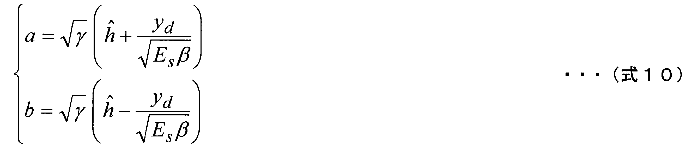
可観測値zの対数尤度比を算出する式を導出するために、まず、式8を次式9のように変形する。式9において、aおよびbは式10で表わされる。さらに、式10におけるγとβを、式11とすることで、式9におけるa、bは、独立なガウス変数となる。


式11におけるσest
2は、実チャネルhとチャネル推定値h(ハット)の平均2乗誤差(Mean Square Error; MSE)である。すなわち、σest
2は、チャネル推定値
h(ハット)の誤差の大きさを表す値である。σest 2は、チャネル推定方法に依存するが、例えばLSチャネル推定の場合、式12で表される。このため、チャネル推定方法がLSチャネル推定の場合、βは、式13となる。なお、Epは、パイロット信号の平均送信電力スペクトル密度である。
h(ハット)の誤差の大きさを表す値である。σest 2は、チャネル推定方法に依存するが、例えばLSチャネル推定の場合、式12で表される。このため、チャネル推定方法がLSチャネル推定の場合、βは、式13となる。なお、Epは、パイロット信号の平均送信電力スペクトル密度である。


また、aおよびbは独立なガウス変数であることから、zはaおよびbの絶対値によって一意に決定されるため、次式14の関係を満たす。

次に、zのLLR(λz)は式14を用いて次式15で表わされる。

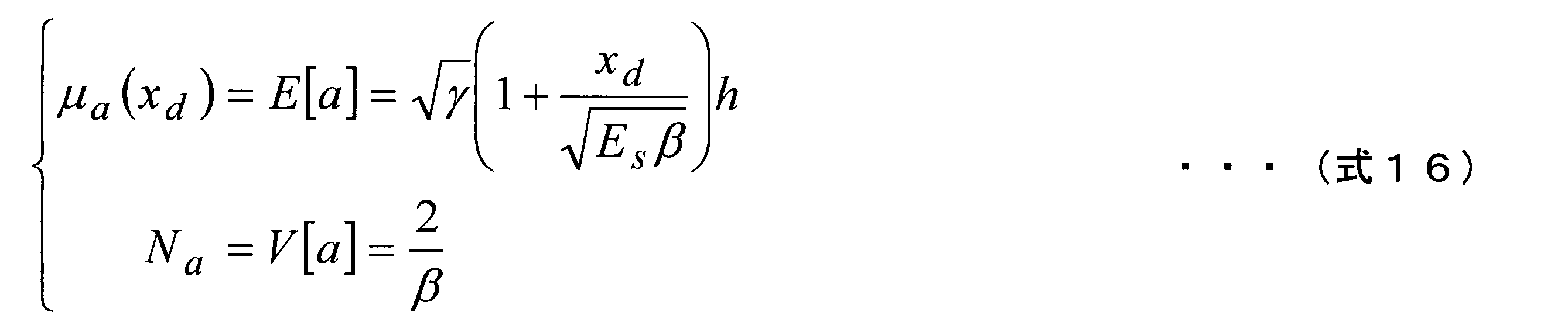
ここで、式10のaの平均値μaと分散Na、bの平均値μbと分散Nbは、それぞれ式16、式17で与えられる。

ここで、aとbで分散は同一となるため、Na=Nb=Nabと置く。上記の平均と分散より、p(a|xd)は次式18で与えられる。

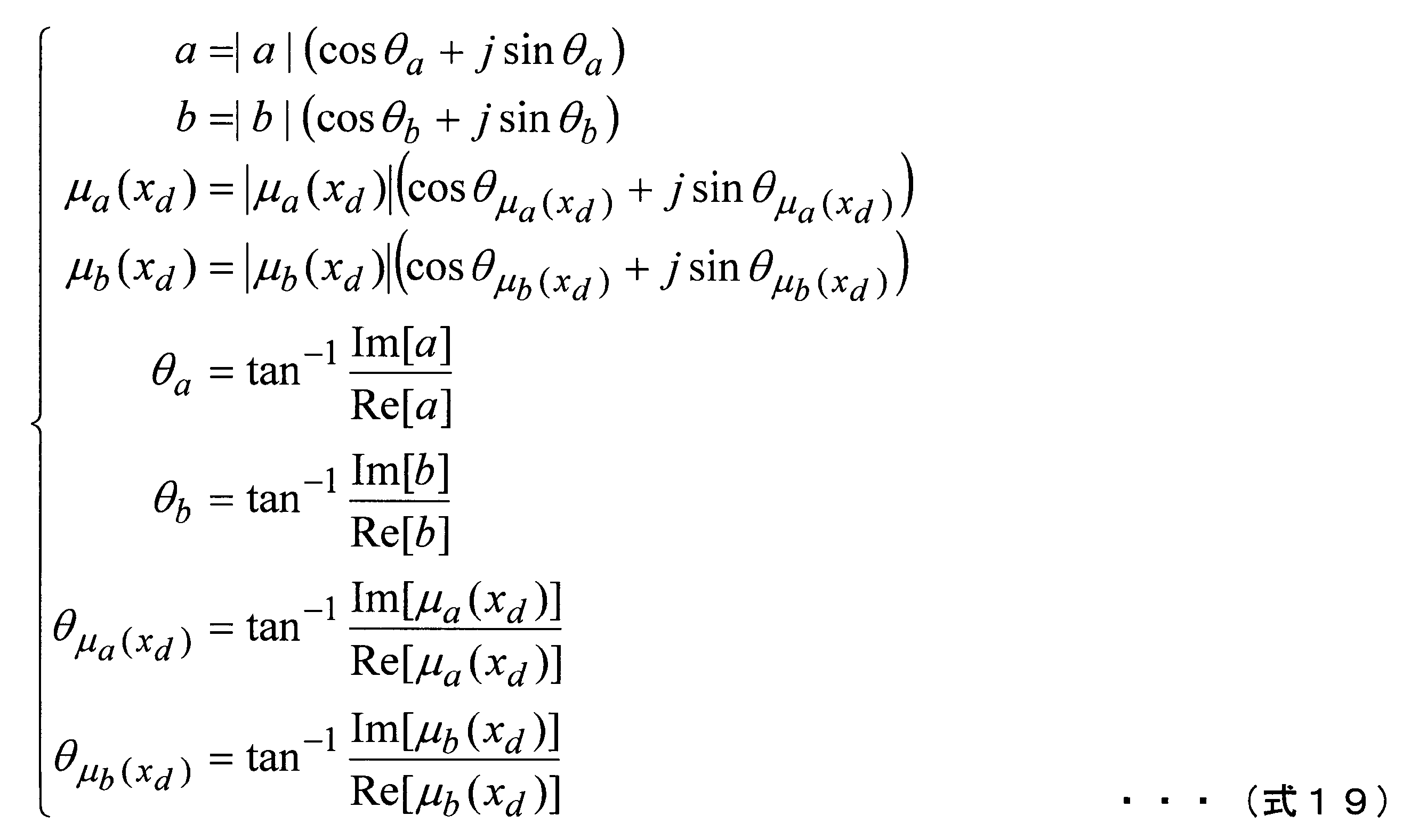
式15のLLRはaの絶対値のみで表わされるため、式18において、位相に対する周辺積分を行うことで、式20を得る。式20におけるI0(x)は第1種0次変形ベッセル関数であり、次式で表わされる。


bについても同様に算出することで、式15は次式22のように変形できる。

なお、β=1の場合、つまり受信したデータ信号に含まれる雑音電力スペクトル密度と伝搬路推定値のMSE(平均二乗誤差)が等しい場合(LSチャネル推定においてはデータ信号と参照信号の平均送信電力が等しい場合)には、式22は次式23となる。

ここで、第1種0次変形ベッセル関数I0に、次式24の近似式を用いることができる。
あるいは、次式25の近似を行うこともできる。
あるいは、次式25の近似を行うこともできる。


本実施形態における復調部407は、上述の式22を用いて復調処理を行う。なお、式24で示した第1種0次変形ベッセル関数の近似は必ずしも行う必要はなく、実際に計算してもよい。なお、式22、23、25など、復調部407が用いる式には未知数であるチャネル値hが含まれているが、本実施形態では、復調部407は、このチャネル値hにチャネル推定値h(ハット)を代入して演算する。いずれの式においても、チャネル値hの絶対値のみを用いており、位相は影響しないことから、これらの式において、チャネル値hとしてチャネル推定値h(ハット)を代入しても、発生する誤差は小さく、大きな特性の劣化は起きない。
次に、β=1の場合に復調部407が行なう処理、すなわち式23を用いる場合について、図面を用いて説明を行う。なお、β≠1の場合には、式23ではなく式22によってLLRを算出する必要があるため、復調部407の構成は図5とは異なる構成を取るが説明は省略する。図5は、β=1であるときの復調部407の構成の一例を示す概略ブロック図である。復調部407は、MSE設定部501、第1の変数算出部502、絶対値取得部503、第2の変数算出部504、絶対値取得部505、絶対値取得部506、LLR算出部507を含んで構成される。
復調部407には、データ信号抽出部405からデータ信号ydが入力されるとともに、チャネル推定部406からチャネル推定値h(ハット)、平均雑音電力スペクトル密度N0が入力される。これらのうち、データ信号ydは、第1の変数算出部502と第2の変数算出部504に入力される。また、チャネル推定値h(ハット)は、第1の変数算出部502と第2の変数算出部504、絶対値取得部506に入力される。また図示はしていないが平均雑音電力スペクトル密度が第1の変数算出部502、第2の変数算出部504およびLLR算出部507に入力される。
第1の変数算出部502は、式10に基づいてaの値を算出する。第2の変数算出部504は、式10に基づいてbの値を同様に算出する。第1の変数算出部502および第2の変数算出部504で算出された値a、bは、それぞれ絶対値取得部503および504に入力される。絶対値取得部503、505は、複素数で表わされている値a、bに対して、その絶対値を得る処理を適用する。算出された絶対値は、LLR算出部507に入力される。
一方、チャネル推定部406から出力されたチャネル推定値h(ハット)は、絶対値取得部506にも入力される。絶対値取得部506は、入力されたチャネル推定値h(ハット)にも、同じく絶対値を得る処理を適用する。ここで算出されたチャネル推定値の絶対値はLLR算出部507に入力される。
LLR算出部507は、絶対値取得部503、505、506から入力された絶対値およびチャネル推定部406から入力された平均雑音電力スペクトル密度と式23を用いてLLRの算出を行い、得られたLLRをデインターリーブ部408に入力する。なお第1種0次変形ベッセル関数は式24や式25等の近似を用いて算出することができる。
ところで、チャネル推定値が理想的に求められる場合、LLRはガウス分布に従い、かつLLRの平均値と分散の比は1:2となる。この比を満たす時、一貫性条件を満たすと呼ぶ。一方、本実施形態のLLR算出法を用いた場合、LLRはガウス分布に従うものの一貫性条件を満たさない。
ターボ復号器などの復号器では、この一貫性条件により平均値と分散の比が1:2となることを利用して状態遷移確率を算出することが一般的だが、本実施形態のLLR算出法では一貫性条件を満たさず、受信電力によって平均と分散の比が異なる。そこで、本実施形態における復号部409は、復号部409内に、各瞬時SNR(Signal to Noise power Ratio)における平均値と分散の比をテーブル化して保持し、チャネル推定部406が算出する瞬時受信SNRに応じて平均と分散の比を参照し、状態遷移確率に反映させる。
なお、各SNRにおける平均値と分散の比は、シミュレーションなどにより、予め算出しておいたもの記憶しておく。これにより、平均値と分散の比を、常に1:2として算出するよりも適切な状態遷移確率によって復号処理を行うことができる。ただし、常に1:2と近似を行い、従来と同様の復号処理を行ってもよい。
なお、各SNRにおける平均値と分散の比は、シミュレーションなどにより、予め算出しておいたもの記憶しておく。これにより、平均値と分散の比を、常に1:2として算出するよりも適切な状態遷移確率によって復号処理を行うことができる。ただし、常に1:2と近似を行い、従来と同様の復号処理を行ってもよい。
このように、本実施形態では、チャネル推定値に含まれる誤差の大きさを表すσest
2を用いたLLR算出法を用いることで、チャネル推定時において、LLR算出時に2つの雑音があるにもかかわらず、ガウス分布に従うとする近似を避けて、LLRを算出することで、誤差を抑えることができる。このLLRを用いて誤り判定や誤り訂正復号を行うことで、従来のLLR算出法を用いた場合よりもビット誤り率を改善することができる。
<変形例1>
上記実施形態では変調方式としてBPSKを用いる場合について説明を行ったが、変形例としてQPSKを用いた場合について以下で説明を行う。すなわち、基地局装置101の変調部203が、QPSKによって符号化ビット系列を変調シンボルに変換する場合の、端末装置102の復調部407が行う処理を説明する。
変調方式がQPSKであるとき、QPSKシンボルを構成する2ビットをそれぞれc0、c1とする。このとき、xd∈{χ0、χ1、χ2、χ3}は次式26で表わされる。
なお、QPSKシンボルとビット値との対応付けには、グレイマッピングを用いる。
上記実施形態では変調方式としてBPSKを用いる場合について説明を行ったが、変形例としてQPSKを用いた場合について以下で説明を行う。すなわち、基地局装置101の変調部203が、QPSKによって符号化ビット系列を変調シンボルに変換する場合の、端末装置102の復調部407が行う処理を説明する。
変調方式がQPSKであるとき、QPSKシンボルを構成する2ビットをそれぞれc0、c1とする。このとき、xd∈{χ0、χ1、χ2、χ3}は次式26で表わされる。
なお、QPSKシンボルとビット値との対応付けには、グレイマッピングを用いる。

つまり、{c0、c1}={0、0}の時、変調点はχ0、{c0、c1}={0、1}の時、変調点はχ0、{c0、c1}={1、0}の時、変調点はχ0、{c0、c1}={1、1}の時、変調点はχ0となる。
まず、チャネル推定値hハットを用いたビットc0のLLRの算出式を、次式27に基づき導出する。

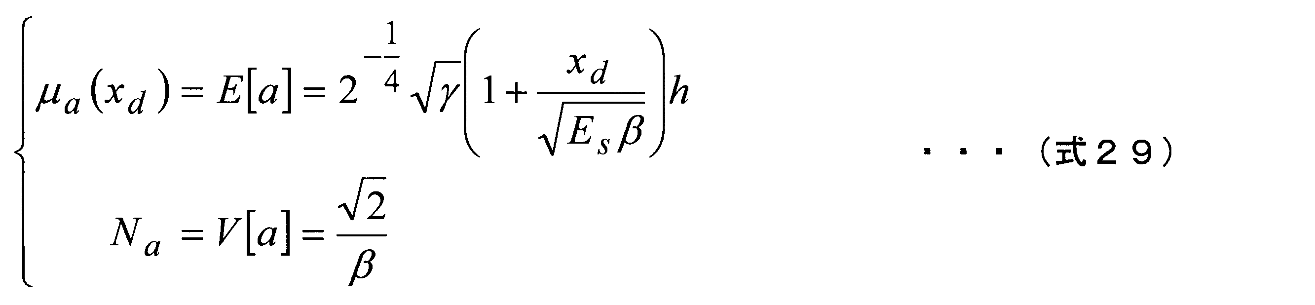
ここでaおよびbは、独立なガウス変数であり、式28で表される。また、aの平均値μaと分散Naはそれぞれ式29で、bの平均値μbと分散Nbはそれぞれ式30で与えられる。

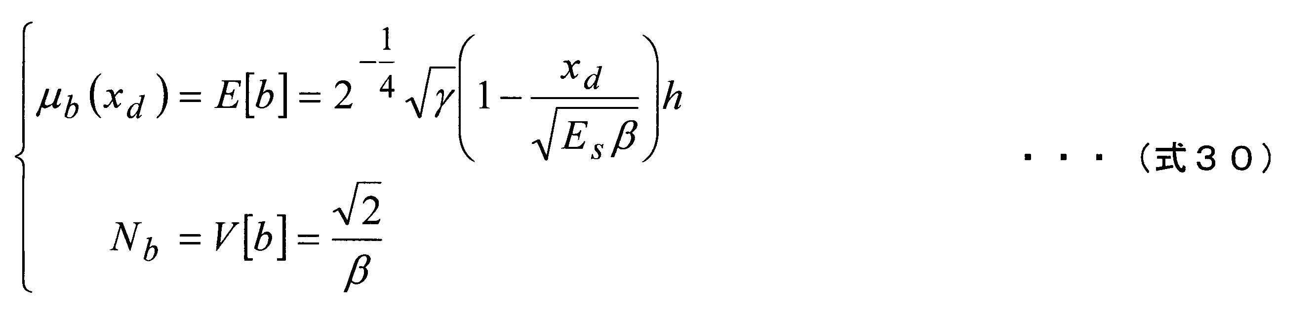
ここで、aとbで分散は同一となるため、Na=Nb=Nabとする。上記の平均と分散より、式22の算出と同様にすると、c0=0となる変調点はχ0およびχ1、またc0=1となる変調点はχ2およびχ3であることから、次式31が得られる。復調部407は、この式31を、ビットc0のLLRの算出式として用いる。

以上、ビットc0について説明を行ったが、次にビットc1について説明を行う。復調部407において、チャネル推定時のビットc1のLLRは次式32に基づいて行われる。

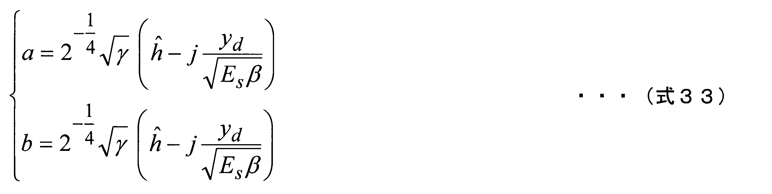
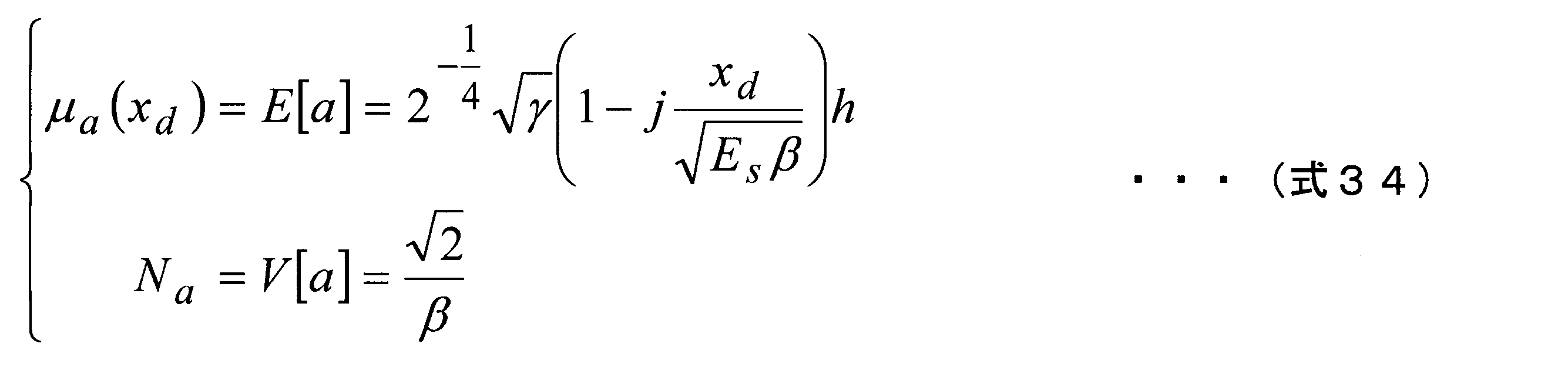
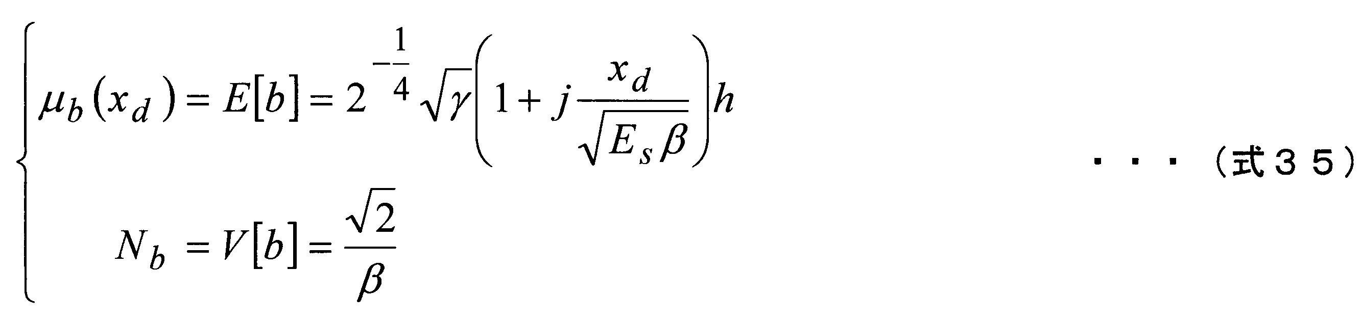
ここでaおよびbは独立なガウス変数であり、式33で表される。また、aの平均値μaと分散Naはそれぞれ式34で、bの平均値μbと分散Nbは、c1=0となる変調点はχ0およびχ2、またc1=1となる変調点はχ1およびχ3であることから、それぞれ式35で与えられる。なお、式33、式34、式35におけるjは、虚数単位である。
ここで、aとbで分散は同一となるため、Na=Nb=Nabとする。上記の平均と分散より、式22の算出と同様にすると、次式36が得られる。復調部407は、この式36を、ビットc1のLLRの算出式として用いる。
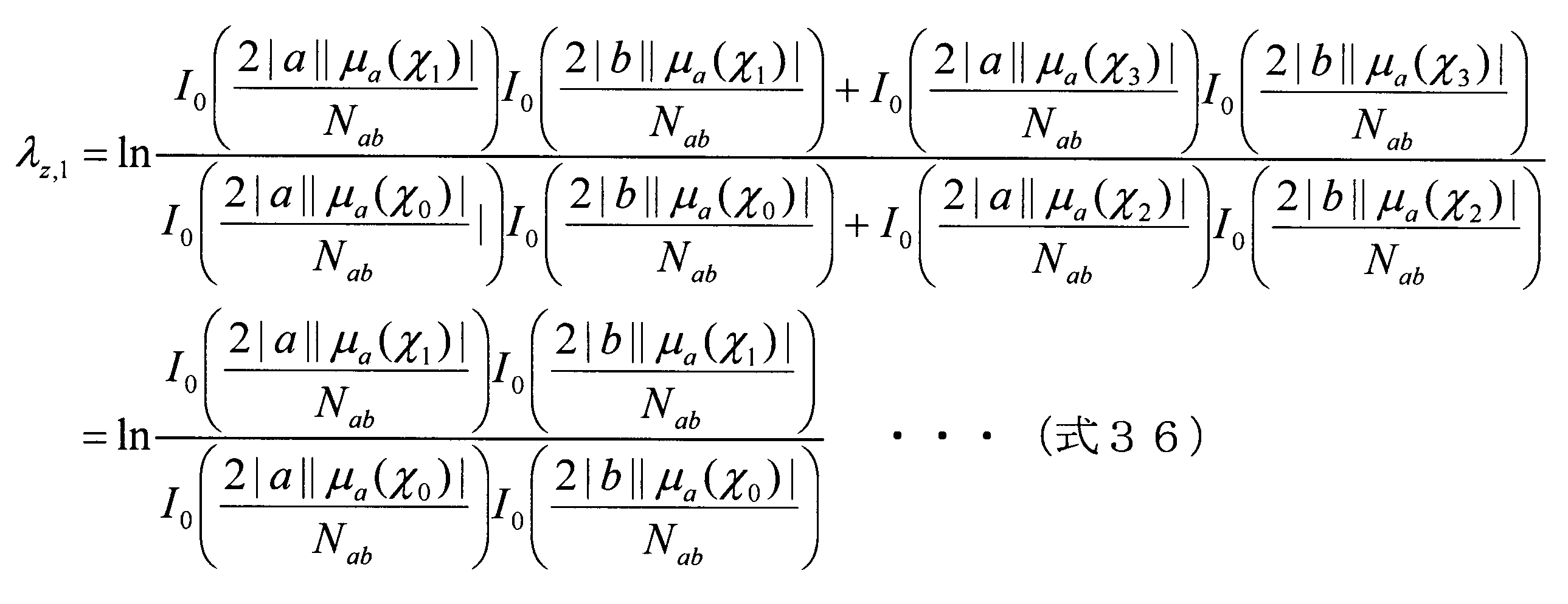
このように復調部407は、QPSKの各ビット(c0およびc1)のLLRを、式31および式36によって算出することができる。同様に、16QPSKや16QAM(Quadrature Amplitude Modulation)等の他の変調方式を用いた場合にも、適用することができる。
<変形例2>
上記実施形態およびその変形例1では、チャネル推定部406がチャネル推定法として、LSチャネル推定を用いる場合について説明を行った。しかしながら、本実施形態やその変形例はチャネル推定値を用いた新しいLLR算出法を用いているが、チャネル推定法はLSチャネル推定に限定されず、どのようなものであってもよい。そこで他のチャネル推定法として、従来からよくチャネル推定法として用いられる、雑音除去(Noise Eliminated、NE)基準チャネル推定を用いた場合のLLR算出法について説明を行う。
上記実施形態およびその変形例1では、チャネル推定部406がチャネル推定法として、LSチャネル推定を用いる場合について説明を行った。しかしながら、本実施形態やその変形例はチャネル推定値を用いた新しいLLR算出法を用いているが、チャネル推定法はLSチャネル推定に限定されず、どのようなものであってもよい。そこで他のチャネル推定法として、従来からよくチャネル推定法として用いられる、雑音除去(Noise Eliminated、NE)基準チャネル推定を用いた場合のLLR算出法について説明を行う。
初めに、チャネル推定部406が行うNE基準チャネル推定について説明を行う。例えばOFDM伝送において、式1と同様に伝搬路の複素チャネル利得をH(k)とすると、チャネルベクトルHは、式37で表わされる。またLSチャネル推定によって得られるLSチャネル推定値ベクトルHLSは、式38で表わされる。HおよびHLSの時間応答(インパルス応答)hおよびhLSは、式39で表わされる。ここでFはNポイントのDFT行列である。


NE基準チャネル推定では、LSチャネル推定によって得られたインパスル応答に次式のフィルタリングを行うことにより、雑音除去を行ったインパルス応答ベクトルhNEを得る。

ここでフィルタWは1からL番目までの対角要素が1であり、その他の要素は0のK×Kの行列である。Lはチャネルのパス数であることが望ましいが、パス数の推定ができない場合、CP(あるいはガードインターバル)等、既定の長さに設定する。また要素は1である必要はなく、ガードバンドがある場合などは、ガードバンドを考慮した重み付けを行うことも可能である。得られた雑音除去を行ったインパルス応答ベクトルhNEを周波数領域に変換することで雑音除去を行ったチャネル推定ベクトルHNEを得る。

NE基準チャネル推定では、雑音の電力をフィルタWに含まれる1の要素数に応じて抑圧することができる。例えば、上記のように1の要素数がLであり、フィルタWのサイズがK×Kのとき、雑音電力をL/Kに抑圧することができる。したがって、NE基準チャネル推定のMSEは次式42で表わされる。このとき、βは、式43となる。


復調部407は、第1の実施形態における式13の代わりに式43を用いる他、h(ハット)の代わりにHNE(k)(ハット)を用いることで、チャネル推定部406がNE基準チャネル推定を用いている場合にも、ビットLLRに含まれる誤差を抑えることができる。なお、上記ではフィルタWが1からL番目までの対角要素が1であり、その他の要素が0である場合を示したが、時間領域での矩形フィルタの乗算は、周波数領域におけるsinc関数の畳み込み演算と等価である。つまり、NE基準チャネル推定は周波数領域での重み付け平均化処理と呼ぶことができる。平均化によるチャネル推定精度の向上は、周波数のみならず、時間、符号やアンテナに相関がある場合アンテナ方向にも行ってもよい。
なお、LS基準やNE基準以外のチャネル推定法を用いた場合でも、チャネル推定値h(ハット)の平均2乗誤差MSEの値を理論的に算出する、あるいはシミュレーションなどによって経験的に得た値を保持しておき、該値を用いてβを算出すれば、上述のLLR算出法は、どのチャネル推定法を用いた場合にも適用できる。なお、本実施形態や変形例のように、チャネル推定値h(ハット)の平均2乗誤差MSEを直接的には求めず、該MSEの算出式を、βの定義式に代入して得られる式に、Es、Ep、N0などを代入して、βを算出するようにしてもよいし、Es、Ep、N0などの値の組み合わせに応じたβの値を、シミュレーションなどによって予め求めておいたものを記憶し、該値を用いるようにしてもよい。
本実施形態のLLR算出法による計算機シミュレーションの結果を図6、図7に示す。
図6は、チャネル推定としてLS基準チャネル推定を用いたときのシミュレーション結果であり、図7は、チャネル推定としてNE基準チャネル推定を用いたときのシミュレーション結果である。図6において横軸は平均送信電力スペクトル密度Es/平均雑音スペクトル密度N0(dB)、縦軸はフレーム誤り率(Frame Error Rate;FER)である。シミュレーション条件としては、64サブキャリア、CP長16ポイント、変調方式はQPSK、誤り訂正符号は符号化率1/2の拘束長4のターボ符号、復号器は繰り返し数8回の修正項付きMax-Log-MAP復号、チャネルモデルは減衰定数2dBの12パスのレイリーフェージングとしている。またフレーム構成は図3のものではなく、1パイロットODFMシンボルと16データOFDMシンボルで1フレームが構成されるものとしている。図6、図7において十字のプロット(+)はチャネル推定が完全な場合を示しており、三角(▲)は従来のLLR算出法を用いた場合、丸(○)は本実施形態のLLR算出法を用いた場合の特性である。
図6は、チャネル推定としてLS基準チャネル推定を用いたときのシミュレーション結果であり、図7は、チャネル推定としてNE基準チャネル推定を用いたときのシミュレーション結果である。図6において横軸は平均送信電力スペクトル密度Es/平均雑音スペクトル密度N0(dB)、縦軸はフレーム誤り率(Frame Error Rate;FER)である。シミュレーション条件としては、64サブキャリア、CP長16ポイント、変調方式はQPSK、誤り訂正符号は符号化率1/2の拘束長4のターボ符号、復号器は繰り返し数8回の修正項付きMax-Log-MAP復号、チャネルモデルは減衰定数2dBの12パスのレイリーフェージングとしている。またフレーム構成は図3のものではなく、1パイロットODFMシンボルと16データOFDMシンボルで1フレームが構成されるものとしている。図6、図7において十字のプロット(+)はチャネル推定が完全な場合を示しており、三角(▲)は従来のLLR算出法を用いた場合、丸(○)は本実施形態のLLR算出法を用いた場合の特性である。
LSチャネル推定を行った図6によると、本実施形態のLLR算出法は、従来のものと比べてFER=0.01において0.4dBの改善効果、NEチャネル推定を行った図7によると、0.15dBの改善効果がある。このように本実施形態のLLR算出法は、伝送特性の向上に効果があることが確認できる。
[第2の実施形態]
第1の実施形態では参照信号によって得られたチャネル推定値によってデータを復調し、さらに復号を行う場合について説明を行った。ところで、復号後のデータの信頼性が高い場合、データ信号を参照信号と見なし、再度チャネル推定を行う判定帰還型チャネル推定(繰り返しチャネル推定)が有効である。繰り返しチャネル推定を適用することで、データ信号を参照信号として扱うことができる。この結果、見かけ上、参照信号の数を増加させることになり、大幅にチャネル推定精度を向上させることができるためである。なお、本実施形態も、LTEのダウンリンク、つまりOFDM伝送に適用した場合を例に説明を行うが、第1の実施形態と同様、チャネル推定を行うシステムであれば、どのような通信システムに対しても適用可能である。
第1の実施形態では参照信号によって得られたチャネル推定値によってデータを復調し、さらに復号を行う場合について説明を行った。ところで、復号後のデータの信頼性が高い場合、データ信号を参照信号と見なし、再度チャネル推定を行う判定帰還型チャネル推定(繰り返しチャネル推定)が有効である。繰り返しチャネル推定を適用することで、データ信号を参照信号として扱うことができる。この結果、見かけ上、参照信号の数を増加させることになり、大幅にチャネル推定精度を向上させることができるためである。なお、本実施形態も、LTEのダウンリンク、つまりOFDM伝送に適用した場合を例に説明を行うが、第1の実施形態と同様、チャネル推定を行うシステムであれば、どのような通信システムに対しても適用可能である。
本実施形態における基地局装置101は、第1の実施形態の基地局構成と同一の構成とすることができるため、説明を省略する。基地局装置101が送信した信号は端末装置102aで受信される。図8は、本実施形態における端末装置102aの受信機構成の一例を示す概略ブロック図である。端末装置102aは、受信アンテナ401、無線受信部402、CP除去部403、FFT(Fast Fourier Transform;高速フーリエ変換)部404、データ信号抽出部405、チャネル推定部406a、復調部407a、デインターリーブ部408、復号部409a、インターリーブ部801、レプリカ生成部802、レプリカ絶対値補正部803、参照信号生成部804、フレーム構成部805を含んで構成される。なお、端末装置102aは、これらの各部に加えて、基地局装置101に無線信号を送信する送信部など、基地局装置と無線通信する端末装置が一般に有する構成を含んで構成されるが、ここでは図示および説明を省略する。
基地局装置101から送信された信号は、端末装置102aの受信アンテナ401で受信される。なお本実施形態において、端末装置102aの受信アンテナ数は1とするが、複数の受信アンテナを備え、受信アンテナダイバーシチ等、公知の技術を適用してもよい。受信アンテナで受信された信号は無線受信部402へ入力される。無線受信部402は、入力された信号に対してダウンコンバージョン、帯域制限フィルタリング、A/D(Analog-to-Digital)変換等の処理を適用する。
無線受信部402の出力は、CP除去部403に入力される。CP除去部403は、受信信号を(NFFT+NCP)ポイント毎に区切り、(NFFT+NCP)ポイントの受信信号の先頭からNCPポイントを除去する。CP除去部403が出力するNFFTポイント毎の信号は、FFT部404に入力される。FFT部404は、NFFTポイントのFFTを適用することで、入力されたNFFTポイント毎の時間領域信号を周波数領域信号(受信周波数領域信号)に変換する。FFT部404の出力はデータ信号抽出部405およびチャネル推定部406aに入力される。
データ信号抽出部405は、受信周波数領域信号の中から、図3のフレーム構成に従い、受信データ信号を抽出し、復調部407aに入力する。復調部407aは、データ信号抽出部405から入力された受信データ信号に対して、チャネル推定部406aから入力されたチャネル推定値を用いて、チャネルの影響の補償と、チャネル補償後のシンボル系列をビットLLRの系列に変換する処理が適用される。なお、チャネル推定部406aからチャネル推定値と共に入力される平均雑音電力スペクトル密度を用いたチャネル補償(例えばMMSE基準)を行ってもよい。本実施形態における復調部407aが行う処理の詳細は、後述する。
復調部407aが出力するLLRはデインターリーブ部408に入力され、基地局装置101のインターリーブ部202で行われたインターリーブを元に戻す処理が適用される。デインターリーブ部408の出力は復号部409aに入力され、復号部409aは、基地局装置101で適用された誤り訂正符号に基づいて、第1の実施形態における復号部409と同様にして復号を行う。復号処理で得られる符号化ビットの事後LLRはインターリーブ部801に入力される。なお、インターリーブ部801に入力されるLLRは外部LLRであってもよい。なお、復号部409aが、符号化ビットの事後LLRをインターリーブ部801に入力することで、端末装置102aは、繰り返しチャネル推定を行うが、所定の繰り返し数に達したときなどの繰り返しの終了条件を満たしているときは、復号部409aは、復号処理の硬判定結果を復元ビット系列Tとして出力する。
インターリーブ部801は、復号部409aから入力された符号化ビットLLRに対して、基地局装置101のインターリーブ部202と同一の並び替え処理を適用し、インターリーブ後の符号化ビットLLRをレプリカ生成部802に入力する。レプリカ生成部802は、入力された符号化ビットLLRと、基地局装置101の変調部203で適用された変調方式によって、送信信号のシンボルレプリカ(ソフトレプリカ)を生成し、レプリカ絶対値補正部803に入力する。
レプリカ絶対値補正部803は、入力されたシンボルレプリカの絶対値の補正を行ない、補正したシンボルレプリカをフレーム構成部805に入力する。レプリカ絶対値補正部803は、例えばシンボルレプリカの絶対値が、所定の値(閾値)以上の場合、シンボルレプリカの大きさを既定値(例えば1)とし、所定の値より小さい場合、シンボルレプリカの大きさを0とする。レプリカ絶対値補正部803は、シンボルレプリカの大きさの補正を行うことで、尤度の低いシンボルレプリカをチャネル推定に用いないようにする。この結果、チャネル推定精度が劣化するのを防ぐことができる。
なお上記の例では、シンボルレプリカの絶対値が所定の値より小さい場合、シンボルレプリカの大きさを0としたが、0とせず、絶対値が所定の値より小さいシンボルレプリカを削除し、絶対値が所定の値より大きいシンボルレプリカのみをフレーム構成部805に入力してもよい。また、本実施形態では所定の値を1つ用意し、シンボルレプリカを0または1の2値の振幅に量子化する場合について説明を行うが、所定の値を複数用意し、3値以上の振幅に量子化する処理を行ってもよいし、レプリカ絶対値補正部803が絶対値の補正を行なわい、つまりソフトレプリカをそのまま用いることも可能である。補正が行なわれたシンボルレプリカは、フレーム構成部805に入力される。
参照信号生成部804は、基地局装置101の参照信号生成部204と同一の参照信号を生成する。フレーム構成部805は、参照信号生成部804から入力される参照信号と、レプリカ絶対値補正部803から入力されるレプリカを用いて、基地局装置101のフレーム構成部205と同様のフレーム構成(例えば図3)のフレームを構成する。構成されたフレームはチャネル推定部406aと、復調部407aに入力される。チャネル推定部406aは、FFT部404から入力された受信周波数領域信号を用いてチャネル推定を行う。なお、チャネル推定部406aは、繰り返しチャネル推定の1回目では、受信周波数領域信号中の参照信号を、フレーム構成部805から入力されるフレームに配置された参照信号と比較してチャネル推定を行う。しかし、繰り返しチャネル推定の2回目以降では、チャネル推定部406aは、受信周波数領域信号中の参照信号およびデータ信号を、フレーム構成部805から入力されるフレームに配置された参照信号およびデータ信号のレプリカと比較してチャネル推定を行う。
繰り返しチャネル推定の2回目以降のチャネル推定について詳細に説明する。まず、図3のような送信フレーム構成を仮定し、第mOFDMシンボルの第kサブキャリアにおける受信信号をY(m)(k)とすると、第kサブキャリアにおける受信信号列Y(k)は次式44で表わされる。

例えばk=3の場合、Y(4)(3)とY(11)(3)は受信参照信号であり、他の要素は受信データ信号となる。他のサブキャリアにおいても同様であるため、以降、説明を簡単にするため、インデックスkは省略し、小文字を用いることとする。よって式44は次式45のように表わされる。

チャネル推定部406aは、次式46を計算することにより、各サブキャリアにおけるチャネル推定値h(ハット)を算出する。ここで、x(ハット)は送信信号のレプリカを表わし、参照信号が送信されるOFDM信号では、参照信号が入力され、式47の関係式を満たす。


式47において、M(ハット)はx(ハット)のデータシンボルの非ゼロ要素数(最大7)である。このように、本実施形態のチャネル推定部406aは、レプリカ絶対値補正部803に入力されるレプリカに関して、絶対値が大きなレプリカが多い場合、多くの受信データ信号を用いてチャネル推定を行うため、高精度なチャネル推定を行うことができる。一方、例えば絶対値が大きなレプリカが存在しない場合、参照信号のみを用いてチャネル推定を行うため、データの判定誤りによるチャネル推定精度の劣化を抑えることができる。
なお、式46ではチャネルの時変動がないことを仮定しているため、全シンボルを等利得合成し、1つのチャネル推定値を算出しているが、チャネルに時変動が存在する場合は等利得合成ではなく、重み付け合成を行い、OFDMシンボル毎のチャネル推定値を算出すればよい。例えば隣接シンボルにみの平均化や、MSEが最小となる重み付け、sinc関数、あるいは0次第1種ベッセル関数で重み付けなど、どのようなものであってもよい。
また、チャネル推定部406aは、チャネル推定値の他に平均雑音電力を算出する。これらの算出方法はどのようなものであってもよい。例えば平均雑音電力の推定は、何も送信が行なわれていないサブキャリア(ヌルサブキャリア)における受信電力を用いて算出してもよいし、参照信号が受信されるリソースエレメントにおいて、受信信号から、送信された参照信号にチャネル推定値を乗算した値を減算することで算出してもよい。チャネル推定部406aで算出されたチャネル推定値および平均雑音電力スペクトル密度は復調部407aおよび復号部409aに入力される。
次に本実施形態の特徴である、復調部407aでの処理について説明を行う。復調部407aにおけるBPSKを用いた第mOFDMシンボルのLLRの算出は、チャネル推定部406aから入力されるチャネル推定値を用いて、次式48に基づいて行われる。

ここでa(m)およびb(m)は独立なガウス変数であり、式49で表される。ここで、式49のaの平均値μaとbの平均値μbはそれぞれ式50で、aの分散Naは式51
で、bの分散Nbは式52で、与えられる。なお、式51、52におけるx(m)(ハット)は、フレーム構成部805が生成したフレーム中のm番目のOFDMシンボルである。
で、bの分散Nbは式52で、与えられる。なお、式51、52におけるx(m)(ハット)は、フレーム構成部805が生成したフレーム中のm番目のOFDMシンボルである。
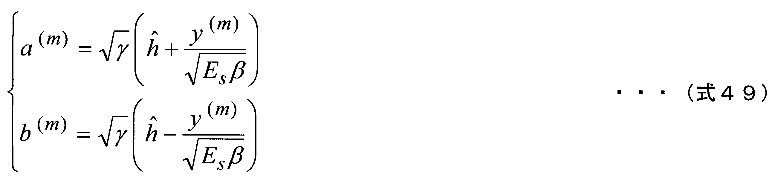

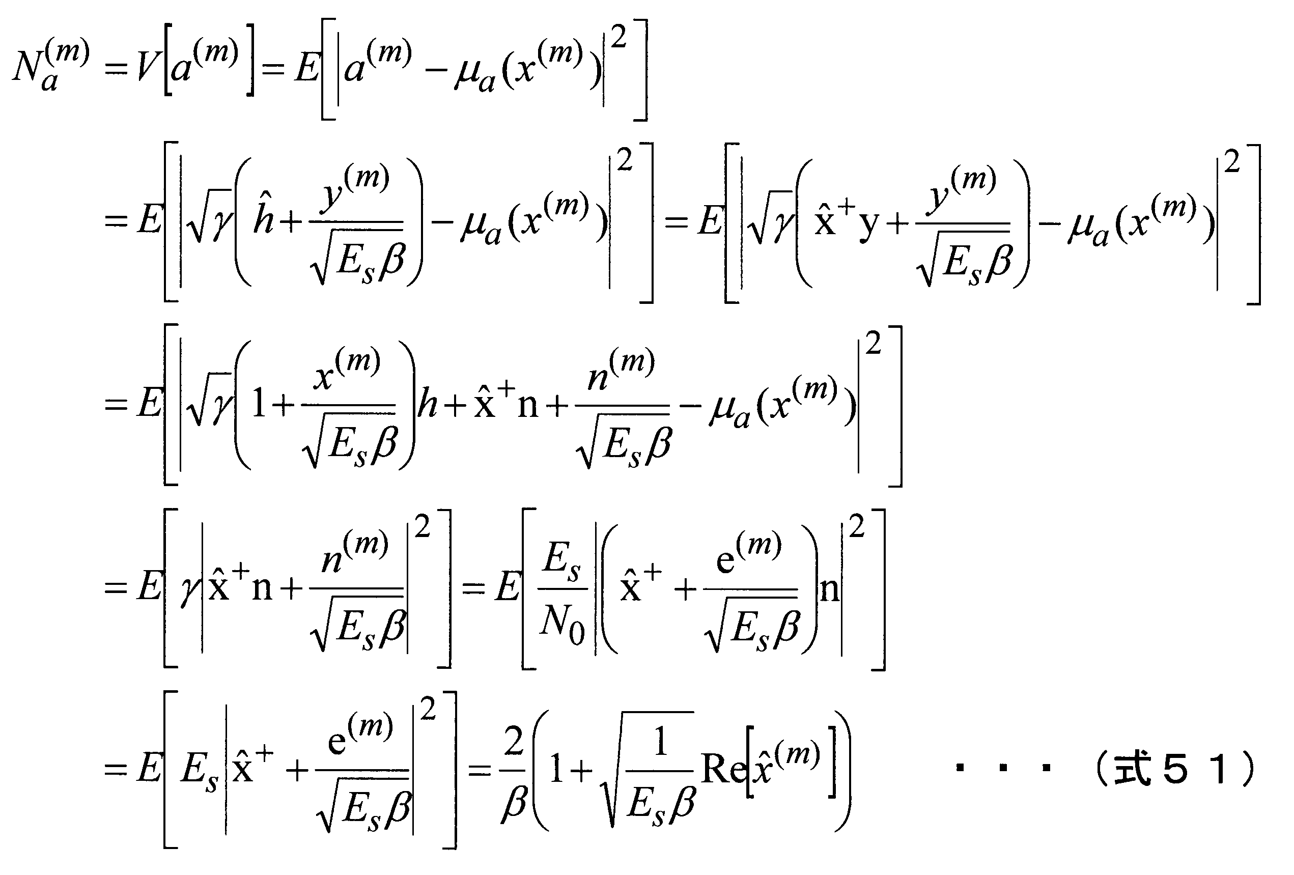

以上の平均と分散と次式53によって、第1の実施形態と同様、ビットLLRを算出できる。なお、e(m)はm番目の要素が1でそれ以外は0である1行7列の行ベクトル、nは各受信シンボルにおける雑音成分ベクトル(7行1列)である。

つまり、復調部407aは、チャネル推定部406aから入力されるデータ信号、参照信号、平均雑音電力スペクトル密度およびチャネル推定値と、データ信号抽出部405から入力される受信信号と、フレーム構成部805から入力されるシンボルとを用いて、式53を演算し、ビットLLRとしてデインターリーブ部408に出力する。例えばチャネル推定法がLSチャネル推定の場合、チャネル推定に用いることができる電力が繰り返しを行なわない場合はEpであったのに対し、硬判定を行ったデータ数だけ電力を増加させることができるため、チャネル推定誤差(MSE)は式54のようになる。したがって、βは、式55にて算出できる。


ただし、式54では硬判定時の判定誤りを考慮していないが、経験的な誤り率などのパラメータを考慮して補正を行ってもよい。また判定誤りに耐性を持たせるために、軟判定値を用いてもよい。
以上のように、本実施形態における端末装置102aは、繰り返しチャネル推定を用いてチャネル推定精度を向上させるとともに、復調処理結果のビットLLRに含まれる誤差を抑えることができる。このLLRを用いて誤り判定や誤り訂正復号を行うことで、従来のLLR算出法を用いた場合よりもビット誤り率を改善することができる。
本実施形態では、データのLLRをチャネル推定のみに使用する方法を例に説明を行った。しかし、シンボル間干渉やMIMOにおけるストリーム間干渉等の干渉が存在する場合に、データのLLRをチャネル推定とともに、干渉のレプリカの生成にも使用し、受信信号から減算することで干渉をキャンセルする処理を適用してもよい。
<変形例1>
上記では変調方式としてBPSKを用いる場合について説明を行ったが、変形例1として繰り返しチャネル推定において、データの変調方式がQPSKである場合、すなわち変調部203がQPSKによって変調シンボルを生成する場合の復調部407aの処理について説明する。変調方式がQPSKであるとき、QPSKシンボルを構成する2ビットをそれぞれc0、c1とする。このとき、送信データシンボルxd∈{χ0、χ1、χ2、χ3}は次式56で表わされる
上記では変調方式としてBPSKを用いる場合について説明を行ったが、変形例1として繰り返しチャネル推定において、データの変調方式がQPSKである場合、すなわち変調部203がQPSKによって変調シンボルを生成する場合の復調部407aの処理について説明する。変調方式がQPSKであるとき、QPSKシンボルを構成する2ビットをそれぞれc0、c1とする。このとき、送信データシンボルxd∈{χ0、χ1、χ2、χ3}は次式56で表わされる

繰り返しチャネル推定時の、第kサブキャリア第mOFDMシンボルにおける、c0のビットLLRは、次式57のように置くことができる。
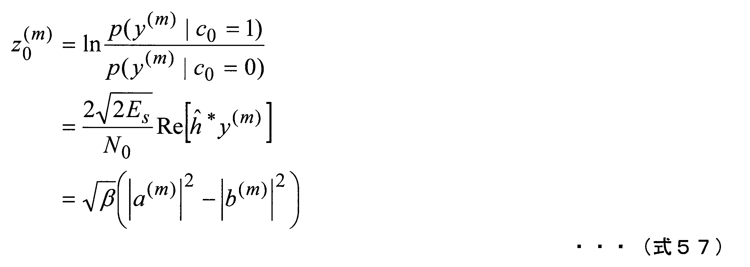
ここでa(m)およびb(m)は独立なガウス変数であり、式58で表される。また、a(m)の平均値μaと分散Naはそれぞれ式59で、b(m)の平均値μbと分散Nbはそれぞれ式60で与えられる。


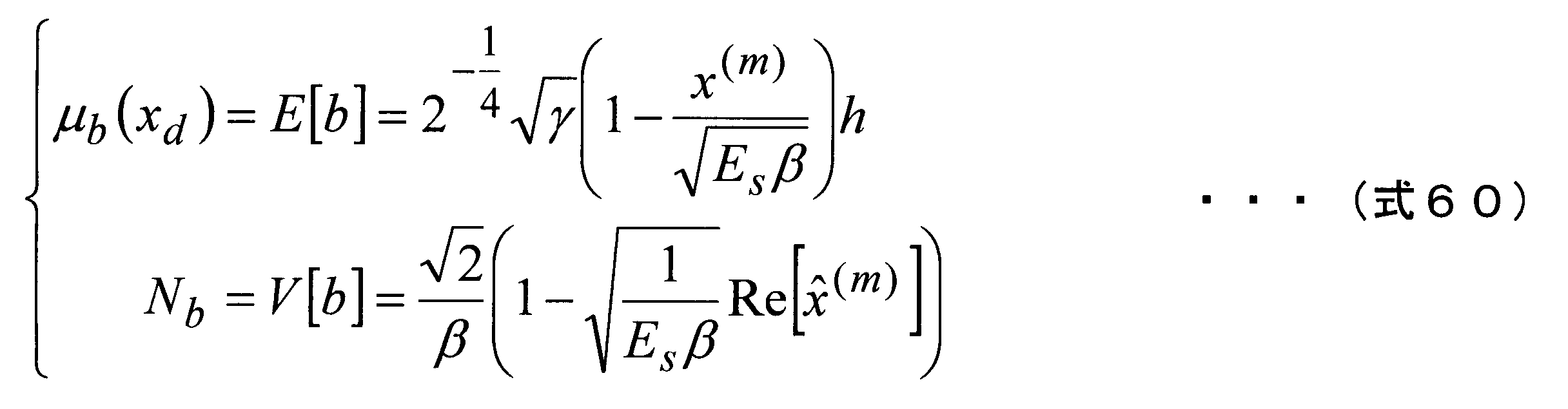
上記の平均と分散より、式53の算出と同様にして、次式61を得る。復調部407aは、この式61を、ビットc0のLLRの算出式として用いる。ただし、式61におけるf(xq)は、式62で表される。

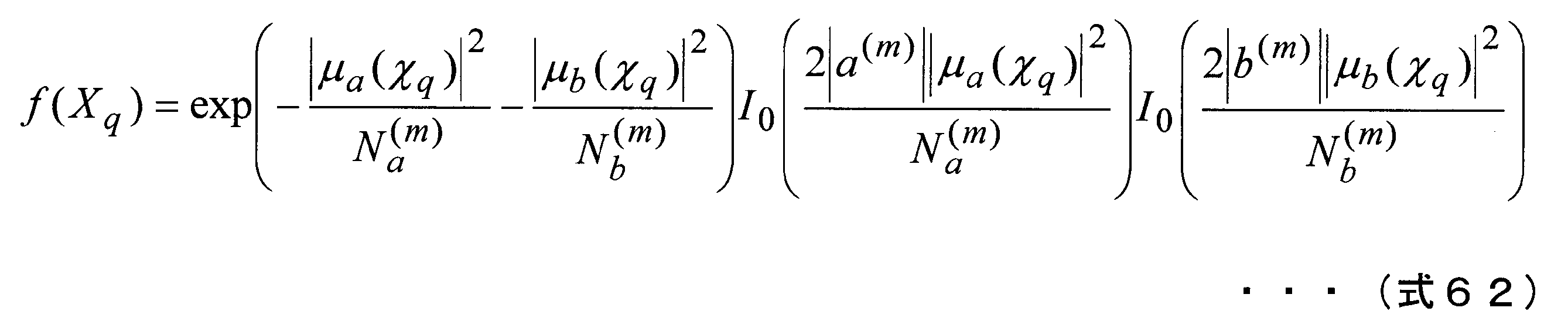
次にビットc1について説明する。繰り返しチャネル推定時の、第kサブキャリア第mOFDMシンボルにおける、c1のビットLLRは、次式63のように置くことができる。
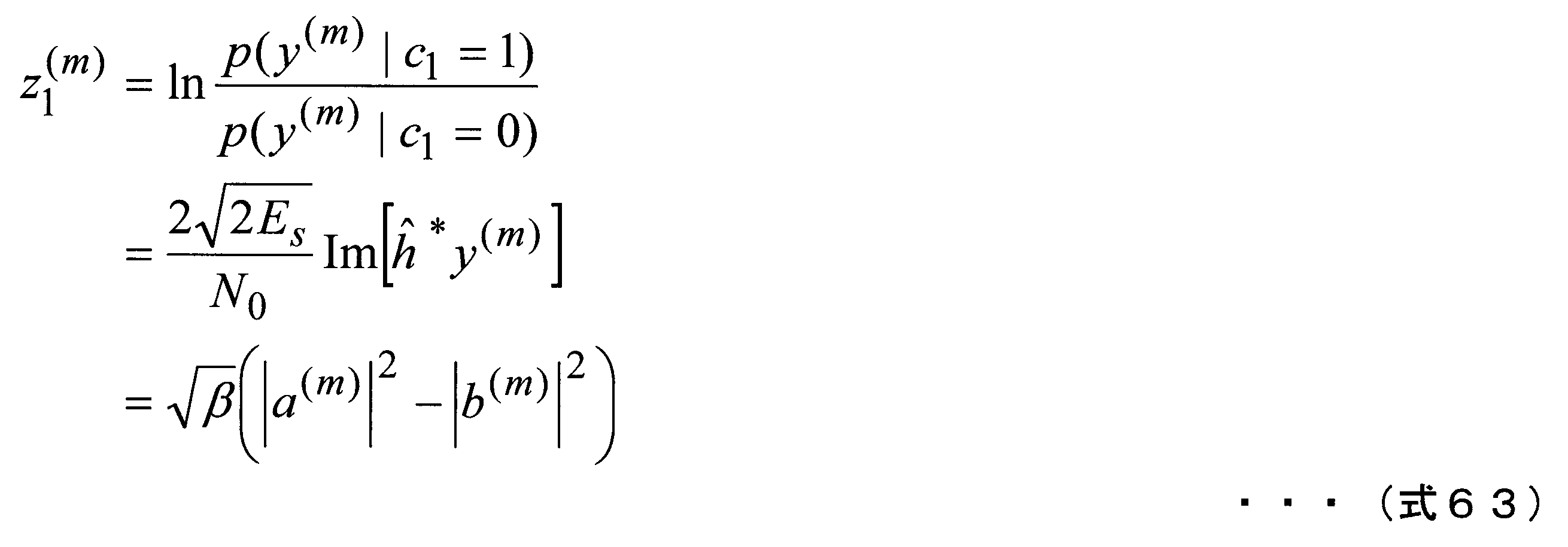
ここでa(m)およびb(m)は独立なガウス変数であり、式64で表される。a(m)の平均値μaと分散Naはそれぞれ式65で、b(m)の平均値μbと分散Nbはそれぞれ式66で、与えられる。


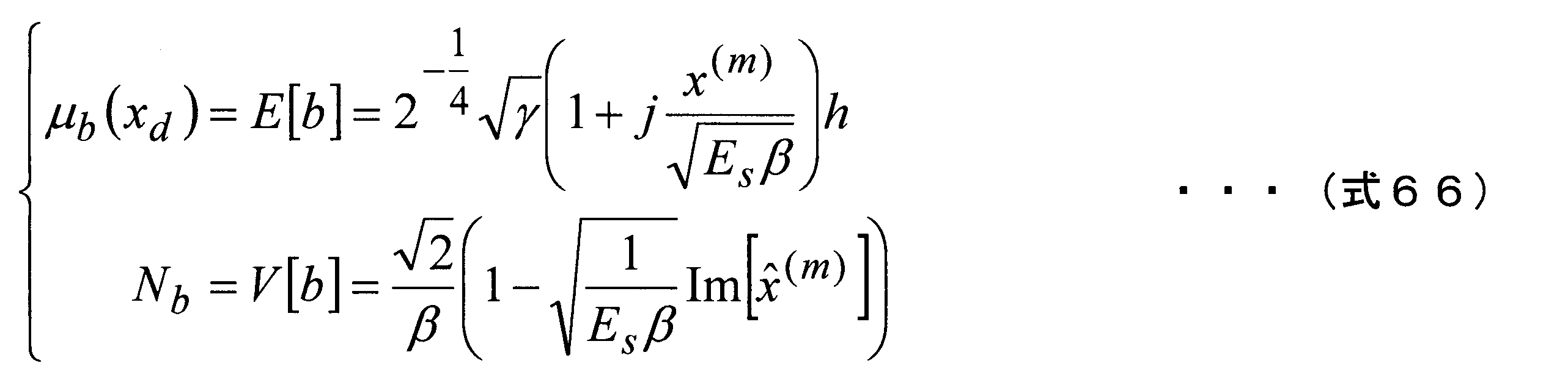
上記の平均と分散より、式53の算出と同様にして、次式67を得る。復調部407は、この式67を、ビットc1のLLRの算出式として用いる。

このように復調部407aは、QPSKの各ビット(c0およびc1)のLLRを、式61および式67によって算出することができる。同様に、16QAM(Quadrature Amplitude Modulation)等の他の変調方式を用いた場合にも、適用することができる。
<変形例2>
第2の実施形態およびその変形例1では、繰り返しチャネル推定の中のチャネル推定法として、LSチャネル推定を用いた場合について説明を行った。しかしながら、本実施形態は繰り返しチャネル推定時における新しいLLR算出法を用いているが、繰り返しチャネル推定の中で行うチャネル推定法はLSチャネル推定に限定されず、どのようなものであってもよい。そこで他のチャネル推定法として、雑音除去(Noise Eliminated、NE)基準チャネル推定を用いた場合のLLR算出法について説明を行う。
第2の実施形態およびその変形例1では、繰り返しチャネル推定の中のチャネル推定法として、LSチャネル推定を用いた場合について説明を行った。しかしながら、本実施形態は繰り返しチャネル推定時における新しいLLR算出法を用いているが、繰り返しチャネル推定の中で行うチャネル推定法はLSチャネル推定に限定されず、どのようなものであってもよい。そこで他のチャネル推定法として、雑音除去(Noise Eliminated、NE)基準チャネル推定を用いた場合のLLR算出法について説明を行う。
NE基準チャネル推定自体の説明は第1の実施形態の変形例2にて説明を行ったため、省略する。LSチャネル推定の場合、繰り返しチャネル推定におけるチャネル推定誤差(MSE)は式54で表わされ、NE基準チャネル推定では雑音の影響をL/Kとすることができる。つまりNE基準チャネル推定におけるチャネル推定誤差(MSE)は式68で表わされる。したがって、βは、式69にて算出できる。


この式69の値を、式55の代わりに用いることで、NEチャネル推定を用いた繰り返しチャネル推定時においても、復調処理結果のビットLLRに含まれる誤差を抑えることができる。
[第3の実施形態]
第2の実施形態では、チャネル推定を行う際、前回の復調で得られたデータ系列すべてを用いていた。ところが繰り返し処理において、前回の復調で得られた尤度は次回の復調でも得られるため繰り返しに反映させないことが一般的であり、ターボ復号においても2つの復号器間では外部LLRが交換される。そこで第3の実施形態では、繰り返しチャネル推定において外部レプリカシンボルを用いた時について、チャネル推定部406aの処理と、復調部407aの処理とを説明する。なお、本実施形態におけるフレーム構成等は第2の実施形態と同様である。
第2の実施形態では、チャネル推定を行う際、前回の復調で得られたデータ系列すべてを用いていた。ところが繰り返し処理において、前回の復調で得られた尤度は次回の復調でも得られるため繰り返しに反映させないことが一般的であり、ターボ復号においても2つの復号器間では外部LLRが交換される。そこで第3の実施形態では、繰り返しチャネル推定において外部レプリカシンボルを用いた時について、チャネル推定部406aの処理と、復調部407aの処理とを説明する。なお、本実施形態におけるフレーム構成等は第2の実施形態と同様である。
本実施形態では、外部シンボルレプリカを定義する。第mOFDM用のチャネル推定値を求める際に用いる外部シンボルレプリカx(m)(ハット)は次式70で表わされる。

つまり、式47において、x(m)(ハット)の値を0としている。これによって、前回の復調で得られた尤度は次回の復調に再び用いられないことになる。得られた外部シンボルレプリカから次式71のベクトルを算出する。式71において、M(m)(ハット)はx(ハット)の非ゼロ要素数(最大13)である。

上記のように、x(m)(ハット)の値を0としたため、式65および式66から分散の値は次式72のようになる。

また、aとbの分散が等しくなることから、LLRは式73で表される。すなわち、復調部407aは、式73を用いて、LLRを算出する。

このように上式73は式53と比較して簡素化されることになる。例えばLSチャネル推定の場合、チャネル推定部406aは、次式74を用いてチャネル推定値を算出する。

上式74では、外部シンボルレプリカを用いた場合には、第2の実施形態で用いたチャネル推定値から第mOFDMシンボルにおけるデータ信号から得られるチャネル推定値を減算すればよいことが示されている。また第mOFDMシンボルのチャネル推定時のβ(m)の値は次式75で表わされる。

またチャネル推定法がNE基準チャネル推定の場合、チャネル推定部406aは、次式76を用いてチャネル推定値を算出する。
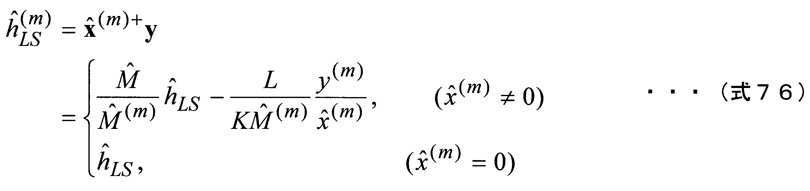
上式76では、外部シンボルレプリカを用いた場合には、第2の実施形態で用いたチャネル推定値から第mOFDMシンボルにおけるデータ信号から得られるチャネル推定値を減算すればよいことが示されている。また第mOFDMシンボルのチャネル推定時のβ(m)の値は次式77で表わされる。

このように繰り返しチャネル推定において、外部シンボルレプリカを用いることにより、当該OFDMにおけるチャネル推定値に前回のチャネル推定による影響が蓄積されないため、ターボ原理に基づいた、適切な繰り返し処理を行うことができるようになる。この結果、繰り返しチャネル推定の精度が向上し、伝送特性を向上させることができる。またLLRの算出は式73に基づいて行われることになるため、第2の実施形態の式53と比較して指数計算が不必要となるため計算量を大幅に削減できる。
上述の各実施形態およびその変形例に関わる基地局装置および端末装置で動作するプログラムは、上述の各実施形態およびその変形例における基地局装置および端末装置の機能を実現するように、CPU等を制御するプログラム(コンピュータを機能させるプログラム)である。そして、これら装置で取り扱われる情報は、その処理時に一時的にRAMに蓄積され、その後、各種ROMやHDDに格納され、必要に応じてCPUによって読み出し、修正・書き込みが行なわれる。プログラムを格納する記録媒体としては、半導体媒体(例えば、ROM、不揮発性メモリカード等)、光記録媒体(例えば、DVD、MO、MD、CD、BD等)、磁気記録媒体(例えば、磁気テープ、フレキシブルディスク等)等のいずれであってもよい。また、ロードしたプログラムを実行することにより、上述した実施形態の機能が実現されるだけでなく、そのプログラムの指示に基づき、オペレーティングシステムあるいは他のアプリケーションプログラム等と共同して処理することにより、本発明の機能が実現される場合もある。
また市場に流通させる場合には、可搬型の記録媒体にプログラムを格納して流通させたり、インターネット等のネットワークを介して接続されたサーバコンピュータに転送したりすることができる。この場合、サーバコンピュータの記憶装置も本発明に含まれる。また、上述した実施形態における基地局装置および端末装置の一部、又は全部を典型的には集積回路であるLSIとして実現してもよい。基地局装置および端末装置の各機能ブロックは個別にチップ化してもよいし、一部、又は全部を集積してチップ化してもよい。また、集積回路化の手法はLSIに限らず専用回路、又は汎用プロセッサで実現してもよい。
各機能ブロックを集積回路化した場合に、それらを制御する集積回路制御部が付加される。
各機能ブロックを集積回路化した場合に、それらを制御する集積回路制御部が付加される。
また、集積回路化の手法はLSIに限らず専用回路、又は汎用プロセッサで実現してもよい。また、半導体技術の進歩によりLSIに代替する集積回路化の技術が出現した場合、当該技術による集積回路を用いることも可能である。
また、本願発明は上述の実施形態に限定されるものではない。本願発明の端末装置は、移動局装置への適用に限定されるものではなく、屋内外に設置される据え置き型、又は非可動型の電子機器、たとえば、AV機器、キッチン機器、掃除・洗濯機器、空調機器、オフィス機器、自動販売機、その他生活機器などに適用出来ることは言うまでもない。
以上、この発明の実施形態に関して図面を参照して詳述してきたが、具体的な構成はこの実施形態に限られるものではなく、この発明の要旨を逸脱しない範囲の設計変更等も含まれる。また、本発明は、請求項に示した範囲で種々の変更が可能であり、異なる実施形態にそれぞれ開示された技術的手段を適宜組み合わせて得られる実施形態についても本発明の技術的範囲に含まれる。また、上記各実施形態に記載された要素であり、同様の効果を奏する要素同士を置換した構成も含まれる。
(1)本発明の一態様は、ビット列を表す信号を受信する受信部と、前記信号が受ける伝搬路変動を推定し、該伝搬路変動を表すチャネル推定値を算出するチャネル推定部と、前記チャネル推定値を用いて前記信号を復調し、前記ビット列に含まれるビット各々を復元する復調部とを具備し、前記復調部は、前記チャネル推定値に含まれる誤差の大きさを表す値を用いて、前記信号の復調を行う受信装置である。
(2)また、本発明の他の態様は、(1)に記載の受信装置であって、前記復調部は、前記信号と前記誤差の大きさを表す値とを少なくとも用いて表される2つの独立したガウス変数各々の確率密度関数であって、それらの積が前記信号の確率密度関数となる確率密度関数を用いて、前記復調を行う。
(3)また、本発明の他の態様は、(1)または(2)に記載の受信装置であって、前記信号の受信電力に応じた状態遷移確率を用いて、前記復調部が復元したビットに対して、誤り訂正復号する復号部を具備する。
(4)また、本発明の他の態様は、(1)から(3)のいずれかに記載の受信装置であって、前記復調部が復元したビットを、誤り訂正復号する復号部と、前記誤り訂正復号されたビットを用いて、送信シンボルのレプリカを生成するレプリカ生成部とを具備し、前記チャネル推定部によるチャネル推定と、前記復調部による復調と、前記復号部による誤り訂正復号と、前記レプリカ生成部によるレプリカの生成とを繰り返し行い、前記チャネル推定部は、前記繰り返しの2回目以降において、前記レプリカ生成が生成したレプリカを用いてチャネル推定を行う。
(5)また、本発明の他の態様は、(1)から(4)のいずれかに記載の受信装置であって、前記チャネル推定部は、前記受信した信号に含まれる受信シンボル毎に、該受信シンボルを復調する際に用いるチャネル推定値を算出し、一の受信シンボルを復調する際に用いるチャネル推定値は、該一の受信シンボルの送信シンボルのレプリカを用いずにチャネル推定を行って得られた値である。
(6)また、本発明の他の態様は、ビット列を表す信号を受信する第1の過程と、前記信号が受ける伝搬路変動を推定し、該伝搬路変動を表すチャネル推定値を算出する第2の過程と、前記チャネル推定値を用いて前記信号を復調し、前記ビット列に含まれるビット各々を復元する第3の過程とを有し、前記第3の過程にて、前記チャネル推定値に含まれる誤差の大きさを表す値を用いて、前記信号の復調を行う受信方法である。
本発明の一態様は、チャネル推定値を用いた復調により得られたビットLLRに含まれる誤差を抑えることが必要な受信装置などに適用することができる。
10…通信システム、101…基地局装置、102、102a…端末装置、201…符号化部、202…インターリーブ部、203…変調部、204…参照信号生成部、205…フレーム構成部、206…IFFT部、207…CP挿入部、208…無線送信部、209…送信アンテナ、401…受信アンテナ、402…無線受信部、403…CP除去部、404…FFT部、405…データ信号抽出部、406、406a…チャネル推定部、407、407a…復調部、408…デインターリーブ部、409、409a…復号部、501…MSE設定部、502…第1の変数算出部、503…絶対値取得部、504…第2の変数算出部、505…絶対値取得部、506…絶対値取得部、507…LLR算出部、801…インターリーブ部、802…レプリカ生成部、803…レプリカ絶対値補正部、804…参照信号生成部、805…フレーム構成部
Claims (6)
- ビット列を表す信号を受信する受信部と、
前記信号が受ける伝搬路変動を推定し、該伝搬路変動を表すチャネル推定値を算出するチャネル推定部と、
前記チャネル推定値を用いて前記信号を復調し、前記ビット列に含まれるビット各々を復元する復調部と
を具備し、
前記復調部は、前記チャネル推定値に含まれる誤差の大きさを表す値を用いて、前記信号の復調を行う受信装置。 - 前記復調部は、前記信号と前記誤差の大きさを表す値とを少なくとも用いて表される2つの独立したガウス変数各々の確率密度関数であって、それらの積が前記信号の確率密度関数となる確率密度関数を用いて、前記復調を行う請求項1に記載の受信装置。
- 前記信号の受信電力に応じた状態遷移確率を用いて、前記復調部が復元したビットに対して、誤り訂正復号する復号部を具備する請求項1に記載の受信装置。
- 前記復調部が復元したビットを、誤り訂正復号する復号部と、
前記誤り訂正復号されたビットを用いて、送信シンボルのレプリカを生成するレプリカ生成部と
を具備し、
前記チャネル推定部によるチャネル推定と、前記復調部による復調と、前記復号部による誤り訂正復号と、前記レプリカ生成部によるレプリカの生成とを繰り返し行い、
前記チャネル推定部は、前記繰り返しの2回目以降において、前記レプリカ生成が生成したレプリカを用いてチャネル推定を行う請求項1に記載の受信装置。 - 前記チャネル推定部は、前記受信した信号に含まれる受信シンボル毎に、該受信シンボルを復調する際に用いるチャネル推定値を算出し、一の受信シンボルを復調する際に用いるチャネル推定値は、該一の受信シンボルの送信シンボルのレプリカを用いずにチャネル推定を行って得られた値である請求項1に記載の受信装置。
- ビット列を表す信号を受信する第1の過程と、
前記信号が受ける伝搬路変動を推定し、該伝搬路変動を表すチャネル推定値を算出する第2の過程と、
前記チャネル推定値を用いて前記信号を復調し、前記ビット列に含まれるビット各々を復元する第3の過程と
を有し、
前記第3の過程にて、前記チャネル推定値に含まれる誤差の大きさを表す値を用いて、前記信号の復調を行う受信方法。
Priority Applications (1)
| Application Number | Priority Date | Filing Date | Title |
|---|---|---|---|
| US14/771,878 US20160013952A1 (en) | 2013-03-04 | 2014-02-19 | Reception device and reception method |
Applications Claiming Priority (2)
| Application Number | Priority Date | Filing Date | Title |
|---|---|---|---|
| JP2013-042405 | 2013-03-04 | ||
| JP2013042405 | 2013-03-04 |
Publications (1)
| Publication Number | Publication Date |
|---|---|
| WO2014136578A1 true WO2014136578A1 (ja) | 2014-09-12 |
Family
ID=51491100
Family Applications (1)
| Application Number | Title | Priority Date | Filing Date |
|---|---|---|---|
| PCT/JP2014/053907 Ceased WO2014136578A1 (ja) | 2013-03-04 | 2014-02-19 | 受信装置および受信方法 |
Country Status (2)
| Country | Link |
|---|---|
| US (1) | US20160013952A1 (ja) |
| WO (1) | WO2014136578A1 (ja) |
Cited By (2)
| Publication number | Priority date | Publication date | Assignee | Title |
|---|---|---|---|---|
| WO2017175754A1 (ja) * | 2016-04-06 | 2017-10-12 | 日本電信電話株式会社 | 無線通信システム及び通信方法 |
| CN109150389A (zh) * | 2017-06-19 | 2019-01-04 | 三星电子株式会社 | 无线通信系统中的数据解码方法和设备 |
Families Citing this family (4)
| Publication number | Priority date | Publication date | Assignee | Title |
|---|---|---|---|---|
| CN109560892B (zh) * | 2013-12-27 | 2021-04-30 | 松下电器(美国)知识产权公司 | 发送方法、接收方法及发送装置、接收装置 |
| SG11201706500SA (en) * | 2015-02-26 | 2017-09-28 | Basf Se | Method for producing isosorbide dimethacrylate |
| US10142145B2 (en) * | 2015-11-27 | 2018-11-27 | Cohda Wireless Pty Ltd. | Wireless receiver |
| US11799620B2 (en) * | 2020-04-27 | 2023-10-24 | Qualcomm Incorporated | Boosted noncoherent modulation |
Citations (2)
| Publication number | Priority date | Publication date | Assignee | Title |
|---|---|---|---|---|
| JP2007336532A (ja) * | 2006-05-19 | 2007-12-27 | Matsushita Electric Ind Co Ltd | 無線通信装置及び無線通信方法 |
| JP2008516563A (ja) * | 2004-10-12 | 2008-05-15 | クゥアルコム・インコーポレイテッド | 通信システムに適用される装置及び方法 |
Family Cites Families (1)
| Publication number | Priority date | Publication date | Assignee | Title |
|---|---|---|---|---|
| JP5428788B2 (ja) * | 2009-11-13 | 2014-02-26 | シャープ株式会社 | 受信装置、受信方法、及び受信プログラム |
-
2014
- 2014-02-19 WO PCT/JP2014/053907 patent/WO2014136578A1/ja not_active Ceased
- 2014-02-19 US US14/771,878 patent/US20160013952A1/en not_active Abandoned
Patent Citations (2)
| Publication number | Priority date | Publication date | Assignee | Title |
|---|---|---|---|---|
| JP2008516563A (ja) * | 2004-10-12 | 2008-05-15 | クゥアルコム・インコーポレイテッド | 通信システムに適用される装置及び方法 |
| JP2007336532A (ja) * | 2006-05-19 | 2007-12-27 | Matsushita Electric Ind Co Ltd | 無線通信装置及び無線通信方法 |
Non-Patent Citations (2)
| Title |
|---|
| H. SASAKI ET AL.: "Extrinsic LLR of Soft- Demapper under Presence of Channel Estimation Errors", 2013 IEEE 78TH VEHICULAR TECHNOLOGY CONFERENCE (VTC FALL, September 2013 (2013-09-01), pages 1 - 5, XP032548586, DOI: doi:10.1109/VTCFall.2013.6692205 * |
| M. NICOLI ET AL.: "Soft-Iterative Channel Estimation: Methods and Performance Analysis", IEEE TRANSACTIONS ON SIGNAL PROCESSING, vol. 55, no. 6 PART, June 2007 (2007-06-01), pages 2993 - 3006, XP011181964, DOI: doi:10.1109/TSP.2007.893979 * |
Cited By (4)
| Publication number | Priority date | Publication date | Assignee | Title |
|---|---|---|---|---|
| WO2017175754A1 (ja) * | 2016-04-06 | 2017-10-12 | 日本電信電話株式会社 | 無線通信システム及び通信方法 |
| JPWO2017175754A1 (ja) * | 2016-04-06 | 2018-08-16 | 日本電信電話株式会社 | 無線通信システム及び通信方法 |
| US10404501B2 (en) | 2016-04-06 | 2019-09-03 | Nippon Telegraph And Telephone Corporation | Wireless communication system and communication method |
| CN109150389A (zh) * | 2017-06-19 | 2019-01-04 | 三星电子株式会社 | 无线通信系统中的数据解码方法和设备 |
Also Published As
| Publication number | Publication date |
|---|---|
| US20160013952A1 (en) | 2016-01-14 |
Similar Documents
| Publication | Publication Date | Title |
|---|---|---|
| US9049063B2 (en) | Method and system for communication in a wireless network | |
| US7701917B2 (en) | Channel estimation for a wireless communication system with multiple parallel data streams | |
| US8325588B2 (en) | Iterative reception method and iterative receiver | |
| JP5356073B2 (ja) | 符号化装置、受信装置、無線通信システム、パンクチャパターン選択方法及びそのプログラム | |
| US20080273630A1 (en) | Decoding symbols of a signal distributed according to frequency and time dimensions | |
| US8824605B2 (en) | Receiving device, receiving method, receiving program, and processor | |
| WO2014136578A1 (ja) | 受信装置および受信方法 | |
| KR100932456B1 (ko) | 직교주파수분할다중접속 시스템의 셀간 간섭 완화 장치 및방법 | |
| JP2006067070A (ja) | Mimoシステム受信方法及びその装置 | |
| EP4049422A1 (en) | Method of receiving a transmitted signal over a time-varying channel and receiver thereof | |
| US20090041165A1 (en) | Receiver apparatus | |
| US9179442B2 (en) | Wireless communication system, communication apparatus, communication method, and communication program | |
| JP5641816B2 (ja) | 受信装置及び受信方法 | |
| US9166841B2 (en) | Receiving apparatus and receiving method | |
| US20100183100A1 (en) | Receiver and reception method | |
| US20100067609A1 (en) | System, transmitting apparatus and receiving apparatus for cancelling co-channel interferences and method thereof | |
| JP5833945B2 (ja) | 受信装置及びプログラム | |
| Rave et al. | Iterative correction and decoding of OFDM signals affected by clipping | |
| JP2014116644A (ja) | 受信装置 | |
| Namboodiri et al. | Low-complexity iterative receiver design for mobile OFDM systems | |
| JP5865083B2 (ja) | 受信装置及びプログラム | |
| WO2012147474A1 (ja) | 受信装置、無線通信システム、受信装置の制御プログラムおよび集積回路 | |
| Namboodiri et al. | Low complexity turbo equalization for mobile OFDM systems with application to DVB-H | |
| Chtourou et al. | Efficient doubly-iterative frequency domain turbo-equalization for single-carrier transmission over MIMO ISI channel | |
| Masuda et al. | A theoretical study on iterative detection of pre-coded OFDM |
Legal Events
| Date | Code | Title | Description |
|---|---|---|---|
| 121 | Ep: the epo has been informed by wipo that ep was designated in this application |
Ref document number: 14760609 Country of ref document: EP Kind code of ref document: A1 |
|
| WWE | Wipo information: entry into national phase |
Ref document number: 14771878 Country of ref document: US |
|
| NENP | Non-entry into the national phase |
Ref country code: DE |
|
| 122 | Ep: pct application non-entry in european phase |
Ref document number: 14760609 Country of ref document: EP Kind code of ref document: A1 |
|
| NENP | Non-entry into the national phase |
Ref country code: JP |