WO2014136451A1 - 情報共有方法 - Google Patents
情報共有方法 Download PDFInfo
- Publication number
- WO2014136451A1 WO2014136451A1 PCT/JP2014/001224 JP2014001224W WO2014136451A1 WO 2014136451 A1 WO2014136451 A1 WO 2014136451A1 JP 2014001224 W JP2014001224 W JP 2014001224W WO 2014136451 A1 WO2014136451 A1 WO 2014136451A1
- Authority
- WO
- WIPO (PCT)
- Prior art keywords
- information
- home appliance
- home
- type
- display
- Prior art date
- Legal status (The legal status is an assumption and is not a legal conclusion. Google has not performed a legal analysis and makes no representation as to the accuracy of the status listed.)
- Ceased
Links
Images




























Classifications
-
- H—ELECTRICITY
- H04—ELECTRIC COMMUNICATION TECHNIQUE
- H04L—TRANSMISSION OF DIGITAL INFORMATION, e.g. TELEGRAPHIC COMMUNICATION
- H04L41/00—Arrangements for maintenance, administration or management of data switching networks, e.g. of packet switching networks
- H04L41/22—Arrangements for maintenance, administration or management of data switching networks, e.g. of packet switching networks comprising specially adapted graphical user interfaces [GUI]
-
- G—PHYSICS
- G06—COMPUTING OR CALCULATING; COUNTING
- G06Q—INFORMATION AND COMMUNICATION TECHNOLOGY [ICT] SPECIALLY ADAPTED FOR ADMINISTRATIVE, COMMERCIAL, FINANCIAL, MANAGERIAL OR SUPERVISORY PURPOSES; SYSTEMS OR METHODS SPECIALLY ADAPTED FOR ADMINISTRATIVE, COMMERCIAL, FINANCIAL, MANAGERIAL OR SUPERVISORY PURPOSES, NOT OTHERWISE PROVIDED FOR
- G06Q10/00—Administration; Management
- G06Q10/10—Office automation; Time management
-
- G—PHYSICS
- G05—CONTROLLING; REGULATING
- G05B—CONTROL OR REGULATING SYSTEMS IN GENERAL; FUNCTIONAL ELEMENTS OF SUCH SYSTEMS; MONITORING OR TESTING ARRANGEMENTS FOR SUCH SYSTEMS OR ELEMENTS
- G05B15/00—Systems controlled by a computer
- G05B15/02—Systems controlled by a computer electric
-
- G—PHYSICS
- G06—COMPUTING OR CALCULATING; COUNTING
- G06Q—INFORMATION AND COMMUNICATION TECHNOLOGY [ICT] SPECIALLY ADAPTED FOR ADMINISTRATIVE, COMMERCIAL, FINANCIAL, MANAGERIAL OR SUPERVISORY PURPOSES; SYSTEMS OR METHODS SPECIALLY ADAPTED FOR ADMINISTRATIVE, COMMERCIAL, FINANCIAL, MANAGERIAL OR SUPERVISORY PURPOSES, NOT OTHERWISE PROVIDED FOR
- G06Q10/00—Administration; Management
- G06Q10/40—Business processes related to social networking or social networking services
-
- G—PHYSICS
- G06—COMPUTING OR CALCULATING; COUNTING
- G06Q—INFORMATION AND COMMUNICATION TECHNOLOGY [ICT] SPECIALLY ADAPTED FOR ADMINISTRATIVE, COMMERCIAL, FINANCIAL, MANAGERIAL OR SUPERVISORY PURPOSES; SYSTEMS OR METHODS SPECIALLY ADAPTED FOR ADMINISTRATIVE, COMMERCIAL, FINANCIAL, MANAGERIAL OR SUPERVISORY PURPOSES, NOT OTHERWISE PROVIDED FOR
- G06Q10/00—Administration; Management
- G06Q10/40—Business processes related to social networking or social networking services
- G06Q10/42—Determination of affinities or common interests between users
-
- G—PHYSICS
- G05—CONTROLLING; REGULATING
- G05B—CONTROL OR REGULATING SYSTEMS IN GENERAL; FUNCTIONAL ELEMENTS OF SUCH SYSTEMS; MONITORING OR TESTING ARRANGEMENTS FOR SUCH SYSTEMS OR ELEMENTS
- G05B2219/00—Program-control systems
- G05B2219/20—Pc systems
- G05B2219/26—Pc applications
- G05B2219/2613—Household appliance in general
Definitions
- the present invention relates to an information sharing method for realizing an information sharing service using information obtained from home appliances (home appliances and sensors).
- SNS social network services
- the current information on the SNS is mainly text information input by the service user, and the occurrence time of the event targeted by the information is unknown.
- Patent Document 1 there is a method disclosed in Patent Document 1 as an example of a method of sharing the operation status of a device with another person.
- a portable terminal performs remote control of a device installed in a building, and information controlled at that time is notified to other users by e-mail.
- An object of the present invention is to provide a more attractive graphical user interface image in which the reality and real-time characteristics of information are enhanced by sharing information on changes in the state of devices that actually occurred by a plurality of users. .
- An information sharing method for providing a graphical user interface image for a plurality of users to share information on a device in a home, comprising: According to the receiving step of receiving information as home appliance event information, the priority determining step of determining the home priority to be displayed according to the occurrence frequency of each home of the home appliance event information, and according to the priority Determining a home to display on the graphical user interface image.
- the above information sharing method provides a more attractive graphical user interface image in which the reality and real-time nature of information are enhanced by sharing information on the device state change that has actually occurred by a plurality of users. be able to.
- the figure which shows the structure of the information sharing system of Embodiment 1 of this invention A configuration diagram of the information sharing system showing the inside of the house in FIG. 1 in more detail Flowchart showing the operation of the information sharing system according to the first embodiment of the present invention
- a schematic diagram for explaining the occurrence frequency of housework events used in the information sharing system according to the first embodiment of the present invention The figure which shows an example of the setting information of the transmitting side user used for the character setting of the house used for the information sharing system of Embodiment 1 of this invention.
- a diagram showing an example of effect of character setting of a house used in the information sharing system according to the first embodiment of the present invention A diagram showing an example of the configuration of the server and DB shown in FIG. 1 in detail Flowchart showing an example of message superposition processing of the information sharing system according to Embodiment 1 of the present invention
- a flowchart showing an example of processing when displaying a GUI on the display device shown in FIG. A flowchart showing an example of processing when the display content of the GUI is determined based on the information of the sensor log server shown in FIG.
- a flowchart showing an example of processing when the display content of the GUI is determined based on the information of the SNS server shown in FIG. 13 A flowchart showing an example of processing when the display content of the GUI is changed based on the information of the sensor shown in FIG. 13
- a flowchart showing an example of processing when the display content of the GUI is changed based on the information of the SNS server shown in FIG. 13 A flowchart showing an example of processing when the SNS server shown in FIG.
- FIG. 13 receives information from the SNS event processing module A flowchart showing an example of processing when the display device shown in FIG. 13 updates the display content of the GUI
- FIG. The first figure showing an example of change of GUI at the time of reception of household appliance event information
- the 2nd figure which shows the example of change of GUI at the time of reception of household appliance event information
- the 3rd figure which shows the example of change of GUI at the time of reception of household appliance event information
- the 4th figure which shows the example of change of GUI at the time of reception of household appliance event information The figure which shows an example of the screen transition of GUI displayed on the display apparatus shown in FIG.
- a diagram showing an example of an internal configuration of the GW shown in FIG. A flowchart showing an example of processing when a new home appliance or sensor of GW shown in FIG. 30 is found A flowchart showing an example of processing when a new home appliance or sensor of the display device shown in FIG. 30 is found
- a diagram showing an example of home appliance event information used to determine the type of device connected to the network A diagram showing an example of home appliance event information acquired from the home appliance management server shown in FIG.
- FIG. 3 The figure which shows an example of GUI in Embodiment 3 of this invention
- FIG. 38 The figure which shows the structure of the information sharing system of Embodiment 4 of this invention.
- a diagram showing an example of a configuration of a server shown in FIG. A diagram showing an example of a customer database stored in a customer DB shown in FIG. 38 and an example of a user operation history database stored in an operation history DB
- a diagram showing an example of a community database stored in the community DB shown in FIG. 38 A flowchart showing an example of control processing of the server shown in FIG.
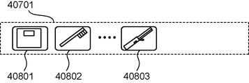
- a diagram showing a display example of connected devices in the device area shown in FIG. A diagram showing a display example of measurement data in the log area shown in FIG.
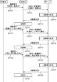
- FIG. 37 is a sequence diagram showing an example of control processing using the wash basin and weight scale of the server shown in FIG.
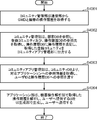
- the figure which shows an example of the display screen displayed on the display apparatus shown in FIG. A flowchart showing an example of processing in the information sharing system shown in FIG.
- Flowchart showing the first extension processing in the information sharing system shown in FIG. A diagram showing another example of a display screen displayed on the display device shown in FIG.
- FIG. 47 is a flowchart showing a second extension process in the information sharing system shown in FIG.
- FIG. 54 A diagram showing an example of a display screen displayed on the display device shown in FIG. 54.
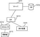
- a flowchart showing an example of processing in the information sharing system shown in FIG. 54 The figure which shows the structure of the information sharing system of Embodiment 6 of this invention.
- the figure which shows an example of the display screen displayed on the display apparatus shown in FIG. A flowchart showing an example of processing in the information sharing system shown in FIG. FIG. 57 is a flowchart showing a first extension process in the information sharing system shown in FIG. 57.
- the figure which shows another example of the display screen displayed on the display apparatus shown in FIG. FIG. 57 is a flowchart showing a second extension process in the information sharing system shown in FIG. 57.
- Embodiment 1 In the present embodiment, for example, an information display screen for collecting, as home appliance event information, information on state changes of appliances such as home appliances and sensors in the home that occur due to user operation and the like ( A method of forming a graphical user interface image) will be described.
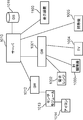
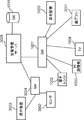
- FIG. 1 is a diagram showing the configuration of an information sharing system according to a first embodiment of the present invention.
- home appliances 101 and 102 in homes 110, 111 and 112 registered in advance with respect to server 1010 are home appliances via gateway (hereinafter referred to as “GW”) 103.
- GW gateway
- Household appliance event information including the state of the device is transmitted.
- each of the houses 110, 111, 112 represents one home.
- the server 1010 acquires home appliance event information of the home appliances 101 and 102 sent from the homes 110, 111, and 112, and stores the acquired home appliance event information in the DB (database) 1011.
- the server 1010 extracts home appliance event information of a house (home) desired by the user from the DB 1011 based on setting information of the user who owns the display device 104, and the home appliance type and housework type included in the home appliance event information Information on each house is formed as screen information based on the occurrence frequency of home appliance event information, and screen information (graphical user interface image) is provided in response to a request from the display device 104.
- the information sharing system shown in FIG. 1 is an information sharing system for providing a graphical user interface image for sharing information on home appliances by a plurality of users
- the server 1010 includes a plurality of homes 110 and 111
- Information of the state change of the home appliance 101, 102 in 112 is received as home appliance event information, and according to the occurrence frequency in each home 110, 111, 112 of the home appliance event information, of the house to be displayed on the graphical user interface image
- the priority is determined, and according to the determined priority, a house to be displayed on the graphical user interface image is determined.
- the home appliance event information also includes home appliance type information indicating the type of the device.
- the server 1010 classifies the home appliance event information for each device type using the home appliance type information, and indicates the priority of the house to be displayed on the graphical user interface image according to the occurrence frequency of the home appliance event information for each device type. Are determined, and according to the determined priority, the house to be displayed in the graphical user interface image is determined.
- the server 1010 generates and displays a graphical user interface image in which the display state of the device icon representing the in-home device to be displayed in the graphical user interface image is changed according to the occurrence frequency of home appliance event information for each device type.
- the display device 104 changes the display state of the device icon according to the occurrence frequency of the home appliance event information for each type of device, and displays it on the graphical user interface image.
- the home appliance event information also includes home appliance type information indicating the type of the device, and housework type information indicating the type of housework associated with the type of the device identified by the home appliance type information.
- the server 1010 classifies household appliance event information by household category using household category information, and gives priority to a house to be displayed according to the occurrence frequency of household appliance event information associated with the household category selected by the user. The degree is determined, and according to the determined priority, the house to be displayed in the graphical user interface image is determined.
- the server 1010 also displays a graphical user interface image in which the display state of a home icon representing a house to be displayed in the graphical user interface image is changed according to the occurrence frequency of home appliance event information associated with the type of household chores selected by the user. It generates and transmits to the display device 104.
- the display device 104 changes the display state of the home icon according to the occurrence frequency of the home appliance event information associated with the type of housework selected by the user, and displays the home icon on the graphical user interface image.
- the server 1010 receives message information including request information requesting display linked to the type of device selected by the user or the type of housework, and a message input by the user, and the device specified by the request information
- message information including request information requesting display linked to the type of device selected by the user or the type of housework, and a message input by the user, and the device specified by the request information
- a graphical user interface image in which a message is superimposed and generated is generated and transmitted to the display device 104.
- the display device 104 superimposes and displays a message on the graphical user interface image when the server 1010 receives home appliance event information associated with the type of device specified by the request information or the type of housework.
- the server 1010 generates a graphical user interface image in which message information is superimposed and displayed near the home icon of the user who has transmitted the message information, and transmits the image to the display device 104.
- the display device 104 displays a home icon on a graphical user interface image and superimposes and displays message information in the vicinity of the home icon.
- the server 1010 generates a graphical user interface image in which message information is superimposed and displayed in the vicinity of the device icon representing the device of the user who has sent the message information and transmits the message to the display device 104.
- the display device 104 displays the device icon on the graphical user interface image and superimposes and displays the message information in the vicinity of the device icon.
- the display device 104, the home appliances 101 and 102, and the sensor do not necessarily need to communicate with the server 1010 via the GW, and may include communication means for direct communication with the server 1010.
- the GW may be an access point of a wireless local area network (LAN), or may be a dedicated GW which is connected to each device by power saving radio or the like and further connected to the server 1010 via the Internet.
- the display device 104 may be any device capable of displaying screen information such as a television, a smartphone, a PC (personal computer) or the like, and may be a home appliance as long as the screen information can be displayed.
- FIG. 2 is a block diagram of the information sharing system showing the inside of the house 110 in FIG. 1 in more detail.
- a microwave oven 1002 As illustrated in FIG. 2, as the home appliances 101 and 102 illustrated in FIG. 1, a microwave oven 1002, an induction heating (IH) cooker 1003, and a TV (television) 1004 are connected to the GW 1001.
- IH induction heating
- TV television
- the device targeted by the present invention is not only a home appliance, a sensor, a home appliance incorporating a sensor, but may be a home appliance having a sensor module attached thereto, and a sensor module for an object such as a rattan By attaching an object, an object such as a bag can be treated as a home appliance.
- the home appliance and the display device may access the server 1010 by access to the Internet network such as a 3G (Third-Generation) line directly like the vacuum cleaner 1005 and the display device 1100.
- the server 1010 is often mainly deployed on the cloud.
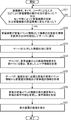
- FIG. 3 is a flowchart showing the operation of the information sharing system according to the first embodiment of the present invention.
- each of the home appliances 101 and 102 determines whether the operation status of the home appliance has changed due to remote control, a timer, an input by the user, or the like, or by a sensor (for example, sensor module 1013) It is determined whether the state of the appliance has changed by determining whether the state of the home appliance 101 or 102 or the environment around the home appliance 101 or 102 has changed (step S31).
- step S31 If there is a change in the operation status of the home appliance (YES in step S31), the home appliances 101 and 102 notify the server 1010 of the information on the status change of the home appliance directly or via the GW 103 as home appliance event information (Step S32). On the other hand, when there is no change in the operation status of the home appliance (NO in step S31), the process in step S31 is repeated.
- the server 1010 stores the acquired home appliance event information in the DB 1011 (step S33).
- the server 1010 receives a screen information request from the display device 104, the information of the user requested by the screen information request (for example, the display-set house, house category preference, registered community, browsing Information etc.) is acquired from the DB 1011 (step S34).
- the server 1010 acquires home appliance type information and housework type information from home appliance event information for each home necessary for screen formation (step S35).
- the server 1010 changes the display content of each house from the generation frequency of home appliance event information for each house, the generation frequency of home appliance event information for each housework type, the generation frequency of home appliance event information for each household appliance type, and user information To form a display screen, and the display screen is transmitted to the display device 104 (step S36).
- the server 1010 generates a graphical user interface image according to the occurrence frequency of home appliance event information for each house, the occurrence frequency of home appliance event information for each household type, and the occurrence frequency of home appliance event information for each home appliance type. Determine the priority of the house to be displayed. Based on the determined priority, the server 1010 determines a house having a predetermined number of upper priorities (for example, the top five houses) as a house to be displayed on the graphical user interface image, and a home icon representing the determined house , Etc. are generated and transmitted to the display device 104.
- a predetermined number of upper priorities for example, the top five houses
- the display device 104 displays the received display screen (graphical user interface image) (step S37).
- FIG. 4 is a diagram showing an example of screen information of an information sharing service by the information sharing system according to the first embodiment of the present invention.
- the screen information shown in FIG. 4 is displayed as a graphical user interface image on the display device 104 of the user, and the operation state information of the home appliances of each house that the user wants to view is displayed and shared on the screen.
- the priority of the house to be displayed in the graphical user interface image is determined, and three high priority houses among the transmitting users are determined.
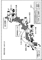
- home icons 1202, 1204, and 1205 corresponding to the three homes of the transmitting user are displayed on the map of Japan, in addition to the home icons 1201 corresponding to the homes of the browsing user.
- the air conditioner which is a heating device when the air conditioner which is a heating device is heating up at maximum and the users of the community like the condition of the air conditioning, use the heating device without displaying other houses. Select the house you are using and display it. In this case, for example, set an area divided into six blocks etc. on the map of Japan, and set one to select and display a house where the use of air conditioning is remarkable for each area, and a cleaning event While displaying a large number of homes, it is also possible to display information on homes that are prominently used for air conditioning.
- the user can input a message in this service and can display the information in accordance with the home appliance event.
- voice data may be input using a voice input device
- moving images may be shared using a moving image input device.
- voice recognition device it is also possible to convert voice data into text and display it using a voice recognition device.
- which house is to be selected is selected from setting information of the transmitting user who discloses the information and setting information of the browsing user who browses the information. For example, when the transmitting side user wants to appeal cooking, when the frequency of occurrence of cooking-related home appliance event information is equal to or higher than a certain level, the priority increases in the selection of the house displayed on the display device 104 of the viewing side user. Home appliances of the family are displayed at positions that are larger or more easily visible than other home appliances.
- a house displayed on the display device 104 of the browsing user is selected based on the preference and setting information of the browsing user.
- the sending user and the viewing user are the same person, and if the sending user's setting information is information that gives priority to cooking-related housework, the viewing user's screen information is also given priority. It is possible to display information according to the degree.
- FIG. 5 is a figure which shows an example of household appliance event information used for the information sharing system of Embodiment 1 of this invention.
- the home appliance event information includes the event occurrence time of the home appliance event information, the device ID (identification information) for identifying the home appliance or sensor that is the source of the home appliance event information, the type of home appliance or sensor Home appliance type representing the household appliance type or housework type representing the type of housework to which the sensor is associated, detailed housework category that classifies the housework type in further detail, event representing the operation of the home appliance or sensor, etc. and operation of the home appliance or sensor And each information of the event value which classified the in further detail.
- the household type may be set from the household appliance type by user setting on the server 1010 side.
- the head speed of the vacuum cleaner can be obtained using an acceleration sensor, a rotary encoder, or the like.
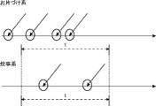
- FIG. 6 is a schematic diagram for explaining the occurrence frequency of housework events used in the information sharing system according to the first embodiment of the present invention. As shown in FIG. 6, for example, when the housework type is classified into a tidying system or a cooking system, the occurrence frequency of home appliance event information (a circle indicated by an arrow in the drawing) can be acquired for each housework type.
- the server 1010 determines the number of occurrences of home appliance event information within a predetermined unit time t (for example, three minutes) (three in the example of the cleaning system and two in the cooking system) in the example of FIG. Calculated as the occurrence frequency of home appliance event information.
- the server 1010 sets the priority of the house to be displayed and the character setting that is the display effect of the displayed house itself according to the occurrence frequency of the home appliance event information and the number of home appliances operating at the same time.
- FIG. 7 is a diagram showing an example of setting information of a transmitting user used for character setting of a house used in the information sharing system according to the first embodiment of the present invention.
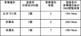
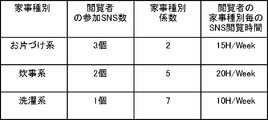
- the setting information of the transmitting side user used for setting the character of the house is the type of housework, the number of SNS in which the registrant (sending side user) participates, and a weighting factor assigned to each housework type.
- the housework type coefficient which is and each information on the browsing time of the SNS for each housework type of the registrant (sender side user) is included.
- the occurrence frequency of home appliance event information is multiplied by a household incident type coefficient, and the priority of a home (home) to be displayed is determined from the multiplication value. For example, 2 is set as the housework classification coefficient for the housework classification of the clearing system, and 5 is set as the housework classification coefficient for the housework classification of the cooking system.
- the server 1010 selects the priority of the house (home) to be displayed and the display effect by using the SNS browsing time for each type of housework of the registrant as other information.
- FIG. 8 is a diagram showing an example of setting information of a reading user used for character setting of a house used in the information sharing system according to the first embodiment of the present invention.
- the setting information of the browsing user used for setting the character of the house is the type of household chores, the number of SNSs in which the viewer (browsing user) participates, and the weighting factor assigned to each household chop
- the housework type coefficient which is and each information on the browsing time of the SNS for each housework type of the viewer (viewing side user) is included.
- the server 1010 determines the interest of the browser based on the number of participating SNSs of the browser above, determines the preferred household type according to the browsing time of the SNS for each household type, and displays the information based on the information. Choose the priority of homes (homes) and display effects.
- the housework type coefficient that is a weighting factor is set for the housework type, it is not particularly limited to this example, and a home appliance type coefficient that is a weighting factor is set for the home appliance type,
- the home appliance event information occurrence frequency may be corrected using the home appliance type coefficient.
- FIG. 9 is a diagram showing an example of effect of character setting of a house used in the information sharing system according to the first embodiment of the present invention.
- the server 1010 can generate a graphical user interface image for directing and displaying the character setting of the house as shown in FIG. 9 using the parameters of the respective information shown in FIG. 5, FIG. 7 and FIG.
- FIG. 10 is a diagram showing an example in which the configurations of the server 1010 and the DB 1011 shown in FIG. 1 are shown in detail.
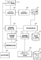
- the server 1010 shown in FIG. 1 includes another service event processing unit 131, an event information receiving unit 132, an event information storage unit 133, a screen information request accepting unit 134, a display information selection unit 135, and screen information formation.
- a DB 1011 illustrated in FIG. 1 includes an event information database D1, a display user information database D2, and a community.
- An application database D3 is provided.
- the server 1010 has an event information receiving unit 132 that receives home appliance event information, and the event information storage unit 133 stores home appliance event information in the event information database D1. Not only home appliance event information but also user setting information is stored in the event information database D1, and user ID, display housework type priority, registered community, community browsing time, message exchange frequency by house as setting information of each user Such information is accumulated, and when sorting home appliance event information, these information can be used.
- the event information receiving unit 132 instructs the screen information request receiving unit 134 to update the information when the information has already been displayed for the browsing user according to the type of home appliance event information.
- the screen information request accepting unit 134 accepts a screen display request of the browsing user.
- the display information selection unit 135 is based on the information stored in the display user information database D2 and the event information database D1, such as user ID, display housekeeping type priority, registered community, community browsing time, message exchange frequency by house, etc. Select the information to be displayed.
- the screen information update processing unit 137 performs screen information update using the information selected by the display information selection unit 135.
- the screen information formation unit 136 finally configures the screen according to the screen information update of the screen information update processing unit 137, and the screen information (graphical user) is displayed on the display device 104 of the browsing user via the screen information transmission unit 138. Interface image).
- the community application database D3 stores various community applications, and the community application processing unit 140 processes the community applications read from the community application database D3.
- the screen information update processing unit 137 executes the associated community application or the like using the community application processing unit 140 depending on the type of home appliance event information.
- the other service event processing unit 131 has an interface with a service such as another SNS, receives an event such as a message input, and operates in conjunction with the process of forming screen information. Moreover, the convenience of the user of the other service can also be achieved by notifying the other service of the home appliance event information required by the other service event processing unit 131.
- FIG. 11 is a flowchart showing an example of the message superimposing process of the information sharing system according to the first embodiment of the present invention.
- the server 1010 determines whether or not there is an input event by the transmitting side user who discloses the information (step S101).
- an event such as text or voice is transmitted from the transmitting side user disclosing information directly or in conjunction with another site (YES in step S101)
- the server 1010 transmits the information of the transmitting side user disclosing the information. Are acquired (step S102).
- the server 1010 determines whether there is message information associated with the home appliance event information (step S103).
- the message information includes request information for requesting a display interlocked with the type of device selected by the user or the type of housework, and a message input by the user.
- related event information or the like may be added to the message header, and in this case, there may be a setting icon or the like at the time of input, and a graphical user interface (GUI) may be set.
- GUI graphical user interface
- a specific keyword text, voice, etc.
- step S103 When there is message information associated with the home appliance event information (YES in step S103), the server 1010 generates home appliance event information associated with the type of the device specified by the request information of the message information or the type of the housework Occasionally, a message is superimposed according to the timing to form a screen (step S104). On the other hand, when there is no message information associated with the home appliance event information (NO in step S103), the server 1010 outputs the information as it is (step S105).
- FIG. 12 is a diagram showing an example of message information used for message superimposing processing of the information sharing system according to the first embodiment of the present invention.
- the message content is a user input text message and the IH cooker is set in the request information as the message association home appliance type
- the IH cooker starts operation Home appliance event information is sent, and in accordance with this, a message is displayed superimposed on the graphical user interface image.
- the server 1010 requests “cleansing” “requests to request a display linked to the vacuum cleaner as the type of the device selected by the user”.
- the user interface image is created, and the display device 104 superimposes and displays a message 1206 of “Good cleaning” in the vicinity of the home icon 1201.
- the server 1010 displays a display linked to the electric pot as the type of the device selected by the user.
- “hot water may be created near the device icon 1207.
- a graphical user interface image in which a message 1203 of "Let's tea” is superimposed is created, and the display device 104 superimposes a message 1203 of "Let's drink tea” in the vicinity of the device icon 1207.
- the message content is a message of preset text
- text preset in advance may be superimposed according to the operation of the fan, for example, tweet information is output when the fan is cut off. It is also good.
- the voice may be superimposed while detecting that the pot has moved (in this case, acquiring information by an acceleration sensor or the like).
- the present embodiment it is possible to collect, as home appliance event information, status change information of home appliances in the home that occurs due to user operation or the like, and form an information display screen for sharing on a social network. .
- home appliance event information that is information on changes in the state of the device that has actually occurred by a plurality of users, a more attractive graphical user whose reality and real-time property of information are enhanced An interface image can be provided.
- FIG. 13 is a diagram showing the configuration of the information sharing system according to the second embodiment of the present invention.
- the state of home appliances from the home appliance 2002 etc. in each home registered in advance to the event processing server 2005 shown in FIG. 13 is included.
- the home appliance event information is transmitted, and based on the type of home appliance event information and the occurrence frequency of the home appliance event information, the information of each house is formed as the screen information, and the screen information is provided to the request of the display device 2008
- the explanation thereof is omitted, and the features of the present embodiment will be described in detail below.
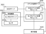
- the information sharing system illustrated in FIG. 13 includes an SNS server 2001, a home appliance 2002, an event processing server 2005, and a display device 2008.
- the event processing server 2005 includes an SNS event processing module 2006 and a sensor event processing module 2007.
- the home appliance 2002 includes a sensor log server 2003 and a sensor 2004.
- the event processing server 2005, the display device 2008, and the home appliance 2002 are connected by a home LAN, and the event processing server 2005 and the SNS server 2001 exist on the WWW (World Wide Web).
- the event processing server 2005 aggregates sensing information (home appliance event information) of home appliances 2002 connected to the network generated in each home via the sensor event processing module 2007, and displays home appliance event information as a GUI of the display device 2008. Convert to information necessary for display of (graphical user interface image) and hold it.
- sensing information may be aggregated without passing through the sensor event processing module 2007.
- the sensor log server 2003 aggregates and holds the sensor values (home appliance event information) detected by the sensor 2004, and transmits the detected sensor values to the sensor event processing module 2007 and a request from the sensor event processing module 2007. In response, transmission of the sensor value to be held is performed.
- the sensor log server 2003 may be mounted on a device different from the home appliance 2002, may exist as a single device, or may exist on the WWW.
- the sensor 2004 is mounted on the home appliance 2002, detects the operation or state of the home appliance 2002, and notifies the sensor log server 2003 of the operation. Note that the sensor 2004 may be mounted on a device other than the home appliance 2002, or may be mounted on an item such as a household product as the sensor 2004 alone.
- the event processing server 2005 includes an SNS event processing module 2006 and a sensor event processing module 2007.
- the event processing server 2005 may be mounted on the display device 2008, may exist on the WWW, or may exist as a single device.
- the SNS event processing module 2006 receives home appliance event information and the like transmitted from the SNS server 2001, and transmits home appliance event information and the like to the display device 2008. Further, the SNS event processing module 2006 requests the SNS server 2001 for necessary home appliance event information, and after receiving home appliance event information, transmits the received home appliance event information to the display device 2008. In addition, the SNS event processing module 2006 transmits home appliance event information and the like to the SNS server 2001 based on the home appliance event information transmitted from the sensor event processing module 2007.
- the sensor event processing module 2007 receives home appliance event information from the sensor log server 2003, and transmits home appliance event information to the display device 2008 and the SNS event processing module 2006 as necessary.
- the display device 2008 performs acquisition of a GUI (graphical user interface image) and update of the display content according to the home appliance event information transmitted from the SNS event processing module 2006 and the sensor event processing module 2007.
- the display device 2008 may hold a GUI to be displayed in advance.
- FIG. 14 is a flowchart showing an example of processing in the case of displaying a GUI on the display device 2008 shown in FIG. 13, and shows an example of a GUI (graphical user interface image) displayed on the display device 2008 shown in FIG. Shown in 23.
- GUI graphical user interface image
- the sensor 2004 transmits that the operation start (sensor value) to the sensor log server 2003 as home appliance event information.
- the sensor log server 2003 transmits the received home appliance event information (sensor value) to the sensor event processing module 2007 of the event processing server 2005 (step S141).
- the sensor event processing module 2007 receives home appliance event information (sensor value) from the sensor 2004 (step S142), and transmits the received home appliance event information to the display device 2008 available to the user (step S143).
- the display device 2008 receives home appliance event information from the sensor event processing module 2007 of the event processing server 2005 (step S144), and matches the received home appliance event information with the type of the display device 2008 (for example, screen size and screen resolution).
- the GUI is requested to the SNS server 2001 (step S145).
- the SNS server 2001 receives the GUI request from the display device 2008 (step S146), and transmits the requested GUI to the display device 2008 (step S147).
- the display device 2008 receives a file such as HTML (HyperText Markup Language) for displaying the GUI from the SNS server 2001 (step S148), and displays the GUI on the screen (step S149).
- HTML HyperText Markup Language
- the display device 2008 displays the GUI
- the process after step S151 in FIG. 15 or the step S161 in FIG. implement the following processing.
- the processing after step S171 of FIG. 17 described later or the processing after step S181 of FIG. 18 are performed.
- FIG. 15 is a flowchart showing an example of processing when the display contents of the GUI are determined based on the information of the sensor log server 2003 shown in FIG.
- the sensor event processing module 2007 of the event processing server 2005 is in a state of waiting for reception of home appliance event information transmitted from the display device 2008 connected to the in-home LAN (step S151).
- the sensor event processing module 2007 transmits a use state request event to the sensor log server 2003 of the home appliance 2002 (step S152).
- the sensor log server 2003 receives a request event from the sensor event processing module 2007 of the event processing server 2005 (step S153), and transmits information (usage status) corresponding to the content of the event to the sensor event processing module 2007 of the event processing server 2005 (Step S154).
- the sensor event processing module 2007 of the event processing server 2005 receives home appliance event information from the sensor log server 2003 of the home appliance 2002 (step S155), and the received home appliance event information is transmitted from the home appliance 2002 connected to the in-home LAN. It is determined whether it is the home appliance event information (step S156). If the sensor event processing module 2007 is home appliance event information of a home appliance 2002 connected to the home LAN (YES in step S156), the sensor event processing module 2007 notifies the SNS event processing module 2006 of home appliance event information, and passes through the SNS event processing module 2006 Then, sensor information (home appliance event information) is transmitted to the SNS server 2001 (step S157), and the acquired information (home appliance event information) is transmitted to the display device 2008 (step S158).
- FIG. 16 is a flowchart showing an example of processing when the display content of the GUI is determined based on the information of the SNS server 2001 shown in FIG.
- the SNS event processing module 2006 of the event processing server 2005 is in a state of waiting for reception of home appliance event information transmitted from the sensor log server 2003 and the display device 2008 on the WWW (step S161).
- the SNS event processing module 2006 transmits a request event of the other house status to the SNS server 2001 on the WWW (step S162).
- the SNS server 2001 receives the request event from the SNS event processing module 2006 of the event processing server 2005 (step S163), and the home appliance event information (other home status) according to the event content is sent to the SNS event processing module 2006 of the event processing server 2005 It transmits to (step S164).
- the SNS event processing module 2006 of the event processing server 2005 receives home appliance event information from the SNS server 2001 on the WWW (step S165), and the home appliance event in which the received home appliance event information is transmitted from the SNS server 2001 on the WWW It is determined whether it is information (step S166). If the SNS event processing module 2006 is home appliance event information transmitted from the SNS server 2001 on the WWW (YES in step S166), the acquired information (sent from the SNS server 2001 on the WWW) to the display device 2008 The home appliance event information is transmitted, and the display device 2008 receives home appliance event information from the SNS server 2001 on the WWW (step S167).
- FIG. 17 is a flowchart showing an example of processing when the display content of the GUI is changed based on the information of the sensor 2004 shown in FIG.
- the sensor event processing module 2007 of the event processing server 2005 is in a state of waiting for reception of home appliance event information transmitted from the sensor log server 2003 connected to the in-home LAN (step S171).
- the sensor event processing module 2007 detects the sensor log server 2003 of the home appliance 2002.
- the home appliance event information is received from the home appliance (step S173), and it is determined whether the home appliance event information is transmitted from the home appliance 2002 connected to the home LAN (step S174).
- the sensor event processing module 2007 is home appliance event information of a home appliance 2002 connected to the in-home LAN (YES in step S 174)
- the sensor event processing module 2007 notifies the SNS event processing module 2006 of the information, and the SNS via the SNS event processing module 2006
- the sensor information home appliance event information
- the server 2001 step S175
- the acquired information home appliance event information
- FIG. 18 is a flowchart showing an example of processing when the display content of the GUI is changed based on the information of the SNS server 2001 shown in FIG.
- the SNS event processing module 2006 of the event processing server 2005 is in a state of waiting for reception of home appliance event information transmitted from the SNS server 2001 and the display device 2008 on the WWW (step S181).
- the SNS event processing module 2006 receives home appliance event information from the SNS server 2001 on the WWW (step S182). ), It is determined whether it is home appliance event information transmitted from the SNS server 2001 on the WWW (step S183).
- the SNS event processing module 2006 is home appliance event information transmitted from the SNS server 2001 on the WWW (YES in step S183), the information acquired to the display apparatus 2008 (sent from the SNS server 2001 on the WWW) The home appliance event information is transmitted (step S184).
- FIG. 19 is a flowchart showing an example of processing when the SNS server 2001 shown in FIG. 13 receives information from the SNS event processing module 2006.
- the SNS server 2001 receives home appliance event information of the home appliance 2002 of each home from the SNS event processing module 2006 of the event processing server 2005 (step S191).
- the SNS server 2001 determines whether there is an event processing server 2005 waiting to receive home appliance event information from the SNS server 2001 (step S192).
- step S 192 If there is an event processing server 2005 waiting for reception of home appliance event information from the SNS server 2001 (YES in step S 192), the SNS server 2001 is installed in the home appliance 2002 in each home in the received home appliance event information
- the received home appliance event information is analyzed by processing and analyzing the information of the sensor 2004 and the user operation information on the GUI displayed on the display device 2008, and the processing process is performed (step S193), and the event processing Home appliance event information is transmitted to the server 2005 (step S194).
- the home appliance event information received from the SNS event processing module 2006 includes information on the sensor 2004 mounted on the home appliance 2002 in each home and user operation information on the GUI displayed on the display device 2008. These pieces of information are accumulated in the SNS server 2001 and analyzed as information accumulated from a plurality of homes, or used to change the display contents of the GUI displayed on the display device 2008 of each home.
- FIG. 20 is a flowchart showing an example of processing when the display device 2008 shown in FIG. 13 receives home appliance event information related to display content change of the GUI from the SNS event processing module 2006 or the sensor event processing module 2007.
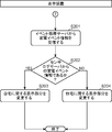
- the display device 2008 receives home appliance event information from the SNS event processing module 2006 or the sensor event processing module 2007 of the event processing server 2005 (step S201), and the received home appliance event information is home appliance event information from the sensor log server 2003 It is determined whether it is home appliance event information from the SNS server 2001 (NO in step S202).
- the display device 2008 changes the display part related to the home (step S203), and if the home appliance event information from the SNS server 2001 changes the display part related to the other home (Step S204).
- FIG. 21 is a diagram showing an example of home appliance event information transmitted by the home appliance 2002.
- the display image of the device 2008 may transition from the basic GUI 2700 (graphical user interface image) to the vacuum cleaner-dedicated GUI 2701 (community image).
- the screen transitions to the original screen (basic GUI 2700) again.
- the cleaning situation of each house is synthesized on the vacuum cleaner dedicated GUI 2701 as a cleaning community.
- the frequency of movement of the vacuum cleaner can be grasped, and the display effect of the character on the screen can be changed as an indicator of whether or not the user is trying hard.
- a GUI 2702 is provided for sharing a screen (community image) in which each person creates a house as a housework community image by ironing. At this time, if you are working hard, your house will be built more quickly, and if you set a large goal in advance, you will get a big house. Whether the user is trying hard and the size of the target are determined by acquiring the number of amplitudes and moving distance by the acceleration sensor mounted on the iron or the frequency of use of the iron itself. In addition, the progress of the user may be displayed at the bottom of the screen.
- the home appliance event information includes home appliance type information indicating the type of the device
- the display device 2008 receives the home appliance event information when the event processing server 2005 receives the graphical user interface image.
- the display screen is transitioned from the graphical user interface image to the community image related to the type of the appliance specified by the home appliance type information included in the home appliance event information.
- the GUI displayed on the display device 2008 is changed according to the home appliance 2002 to be used, and is displayed on the display device 2008 according to the end of use of the home appliance 2002. GUI is changed.
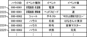
- Drawing 22 is a figure showing an example of household appliance event information which SNS server 2001 transmits. Note that the event type shown in FIG. 22 includes home appliance type information as necessary, and the house ID is identification information for specifying each home, and the device ID is used as needed. May be included.
- FIG. 23 When the GUI (graphical user interface image) of FIG. 23 is displayed on the display device 2008, when the home appliance event information in which the power of the washing machine in the row indicated by 2221 of FIG. 22 is turned on is received (a in FIG. The washing machine is currently used by displaying the device icon 2503 representing the washing machine of the other house in FIG. 23 using an animation effect in which the washing machine swings to the left and right as shown in FIG.
- a home icon 2505 representing another house in FIG. 23 can also be displayed by using a display such as (housekeeping master's title icon).
- the home title is determined by analyzing the operating status of the home appliance 2002 using sensing information (home appliance event information) received by the SNS server 2001 from the same home.
- the house title icon is not particularly limited to the above-described example, and various modifications are possible.
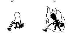
- the icon shown in FIG. 26B may be used as the beauty master title icon.
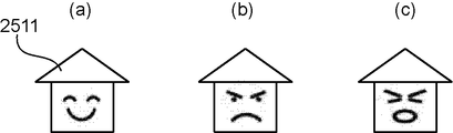
- a home icon 2505 representing another home in FIG. 23 can also be displayed by using a display effect such as a home icon 2511 representing a state.
- the state of the house is determined by analyzing the operation status of the home appliance 2002, etc., using the sensing information (home appliance event information) received by the SNS server 2001 from the same home.
- the home icon representing the state of the house is not particularly limited to the above example, and various modifications are possible. For example, the home icon representing the state of the angry face shown in (b) of FIG. It is also possible to use a home icon representing the state of the troubled face shown in (c).
- FIG. 30 is a diagram showing the configuration of the information sharing system according to the third embodiment of the present invention.
- the home appliance management server 3005 shown in FIG. 30 includes the state of the home appliance from the microwave 1002 etc. in each home registered in advance.
- Home appliance event information is transmitted, and information of each house is formed as screen information based on the type of home appliance event information and the occurrence frequency of home appliance event information, and the screen information is provided in response to a request of the display device 3000 or the like.
- the explanation of this point is omitted, and the features of the present embodiment will be described in detail below.
- the information sharing system illustrated in FIG. 30 includes a GW 1001, a microwave oven 1002, an IH cooker 1003, a TV 1004, a DB 1011, a display device 3000, a toothbrush 3001, a sensor 3002, a display device 3003, a GW 3004, and a home appliance management server 3005.
- home appliances such as the microwave oven 1002, the IH cooker 1003, the TV 1004, the toothbrush 3001, and the display device 3000 for displaying a GUI (graphical user interface image) are connected to the home appliance management server 3005 via the GW 1001.
- the display device 3003 for displaying the sensor 3002 and the GUI is connected to the home appliance management server 3005 via the GW 3004 to configure a network.
- the newly defined home appliance management server 3005 manages home appliances and sensors connected to the network and holds, in the DB 1011, appliance information (home appliance event information) according to the types of home appliances and sensors. .
- FIG. 35 is a diagram showing an example of home appliance event information.
- the home appliance event information illustrated in FIG. 35 is an example of home appliance event information acquired from the home appliance management server 3005, and for the home appliance type, the sensor type (mounted sensor type) mounted on the device and the sensor value of each sensor. Describes each specific event processing. Event processing can be described as an executable program, or there may be a setting file for executing the program, or link information (URL (Uniform Resource Locator) or pointer to a program or setting file) ) May be.
- URL Uniform Resource Locator
- the home appliance management server 3005 When a new home appliance (for example, the toothbrush 3001 or the sensor 3002) is found, the GW 1001 to which the toothbrush 3001 is connected, or the GW 3004 to which the sensor 3002 is connected Download from 3005
- the home appliance management server 3005 immediately displays the home screen displayed on the display device 3000 or the display device 3003 and the related community screen (graphical user interface) in order to immediately reflect the sensor information (home appliance event information) acquired from the toothbrush 3001 or the sensor 3002 Request to update the display of the image).
- Each home appliance or sensor may be directly connected to the home appliance management server 3005 by the home appliance management server 3005 substituting the GW process. Further, the display device 3000 and the display device 3003 do not have to be connected to the same GW as the home appliance or the sensor, and may be directly connected to the home appliance management server 3005.
- FIG. 31 is a diagram showing an example of an internal configuration of the GW 1001 shown in FIG.
- the internal configuration of the GW 3004 is the same as that shown in FIG. 31 and operates in the same manner as the GW 1001. Therefore, in the following description, the GW 1001 will be described as an example.
- the communication unit 3014 is connected to a network to perform information communication with a home appliance or a sensor (for example, the display device 3000 or the toothbrush 3001) or the home appliance management server 3005.
- the device information acquisition unit 3013 acquires home appliance event information corresponding to the type of a device (home appliance or sensor) connected to the network from the home appliance management server 3005.
- the home appliance event information acquired by the device information acquisition unit 3013 is stored in the device information storage unit 3012.
- home appliance event information shown in FIG. 34 can be used as a method of determining the type of the device connected to the network.
- the device ID shown in FIG. 34 is only required to uniquely identify a home electric appliance or a sensor, and may be, for example, a MAC address (Media Access Control address) or a serial number or the like. It may be Internet Protocol address).
- the home appliance type may be embedded in advance in a home appliance or a sensor, or may be set by the user by providing a setting means such as a GUI. Also, the home appliance type needs to be a code that has been agreed between at least the home appliance management server 3005, the GWs 1001 and 3004, the home appliance, and the sensor, but there is no need to manage with a character string. It may be any symbol.
- the appliance information acquisition unit 3013 can connect the home appliance via the communication unit 3014 when connected to the network. You can get the type.
- the event processing unit 3011 acquires home appliance event information of a home appliance or a sensor connected via the communication unit 3014 from the device information acquisition unit 3013, and performs event processing according to the acquired home appliance event information. Further, as the processing result of the event processing unit 3011, an event defined by the home appliance event information is specified as a result of operation of the home appliance or the sensor, and home appliance event information is notified to the display device 3000 or the home appliance management server 3005.
- produces, for example, based on household appliance event information notified from a household appliance or a sensor, the power supply ON / OFF etc. It is possible to define a state change notification event indicating a state change or the like, and an update notification event of sensor information indicating that various sensor values of home appliances and sensors have been updated. Also, the event or event process is not limited to a specific event or event process, and any event or process can be defined.
- the display update instruction unit 3010 can perform event processing on the new home appliance or sensor by the event processing unit 3011 In this case, the display unit 3000 is instructed to update the display using the communication unit 3014.
- the display update instruction unit 3010 may explicitly instruct the display device 3000 to perform display update, or the event processing unit 3011 notifies the display device 3000 of a display update event. It is also good.
- a part or all of the configuration of the GW 1001 can be included in the home appliance management server 3005.
- the display device, the home appliance and the sensor are directly connected to the home appliance management server 3005.
- the role of the GW is a bridge function of a home appliance or a sensor with a home appliance management server
- components other than the communication unit may be delegated to the home appliance management server.
- the display device such as the display device 3000 includes this configuration, the display device may directly receive the information from the home appliance or the sensor, and the received information may be reflected on the GUI.
- FIG. 32 is a flowchart showing an example of processing of the GW 1001 when a new home appliance or sensor is found in the present embodiment.
- the GW 1001 determines whether the connected device (home appliance or sensor) is a newly connected device (step S3021). If the connected home appliance or sensor is a newly connected device (YES in step S3021), the device information acquiring unit 3013 acquires home appliance event information of a new connected device from the home appliance management server 3005 (step S3022). If the home appliance event information has already been acquired from the home appliance management server 3005, it may not be acquired.
- the device information acquisition unit 3013 stores the acquired home appliance event information in the device information storage unit 3012 (step S3023), and the event processing unit 3011 uses the new home appliance event information stored in the device information storage unit 3012.
- the processing based on the above is validated (step S3024).
- the device information acquisition unit 3013 notifies the home appliance management server 3005 that the new device is connected to the GW 1001 and becomes available (step S3025), and the display update instruction unit 3010 displays all of the displayed GUIs. Re-reading or re-drawing of the GUI is instructed to the display device 3000 using the communication unit 3014 (step S3026). As a result, the GUI related to the information acquired from the newly connected home appliance or sensor is updated, and the information related to the new home appliance or sensor is displayed on the GUI.
- FIG. 33 is a flowchart showing an example of processing of the display device 3000 for automatically displaying the related community when a new home appliance or sensor is connected to the network
- FIG. 36 shows the display device 3000. It is a figure showing an example of GUI at the time of displaying a related community automatically, when a new household appliance and a sensor are connected to a network as an example of GUI updated.
- the display device 3003 is also configured and operates in the same manner as the display device 3000. Therefore, in the following description, the display device 3000 will be described as an example.
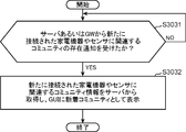
- the display device 3000 determines whether a notification of the presence of a community associated with a newly connected home appliance or sensor is received from the home appliance management server 3005 or the GW 1001 (step S3031).
- the display device 3000 changes the community information related to the newly connected home appliance or sensor to the home appliance management server
- the acquired community information is displayed on the GUI as a new arrival community acquired from 3005 (step S3032).
- the GUI related to the information acquired from the newly connected home appliance or sensor is updated, and the information related to the new home appliance or sensor (community list information) is a GUI (graphical user) Interface image).
- a GUI shown in FIG. 36 is displayed.
- a recommended community image 3601 is displayed as community list information at the lower right of the screen, and a recommended community related to a new home appliance or sensor is automatically displayed on the GUI. Is displayed.
- the display device 3000 or the like acquires the community list information related to the new device, and the community list information is displayed in the graphical user interface image. Is displayed superimposed.
- the GWs 1001 and 3004 detect a new device (home appliance or sensor), they can acquire home appliance event information that defines event processing for a new device, so all the GUIs are automatically displayed and updated. It can automatically display and update the community list related to new devices (home appliances and sensors). Therefore, in the present embodiment, the display of the GUI can be updated without bothering the user's operation.
- home appliances and display devices are described separately in this embodiment, home appliances having a screen such as the TV 1003 may have a function as a display device.
- FIG. 37 is a diagram showing the configuration of the information sharing system according to the fourth embodiment of the present invention.
- the home appliances 40141, 40142 to the server 40110 are registered in advance in the respective homes 40111, 40112, 40113 via the GW 40130.
- Home appliance event information including the state of the device is transmitted, and information of each house is formed as screen information based on the type of home appliance event information and the occurrence frequency of home appliance event information, and the screen information is sent to the request of the display device 40143
- the description is omitted, and the features of the present embodiment will be described in detail below.
- the information sharing system illustrated in FIG. 37 includes a server 40110, a plurality of GWs 40130, a plurality of home appliances 40141 and 40142, and a plurality of display devices 40143.
- the server 40110 acquires the operation statuses of the home appliances 40141 and 40142 as home appliance event information, detects the related community according to the operation status, and detects UI (User Interface) information of the community via the GW 40130. , Home appliances 40141, 40142 to send.
- UI User Interface
- the home appliance event information includes operation information indicating the operation status of the home appliances 40141 and 40142, and home appliance type information indicating the type of the home appliances 40141 and 40142, as information on the state change of the home appliances 40141 and 40142.
- the server 40110 determines the community associated with the type of the device specified by the home appliance type information as the community to which the user relates, and the display device 40143 selects the community according to the operation state of the device specified by the operation information. Display a UI image (user interface image) related to
- the internet can be used as a network which connects server 40110 and GW40130, if home appliance event information of home appliances 40141 and 40142 can be transmitted to server 40110, another network such as a cellular phone network can be used. It may be
- the GW 40130 is a device having a function of connecting to the server 40110 via a network, and may be a router-like device or a device in which a gateway function is embedded in a home appliance.
- home appliances such as a refrigerator, a washbasin, and an air conditioner which are constantly supplied with power can also function as a GW by providing a function of connecting to a network.
- the home appliances 40141 and 40142 are Internet appliances having a network connection function with the GW 40130.
- the Internet home appliance is a concept showing home appliances and equipments having a function of connecting to various networks including the Internet, and AV equipment (audio-video equipment) such as television, recorder equipment, and remote control equipment thereof
- AV equipment audio-video equipment
- home appliances such as scales, toothbrushes, dryers, etc. and white goods.
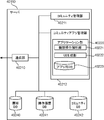
- FIG. 38 shows an exemplary configuration of server 40110 shown in FIG.
- the server 40110 includes a communication unit 40210, a community management unit 40211, a community application management unit 40212, a customer DB 40240, an operation history DB 40241, and a community DB 40242.
- the community application management unit 40212 manages a plurality of application units 40220, and each application unit 40220 includes a device operation analysis unit 40221, a UI generation unit 40222, and an application DB 40223.
- each DB is provided in the server 40110.
- the present invention is not particularly limited to this example, and an external DB may be used as in the first embodiment.
- Communication unit 40210 establishes data transmission / reception status with home appliances 40141 and 40142 via GW 40130 connected to the network, and performs data communication.
- the community management unit 40211 manages the communities associated with the home appliances 40141 and 40142. Specifically, the community management unit 40211 identifies the community to which the user relates from the home appliance type information of the home appliances 40141 and 40142 acquired from the communication unit 40210, and operates the household appliances 40141 and 40142 acquired from the communication unit 40210. The status is sent to the community application management unit 40212 to request generation of a UI. In addition, the community management unit 40211 stores the operation status (home appliance event information) of the home appliances 40141 and 40142 acquired from the communication unit 40210 in the operation history DB 40241.
- the community application management unit 40212 manages an application unit 40220 associated with each community. Specifically, the community application management unit 40212 determines the operation status of the home appliances 40141 and 40142 acquired from the community management unit 40211, and generates a UI image to be provided to the user.
- the device operation analysis unit 40221 acquires related home appliance event information from the operation history DB 40241, and determines the context of the user from the history of device operations. Then, the device operation analysis unit 40221 requests the UI generation unit 40222 to generate a UI image to be displayed to the user according to the determined context. The UI generation unit 40222 determines a display area of the display device 40143, and generates a UI image according to the display area.
- the application DB 40223 stores information used by an application executed by the application unit 40220. For example, when the application displays a log in the past, the application DB 40223 associates information to be stored with the user ID or GWID of the customer DB 40240 and stores the information internally.
- the customer DB 40240 holds, for each user, information of various IDs, registration information, and references to the operation history of the user. Using the information, the community management unit 40211 and the community application management unit 40212 determine the community and the UI image according to the user.
- FIG. 39 is a view showing an example of the customer database stored in the customer DB 40240 shown in FIG. 38 and an example of the user's operation history database stored in the operation history DB 40241.
- each information of user ID 40301, GW ID 40302, registered name 40303 of user, registered community 40304 of user, owned device 40305, and reference 40306 to operation history is stored in table form in customer DB 40240 There is.
- the user ID 40301 is an identifier that uniquely identifies a user.
- the GW ID 40302 is an identifier that uniquely identifies the GW 40130.
- a house ID an identifier uniquely identifying a home
- the house is used. You may use an ID.
- the house ID may be managed by the server 40110. However, when registering a newly acquired home appliance or the like to the server 40110, the house ID is registered with respect to the home appliance, and when communicating from the home appliance The method of notifying the server 40110 of the house ID may be used.
- the information of the registered name 40303 may be either a temporary name or a real name of a user used in the community.
- the information of the registered community 40304 is the name of the community registered by the user.
- the information on the owned device 40305 indicates a list of home appliances owned by the user.
- the information on the reference 40306 to the operation history is reference information to the operation history DB 40241 storing the history of the operation of the owned device 40305 by the user.
- information regarding the user ID “U0001” is stored in the line 40310, and information regarding the user ID “U0002” is stored in the line 40320.
- the operation history DB 40241 stores operation history information managed for each user as home appliance event information.
- the lower part of FIG. 39 shows an example of the operation history database concerning the user with the user ID “U0001” (registered name “Haru”) shown in the upper part of FIG.
- each information of year / month / day 40401, time 40402, operation device 40403, and operation details 40404 is stored in the operation history DB 40241 in a table format.
- the information of year / month / day 40401 indicates the date when the operation was performed.
- the information of time 40402 indicates the time when the operation was performed.
- the information on the operation device 40403 indicates home appliance type information indicating the type of the device on which the operation has been performed.
- the information of the operation details 40404 indicates operation information indicating an operation performed on the device of the operation device 40403.
- the list information of the operation details that may occur for each operation device may be determined in advance at the time of product shipment and stored in advance in the operation history DB 40241, or by a policy of updating at any time on the server 40110 It may be.
- the date and time when the power of the weight scale is turned on are stored in the row 40410, and the row 40420 is for the person registered in the weight scale.
- the date and time when the selection operation button (selection of the person associated with the button No. 1) is pressed is stored.
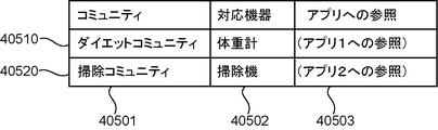
- the community DB 40242 stores association information between a list of communities managed by the server 40110 and corresponding devices (home appliances).
- FIG. 40 is a diagram showing an example of a community database stored in the community DB 40242 shown in FIG.
- information of the community 40501, the compatible device 40502, and the reference 40503 to the application is stored in the form of a table in the community DB 40242.
- the information on the community 40501 indicates a list of communities managed by the server 40110.
- the information of the corresponding device 40502 indicates home appliance type information indicating the type of the associated device for each community.
- the information on the compatible device 40502 is not particularly limited to the above example, and, for example, the compatible device 40502 may be managed by being divided into a compatible required device and a compatible device.
- reference information to an area for storing a program of this community is held. Further, in FIG. 40, as an example, reference information to the corresponding device and application 1 of the diet community is stored in line 40510, and reference information to the corresponding device and application 2 of the cleaning community is stored in line 40520.
- FIG. 41 is a flowchart showing an example of control processing of the server 40110 shown in FIG.
- the community management unit 40211 acquires the GWID and the operation history of the device from the communication unit 40210 (step S4061).
- the community management unit 40211 refers to the customer DB 40240 and adds the operation history to the operation history DB 40241 after acquiring the user ID associated with the acquired GWID, the registered community, and the information on the reference to the operation history. Furthermore, the information on the acquired registered community is output to the community application management unit 40212 (step S4062).
- the community application management unit 40212 refers to the community DB 40242, acquires reference information to the application associated with the acquired registered community, and acquires reference information to the application, user ID, and reference information to the operation history.
- the application unit 40220 executes the corresponding application using the reference information to the application, analyzes the operation history acquired using the reference information to the operation history by the device operation analysis unit 4021, and A UI image to be provided is generated by the UI generation unit 40222, and the generated UI image is transmitted to the user (step S4064).
- a wash basin (a device having not only a wash basin function as a home appliance but also a function of the GW 40130 and a display device 40143) as a GW 40130 is used as a home appliances 40141 as a wash basin on which a network function and a display function are installed.
- An example of control processing of the server 40110 when using a weight scale will be described in detail.
- FIG. 42 is a perspective view of a wash basin 40130 equipped with a network function and a display function.
- the wash basin 40130 can be connected to the Internet and can also be connected to a household electric appliance 40142 such as a weight scale 40141 and other toothbrushes present around the wash basin 40130.
- the mirror surface of the wash basin 40130 is a half mirror, and an image displayed by the built-in display and an image reflected on the mirror surface can be superimposed and displayed.
- the wash basin 40130 can change the display content for each area of the mirror surface.
- the device area 40701 is an area for displaying a home appliance icon of a weight scale 40141 which can be connected to the wash basin 40130 and the other home appliances 40142
- the display method according to the current connection state with the wash basin 40130 it is possible to visualize connected devices such as home appliances connected with the wash basin 40130.
- FIG. 43 is a diagram showing a display example of connected devices in the device area shown in FIG.
- a list of home appliances connectable to the wash basin 40130 such as a weight scale icon 40801 representing a weight scale 40141, a toothbrush icon 40802 representing a toothbrush, and a dryer icon 40803
- a weight scale icon 40801 representing the weight scale 40141 lights up, and the home appliance or the like in connection can be displayed in an easily understandable manner for the user.
- a log area 40702 shown in FIG. 42 is an area for displaying data measured by a weight scale 4014 or the like to the user in an easy-to-understand manner, and not only the weight at the timing of weight measurement but also past logs (measurement data Etc.) can also be displayed.
- FIG. 44 is a diagram showing a display example of measurement data in the log area shown in FIG.
- a region 40901 in the upper part of the log area 40702 when the camera is mounted on the wash basin 40130, a picture or a picture is taken at the timing of weight measurement, and the weight is not only a number but an image of the photographed user Can also be displayed as a figure change.
- the display orientation may be changed by the user operation.
- the past weight is displayed in a clear manner in a graph or the like. Further, by selecting a measurement point on this graph, the figure of the user at the time of the selection can be displayed in the area 40901.
- the SNS area 40703 shown in FIG. 42 is a community area for displaying an image related to the community in which the user participates, and the user operates the home appliance etc. by displaying the situation of another user participating in the community. You can improve your motivation.
- FIG. 45 is a diagram showing a display example of the community in the SNS area shown in FIG. For example, in an area 41010 at the top of the SNS area 40703, ranking information of users who participate in the same community is displayed.
- the wash basin 40130 transmits the measurement result of the weight data measured by the weight scale 40141 to the server 40110.
- the device operation analysis unit 40221 in the application unit 40220 of the diet community detects that the weight is measured, and changes the weight as compared with other community participants in the UI generation unit 40222 Create a ranking UI image by.
- the created UI image is transmitted to the wash basin 40130, and a UI image of ranking due to weight change is displayed in an area 41010 shown in FIG.
- the user name 41011 is a registered name registered in the customer database of FIG.
- the class display 41012 classifies the weight and displays a change in the user's class.
- a symbolic thick entertainer, a thin entertainer, etc. can also be used as expression of a class, for example.
- BMI Body Mass Index
- an area 41020 in the middle part of the SNS area 40703 is an area representing tweet information between members belonging to the present community.
- the tweet information 41021 represents a tweet automatically generated when the weight of the user exceeds the rank, and it is possible to notify the user belonging to the same community of the change of the rank only by measuring the weight. .
- by receiving a message from a friend as in the case of the tweet information 41022 it is possible to receive a seal for the weight approaching the goal.
- messages from friends can be encouraging when weight gain and rank rise. In this way, the user can easily see surrounding reactions to his or her behavior, and can thus invite the user to continue weight management while maintaining motivation.
- An area 41030 in the lower part of the SNS area 40703 is an area in which a part or all of the community participants are displayed in a list.
- the display target such as by city or by age
- an expression for example, a sparkling expression
- the user can feel a loose connection with the user belonging to the same community instead of performing his / her own weight management based on the measurement result on the weight scale 40141 (for example, rank display (ranking display) , And by displaying tweet information and displaying a list of users, it is possible to perform weight management more enjoyable, which can lead to maintenance of motivation.
- rank display for example, rank display (ranking display)
- the central area 40704 shown in FIG. 42 is an area where the user standing in front of the mirror is the most visible, and therefore, it can be assumed that utilization such as temporarily displaying the operation results of the user's home appliances etc. .
- the user can display the result when the weight measurement is completed with the weight scale 40141 not only on the liquid crystal panel of the weight scale 40141, but also on the central region 40704 of the wash basin 40130 for a fixed time. The results can be better understood at a glance.
- the UI display by cooperation between the weight scale 40141 and the wash basin 40130 is described as an example, but depending on the type of the linked home electric appliance etc., the user displays it superimposed on the image of the user
- the user displays it superimposed on the image of the user
- the position and content of the display area described above are an example, and the position and content of the display area can be freely determined according to the associated home electric appliances and the participating community.
- the present invention is not limited to the contents described herein, and can be widely applied.
- FIG. 46 is a sequence diagram showing an example of control processing of the server 40110 using the wash basin 40130 and the weight scale 40141.
- the weight scale 40141 When the user turns on the weight scale 40141, the weight scale 40141 performs data communication with the wash basin 40130 (step S4111). At this time, the wash basin 40130 transmits the “GWID” and the information on the operation device and the operation detail information as “home appliance operation” to the server 40110 (step S4112).
- the server 40110 generates a UI image to be displayed on the wash basin 40130 according to the control process of FIG. 41 (step S4113). Then, the server 40110 transmits the generated UI image to the wash basin 40130 (step S4114). Although the UI image is directly transmitted here, the access destination to the server 40110 may be transmitted to the wash basin 40130, and the wash basin 40130 may request the server 40110 to acquire the UI image. It may be a method of transmitting the parts to the wash basin 40130.
- the wash basin 40130 displays the UI image specified by the server 40110 (step S4115).
- the wash basin 40130 displays a weight scale icon 40801 in the device area 40701 shown in FIG. 43, and changes the color of the weight scale icon 40801 to indicate that it is currently connected to the weight scale. Do.
- the weight scale 40141 transmits “weight scale” and “person selection information”, which are information of the operation device, to the wash basin 40130 (step S4116).
- the wash basin 40130 transmits “GWID” and information on the operation device and operation detail information as “home appliance operation” to the server 40110 (step S4117).
- the server 40110 generates a UI image to be displayed on the wash basin 40130 according to the control process of FIG. 41 (step S4118). Then, the server 40110 transmits the generated UI image to the wash basin 40130 (step S4119).
- wash basin 40130 displays the UI image specified by the server 40110 (step S4120).
- wash basin 40130 graphically displays the past weight in area 40902 shown in FIG. 44, and graphically displays the past weight information of the selected user in a graph or the like.
- user's figure information may be displayed.
- an image captured at a timing when the user turns in an appropriate direction may be displayed.
- the weight scale 40141 transmits “weight scale” and “measurement information” which are information of the operation device to the wash basin 40130 (step S4122).
- the wash basin 40130 transmits the information of the operation device and the operation detail information as “GWID” and “measurement information” to the server 40110 (step S4123).
- the server 40110 generates a UI image to be displayed on the wash basin 40130 according to the control process of FIG. 41 (step S4125). Then, the server 40110 transmits the generated UI image to the wash basin 40130 (step S4126).
- the wash basin 40130 displays the UI image specified by the server 40110 (step S4127).
- wash basin 40130 displays ranking information and the like in areas 41010 to 41030 shown in FIG.
- the wash basin 40130 can display, as a user interface image, a relation between one user belonging to the community and another user in class.
- the image shown in FIG. 45 is displayed here as the UI image of the measurement result
- the image shown in FIG. 45 is displayed in step S4120, and in step S4127, the SNS is displayed according to the measurement result.
- the area of the area 40703 may be changed.
- the ranking of the user name “Haru” in the area 41010 changes to first place.
- the tweet information 41021 of the area 41020 is automatically tweet, and accordingly, the message from the friend is also tweet.
- the user icon 41031 of the user name "Haru” is changed from a bantam-class icon to a lightweight icon, and a glitter mark indicating a class change is displayed.
- a UI image which is community information related to another community participant can be displayed by the operation of the home appliance or the like. It is possible to maintain the motivation of the user who operates the etc.
- FIG. 47 is a diagram showing a configuration of the information sharing system according to the fifth embodiment of the present invention
- FIG. 48 is a diagram showing an example of a display screen displayed on the display device shown in FIG.
- home appliance event information including the state of the home appliance from the home appliance in each home registered in advance to the server 5011 via the GW 5013
- the information of each house can be formed as screen information based on the type of home appliance event information and the occurrence frequency of home appliance event information, and the screen information can be provided in response to the request of the display device 5016.
- explanation is omitted and the characteristic part of this embodiment is explained in detail below.
- the information sharing system illustrated in FIG. 47 includes a server 5011, a DB 5012, a GW 5013, a dust sensor 5014 which is an example of a sensor, a cleaner 5015 which is an example of a home appliance, and a display device 5016.
- a server 5011 a server 5011
- a DB 5012 a GW 5013
- a dust sensor 5014 which is an example of a sensor
- a cleaner 5015 which is an example of a home appliance
- a display device 5016 a display device 5016.
- the dust sensor 5014 detects the amount of dust sucked.
- the GW 5013 acquires the amount of dust sucked by the vacuum cleaner 5015 from the dust sensor 5014 and notifies the server 5011 as household appliance event information.
- the server 5011 When the amount of trash exceeds a preset value, the server 5011 gives the item of the trash bag to the user on the SNS service as a reward. Specifically, the server 5011 stores the acquired number of garbage bags in the DB 5012 for each user. The server 5011 generates a GUI image (graphical user interface image) according to the acquired number of garbage bags, and causes the display device 5016 to display the GUI image via the GW 5013. For example, a trash bag icon 5018 shown in FIG. 48 is displayed on the display screen of the display device 5016 as a GUI image.
- GUI image graphical user interface image
- FIG. 49 is a flow chart showing an example of processing in the information sharing system shown in FIG.
- the GW 5013 acquires the amount of dust absorbed by the vacuum cleaner 5015 from the dust sensor 5014 and notifies the server 5011 (step S5021).
- the server 5011 determines whether the amount of dust exceeds a preset value (step S5022), and if the amount of dust does not exceed the preset value (NO in step S5022), step S5021 Repeat the process of
- step S5022 if the amount of trash exceeds the preset value (YES in step S5022), the user acquires a trash bag, and the server 5011 stores the acquired number of trash bags in the DB 5012 (step S5023). Next, the server 5011 creates a GUI image according to the acquired number of trash bags, and displays a trash bag icon 5018 on the display screen of the display device 5016 via the GW 5013 (step S5024).
- the dust bag icon 5018 is increased on the display screen of the display device 5016 according to the amount of dust sucked by the vacuum cleaner 5015, and the number of obtained dust bags is DB 5012 Stored in Note that the display device 5016 and the dust sensor 5014 do not necessarily need to communicate with the server 5011 via the GW 5013, and a network that directly communicates may be used.
- FIG. 50 is a flow chart showing a first extension process in the information sharing system shown in FIG. 47
- FIG. 51 is a view showing another example of the display screen displayed on the display device shown in FIG. Since steps S5021 and S5022 shown in FIG. 50 are the same processes as steps S5021 and S5022 shown in FIG. 49, the description thereof is omitted, and the process different from FIG. 49 will be described in detail.
- the server 5011 randomly determines the type of dust bag acquired by the user (Ste S5041)
- the number and type of the acquired garbage bag are stored in the DB 5012 for each user (step S5042).
- the server 5011 creates a GUI image according to the number and type of the acquired trash bag, and displays an icon of the trash bag on the display screen of the display device 5016 via the GW 5013 (step S5043). For example, three different types of trash bag icons 5018 shown in FIG. 51 are displayed on the display screen of the display device 5016 as GUI images.
- the trash bag icon 5018 is increased on the display screen of the display device 5016 according to the amount of vacuumed by the vacuum cleaner 5015, and the number and type of trash bags obtained is DB5012. It can be stored in random, different colored and patterned trash bags.
- FIG. 52 is a flow chart showing the second extension processing in the information sharing system shown in FIG. 47
- FIG. 53 is a view showing still another example of the display screen displayed on the display device shown in FIG. Since steps S5021 to S5042 shown in FIG. 52 are the same processes as steps S5021 to S5042 shown in FIG. 50, the description thereof is omitted, and the processes different from FIG. 50 will be described in detail.
- the server 5011 calculates the ratio of the acquired types of trash bags (the trash bag collection yield) with respect to all types of trash bags (step S5061).
- the server 5011 creates a GUI image that displays trash bag icons and trash bag collection yields according to the number and type of trash bags acquired, and the trash bags are displayed on the display screen of the display device 5016 via the GW 5013. Icon and the trash bag collection yield are displayed (step S5062). For example, as the GUI image, icons 5018 of three different types of trash bags shown in FIG. 53 and information 5051 indicating “the trash bag collection rate 20%” are displayed on the display screen of the display device 5016.
- the trash bag icon 5018 is increased on the display screen of the display device 5016 according to the amount of vacuumed by the vacuum cleaner 5015, and the number and type of trash bags obtained is DB5012. As well as being able to obtain different trash bags of different colors and patterns, it is possible to display the percentage of trash bags collected so far.
- FIG. 54 is a diagram showing a configuration of another information sharing system according to the fifth embodiment of the present invention
- FIG. 55 is a diagram showing an example of a display screen displayed on the display shown in FIG. 54.
- the information sharing system illustrated in FIG. 54 includes a server 5011, a DB 5012, a GW 5013, a dust sensor 5014 which is an example of a sensor, a cleaner 5015 which is an example of a home appliance, a display device 5016, and an audio device 5072.
- the dust sensor 5014 detects the amount of dust sucked.
- the GW 5013 acquires the amount of dust sucked by the vacuum cleaner 5015 from the dust sensor 5014 and notifies the server 5011 of the amount.
- the server 5011 When the amount of trash exceeds a preset value, the server 5011 gives the item of the trash bag to the user on the SNS service as a reward. Specifically, the server 5011 randomly determines the type of trash bag to be acquired, and stores the number and type of trash bags acquired in the DB 5012 for each user.
- the server 5011 obtains the ratio of the types of the acquired trash bags to the types of all the trash bags, and sets it as the trash bag collection yield.
- the server 5011 causes the display device 5016 to display a GUI image according to the number and type of the acquired trash bags via the GW 5013. For example, according to the number and type of the acquired trash bags, a trash bag icon 5018 shown in FIG. 55 and information 5051 indicating "100% trash bag collection rate" are displayed on the display screen of the display device 5016. .
- the server 5011 performs level up display 5071 on the display screen of the display device 5016 via the GW 5013.
- the user acquires BGM (background music) as a reward, and the server 5011 transmits BGM data to the audio device 5072 via the GW 5013, and BGM is reproduced from the audio device 5072.
- BGM background music
- FIG. 56 is a flow chart showing an example of processing in the information sharing system shown in FIG. Since steps S5021 to S5062 shown in FIG. 56 are the same processes as steps S5021 to S5062 shown in FIG. 52, the description thereof is omitted, and the processes different from FIG. 52 will be described in detail.
- step S5081 determines whether the trash bag collection yield has reached 100% (step S5081), and if the trash bag collection yield has not reached 100% (step S5081) NO), end the process. On the other hand, if the trash bag collection yield is 100% (YES in step S5081), the server 5011 causes the display of the display device 5016 to display a level up display via the GW 5013 (step S5082). Next, the server 5011 transmits BGM data to the audio device 5072 via the GW 5013, and reproduces BGM from the audio device 5072 (step S5083).
- the trash bag icon 5018 is increased on the display screen of the display device 5016 according to the amount of vacuumed by the vacuum cleaner 5015, and the number and type of trash bags obtained is DB5012.
- the percentage of trash bags collected so far.
- the user's cleaning level rises, BGM can be given to the user, and BGM is reproduced from the audio device 5072.
- the screen display when operating the vacuum cleaner is realized.
- FIG. 57 shows a configuration of the information sharing system according to the sixth embodiment of the present invention
- FIG. 58 shows an example of a display screen displayed on the display shown in FIG.
- home appliance event information including the state of the home appliance from the home appliance in each home registered in advance to the server 5011 via the GW 5013
- the information of each house can be formed as screen information based on the type of home appliance event information and the occurrence frequency of home appliance event information, and the screen information can be provided in response to the request of the display device 5016.
- explanation is omitted and the characteristic part of this embodiment is explained in detail below.
- the information sharing system illustrated in FIG. 57 includes a server 5011, a DB 5012, a GW 5013, sensors 6011 and 6012, a cleaner 6013 and an iron 6014 which are examples of home appliances, and a display device 5016.
- the sensors 6011 and 6012 detect the amount of movement.
- the GW 5013 acquires moving amounts of the vacuum cleaner 6013 and the iron 6014 from the sensors 6011 and 6012, and notifies the server 5011 as home appliance event information.
- the server 5011 calculates the consumed calories at the time of performing the housework according to the moving amount of the vacuum cleaner 6013 and the iron 6014, and stores the consumed calories in the DB 5012 for each user. Also, the server 5011 generates a GUI image (graphical user interface image) according to the consumed calories, and causes the display device 5016 to display the GUI image via the GW 5013. For example, as GUI images, as shown in FIG. 58, the consumed calories of the respective home appliances (the vacuum cleaner 6013 and the iron 6014) and information 6015 shown as the total value are displayed on the display screen of the display device 5016.
- GUI images as shown in FIG. 58, the consumed calories of the respective home appliances (the vacuum cleaner 6013 and the iron 6014) and information 6015 shown as the total value are displayed on the display screen of the display device 5016.
- FIG. 59 is a flow chart showing an example of processing in the information sharing system shown in FIG.
- the server 5011 obtains moving amounts of the vacuum cleaner 6013 and the iron 6014 from the sensors 6011 and 6012 via the GW 5013, and calculates consumed calories from the amount of movement of the vacuum cleaner 6013 and the iron 6014 (step S6021).
- the server 5011 generates a GUI image that displays the consumed calories of each home appliance and the total value, and displays the GUI image on the display screen of the display device 5016 via the GW 5013 (step S6022).
- the consumed calories are automatically displayed according to the amount of movement of the vacuum cleaner 6013 and the iron 6014 Can.
- FIG. 60 is a flowchart showing a first extension process in the information sharing system shown in FIG. 57
- FIG. 61 is a view showing another example of the display screen displayed on the display device shown in FIG. Since steps S6021 and S6022 shown in FIG. 60 are the same processes as steps S6021 and S6022 shown in FIG. 59, the description thereof is omitted, and the process different from FIG. 59 will be described in detail.
- the server 5011 determines the food according to the consumed calories, creates a GUI image including the determined picture of the food, and the food is displayed on the display screen of the display device 5016 via the GW 5013. Is displayed (step S6041). For example, as a GUI image, as shown in FIG. 61, a picture 6031 of food (eg, rice ball) according to the consumed calories is displayed on the display screen of the display device 5016.
- a GUI image as shown in FIG. 61, a picture 6031 of food (eg, rice ball) according to the consumed calories is displayed on the display screen of the display device 5016.
- consumed calories can be displayed according to the amount of movement of the vacuum cleaner 6013 and the iron 6014, and a picture of food corresponding to the displayed calories can be displayed.
- FIG. 62 is a flowchart showing a second extension process in the information sharing system shown in FIG. 57
- FIG. 63 is a diagram showing still another example of the display screen displayed on the display device shown in FIG. Since steps S6021 to S6041 shown in FIG. 62 are the same as steps S6021 to S6041 shown in FIG. 60, the description thereof is omitted, and the processes different from FIG. 60 will be described in detail.
- the server 5011 adds the growth degree of the virtual pet according to the acquired food (step S6061), and creates a GUI image including a picture of the virtual pet according to the growth degree, A picture of a virtual pet is displayed on the display screen of the display device 5016 via the GW 5013 (step S6062). For example, as shown in FIG. 63, a picture 6051 of a virtual pet according to the degree of growth is displayed on the display screen of the display device 5016 as a GUI image.
- the consumed calories can be displayed according to the amount of movement of the vacuum cleaner 6013 and the iron 6014, and the picture of the food corresponding thereto can be displayed according to the displayed calories. Furthermore, the food described above can be obtained as an item, and the pet can be grown by feeding it to a virtual pet. As described above, in the present embodiment, the screen display when the home appliance such as the vacuum cleaner and the iron is operated is realized.
- an information sharing method is an information sharing method for providing a graphical user interface image for a plurality of users to share information on a device in a home, which is a plurality of devices in the home.
- a home determination step of determining a home to be displayed on the graphical user interface image according to the priority is an information sharing method for providing a graphical user interface image for a plurality of users to share information on a device in a home, which is a plurality of devices in the home.
- information on the state change of a plurality of devices in the home is received as home appliance event information, and the home should be displayed on the graphical user interface image according to the occurrence frequency of home appliance event information in each home Is determined, and according to the priority, a home to be displayed on the graphical user interface image is determined. Therefore, a plurality of users can share the information of the device state change that has actually occurred, and thus it is possible to provide a more attractive graphical user interface image with enhanced information reality and real-time capability. In addition, the reality and real-time nature of information can be enhanced compared to existing SNSs, and services that can enjoy more attractive content can be provided.
- the home appliance event information includes home appliance type information indicating the type of the device, and the priority determination step classifies the home appliance event information for each type of the device using the home appliance type information, and the type of the appliance It is preferable to determine the priority of the home to be displayed on the graphical user interface image according to the occurrence frequency of the home appliance event information.
- the display state of the device icon representing the device in the home can be changed and displayed in the graphical user interface image. It is possible to display the state change of the related device in an easy-to-understand manner for the user.
- the home appliance event information includes home appliance type information indicating the type of the device, and housework type information indicating the type of housework associated with the type of the device identified by the home appliance type information, and the priority determination step includes The home appliance event information is classified by housework type using the housework type information, and a home priority to be displayed according to the occurrence frequency of home appliance event information associated with the housework type selected by the user It is preferable to determine
- the display state of a home icon representing a home determined in the home determination step is changed and displayed on the graphical user interface image according to the occurrence frequency of home appliance event information associated with the type of household work selected by the user It is preferable to further include a display step.
- the display state of the home icon representing the home can be changed and displayed on the graphical user interface image according to the occurrence frequency of the home appliance event information associated with the type of household work selected by the user. It is possible to clearly display the user's in-home status of other users who are interested in the selected household chores.
- the message after receiving message information including request information requesting display linked to the type of device selected by the user or the type of housework, and the message input by the user, the type of device specified by the request information or Since the message is displayed superimposed on the graphical user interface image when the home appliance event information associated with the type of household chores is received, the message can be displayed at the timing of the state change of the device, and the message transmission For parties, when sending a message, the sender's message can be associated with home appliance event information supporting it more simply, so that it is possible for the sender of the message to provide an attractive information sharing service.
- the display step preferably displays a home icon representing a home determined in the home determination step on the graphical user interface image and superimposes and displays the message in the vicinity of the home icon.
- the display step displays a device icon representing a home device determined in the home determination step on the graphical user interface image and superimposes and displays the message in the vicinity of the device icon.
- the home appliance event information includes home appliance type information indicating the type of the device, and when the home appliance event information is received when the graphical user interface image is displayed, the home appliance event is displayed from the graphical user interface image. It is preferable to further include a transition step of causing the display screen to transition to a community image related to the type of the appliance specified by the home appliance type information included in the information.
- the display screen can be changed from the graphical user interface image to the community image related to the type of the device according to the device used by the user, and the type of the device is related to the type of the device
- the display screen can be changed from a community image to a graphical user interface image.
- the community list information related to the new device is displayed superimposed on the graphical user interface image, so the community related to the new device is not disturbed by the user's operation.
- the list information can be superimposed on the graphical user interface image to automatically update the display screen.
- the home appliance event information includes operation information indicating the operation status of the device and home appliance type information indicating the type of the device, and the user associates the community associated with the type of the appliance specified by the home appliance type information It is preferable to further include a display step of determining a related community and displaying a user interface image related to the community according to the operation state of the device specified by the operation information.
- the community associated with the device type specified by the home appliance type information is determined as the community to which the user relates, and the user associated with the determined community according to the operation state of the device specified by the operation information Since the interface image is displayed, when the user participates in the community, it is possible to automatically display a user interface image associated with another community participant by the operation of the device.
- the device preferably includes a wash basin having a gateway function, and a weight scale, and the display step preferably displays, as the user interface image, a relationship between one user belonging to the community and another user. .
Landscapes
- Engineering & Computer Science (AREA)
- Business, Economics & Management (AREA)
- Strategic Management (AREA)
- Entrepreneurship & Innovation (AREA)
- Human Resources & Organizations (AREA)
- General Physics & Mathematics (AREA)
- Physics & Mathematics (AREA)
- Operations Research (AREA)
- Quality & Reliability (AREA)
- Tourism & Hospitality (AREA)
- Marketing (AREA)
- General Business, Economics & Management (AREA)
- Economics (AREA)
- Theoretical Computer Science (AREA)
- Data Mining & Analysis (AREA)
- Automation & Control Theory (AREA)
- General Engineering & Computer Science (AREA)
- Human Computer Interaction (AREA)
- Computer Networks & Wireless Communication (AREA)
- Signal Processing (AREA)
- Information Transfer Between Computers (AREA)
- Management, Administration, Business Operations System, And Electronic Commerce (AREA)
- User Interface Of Digital Computer (AREA)
- Computing Systems (AREA)
Abstract
Description
本実施の形態では、例えば、ユーザ操作などによって発生する家庭内にある家電機器やセンサ等の機器の状態変化の情報を家電イベント情報として収集し、ソーシャルネットワーク上で共有するための情報表示画面(グラフィカルユーザインタフェース画像)を形成する方法について説明する。
図13は、本発明の実施の形態2の情報共有システムの構成を示す図である。なお、本実施の形態でも、実施の形態1と同様に、図13に示すイベント処理サーバ2005に対して、予め登録されたそれぞれの家の中にある家電機器2002等から家電機器の状態を含む家電イベント情報が送信され、家電イベント情報の種別や家電イベント情報の発生頻度に基づいて、それぞれの家の情報を画面情報として形成し、表示装置2008の要求に対して画面情報を提供することができるが、この点については、説明を省略し、本実施の形態の特徴部分について、以下に詳細に説明する。
図30は、本発明の実施の形態3の情報共有システムの構成を示す図である。なお、本実施の形態でも、実施の形態1と同様に、図30に示す家電管理サーバ3005に対して、予め登録されたそれぞれの家の中にある電子レンジ1002等から家電機器の状態を含む家電イベント情報が送信され、家電イベント情報の種別や家電イベント情報の発生頻度に基づいて、それぞれの家の情報を画面情報として形成し、表示装置3000等の要求に対して画面情報を提供することができるが、この点については、説明を省略し、本実施の形態の特徴部分について、以下に詳細に説明する。
図37は、本発明の実施の形態4の情報共有システムの構成を示す図である。なお、本実施の形態でも、実施の形態1と同様に、サーバ40110に対して、予め登録されたそれぞれの家40111、40112、40113の中にある家電機器40141、40142からGW40130を経由して家電機器の状態を含む家電イベント情報が送信され、家電イベント情報の種別や家電イベント情報の発生頻度に基づいて、それぞれの家の情報を画面情報として形成し、表示装置40143の要求に対して画面情報を提供することができるが、この点については、説明を省略し、本実施の形態の特徴部分について、以下に詳細に説明する。
次に、本発明の実施の形態5の情報共有システムについて、掃除機を利用したSNSアプリケーション処理を用い、掃除機を操作した際に表示されるGUI画面について説明する。
次に、本発明の実施の形態6の情報共有システムについて、掃除機やアイロン等の家電機器を利用したSNSアプリケーション処理を用い、掃除機やアイロン等を操作した際に表示されるGUI画面について説明する。
Claims (12)
- 複数のユーザが家庭内の機器に関する情報を共有するためのグラフィカルユーザインタフェース画像を提供する情報共有方法であって、
複数の家庭内の機器の状態変化の情報を家電イベント情報として受信する受信ステップと、
前記家電イベント情報の各家庭内の発生頻度に応じて、前記グラフィカルユーザインタフェース画像に表示すべき家庭の優先度を決定する優先度決定ステップと、
前記優先度に応じて、前記グラフィカルユーザインタフェース画像に表示する家庭を決定する家庭決定ステップとを含むことを特徴とする情報共有方法。 - 前記家電イベント情報は、前記機器の種別を表す家電種別情報を含み、
前記優先度決定ステップは、前記家電種別情報を用いて、前記家電イベント情報を機器の種別毎に分類し、機器の種別毎の家電イベント情報の発生頻度に応じて、前記グラフィカルユーザインタフェース画像に表示すべき家庭の優先度を決定することを特徴とする請求項1に記載の情報共有方法。 - 前記機器の種別毎の家電イベント情報の発生頻度に応じて、前記家庭決定ステップにおいて決定された家庭内の機器を表す機器アイコンの表示状態を変更して前記グラフィカルユーザインタフェース画像に表示する表示ステップをさらに含むことを特徴とする請求項2に記載の情報共有方法。
- 前記家電イベント情報は、前記機器の種別を表す家電種別情報と、前記家電種別情報により特定される機器の種別に関連付けられた家事の種別を表す家事種別情報とを含み、
前記優先度決定ステップは、前記家事種別情報を用いて、前記家電イベント情報を家事の種別毎に分類し、ユーザが選択した家事の種別に関連付けられた家電イベント情報の発生頻度に応じて、表示すべき家庭の優先度を決定することを特徴とする請求項1に記載の情報共有方法。 - 前記ユーザが選択した家事の種別に関連付けられた家電イベント情報の発生頻度に応じて、前記家庭決定ステップにおいて決定された家庭を表す家庭アイコンの表示状態を変更して前記グラフィカルユーザインタフェース画像に表示する表示ステップをさらに含むことを特徴とする請求項4に記載の情報共有方法。
- ユーザが選択した機器の種別又は家事の種別と連動した表示を要求する要求情報と、前記ユーザが入力したメッセージとを含むメッセージ情報を受信するメッセージ情報受信ステップと、
前記要求情報により特定される機器の種別又は家事の種別に関連付けられた家電イベント情報を受信したときに、前記グラフィカルユーザインタフェース画像に前記メッセージを重畳表示する表示ステップとをさらに含むことを特徴とする請求項1に記載の情報共有方法。 - 前記表示ステップは、前記家庭決定ステップにおいて決定された家庭を表す家庭アイコンを前記グラフィカルユーザインタフェース画像に表示するとともに、前記家庭アイコンの近傍に前記メッセージを重畳表示することを特徴とする請求項6に記載の情報共有方法。
- 前記表示ステップは、前記家庭決定ステップにおいて決定された家庭内の機器を表す機器アイコンを前記グラフィカルユーザインタフェース画像に表示するとともに、前記機器アイコンの近傍に前記メッセージを重畳表示することを特徴とする請求項6に記載の情報共有方法。
- 前記家電イベント情報は、前記機器の種別を表す家電種別情報を含み、
前記グラフィカルユーザインタフェース画像を表示しているときに、前記家電イベント情報を受信した場合、前記グラフィカルユーザインタフェース画像から、前記家電イベント情報に含まれる家電種別情報により特定される機器の種別に関連するコミュニティ画像へ表示画面を遷移させる遷移ステップをさらに含むことを特徴とする請求項1に記載の情報共有方法。 - 家庭内の新しい機器を検知したときに、前記新しい機器に関係するコミュニティ一覧情報を取得し、前記グラフィカルユーザインタフェース画像に前記コミュニティ一覧情報を重畳表示する表示ステップをさらに含むことを特徴とする請求項1に記載の情報共有方法。
- 前記家電イベント情報は、前記機器の操作状況を表す操作情報と、前記機器の種別を表す家電種別情報とを含み、
前記家電種別情報により特定される機器の種別に関連付けられたコミュニティを、ユーザが関係するコミュニティとして決定し、前記操作情報によって特定される機器の操作状態に応じて、前記コミュニティに関連するユーザインタフェース画像を表示する表示ステップをさらに含むことを特徴とする請求項1に記載の情報共有方法。 - 前記機器は、ゲートウェイ機能を有する洗面台と、体重計とを含み、
前記表示ステップは、前記ユーザインタフェース画像として、前記コミュニティに属する一のユーザに対する他のユーザとの関係を階級表示することを特徴とする請求項11に記載の情報共有方法。
Priority Applications (3)
| Application Number | Priority Date | Filing Date | Title |
|---|---|---|---|
| JP2015504182A JP6189929B2 (ja) | 2013-03-08 | 2014-03-05 | 情報共有方法 |
| CN201480001181.8A CN104285216B (zh) | 2013-03-08 | 2014-03-05 | 信息共享方法 |
| US14/399,076 US10015060B2 (en) | 2013-03-08 | 2014-03-05 | Information sharing method that provides a graphical user interface image for sharing information relating to an application within a home among a plurality of users |
Applications Claiming Priority (2)
| Application Number | Priority Date | Filing Date | Title |
|---|---|---|---|
| US201361775146P | 2013-03-08 | 2013-03-08 | |
| US61/775,146 | 2013-03-08 |
Publications (1)
| Publication Number | Publication Date |
|---|---|
| WO2014136451A1 true WO2014136451A1 (ja) | 2014-09-12 |
Family
ID=51490984
Family Applications (1)
| Application Number | Title | Priority Date | Filing Date |
|---|---|---|---|
| PCT/JP2014/001224 Ceased WO2014136451A1 (ja) | 2013-03-08 | 2014-03-05 | 情報共有方法 |
Country Status (5)
| Country | Link |
|---|---|
| US (1) | US10015060B2 (ja) |
| JP (1) | JP6189929B2 (ja) |
| CN (1) | CN104285216B (ja) |
| TW (1) | TWI598735B (ja) |
| WO (1) | WO2014136451A1 (ja) |
Cited By (2)
| Publication number | Priority date | Publication date | Assignee | Title |
|---|---|---|---|---|
| JP2017175531A (ja) * | 2016-03-25 | 2017-09-28 | パナソニックIpマネジメント株式会社 | 報知システム、報知内容設定方法、及びプログラム |
| JP2019095846A (ja) * | 2017-11-17 | 2019-06-20 | トヨタホーム株式会社 | 家事判定システム |
Families Citing this family (20)
| Publication number | Priority date | Publication date | Assignee | Title |
|---|---|---|---|---|
| US10067516B2 (en) | 2013-01-22 | 2018-09-04 | Opower, Inc. | Method and system to control thermostat using biofeedback |
| USD760260S1 (en) * | 2014-06-27 | 2016-06-28 | Opower, Inc. | Display screen of a communications terminal with graphical user interface |
| US11190400B2 (en) | 2014-08-06 | 2021-11-30 | Belkin International, Inc. | Identifying and automating a device type using image data |
| US9224277B1 (en) * | 2014-08-06 | 2015-12-29 | Belkin International, Inc. | Detector devices for presenting notifications and supporting context inferences |
| WO2016135885A1 (ja) * | 2015-02-25 | 2016-09-01 | 楽天株式会社 | 情報処理方法、プログラム、記憶媒体、情報処理装置 |
| JP6002799B1 (ja) * | 2015-03-19 | 2016-10-05 | パナソニック インテレクチュアル プロパティ コーポレーション オブ アメリカPanasonic Intellectual Property Corporation of America | 情報機器の制御方法、プログラム、および情報機器 |
| US11049063B2 (en) | 2015-06-04 | 2021-06-29 | Centriq Technology, Inc. | Asset communication hub |
| CN105100430B (zh) * | 2015-06-09 | 2017-12-08 | 北京橙鑫数据科技有限公司 | 信息交换方法及装置 |
| CN108885436B (zh) | 2016-01-15 | 2021-12-14 | 美国iRobot公司 | 自主监视机器人系统 |
| CN106656689B (zh) * | 2016-10-17 | 2018-10-30 | 珠海格力电器股份有限公司 | 一种基于终端的智能家居的控制方法和终端 |
| CN106603350B (zh) * | 2016-12-15 | 2020-06-02 | 北京小米移动软件有限公司 | 信息展示方法及装置 |
| CN107729080A (zh) * | 2017-10-10 | 2018-02-23 | 珠海云麦科技有限公司 | 动画翻转效果的实现方法及装置、称重显示方法及装置 |
| DE102018100840A1 (de) * | 2018-01-16 | 2019-07-18 | Miele & Cie. Kg | Verfahren zur verbesserten Einbindung eines WLAN-fähigen Haushaltsgeräts in eine Benutzerumgebung |
| CN109683533B (zh) * | 2019-01-15 | 2022-06-14 | 佛山市顺德区美的饮水机制造有限公司 | 基于物联网的智能冲泡机的冲泡方法及冲泡装置 |
| JP7218640B2 (ja) * | 2019-03-22 | 2023-02-07 | 富士フイルムビジネスイノベーション株式会社 | 表示制御装置、表示制御システムおよびプログラム |
| CN114127644A (zh) * | 2020-02-27 | 2022-03-01 | 松下知识产权经营株式会社 | 信息处理方法、信息处理装置及程序 |
| CN112255925A (zh) * | 2020-10-19 | 2021-01-22 | 珠海格力电器股份有限公司 | 一种控制智能家居设备的方法、装置及计算机设备 |
| EP4247215A1 (en) | 2020-11-23 | 2023-09-27 | Colgate-Palmolive Company | Personal care system, device, and method thereof |
| CN113325729B (zh) * | 2021-05-31 | 2024-02-23 | 佛山市顺德区美的电子科技有限公司 | 家电设备的区域划分方法、终端设备及可读存储介质 |
| JPWO2023026746A1 (ja) * | 2021-08-27 | 2023-03-02 |
Citations (6)
| Publication number | Priority date | Publication date | Assignee | Title |
|---|---|---|---|---|
| JP2004272650A (ja) * | 2003-03-10 | 2004-09-30 | Matsushita Electric Ind Co Ltd | 情報処理装置、情報処理システムおよびそのプログラム |
| JP2006081903A (ja) * | 2004-09-17 | 2006-03-30 | ▲らい▼ 銀梁 | 多機能のインタラクティブなマンマシン運動器材 |
| JP2008009466A (ja) * | 2006-06-27 | 2008-01-17 | Chugoku Electric Power Co Inc:The | 省エネルギー管理システムおよび省エネルギー管理プログラム |
| JP2012141792A (ja) * | 2010-12-28 | 2012-07-26 | Konica Minolta Business Technologies Inc | データ管理装置、画像形成システム、データ管理方法およびデータ管理プログラム |
| JP2013020587A (ja) * | 2011-07-14 | 2013-01-31 | Nec Corp | 情報処理システム、ユーザの行動促進方法、情報処理装置及びその制御方法と制御プログラム |
| JP2013045229A (ja) * | 2011-08-23 | 2013-03-04 | Sony Corp | 情報処理装置、情報処理方法、およびプログラム |
Family Cites Families (12)
| Publication number | Priority date | Publication date | Assignee | Title |
|---|---|---|---|---|
| US8073921B2 (en) * | 1997-07-01 | 2011-12-06 | Advanced Technology Company, LLC | Methods for remote monitoring and control of appliances over a computer network |
| US7415102B2 (en) * | 1999-01-22 | 2008-08-19 | Pointset Corporation | Method and apparatus for setting programmable features of an appliance |
| JP4576675B2 (ja) * | 2000-06-30 | 2010-11-10 | ソニー株式会社 | 制御システム、制御機器及びサーバ |
| JP2003162787A (ja) * | 2001-08-03 | 2003-06-06 | Matsushita Electric Ind Co Ltd | エネルギー管理システム |
| KR100434292B1 (ko) * | 2002-02-28 | 2004-06-05 | 엘지전자 주식회사 | 홈 네트워크 시스템 |
| JP2004135051A (ja) * | 2002-10-10 | 2004-04-30 | Sony Corp | 情報処理システム、サービス提供装置および方法、情報処理装置および方法、記録媒体、並びにプログラム |
| JP4218336B2 (ja) * | 2002-12-12 | 2009-02-04 | ソニー株式会社 | 情報処理システム、サービス提供装置および方法、情報処理装置および方法、並びにプログラム |
| JP2005101839A (ja) * | 2003-09-24 | 2005-04-14 | Hitachi Kokusai Electric Inc | 通信システム |
| JP4455170B2 (ja) | 2004-05-31 | 2010-04-21 | 株式会社東芝 | ネットワーク家電制御システム |
| CN1777253A (zh) * | 2004-11-16 | 2006-05-24 | 上海乐金广电电子有限公司 | 家庭网络设备动态情况显示方法 |
| US7441113B2 (en) * | 2006-07-10 | 2008-10-21 | Devicevm, Inc. | Method and apparatus for virtualization of appliances |
| US9329650B2 (en) * | 2012-03-14 | 2016-05-03 | Accenture Global Services Limited | Customer-centric demand side management for utilities |
-
2014
- 2014-03-05 WO PCT/JP2014/001224 patent/WO2014136451A1/ja not_active Ceased
- 2014-03-05 CN CN201480001181.8A patent/CN104285216B/zh active Active
- 2014-03-05 US US14/399,076 patent/US10015060B2/en active Active
- 2014-03-05 JP JP2015504182A patent/JP6189929B2/ja active Active
- 2014-03-06 TW TW103107640A patent/TWI598735B/zh active
Patent Citations (6)
| Publication number | Priority date | Publication date | Assignee | Title |
|---|---|---|---|---|
| JP2004272650A (ja) * | 2003-03-10 | 2004-09-30 | Matsushita Electric Ind Co Ltd | 情報処理装置、情報処理システムおよびそのプログラム |
| JP2006081903A (ja) * | 2004-09-17 | 2006-03-30 | ▲らい▼ 銀梁 | 多機能のインタラクティブなマンマシン運動器材 |
| JP2008009466A (ja) * | 2006-06-27 | 2008-01-17 | Chugoku Electric Power Co Inc:The | 省エネルギー管理システムおよび省エネルギー管理プログラム |
| JP2012141792A (ja) * | 2010-12-28 | 2012-07-26 | Konica Minolta Business Technologies Inc | データ管理装置、画像形成システム、データ管理方法およびデータ管理プログラム |
| JP2013020587A (ja) * | 2011-07-14 | 2013-01-31 | Nec Corp | 情報処理システム、ユーザの行動促進方法、情報処理装置及びその制御方法と制御プログラム |
| JP2013045229A (ja) * | 2011-08-23 | 2013-03-04 | Sony Corp | 情報処理装置、情報処理方法、およびプログラム |
Cited By (2)
| Publication number | Priority date | Publication date | Assignee | Title |
|---|---|---|---|---|
| JP2017175531A (ja) * | 2016-03-25 | 2017-09-28 | パナソニックIpマネジメント株式会社 | 報知システム、報知内容設定方法、及びプログラム |
| JP2019095846A (ja) * | 2017-11-17 | 2019-06-20 | トヨタホーム株式会社 | 家事判定システム |
Also Published As
| Publication number | Publication date |
|---|---|
| JPWO2014136451A1 (ja) | 2017-02-09 |
| CN104285216A (zh) | 2015-01-14 |
| TWI598735B (zh) | 2017-09-11 |
| TW201447585A (zh) | 2014-12-16 |
| JP6189929B2 (ja) | 2017-08-30 |
| US20150156074A1 (en) | 2015-06-04 |
| US10015060B2 (en) | 2018-07-03 |
| CN104285216B (zh) | 2017-08-08 |
Similar Documents
| Publication | Publication Date | Title |
|---|---|---|
| JP6189929B2 (ja) | 情報共有方法 | |
| JP6235495B2 (ja) | 端末の画面を見ながら家電機器を使うユーザのためのアドバイス提供方法 | |
| Kranz et al. | Things that twitter: social networks and the internet of things | |
| US10355947B2 (en) | Information providing method | |
| US8756304B2 (en) | Relationship based presence indicating in virtual area contexts | |
| JP6294825B2 (ja) | 情報提供方法およびプログラム | |
| CN107016592A (zh) | 基于应用引导页的家电设备推荐方法和装置 | |
| KR20130045545A (ko) | 전자 기기 제어 방법 및 이를 구비한 장치 | |
| CN204883216U (zh) | 一种智能烹饪系统 | |
| WO2014117019A2 (en) | Graphical aggregation of virtualized network communication | |
| CN109297142A (zh) | 控制方法、空调器及存储介质 | |
| CN104618420B (zh) | 信息展示方法和装置 | |
| WO2014036833A1 (zh) | 基于社交网络的图标交互系统及其方法 | |
| JP6603023B2 (ja) | 情報提供システム | |
| CN108241736B (zh) | 多网络社群管理系统及其管理方法 | |
| CN204883195U (zh) | 一种带有体检传感器的智能烹饪系统 | |
| JP6453800B2 (ja) | 通信システム、サーバ装置、通信制御方法、及びプログラム | |
| JP6857223B2 (ja) | 情報提供システム | |
| CN113987327A (zh) | 一种社交化的菜品烹制方法和装置 | |
| CN116954457A (zh) | 对象账号间的互动方法和装置、存储介质及电子设备 | |
| JP2023153126A (ja) | 端末装置の制御プログラム、端末装置、端末装置の制御方法、サーバ装置の制御プログラム、サーバ装置、及びサーバ装置の制御方法 | |
| JP2019101509A (ja) | 表示方法、プログラム、表示システム、サーバ装置、及び管理システム | |
| CN102821065A (zh) | 即时通信中输出音频消息显示形状的方法、客户端及系统 | |
| JP2020061648A (ja) | ネットワークシステム、サーバ、および情報処理方法 | |
| KR20140119381A (ko) | 소셜 네트워크 서비스 기반의 스타일 북 서비스 방법 |
Legal Events
| Date | Code | Title | Description |
|---|---|---|---|
| ENP | Entry into the national phase |
Ref document number: 2015504182 Country of ref document: JP Kind code of ref document: A |
|
| 121 | Ep: the epo has been informed by wipo that ep was designated in this application |
Ref document number: 14760599 Country of ref document: EP Kind code of ref document: A1 |
|
| WWE | Wipo information: entry into national phase |
Ref document number: 14399076 Country of ref document: US |
|
| NENP | Non-entry into the national phase |
Ref country code: DE |
|
| 122 | Ep: pct application non-entry in european phase |
Ref document number: 14760599 Country of ref document: EP Kind code of ref document: A1 |