WO2014136293A1 - 車両用サンバイザ - Google Patents
車両用サンバイザ Download PDFInfo
- Publication number
- WO2014136293A1 WO2014136293A1 PCT/JP2013/072881 JP2013072881W WO2014136293A1 WO 2014136293 A1 WO2014136293 A1 WO 2014136293A1 JP 2013072881 W JP2013072881 W JP 2013072881W WO 2014136293 A1 WO2014136293 A1 WO 2014136293A1
- Authority
- WO
- WIPO (PCT)
- Prior art keywords
- sun visor
- visor body
- shaft
- rotating shaft
- leaf spring
- Prior art date
- Legal status (The legal status is an assumption and is not a legal conclusion. Google has not performed a legal analysis and makes no representation as to the accuracy of the status listed.)
- Ceased
Links
Images






Classifications
-
- B—PERFORMING OPERATIONS; TRANSPORTING
- B60—VEHICLES IN GENERAL
- B60J—WINDOWS, WINDSCREENS, NON-FIXED ROOFS, DOORS, OR SIMILAR DEVICES FOR VEHICLES; REMOVABLE EXTERNAL PROTECTIVE COVERINGS SPECIALLY ADAPTED FOR VEHICLES
- B60J3/00—Antiglare equipment associated with windows or windscreens; Sun visors for vehicles
- B60J3/02—Antiglare equipment associated with windows or windscreens; Sun visors for vehicles adjustable in position
- B60J3/0204—Sun visors
- B60J3/0213—Sun visors characterised by the mounting means
- B60J3/0252—Structure of the support arm
-
- B—PERFORMING OPERATIONS; TRANSPORTING
- B60—VEHICLES IN GENERAL
- B60J—WINDOWS, WINDSCREENS, NON-FIXED ROOFS, DOORS, OR SIMILAR DEVICES FOR VEHICLES; REMOVABLE EXTERNAL PROTECTIVE COVERINGS SPECIALLY ADAPTED FOR VEHICLES
- B60J3/00—Antiglare equipment associated with windows or windscreens; Sun visors for vehicles
- B60J3/02—Antiglare equipment associated with windows or windscreens; Sun visors for vehicles adjustable in position
- B60J3/0204—Sun visors
- B60J3/0213—Sun visors characterised by the mounting means
- B60J3/0265—Attachments of sun visors to mounting means including details of sun visor bearing member regulating the rotational friction on the support arm
Definitions
- the present invention relates to a vehicle sun visor, and more particularly to a technique for maintaining excellent operability for a long time in a vehicle sun visor.
- a vehicle is provided with a sun visor as an awning obliquely above the driver's seat and passenger seat.
- a sun visor as an awning obliquely above the driver's seat and passenger seat.
- various rotary sun visors for vehicles have been proposed (for example, see Patent Document 1).
- FIG. 16 is a diagram illustrating a vehicle sun visor described in Patent Document 1, and a vehicle sun visor 100 includes a sun visor body 101.
- the sun visor body 101 includes a shell structure 101A and a shell structure 101B.
- the shell structure 101A and the shell structure 101B are joined by fitting the joining pin 102 of the shell structure 101A into the boss hole 103 of the shell structure 101B.
- the joined sun visor body 101 is rotatably supported by the shaft 104 for rotation.
- the sun visor body 101 incorporates a leaf spring 105 that is elastically fitted to the turning shaft 104.
- the leaf spring 105 tightens the turning shaft 104 and turns the sun visor body 101 on the turning torque (turning). Resistance).
- the sun visor main body 101 can be positioned by this turning torque, and can be adjusted by being turned against the turning torque.
- Patent Document 1 by forming an uneven portion on the contact surface between the joining pin 102 and the boss hole 103, the frictional resistance between the joining pin 102 and the boss hole 103 is reduced, and the generation of abnormal noise is suppressed.
- This technique is a technique for suppressing abnormal noise caused by the shell structure 101A and the shell structure 101B, and Patent Document 1 does not disclose a technique for solving the above-described lubricity problem.
- the present invention has been made in view of such circumstances, and its purpose is to maintain the lubrication performance between the contact surface of the rotating shaft and the leaf spring for a long period of time and maintain excellent operability. And it is providing the sun visor for vehicles which prevents generation
- a vehicle sun visor according to the present invention is a vehicle sun visor having a sun visor body having a sunshade function.
- the vehicle sun visor is provided on the sun visor body, and is provided on the sun visor body.
- a leaf spring that elastically fits to a peripheral surface of the shaft to apply a turning torque to the sun visor body, a lubricant for lubricating a space between contact surfaces of the turning shaft and the leaf spring, and the turning It is provided in the surface which contacts the said leaf
- the lubricant is held and accumulated in the uneven portion provided on the peripheral surface of the rotating shaft. For this reason, even if the clamping pressure of the leaf spring is applied to the peripheral surface of the rotation shaft, the lubricant can be prevented from being scattered from the peripheral surface of the rotation shaft. Therefore, the lubricant can be firmly interposed between the contact surfaces of the rotation shaft and the leaf spring member, and the lubrication performance between the contact surfaces of the rotation shaft and the leaf spring can be maintained for a long time.
- a flat portion is partially provided on the peripheral surface, and the leaf spring includes a planar inner surface and a curved inner surface facing the planar inner surface.
- the planar inner surface holds the position of the sun visor body in alignment with the flat portion when the sun visor body is in the storage position of the ceiling surface of the passenger compartment, and the curved inner surface is When the sun visor body rotates between the storage position and the use position, the sun visor body contacts the circumferential surface while covering the flat portion without contacting the flat portion, and the rotation shaft
- the concavo-convex portion is provided on a curved surface portion that is a part of the circumferential surface adjacent in the axial direction and can contact the curved inner surface.
- the rotation torque of the sun visor body can be increased in the rotation region of the sun visor body where the curved surface portion having a small area and the curved inner surface of the leaf spring come into contact with each other.
- the problem that the sun visor body does not hold and hangs down due to vibration or the like can be solved, and the sun visor body can be securely held at the use position.
- the friction coefficient can be increased in a curved surface portion having a small area sandwiched between two adjacent flat portions.
- the peripheral surface is partially provided with a flat portion
- the leaf spring includes a planar inner surface and a curved inner surface facing the planar inner surface.
- the planar inner surface holds the position of the sun visor body in alignment with the flat portion when the sun visor body is in the storage position of the ceiling surface of the passenger compartment, and the curved inner surface is
- the sun visor body rotates between the storage position and the use position, the sun visor body contacts the circumferential surface while covering the flat portion without contacting the flat portion, and the uneven portion includes at least the flat portion.
- the circumferential surface of the rotating shaft is provided in a portion excluding the flat portion.
- the concavo-convex portion is provided on almost the entire contact surface between the shaft clamping portion and the horizontal shaft portion, the entire rotation region can be rotated from the storage position of the ceiling surface of the visor body to the maximum deployment position on the front window side. Since the torque can be changed by selecting the depth or height of the concavo-convex portion, it is easy to adjust to an appropriate rotational torque.
- the rotating shaft is a molded product formed of a synthetic resin, and the uneven portion is formed by embossing.
- the depth or height of the uneven portion is set to 20 ⁇ m to 40 ⁇ m.
- the depth or height of the concavo-convex portion can be set within an appropriate range, and the lubrication performance can be enhanced. That is, if the depth or height of the uneven portion is less than 20 ⁇ m, the amount of lubricant that accumulates in the uneven portion is insufficient, and the required lubricating performance may not be obtained. On the other hand, when the depth or height of the concavo-convex portion exceeds 40 ⁇ m, in the test for evaluating durability, it was confirmed that the peripheral surface of the rotating shaft was scraped.
- the lubrication performance between the contact surfaces of the rotating shaft and the leaf spring can be maintained for a long time. Therefore, it is possible to maintain excellent operability, prevent occurrence of abnormal noise, and obtain a stable rotational torque.
- FIG. 3 is an exploded view of FIG. 2, illustrating a configuration of a rotation shaft. It is a figure explaining the effect
- FIG. 7 is a cross-sectional view taken along line EE in FIG. 6.
- FIG. 7 is an exploded view of FIG. 6. It is F arrow line view of FIG.
- FIG. 1 is a front view of a sun visor for a vehicle, and is a diagram showing an internal configuration by cutting a part of a sun visor main body.
- the vehicle sun visor 10 includes a sun visor body 11 having a sunshade function.
- the sun visor main body 11 is provided so as to be retractable on the ceiling surface of the passenger compartment at a position obliquely above the driver seat or the passenger seat. The occupant rotates the sun visor body 11 to adjust the position and orientation, thereby preventing dazzling such as direct sunlight from the front window or side window.
- the vehicle sun visor 10 includes a rotation shaft 30 that rotatably supports the sun visor body 11, a leaf spring 12 provided inside the sun visor body 11, and a bracket 13 that fixes the rotation shaft 30 to the vehicle body side. Consists mainly of.
- the sun visor body 11 includes, for example, a sun visor core 15 and a sun visor skin 16 that wraps the outer surface of the sun visor core 15.
- a mirror unit 17 may be provided at the center of the sun visor body 11.
- the sun visor core 15 can be made of various materials such as a thermoplastic resin, a resin in which a foaming agent is mixed with a thermoplastic resin, and a resin in which a rubber component is mixed with a thermoplastic resin.
- bead foam molded products such as polypropylene bead foam molded products and polystyrene bead foam molded products are preferred.
- the sun visor skin 16 is comprised with the material which has cushioning properties, such as a nonwoven fabric sheet, a cross sheet, and a resin sheet. Moreover, you may insert the loop-shaped wire frame 18 inside the sun visor core 15 as needed.
- the sun visor main body 11 is configured by the sun visor core 15 and the sun visor skin 16, but the configuration of the sun visor main body 11 is arbitrary as long as it has a predetermined rigidity and awning function.
- Rotating shaft 30 is formed to be bent substantially in an L shape, and has a horizontal shaft portion 31 and a vertical shaft portion 32.
- the horizontal shaft portion 31 is a shaft portion extending in the left-right direction, and is inserted on the left and right sides (here, the left side) of the upper portion of the sun visor body 11.
- the vertical shaft portion 32 is connected to one end (here, the left end portion) of the horizontal shaft portion 31 through a bent portion, extends substantially vertically upward, and is inserted into the bracket 13.
- the leaf spring 12 is elastically fitted to the horizontal shaft portion 31 of the rotating shaft 30 by its elastic force.
- a rotation torque (rotation resistance) is applied to the sun visor body 11 by the elastic force of the leaf spring 12. With this rotational resistance, the sun visor body 11 can be positioned at an arbitrary rotational position.
- plate spring 12 is mentioned later.
- the means for connecting the rotating shaft 30 to the sun visor body 11 is not particularly limited, and can be selected from various bearing structures used in known vehicle sun visors, and the type is arbitrary.
- the bearing member 21 made of synthetic resin is provided inside the sun visor body 11 is shown.
- the bearing member 21 is formed in a substantially U-shape opened upward in a front view, and is molded into a predetermined shape by injection molding using a general-purpose synthetic resin such as polyacetal resin, polyamide resin, or polypropylene resin. Is done.
- the bearing member 21 has cylindrical left and right bearing portions 21a that are opposed to each other at a predetermined interval, and the left and right end portions of the horizontal shaft portion 31 of the shaft 30 for rotation are rotatable on the left and right bearing portions 21a. Mated. Thereby, the sun visor main body 11 can be rotated around the horizontal shaft portion 31, and the position can be adjusted between the storage position on the ceiling surface of the passenger compartment and the use position developed on the plane parallel to the front window. .
- the bracket 13 is fixed to the vehicle body side and supports the vertical shaft portion 32 of the rotation shaft 30 in a rotatable manner. Thereby, the sun visor body 11 can be rotated around the vertical shaft portion 32, and the position can be adjusted between the front window and the side window.
- FIG. 2 is a view showing the rotating shaft 30 and the leaf spring 12 extracted from the configuration of the vehicle sun visor 10 shown in FIG.
- FIG. 3 is an exploded view of FIG.
- the leaf spring 12 includes a shaft clamping portion 12a and a pair of front and rear fixing leg pieces 12b (only the rear side fixing leg piece 12b is shown in the figure).
- the shaft clamping portion 12a is formed in a predetermined cross-sectional shape (for example, a substantially U shape opened downward), is fitted in elastic contact with the horizontal shaft portion 31, and tightens the peripheral surface of the horizontal shaft portion 31.
- the pair of fixing leg pieces 12b are connected to the lower end of the shaft holding portion 12a and extend so as to face each other.
- the leaf spring 12 configured in this manner is disposed between the left and right bearing portions 21a (see FIG. 1), and is attached so that the bearing member 21 (see FIG. 1) is sandwiched between a pair of fixing leg pieces 12b.
- the rotating shaft 30 is a molded product in which a horizontal shaft portion 31 and a vertical shaft portion 32 are integrally molded, and is formed by, for example, injection molding using a general-purpose synthetic resin.
- the resin material used for the rotating shaft 30 is, for example, polyamide resin, polyethylene resin, polypropylene resin, polystyrene resin, polyethylene terephthalate resin, polyvinyl alcohol resin, vinyl chloride resin, polyacetal resin, polycarbonate. It can be arbitrarily selected from a series resin, an ionomer resin, an acrylonitrile / butadiene / styrene (ABS) resin, and the like.
- arbitrary fiber materials for example, glass fiber etc. may be mixed in the said resin material, and you may make it improve the abrasion resistance of the shaft 30 for rotation.
- the cross-sectional shape of the horizontal shaft portion 31 of the rotation shaft 30 is selected from various shapes including a circle and an ellipse according to functionality, operability, rotation torque, and the like required for the vehicle sun visor 10. .
- An arbitrary lubricant such as grease is interposed between the peripheral surface of the horizontal shaft portion 31 and the inner surface of the shaft holding portion 12a.
- a large number of concavo-convex portions 33 that can hold the lubricant are provided on the surface of the peripheral surface of the horizontal shaft portion 31 that is in contact with the shaft clamping portion 12a.
- grooved part 33 in the range B slightly longer than the axial direction length of the shaft clamping part 12a is shown. In the range B, many uneven parts 33 are provided in the axial direction and the circumferential direction of the circumferential surface of the horizontal shaft part 31.
- the concavo-convex portion 33 is constituted by a concave portion and a convex portion.
- the concavo-convex portion 33 can be selected from various concavo-convex patterns such as a leather pattern, a satin texture, a sand texture, a texture, a wood texture, a rock texture, and a geometric pattern.
- an embossing process is suitable in which an arbitrary pattern is provided on the molding surface of the molding die and this pattern is transferred to the surface of the molded product during molding.
- the vicinity of the bent portion indicated by a range C is an exposed portion (design surface) that is not covered by the sun visor body 11 (see FIG. 1) or the bracket 13. Even in this range C, the uneven portion 35 is provided as a design surface.
- the uneven portion 35 in the range C and the uneven portion 33 in the range B may be formed in the same pattern, or may be formed in different patterns.
- the lubricant 36 in the vehicle sun visor 10, since the lubricant 36 accumulates in the uneven portion 33, the lubricant 36 can be firmly interposed between the contact surfaces of the horizontal shaft portion 31 and the shaft sandwiching portion 12a. The lubrication performance between the contact surfaces of 12a and the horizontal shaft portion 31 can be maintained for a long time.
- the vehicle sun visor 10 it is possible to maintain excellent operability, prevent occurrence of abnormal noise, and obtain a stable rotational torque.
- the rotating shaft 30 is formed of a synthetic resin and the uneven portion 33 is formed by embossing, a large number of uneven portions 33 can be easily provided on the peripheral surface of the rotating shaft 30.
- the present inventors have conducted various research and development, and by setting the depth (or height) D of the uneven portion 33 shown in FIG. 5 to an appropriate size, excellent lubrication performance is maintained for a long time. Succeeded.
- the depth D of the concavo-convex portion 33 is formed to be smaller than 20 ⁇ m and evaluation is performed, the lubricant cannot be sufficiently accumulated in the concavo-convex portion 33, and the required lubrication performance cannot be obtained sufficiently. I understood that.
- the depth D of the uneven portion 33 is preferably set in the range of 20 ⁇ m to 40 ⁇ m. By setting the depth D so as to be within this range, excellent lubrication performance can be maintained for a long time. I confirmed that I could do it. It should be noted that dimensions other than the depth of the concavo-convex portion 33 (such as the outer diameters and intervals of the concave and convex portions) are arbitrarily set according to the function required for the concavo-convex portion 33 or the type and viscosity of the lubricant. .
- the concavo-convex portion 33 is provided in the horizontal axis portion 31 of the rotation shaft 30 over substantially the entire axial direction and circumferential direction of the range B (see FIG. 3).
- the uneven portion may be provided on at least a part of the peripheral surface of the horizontal shaft portion 31 that is in contact with the shaft holding portion 12a in which the friction coefficient is to be increased.
- the sun visor body 11 is rotatably supported by a rotation shaft 30 in the same manner as the vehicle sun visor 10 (see FIG. 1) described above.
- the leaf spring 12 is elastically fitted to the peripheral surface of the shaft 30 to apply a rotational torque to the sun visor body 11.
- the sun visor main body 11 is rotated about the rotation shaft 30 in the direction indicated by the arrow (2) in FIG. 7, so that the storage position on the ceiling surface 41 of the passenger compartment and the maximum deployment on the front window 42 side are achieved.
- the use position can be adjusted between the positions.
- a flat portion 43 that holds the sun visor body 11 (see FIG. 7) in the storage position of the ceiling surface 41 (see FIG. 7) is partially provided on the peripheral surface of the horizontal shaft portion 31.
- a plurality (two in this example) of the flat portions 43 are provided along the axial direction of the horizontal shaft portion 31.
- the rotation shaft 30 is a part of the peripheral surface of the horizontal shaft portion 31 and has a curved surface portion 45 adjacent to the flat portion 43 in the axial direction of the horizontal shaft portion 31. .
- the curved surface portion 45 is located between two adjacent flat portions 43.
- the curved surface portion 45 is provided with a large number of uneven portions 46.
- the concavo-convex portion 46 can hold a lubricant and has an effect of increasing the friction coefficient of the curved surface portion 45.
- a means for forming the concavo-convex portion 46 as in the case of the concavo-convex portion 33 (see FIG. 3) described above, an arbitrary pattern is formed on the molding surface of the molding die, and this pattern is transferred to the surface of the molded product during molding. Processing is preferred.
- the depth or height of the uneven portion 46 is preferably 20 ⁇ m or more, and is set, for example, in the range of 20 ⁇ m to 40 ⁇ m.
- the leaf spring 12 is composed of a shaft clamping portion 12a and a fixing leg 12b, and is formed by, for example, pressing a metal plate such as a steel plate.
- the shape of the fixing leg piece 12b is arbitrary, but here, the fixing leg piece 12b is formed in a substantially U-shape that opens to the shaft clamping portion 12a side.
- the means for fixing the fixing leg 12b to the sun visor body 11 can be selected from various means.
- the means is incorporated in the sun visor body 11 (see FIG. 7) and supports the horizontal shaft portion 31.
- the fixing leg piece 12b can be fixed to a bearing member (not shown) to be fixed.
- the shaft clamping portion 12 a is formed in a predetermined cross-sectional shape (for example, a substantially U shape opened to the fixing leg 12 b side) and is fitted to the peripheral surface of the horizontal shaft portion 31.
- An arbitrary lubricant such as grease is interposed between the shaft holding portion 12a and the peripheral surface of the horizontal shaft portion 31.
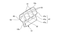
- the shaft clamping portion 12a includes a first plate-like portion 47 and a second plate-like portion 48 that face and hold the horizontal shaft portion 31 therebetween.
- the first plate-like portion 47 and the second plate-like portion 48 impart a rotational torque to the sun visor body 11 (see FIG. 7) by sandwiching the horizontal shaft portion 31.
- the first plate-like portion 47 faces rearward and the second plate-like portion 48 faces frontward.
- the first plate-like portion 47 has a plurality (three in this example) of divided pieces 47a.
- the plurality of divided pieces 47 a are arranged in the axial direction of the horizontal shaft portion 31 via a plurality of (in this example, two) slits 51.
- Each of the plurality of divided pieces 47 a is formed in a flat plate shape and includes a flat inner surface 52 that contacts the peripheral surface of the horizontal shaft portion 31.
- the split pieces 47a located at the left and right ends are provided at positions corresponding to the left and right flat portions 43 in the axial direction of the horizontal shaft portion 31, and the sun visor body 11 (see FIG. 7) is attached to the ceiling surface 41 (see FIG. 7).
- the planar inner surface 52 is aligned with the flat portion 43 to hold the position of the sun visor body 11 (see FIG. 7).
- the second plate-like portion 48 has no slit and is not divided.
- the second plate-like portion 48 is formed in a curved plate shape and includes a curved inner surface 53.
- the curved inner surface 53 is opposed to the planar inner surface 52 with the horizontal shaft portion 31 interposed therebetween, and is in contact with the peripheral surface of the horizontal shaft portion 31.
- the curved inner surface 53 does not contact the flat portion 43 of the horizontal shaft portion 31 in the process in which the sun visor body 11 (see FIG. 7) rotates between the retracted position and the maximum deployed position.
- the curved surface portion 45 can be contacted while covering.
- the curved inner surface 53 is preferably formed with a radius of curvature substantially the same as the radius of curvature of the peripheral surface of the horizontal shaft portion 31.
- FIG. 10 is a view for explaining the rotation range of the sun visor body 11.
- FIG. 10 shows the position of the sun visor main body 11 that is rotated downward by the rotation angle ⁇ from the storage position P1 on the ceiling surface 41 (the chain line indicated by the symbol P).
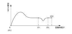
- FIG. 11 is a graph showing the characteristics of the rotation torque of the sun visor main body 11, the horizontal axis indicates the rotation angle ⁇ with the storage position P1 being 0 °, and the vertical axis indicates the rotation torque.
- FIG. 12 is a graph showing the characteristics of the rotational torque of the sun visor body 11 in a comparative example in which the curved surface portion 45 is not provided with an uneven portion, and is a graph corresponding to FIG.
- the turning torque begins to gradually decrease from the turning angle ⁇ 1 at which the curved inner surface 53 (see FIG. 10) begins to overlap the flat portion 43 (see FIG. 10).
- the rotational torque becomes the lowest.
- the rotation torque is recovered at the rotation angle ⁇ 2 at which the curved inner surface 53 exceeds the flat portion 43.
- the rotational torque is greatly reduced in the rotation region from the rotation angle ⁇ 1 to the rotation angle ⁇ 2.
- the contact area with the curved inner surface 53 is greatly reduced in the curved surface portion 45 having a small area sandwiched between the two flat portions 43. For this reason, in the rotation range from the rotation angle ⁇ 1 to the rotation angle ⁇ 2, there is a problem that the sun visor body 11 is not sufficiently held and hangs down due to vibration or the like.
- the rotational torque of the sun visor body 11 is also reduced in the rotational range (rotational angles ⁇ 1 to ⁇ 2) in which the contact area between the leaf spring 12 and the horizontal shaft portion 31 decreases. It is possible to obtain a substantially constant and stable rotational torque without being favorably maintained. As a result, the problem that the sun visor body 11 hangs down due to vibration or the like can be solved, and the sun visor body 11 can be reliably held at the use position.
- a large number of concave and convex portions 46 are provided on the curved surface portion 45 adjacent to the flat portion 43 in the axial direction of the horizontal shaft portion 31 (see FIG. 9).
- the present invention is not limited thereto, and a large number of uneven portions 66 may be provided in a portion excluding the flat portion 43 on the peripheral surface of the horizontal shaft portion 31 of the rotating shaft 30 including the flat portion 43.
- the basic configuration of the third embodiment is the same as that of the second embodiment.
- the range in which the uneven portion 66 is provided is a range G slightly longer than the axial length of the shaft clamping portion 12a, and the flat portion 43 is Except for this, the uneven portion 66 is provided on almost the entire circumference of the peripheral surface of the horizontal shaft portion 31.
- the axial length of the shaft clamping portion 12 a is substantially the same as the axial length range in which the flat portion 43 on the horizontal shaft portion 31 is provided. Therefore, in the state shown in FIGS. 13 and 14, the range in which the uneven portion 66 is provided in the axial direction is wider than the contact surface between the shaft holding portion 12 a and the horizontal shaft portion 31.
- the concavo-convex portion 66 In order to provide the concavo-convex portion 66 on almost the entire contact surface of the shaft clamping portion 12a and the horizontal shaft portion 31, and to make the concavo-convex portion 66 in which the lubricant accumulates on almost the entire contact surface, the concavo-convex portion 66 is at least What is necessary is just to be provided in the part except the flat part 43 of the surrounding surface of the rotating shaft 30 containing the flat part 43. FIG. However, the concavo-convex portion 66 may be provided in a wide range as shown in FIGS.
- the uneven portions 66 are provided as described above, the uneven portions 66 are provided on almost the entire contact surface between the shaft clamping portion 12 a and the horizontal shaft portion 31, and the lubricant is accumulated in the many uneven portions 66. Therefore, as already described in the first embodiment, even if the clamping pressure of the shaft clamping portion 12a is applied to the peripheral surface of the horizontal shaft portion 31, lubrication is performed from between the contact surfaces of the shaft clamping portion 12a and the horizontal shaft portion 31. Since the agent is prevented from being scattered, the lubrication performance between the contact surfaces can be maintained for a long time.
- the concavo-convex portion 66 also has an effect of increasing the friction coefficient.
- the uneven portion 66 is provided on almost the entire contact surface between the shaft clamping portion 12a and the horizontal shaft portion 31, if the uneven portion 66 has an appropriate depth or height, it is shown in FIG.
- the rotation torque of the sun visor body 11 in the entire rotation area from the storage position P1 of the ceiling surface 41 to the maximum deployment position P2 on the front window 42 side can be set to an appropriate magnitude. That is, according to the third embodiment, the rotation torque can be changed by selecting the depth or height of the concavo-convex portion 66, so that the rotation torque can be easily adjusted.
- the depth or height of the concavo-convex portion 66 is preferably set in the range of 20 ⁇ m to 40 ⁇ m, as already described in detail in the first and second embodiments. Further, as means for forming the uneven portion 66, similarly to the uneven portion 33 (see FIG. 3) described above, an arbitrary pattern is provided on the molding surface of the molding die, and this pattern is transferred to the surface of the molded product at the time of molding. The embossing process is suitable.
- the basic configuration of the fourth embodiment is the same as that of the first embodiment, the second embodiment, and the third embodiment.
- the difference is that the shaft clamping portion 12a of the leaf spring 12 is different as shown in FIG. This is the point that a through hole 55 is provided at the top of the.
- the overall shape of the leaf spring 12 shown in FIG. 15 is the overall shape of the leaf spring 12 of the second embodiment and the third embodiment, but the overall shape like the leaf spring 12 of the first embodiment. It may be.
- the leaf spring 12 has the pair of fixing leg pieces 12b of the leaf spring 12 attached to the bearing member 21 (see FIG. 1).
- a pair of fixing leg pieces 12b may be fitted (locked / engaged) to be press-fitted and fitted (locked / engaged) into the bearing member 21.
- the assembling procedure of the rotating shaft 30, the bearing member 21, and the leaf spring 12 is generally performed in the following procedure, although it depends on the structure of the bearing member 21 and the leaf spring 12. .
- the pair of fixing leg pieces 12b are fitted (locked and engaged), and then the lubricant is applied to the inside of the shaft holding portion 12a, and then the pair of fixing leg pieces 12b is attached to the bearing member 21.
- the leaf spring 12 is assembled to the bearing member 21 by press-fitting and fitting (locking and engaging). Thereafter, the horizontal shaft portion 31 of the rotating shaft 30 is inserted into the bearing portion 21 a of the bearing member 21 and the shaft clamping portion 12 a of the leaf spring 12.
- the through hole 55 is provided, the insufficient amount of lubricant can be additionally charged through the through hole 55 even after the horizontal shaft portion 31 is inserted (press-fitted) into the shaft holding portion 12a.
- the lubricant is The amount will be insufficient. Even in such a case, the insufficient amount of lubricant can be additionally charged through the through hole 55 while the rotating shaft 30 is attached to the leaf spring 12.
- the rotation shaft 30 is a solid shaft body made of synthetic resin.
- the rotation shaft according to the present invention is, for example, a combination of an alloy inner cylinder portion and a synthetic resin outer cylinder.
- a hollow shaft body or a shaft body formed by combining a plurality of members that can be divided in the axial direction may be used, and the structure of the rotating shaft is arbitrary as long as the uneven portion can be formed on the peripheral surface.
Landscapes
- Engineering & Computer Science (AREA)
- Mechanical Engineering (AREA)
- Pivots And Pivotal Connections (AREA)
Abstract
回動用シャフトと板ばねの接触面間の潤滑性能を長期に持続して、優れた操作性を維持し、しかも、異音の発生および回動トルクの低下を防止する車両用サンバイザを提供する。日除け機能を備えたサンバイザ本体を有する車両用サンバイザであって、サンバイザ本体を回動可能に支持する回動用シャフト30と、サンバイザ本体に設けられ、回動用シャフト30の周面に弾性的に嵌合してサンバイザ本体に回動トルクを付与する板ばね12と、回動用シャフト30と板ばね12の接触面間を潤滑するための潤滑剤と、を有する。回動用シャフト30の水平軸部31周面のうち、板ばね12と接触する面には、潤滑剤を保持可能な凹凸部33が形成される。
Description
本発明は、車両用サンバイザに関し、より詳細には、車両用サンバイザにおいて優れた操作性を長期に持続させる技術に関する。
通常、車両には、運転席および助手席それぞれの斜め上方に、日除けとしてのサンバイザが設けられている。従来、回動式の車両用サンバイザが各種提案されている(たとえば、特許文献1参照)。
図16は、特許文献1に記載される車両用サンバイザを説明する図であり、車両用サンバイザ100は、サンバイザ本体101を有する。サンバイザ本体101は、シェル構成体101Aとシェル構成体101Bからなる。シェル構成体101Aとシェル構成体101Bは、シェル構成体101Aの接合ピン102をシェル構成体101Bのボス孔103に嵌め合せることで接合される。接合されたサンバイザ本体101は、回動用シャフト104に回動可能に支持される。サンバイザ本体101には、回動用シャフト104に弾性的に嵌合される板ばね105が組み込まれており、この板ばね105は、回動用シャフト104を締め付けてサンバイザ本体101に回動トルク(回動抵抗)を付与する。サンバイザ本体101は、この回動トルクによって位置決めが可能になると共に、回動トルクに抗して回動操作されることで位置調整が可能になる。
ところで、サンバイザ本体の操作性を高めるため、回動用シャフトの周面に潤滑剤を塗布し、回動用シャフトと板ばねの接触面間の潤滑性能を向上させることが一般に行われている。この潤滑性能を持続させるには、回動用シャフトと板ばねの接触面間に十分な量の潤滑剤を常時介在させておく必要がある。
しかしながら、上述した車両用サンバイザ100において、回動用シャフト104に潤滑剤を用いた場合、回動用シャフト104の周面に加わる板ばね105の締め付け圧力によって、回動用シャフト104の周面から潤滑剤が散ってしまう。即ち締め付け圧力によって板ばね105と回動用シャフト104の間から潤滑剤が板ばね105外周にはみ出てしまう。このため、回動用シャフト104と板ばね105の接触面間の潤滑性能が低下し、異音が発生する不具合が生ずる。また、このような潤滑性能の低下に伴って回動用シャフト104が削れると、サンバイザ本体101の回動トルクが低下する問題も生ずる。
なお、特許文献1には、接合ピン102とボス孔103の接触面に凹凸部を形成することで、接合ピン102とボス孔103との間の摩擦抵抗を減らし、異音の発生を抑制する技術が開示されている。この技術は、シェル構成体101Aとシェル構成体101Bによる異音を抑制するための技術であり、特許文献1には、上述した潤滑性の問題を解消する技術については、開示されていない。
そこで、本発明は、このような事情に鑑みてなされたものであり、その目的は、回動用シャフトと板ばねの接触面間の潤滑性能を長期に持続して、優れた操作性を維持し、かつ、異音の発生および回動トルクの低下を防止する車両用サンバイザを提供することにある。
このような目的を達成するため、本発明は、以下の構成によって把握される。
(1)本発明の車両用サンバイザは、日除け機能を備えたサンバイザ本体を有する車両用サンバイザにおいて、前記サンバイザ本体を回動可能に支持する回動用シャフトと、前記サンバイザ本体に設けられ、前記回動用シャフトの周面に弾性的に嵌合して前記サンバイザ本体に回動トルクを付与する板ばねと、前記回動用シャフトと前記板ばねの接触面間を潤滑するための潤滑剤と、前記回動用シャフトの周面のうち前記板ばねと接触する面に設けられ、前記潤滑剤を保持可能な凹凸部と、を有することを特徴とする。
(1)本発明の車両用サンバイザは、日除け機能を備えたサンバイザ本体を有する車両用サンバイザにおいて、前記サンバイザ本体を回動可能に支持する回動用シャフトと、前記サンバイザ本体に設けられ、前記回動用シャフトの周面に弾性的に嵌合して前記サンバイザ本体に回動トルクを付与する板ばねと、前記回動用シャフトと前記板ばねの接触面間を潤滑するための潤滑剤と、前記回動用シャフトの周面のうち前記板ばねと接触する面に設けられ、前記潤滑剤を保持可能な凹凸部と、を有することを特徴とする。
この構成によれば、回動用シャフトの周面に設けられる凹凸部には、潤滑剤が保持されて溜まる。このため、板ばねの締め付け圧力が回動用シャフトの周面に加わっても、回動用シャフトの周面から潤滑剤が散ることを防ぐことができる。したがって、回動用シャフトと板ばね部材の接触面間にしっかりと潤滑剤を介在させることができ、回動用シャフトと板ばねの接触面間の潤滑性能を長期に持続することができる。
(2)上記(1)の構成において、前記周面には、平坦部が部分的に設けられ、前記板ばねは、平面状の内面と、前記平面状の内面に対向する曲面状の内面と、有し、前記平面状の内面は、前記サンバイザ本体が車室の天井面の格納位置にあるとき、前記平坦部に合わさって前記サンバイザ本体の位置を保持し、前記曲面状の内面は、前記サンバイザ本体が前記格納位置と使用位置の間で回動するとき、前記平坦部には接触せずに前記平坦部を覆いながら前記周面に接触し、前記平坦部に対して前記回動用シャフトの軸方向に隣接する前記周面の一部であって前記曲面状の内面に接触可能な曲面部に、前記凹凸部が設けられることを特徴とする。
この構成では、回動用シャフトの周面のうち平坦部に隣接する曲面部に、凹凸部を設けた。曲面部においては、平坦部が隣接するため、回動用シャフトの周面の他の面に比べ、板ばねの曲面状の内面に対して十分な接触面積が得られない。このため、仮に、凹凸部を曲面部に設けない場合、サンバイザ本体の回動トルクが低下し、使用位置においてサンバイザ本体が保持されずに振動などで垂れ下がってしまう不具合が生ずる。この点、本発明では、曲面部に凹凸部を設けたので、曲面部では、凹凸部によって摩擦係数が増加する。これにより、面積の小さい曲面部と板ばねの曲面状の内面とが接触するサンバイザ本体の回動域において、サンバイザ本体の回動トルクを高めることができる。結果、サンバイザ本体が保持されずに振動などで垂れ下がる不具合を解消でき、使用位置においてサンバイザ本体を確実に保持することができる。
(3)上記(2)の構成において、前記平坦部は、前記軸方向に沿って複数設けられ、前記曲面部は、隣り合う2つの前記平坦部の間に位置することを特徴とする。
この構成によれば、隣り合う2つの平坦部に挟まれる面積の小さい曲面部において、摩擦係数を増加することができる。
(4)上記(1)の構成において、前記周面には、平坦部が部分的に設けられ、前記板ばねは、平面状の内面と、前記平面状の内面に対向する曲面状の内面と、有し、前記平面状の内面は、前記サンバイザ本体が車室の天井面の格納位置にあるとき、前記平坦部に合わさって前記サンバイザ本体の位置を保持し、前記曲面状の内面は、前記サンバイザ本体が前記格納位置と使用位置の間で回動するとき、前記平坦部には接触せずに前記平坦部を覆いながら前記周面に接触し、前記凹凸部は、少なくとも前記平坦部を含む前記回動用シャフトの前記周面であって、前記平坦部を除く部分に設けられていることを特徴とする。
この構成では、シャフト挟持部と水平軸部の接触面のほぼ全面に凹凸部を設けているのでンバイザ本体の天井面の格納位置からフロントウインドウ側の最大展開位置に至る回動域全体の回動トルクを凹凸部の深さまたは高さを選択することで変えられるので適切な回動トルクに調整しやすい。
(5)上記(1)から(4)の構成において、前記回動用シャフトは、合成樹脂で成形される成形品であり、前記凹凸部は、シボ加工によって成形されることを特徴とする。
この構成によれば、シボ加工を用いることで、回動用シャフトの周面に凹凸部を容易に設けることができる。
(6)上記(1)~(5)の構成において、前記凹凸部の深さまたは高さは、20μm~40μmに設定されることを特徴とする。
この構成によれば、凹凸部の深さまたは高さを適正な範囲に設定し、潤滑性能を高めることができる。すなわち、凹凸部の深さまたは高さが20μmを下回ると、凹凸部に溜まる潤滑剤の量が不足し、要求される潤滑性能が得られないおそれがある。一方、凹凸部の深さまたは高さが40μmを上回る場合、耐久性を評価した試験において、回動用シャフトの周面が削れてしまう不具合が確認された。これは、凹凸部に溜まった潤滑剤によって初期は良好な潤滑性能が得られるものの、潤滑剤が徐々に減少して潤滑性能が低下していくと、凹凸部の深さまたは高さの影響が大きくなり、摩擦抵抗が増えるためであると考えられる。
本発明の車両用サンバイザによれば、回動用シャフトと板ばねの接触面間の潤滑性能を長期に持続することができる。よって、優れた操作性を維持できる共に、異音の発生を防ぎ、しかも、安定した回動トルクを得ることができる。
以下、添付図面を参照して、本発明を実施するための形態(以下、実施形態)について詳細に説明する。なお、実施形態の説明の全体を通して同じ要素には同じ番号を付している。また、実施形態および図中において、「前」、「後」、「左」、「右」、「上」、「下」は、各々、車両に乗車した乗員から見た方向を示す。
(第1実施形態)
第1実施形態の車両用サンバイザの全体構成を説明する。
図1は、車両用サンバイザの正面図であり、サンバイザ本体の一部を破断して内部構成を示す図である。図1に示すように、車両用サンバイザ10は、日除け機能を備えたサンバイザ本体11を有する。サンバイザ本体11は、運転席あるいは助手席の斜め上方位置において、車室の天井面に格納可能に設けられる。乗員は、サンバイザ本体11を回動操作して位置や向きを調整することで、フロントウインドウあるいはサイドウインドウからの直射日光などの眩惑を防ぐ。
第1実施形態の車両用サンバイザの全体構成を説明する。
図1は、車両用サンバイザの正面図であり、サンバイザ本体の一部を破断して内部構成を示す図である。図1に示すように、車両用サンバイザ10は、日除け機能を備えたサンバイザ本体11を有する。サンバイザ本体11は、運転席あるいは助手席の斜め上方位置において、車室の天井面に格納可能に設けられる。乗員は、サンバイザ本体11を回動操作して位置や向きを調整することで、フロントウインドウあるいはサイドウインドウからの直射日光などの眩惑を防ぐ。
以下、各部の構成を詳細に説明する。
車両用サンバイザ10は、サンバイザ本体11を回動可能に支持する回動用シャフト30と、サンバイザ本体11の内部に設けられる板ばね12と、回動用シャフト30を車体側に固定するためのブラケット13とから主に構成される。
車両用サンバイザ10は、サンバイザ本体11を回動可能に支持する回動用シャフト30と、サンバイザ本体11の内部に設けられる板ばね12と、回動用シャフト30を車体側に固定するためのブラケット13とから主に構成される。
サンバイザ本体11は、たとえば、サンバイザコア15と、サンバイザコア15の外表面を包むサンバイザ表皮16とからなる。サンバイザ本体11の中央部には、ミラーユニット17を設けてもよい。サンバイザコア15には、熱可塑性樹脂、熱可塑性樹脂に発泡剤を混ぜた樹脂、熱可塑性樹脂にゴム成分を混ぜた樹脂などの各種の材料が使用可能であるが、衝撃吸収機能の向上および軽量化を考えると、ポリプロピレンビーズ発泡成形体、ポリスチレンビーズ発泡成形体などのビーズ発泡成形体が好ましい。また、サンバイザ表皮16は、不織布シート、クロスシート、樹脂シートなど、クッション性を有する材料で構成されることが好ましい。また、必要に応じて、サンバイザコア15の内部にループ状のワイヤフレーム18を挿入してもよい。なお、ここでは、サンバイザコア15およびサンバイザ表皮16でサンバイザ本体11を構成したが、所定の剛性と日除け機能が得られる構造であれば、サンバイザ本体11の構成は任意である。
回動用シャフト30は、ほぼL字状に屈曲して形成され、水平軸部31および垂直軸部32を有する。水平軸部31は、左右方向に延びる軸部であり、サンバイザ本体11上部の左右一側(ここでは、左側)に挿入される。垂直軸部32は、水平軸部31の一端(ここでは、左側の端部)に屈曲部を介して連なり、ほぼ鉛直上向きに延びてブラケット13に挿入される。
板ばね12は、その弾性力によって、回動用シャフト30の水平軸部31に弾性的に嵌合される。サンバイザ本体11には、板ばね12の弾性力により、回動トルク(回動抵抗)が付与される。この回動抵抗により、サンバイザ本体11は、任意の回動位置で位置決めが可能となる。なお、回動用シャフト30および板ばね12のさらに詳しい構成については、後述する。
回動用シャフト30をサンバイザ本体11に連結させる手段は、格別に限定されるものではなく、周知の車両用サンバイザに用いられる各種の軸受構造から選択可能であり、種類は任意である。ここでは、合成樹脂製の軸受部材21をサンバイザ本体11の内部に設けた例を示す。
この軸受部材21は、正面視で上方に開放したほぼコの字状に形成され、たとえば、ポリアセタール樹脂、ポリアミド樹脂、ポリプロピレン樹脂など、汎用の合成樹脂を用いた射出成形により、所定の形状に成形される。軸受部材21は、所定の間隔で対向する円筒状の左右の軸受部21aを有し、これら左右の軸受部21aには、回動用シャフト30の水平軸部31の左右両端部が回動可能に嵌合される。これにより、サンバイザ本体11は、水平軸部31周りに回動可能となり、車室の天井面における格納位置と、フロントウインドウと平行面に展開される使用位置との間で位置調整が可能となる。
ブラケット13は、車体側に固定されると共に回動用シャフト30の垂直軸部32を回動可能に支持する。これにより、サンバイザ本体11は、垂直軸部32周りに回動可能となり、フロントウインドウとサイドウインドウとの間においても、位置調整が可能となる。
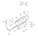
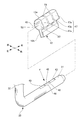
次に、板ばね12および回動用シャフト30の構成を図2、図3に基づいて詳細に説明する。図2は、図1に示される車両用サンバイザ10の構成から回動用シャフト30と板ばね12を抜き出して示した図である。図3は、図2の分解図である。
図2に示すように、板ばね12は、シャフト挟持部12aと、前後1対の固定用脚片12b(図では後側の固定用脚片12bのみを示す)とから構成される。シャフト挟持部12aは、所定の断面形状(たとえば、下方に開放したほぼU字状など)に形成され、水平軸部31に弾性的に接して嵌合され、水平軸部31の周面を締め付ける。1対の固定用脚片12bは、シャフト挟持部12aの下端に連なり、互いに対向するように延設される。このように構成される板ばね12は、左右の軸受部21a(図1参照)の間に配置され、1対の固定用脚片12bで軸受部材21(図1参照)を挟むようにして取り付けられている。
なお、この取り付けに関しては、1対の固定用脚片12bを軸受部材21に嵌合(係止、係合)する場合や1対の固定用脚片12bを嵌合(係止、係合)し軸受部材21に圧入、嵌合(係止、係合)する場合もある。
なお、この取り付けに関しては、1対の固定用脚片12bを軸受部材21に嵌合(係止、係合)する場合や1対の固定用脚片12bを嵌合(係止、係合)し軸受部材21に圧入、嵌合(係止、係合)する場合もある。
図3に示すように、回動用シャフト30は、水平軸部31および垂直軸部32が一体成形された成形品であり、たとえば、汎用の合成樹脂を用いた射出成形により成形される。回動用シャフト30に使用される樹脂材料は、たとえば、ポリアミド系樹脂、ポリエチレン系樹脂、ポリプロピレン系樹脂、ポリスチレン系樹脂、ポリエチレンテレフタレート系樹脂、ポリビニルアルコール系樹脂、塩化ビニル系樹脂、ポリアセタール系樹脂、ポリカーボネート系樹脂、アイオノマー系樹脂、アクリロニトリル/ブタジエン/スチレン(ABS)樹脂などから任意に選択可能である。さらに上記樹脂材料に任意の繊維材料(たとえば、ガラス繊維など)を混入して、回動用シャフト30の耐摩耗性を高めるようにしてもよい。
なお、回動用シャフト30の水平軸部31の断面形状は、車両用サンバイザ10に求められる機能性や操作性、回動トルクなどに応じて、円形や楕円形を含む各種の形状から選択される。
水平軸部31の周面とシャフト挟持部12aの内面の間には、グリスなどの任意の潤滑剤が介在される。そして、水平軸部31の周面のうちシャフト挟持部12aと接触する面には、潤滑剤を保持可能な多数の凹凸部33が設けられる。ここでは、シャフト挟持部12aの軸方向長さよりもやや長い範囲Bに凹凸部33を設けた例を示す。凹凸部33は、範囲Bにおいて、水平軸部31周面の軸方向および周方向に亘り、多数設けられる。
凹凸部33は、凹部と凸部によって構成される。凹凸部33は、たとえば、皮革模様や、梨地、砂目、布目、木目、岩目、幾何学模様など、各種の凹凸状の模様から選択可能である。凹凸部33を形成する手段としては、成形金型の成形面に任意の模様を付け、この模様を成形品の表面に成形時に転写させるシボ加工が好適である。
なお、図3において、範囲Cで示される屈曲部付近は、サンバイザ本体11(図1参照)やブラケット13によって覆われない露出部分(意匠面)である。この範囲Cにおいても、意匠面としての凹凸部35が設けられる。範囲Cの凹凸部35と範囲Bの凹凸部33は、同じ模様で形成してもよいし、または、互いに異なる模様で形成してもよい。
以上、説明した車両用サンバイザ10の作用・効果を図4に基づいて説明する。
図4に示すように、水平軸部31の範囲Bに設けられる多数の凹凸部33に潤滑剤36が溜まるため、シャフト挟持部12aの締め付け圧力が水平軸部31の周面に加わっても、シャフト挟持部12aと水平軸部31の接触面間から潤滑剤36が散ることが防止される。
図4に示すように、水平軸部31の範囲Bに設けられる多数の凹凸部33に潤滑剤36が溜まるため、シャフト挟持部12aの締め付け圧力が水平軸部31の周面に加わっても、シャフト挟持部12aと水平軸部31の接触面間から潤滑剤36が散ることが防止される。
これに対して、従来は、矢印(1)で示すように、シャフト挟持部12aの締め付け圧力によって、シャフト挟持部12aの端部から潤滑剤36が散ってしまう不具合があった。
この点、車両用サンバイザ10では、凹凸部33に潤滑剤36が溜まるため、水平軸部31とシャフト挟持部12aの接触面間に、潤滑剤36をしっかりと介在させることができ、シャフト挟持部12aと水平軸部31の接触面間の潤滑性能を長期に持続することができる。
よって、車両用サンバイザ10によれば、優れた操作性を維持できる共に、異音の発生を防ぎ、しかも、安定した回動トルクを得ることができる。
また、回動用シャフト30を合成樹脂で成形し、凹凸部33をシボ加工によって成形すれば、回動用シャフト30の周面に多数の凹凸部33を容易に設けることができる。
次に、凹凸部33の深さまたは高さの好適な大きさについて述べる。
本発明者等は、種々の研究開発を行い、図5に示される凹凸部33の深さ(または高さ)Dを適正な大きさに設定することにより、優れた潤滑性能を長期に持続させることに成功した。
本発明者等は、種々の研究開発を行い、図5に示される凹凸部33の深さ(または高さ)Dを適正な大きさに設定することにより、優れた潤滑性能を長期に持続させることに成功した。
すなわち、凹凸部33の深さDを20μmよりも小さく形成して、評価を実施したところ、凹凸部33に潤滑剤を十分に溜めることができず、要求される潤滑性能が十分に得られないことが分かった。
一方、凹凸部33の深さDを40μmよりも大きく形成して、回動用シャフト30の耐久性を評価したところ、回動用シャフト30の周面が削れてしまう不具合が確認された。これは、凹凸部33に溜まった潤滑剤によって初期は良好な潤滑性能が得られるものの、潤滑剤が徐々に減少して潤滑性能が低下すると、凹凸部33の深さの影響が大きくなり、摩擦抵抗が増える(回動用シャフト30が丸棒やすりのように作用する)ためであると考えられる。
以上より、凹凸部33の深さDは、20μm~40μmの範囲に設定されることが好適であり、この範囲に収まるように深さDを設定することによって、優れた潤滑性能を長期に持続できることを確認にした。なお、凹凸部33の深さ以外の寸法(凹部および凸部それぞれの外径や間隔等)は、凹凸部33に求められる機能あるいは潤滑剤の種類や粘度などに応じて、任意に設定される。
(第2実施形態)
次に、第2実施形態を図6~図11に基づいて説明する。なお、前述した第1実施形態と共通する要素には同じ符号を付して、重複する説明を省略することとする。
次に、第2実施形態を図6~図11に基づいて説明する。なお、前述した第1実施形態と共通する要素には同じ符号を付して、重複する説明を省略することとする。
前述した第1実施形態では、回動用シャフト30の水平軸部31において、範囲B(図3参照)の軸方向および周方向のほぼ全体に亘って凹凸部33を設けたが、本発明はこれに格別に限定されるものではなく、この他、シャフト挟持部12aと接触する水平軸部31の周面のうち、摩擦係数を増加させたい少なくとも一部の面に凹凸部を設けてもよい。
この第2実施形態では、図6および図7に示すように、前述した車両用サンバイザ10(図1参照)と同様に、サンバイザ本体11を回動用シャフト30で回動可能に支持し、回動用シャフト30の周面に板ばね12を弾性的に嵌合して、サンバイザ本体11に回動トルクを付与する。サンバイザ本体11は、回動用シャフト30を中心に、図7において矢印(2)で示す向きに回動操作されることで、車室の天井面41における格納位置と、フロントウインドウ42側の最大展開位置との間で使用位置が調整可能である。
図8に示すように、水平軸部31の周面には、サンバイザ本体11(図7参照)を天井面41(図7参照)の格納位置に保持する平坦部43が部分的に設けられる。この平坦部43は、水平軸部31の軸方向に沿って複数(この例では、2個)設けられる。さらに、図9に示すように、回動用シャフト30は、水平軸部31の周面の一部であって、平坦部43に対して水平軸部31の軸方向に隣接する曲面部45を有する。この例では、曲面部45は、隣り合う2つの平坦部43の間に位置する。そして、この曲面部45には、多数の凹凸部46が設けられる。
凹凸部46は、潤滑剤を保持可能であると共に、曲面部45の摩擦係数を増加させる作用をなす。凹凸部46を形成する手段としては、前述した凹凸部33(図3参照)と同様に、成形金型の成形面に任意の模様を付け、この模様を成形品の表面に成形時に転写させるシボ加工が好適である。また、曲面部45において適正な摩擦係数を得るためには、凹凸部46の深さまたは高さは、20μm以上が好適であり、たとえば、20μm~40μmの範囲から設定される。
図8に戻る。図8に示すように、板ばね12は、シャフト挟持部12aおよび固定用脚片12bから構成され、たとえば、鋼板などの金属板をプレス加工するなどして成形される。固定用脚片12bの形状は任意であるが、ここでは、シャフト挟持部12a側に開放するほぼコの字状に固定用脚片12bを形成する。また、サンバイザ本体11(図7参照)に固定用脚片12bを固定する手段は、各種の手段から選択可能であり、例えば、サンバイザ本体11(図7参照)に組み込まれ水平軸部31を支持する軸受部材(図示省略)に、固定用脚片12bを嵌合することで固定することができる。
シャフト挟持部12aは、所定の断面形状(たとえば、固定用脚片12b側に開放したほぼU字状など)に形成され、水平軸部31の周面に嵌合する。シャフト挟持部12aと水平軸部31の周面との間には、グリスなどの任意の潤滑剤が介在される。シャフト挟持部12aは、対向して水平軸部31を挟持する第1板状部47および第2板状部48を有する。これら第1板状部47および第2板状部48は、水平軸部31を挟持することでサンバイザ本体11(図7参照)に回動トルクを付与する。この例では、使用位置にあるサンバイザ本体11(図7参照)において、第1板状部47が後方に向き、第2板状部48が前方に向く。
第1板状部47は、複数(この例では、3個)の分割片47aを有する。これら複数の分割片47aは、複数(この例では、2本)のスリット51を介して水平軸部31の軸方向に並ぶ。複数の分割片47aのそれぞれは、平板状に形成されており、水平軸部31の周面に接触する平面状の内面52を備える。左右両端に位置する分割片47aは、水平軸部31の軸方向において、左右の平坦部43に対応する位置に設けられ、サンバイザ本体11(図7参照)が天井面41(図7参照)の格納位置にあるとき、平面状の内面52が平坦部43に合わさってサンバイザ本体11(図7参照)の位置を保持する。
一方、第2板状部48は、スリットを備えておらず、分割されていない形態である。第2板状部48は、曲板状に形成されており、曲面状の内面53を備える。この曲面状の内面53は、水平軸部31を挟んで平面状の内面52に対向し、かつ、水平軸部31の周面に接触する。曲面状の内面53は、サンバイザ本体11(図7参照)が格納位置と最大展開位置の間で回動する過程において、水平軸部31の平坦部43には接触せずに、平坦部43を覆いながら曲面部45に接触可能である。なお、曲面状の内面53は、水平軸部31の周面の曲率半径とほぼ同一の大きさの曲率半径で形成することが望ましい。
以上、説明した第2実施形態の車両用サンバイザ40の作用・効果を図10~図12に基づいて説明する。
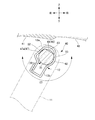
図10は、サンバイザ本体11の回動域を説明するための図である。図10では、天井面41における格納位置P1から、下方に回動角度θだけ回動させたサンバイザ本体11の位置(符号Pで示される一点鎖線)を示しており、サンバイザ本体11は、格納位置P1からフロントウインドウ42側の最大展開位置P2までの回動域を有する。図11は、サンバイザ本体11の回動トルクの特性を示すグラフであり、横軸が、格納位置P1を0°とする回動角度θを示し、縦軸が回動トルクを示す。
第2実施形態の車両用サンバイザ40では、図10および図11に示すように、格納位置P1からサンバイザ本体11を下方に回動した直後は、平坦部43を押える板ばね12(より具体的には、平面状の内面52)の保持力により、回動トルクがやや上昇するが、平面状の内面52が平坦部43から離れるに従って、回動トルクが適正な大きさに低下する。その後は、最大展開位置P2まで、ほぼ一定の安定した回動トルクが得られる。
ここで、仮に、曲面部45に凹凸部を設けない場合について考える。
図12は、曲面部45に凹凸部を設けない比較例におけるサンバイザ本体11の回動トルクの特性を示すグラフであり、図11に対応するグラフである。
図12は、曲面部45に凹凸部を設けない比較例におけるサンバイザ本体11の回動トルクの特性を示すグラフであり、図11に対応するグラフである。
図12に示すように、この比較例では、曲面状の内面53(図10参照)が平坦部43(図10参照)に重なり始める回動角度θ1から、回動トルクが徐々に低下し始め、曲面状の内面53が平坦部43に合わさると、回動トルクが最も低くなる。そして、曲面状の内面53が平坦部43を超える回動角度θ2で、回動トルクが回復する。このように、曲面部45に凹凸部を設けない場合、回動角度θ1から回動角度θ2の回動域において、回転トルクが大きく低下する。これは、2つの平坦部43に挟まれた面積の小さい曲面部45では、曲面状の内面53との接触面積が大幅に減少するからである。このため、回動角度θ1から回動角度θ2の回動域において、サンバイザ本体11が十分に保持されずに振動などで垂れ下がってしまう不具合が生ずる。
この点、第2実施形態の車両用サンバイザ40では、凹凸部46を曲面部45に設けたので、曲面部45では、凹凸部46により摩擦係数が増加する。これにより、板ばね12と水平軸部31との接触面積が減少する回動域(回動角度θ1~θ2)においても、図11に示したように、サンバイザ本体11の回動トルクが低下することなく良好に維持され、ほぼ一定の安定した回動トルクを得ることができる。結果、サンバイザ本体11が振動などで垂れ下がる不具合が解消でき、使用位置においてサンバイザ本体11を確実に保持することができる。
(第3実施形態)
次に、第3実施形態を図13および図14に基づいて説明する。なお、前述した第1実施形態および第2実施形態と共通する要素には同じ符号を付して、重複する説明を省略することとする。
次に、第3実施形態を図13および図14に基づいて説明する。なお、前述した第1実施形態および第2実施形態と共通する要素には同じ符号を付して、重複する説明を省略することとする。
前述した第2実施形態では、平坦部43に対して水平軸部31の軸方向に隣接する曲面部45に多数の凹凸部46を設けたが(図9参照)、本発明はこれに格別に限定されるものではなく、平坦部43を含む回動シャフト30の水平軸部31の周面の平坦部43を除く部分に多数の凹凸部66を設けてもよい。
図13に示すように、第3実施形態の基本的な構成は、第2実施形態と同じである。
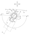
異なる点は、図13および図14に示すように、凹凸部66が設けられている範囲が、シャフト挟持部12aの軸方向長さよりもやや長い範囲Gとされており、また、平坦部43を除く、水平軸部31周面のほぼ全周に凹凸部66が設けられている点である。
異なる点は、図13および図14に示すように、凹凸部66が設けられている範囲が、シャフト挟持部12aの軸方向長さよりもやや長い範囲Gとされており、また、平坦部43を除く、水平軸部31周面のほぼ全周に凹凸部66が設けられている点である。
図6に示されるように、シャフト挟持部12aの軸方向長さは、水平軸部31上の平坦部43が設けられている軸方向長さの範囲と、ほぼ同じである。
従って、図13および図14に示される状態は、シャフト挟持部12aと水平軸部31の接触面よりも、凹凸部66を設ける範囲を軸方向に広くしている。
シャフト挟持部12aと水平軸部31の接触面のほぼ全面に凹凸部66を設け、接触面のほぼ全面に潤滑剤が溜まる凹凸部66があるようにするためには、凹凸部66は、少なくとも平坦部43を含む回動シャフト30の周面の平坦部43を除く部分に設けられていればよい。
しかしながら、余裕を見て図13および図14に示すような広い範囲に凹凸部66を設けるようにしてもよい。
従って、図13および図14に示される状態は、シャフト挟持部12aと水平軸部31の接触面よりも、凹凸部66を設ける範囲を軸方向に広くしている。
シャフト挟持部12aと水平軸部31の接触面のほぼ全面に凹凸部66を設け、接触面のほぼ全面に潤滑剤が溜まる凹凸部66があるようにするためには、凹凸部66は、少なくとも平坦部43を含む回動シャフト30の周面の平坦部43を除く部分に設けられていればよい。
しかしながら、余裕を見て図13および図14に示すような広い範囲に凹凸部66を設けるようにしてもよい。
このように凹凸部66が設けられると、シャフト挟持部12aと水平軸部31の接触面のほぼ全面に凹凸部66があり、多数の凹凸部66に潤滑剤が溜まる。
このことから、既に、第1実施形態で説明した通り、シャフト挟持部12aの締め付け圧力が水平軸部31の周面に加わっても、シャフト挟持部12aと水平軸部31の接触面間から潤滑剤が散ることが防止されるので、接触面間の潤滑性能を長期に維持することができる。
このことから、既に、第1実施形態で説明した通り、シャフト挟持部12aの締め付け圧力が水平軸部31の周面に加わっても、シャフト挟持部12aと水平軸部31の接触面間から潤滑剤が散ることが防止されるので、接触面間の潤滑性能を長期に維持することができる。
また、既に、第2実施形態で説明した通り、凹凸部66は摩擦係数を増加させる作用もある。
第3実施形態では、シャフト挟持部12aと水平軸部31の接触面のほぼ全面に凹凸部66を設けているので、その凹凸部66を適切な深さまたは高さとすれば、図10に示される天井面41の格納位置P1からフロントウインドウ42側の最大展開位置P2までの回動域全体のサンバイザ本体11の回動トルクを適切な大きさにすることができる。
つまり、この第3実施形態であれば、凹凸部66の深さまたは高さを選択することで回動トルクが変えられるので適切な回動トルクに調整しやすい。
第3実施形態では、シャフト挟持部12aと水平軸部31の接触面のほぼ全面に凹凸部66を設けているので、その凹凸部66を適切な深さまたは高さとすれば、図10に示される天井面41の格納位置P1からフロントウインドウ42側の最大展開位置P2までの回動域全体のサンバイザ本体11の回動トルクを適切な大きさにすることができる。
つまり、この第3実施形態であれば、凹凸部66の深さまたは高さを選択することで回動トルクが変えられるので適切な回動トルクに調整しやすい。
凹凸部66の深さまたは高さは、既に、第1実施形態および第2実施形態で詳細に説明した通り、20μm~40μmの範囲に設定されることが好適である。
また、凹凸部66を形成する手段としては、前述した凹凸部33(図3参照)と同様に、成形金型の成形面に任意の模様を付け、この模様を成形品の表面に成形時に転写させるシボ加工が好適である。
また、凹凸部66を形成する手段としては、前述した凹凸部33(図3参照)と同様に、成形金型の成形面に任意の模様を付け、この模様を成形品の表面に成形時に転写させるシボ加工が好適である。
(第4実施形態)
次に、第4実施形態を図15に基づいて説明する。なお、前述した第1実施形態、第2実施形態および第3実施形態と共通する要素には同じ符号を付して、重複する説明を省略することとする。
次に、第4実施形態を図15に基づいて説明する。なお、前述した第1実施形態、第2実施形態および第3実施形態と共通する要素には同じ符号を付して、重複する説明を省略することとする。
第4実施形態の基本的な構成は、第1実施形態、第2実施形態および第3実施形態と同じであり、異なる点は、図15に示されるように、板ばね12のシャフト挟持部12aの頂部に貫通孔55を設けた点である。
なお、図15に示される板ばね12の全体形状は、第2実施形態および第3実施形態の板ばね12の全体形状をしているが、第1実施形態の板ばね12のような全体形状であってもよい。
なお、図15に示される板ばね12の全体形状は、第2実施形態および第3実施形態の板ばね12の全体形状をしているが、第1実施形態の板ばね12のような全体形状であってもよい。
以下、この貫通孔55について説明する。
板ばね12は、前述したように、板ばね12の1対の固定用脚片12bが軸受部材21に取付けられる(図1参照)。
この取付方法として、例えば、1対の固定用脚片12bを嵌合(係止、係合)し軸受部材21に圧入、嵌合(係止、係合)するような場合がある。
板ばね12は、前述したように、板ばね12の1対の固定用脚片12bが軸受部材21に取付けられる(図1参照)。
この取付方法として、例えば、1対の固定用脚片12bを嵌合(係止、係合)し軸受部材21に圧入、嵌合(係止、係合)するような場合がある。
このような場合、回動シャフト30、軸受部材21および板ばね12の組付手順は、軸受部材21および板ばね12の構造にもよるが、一般的には、次のような手順で行われる。
先ず、1対の固定用脚片12bを嵌合(係止、係合)し、次にシャフト挟持部12aの内側に潤滑剤を塗布してから1対の固定用脚片12bを軸受部材21に圧入、嵌合(係止、係合)して、軸受部材21に板ばね12を組付けた状態とする。
その後、回動シャフト30の水平軸部31を軸受部材21の軸受部21aおよび板ばね12のシャフト挟持部12aに挿入する。
先ず、1対の固定用脚片12bを嵌合(係止、係合)し、次にシャフト挟持部12aの内側に潤滑剤を塗布してから1対の固定用脚片12bを軸受部材21に圧入、嵌合(係止、係合)して、軸受部材21に板ばね12を組付けた状態とする。
その後、回動シャフト30の水平軸部31を軸受部材21の軸受部21aおよび板ばね12のシャフト挟持部12aに挿入する。
上記手順では、1対の固定用脚片12bの嵌合を行った後に、水平軸部31をシャフト挟持部12aに挿入しているので、この挿入作業はシャフト挟持部12aの締め付け圧力を受けながら圧入する作業となる。
従って、水平軸部31とシャフト挟持部12aとの間には、隙間がほとんど無い状態で水平軸部31が挿入(圧入)されていくので、シャフト挟持部12aの内側に塗布しておいた潤滑剤が水平軸部31によって押し出され、潤滑剤の量が不足するような場合がある。
従って、水平軸部31とシャフト挟持部12aとの間には、隙間がほとんど無い状態で水平軸部31が挿入(圧入)されていくので、シャフト挟持部12aの内側に塗布しておいた潤滑剤が水平軸部31によって押し出され、潤滑剤の量が不足するような場合がある。
そこで、貫通孔55を設けておくと、水平軸部31をシャフト挟持部12aに挿入(圧入)した後でも、この貫通孔55を通して不足した分の潤滑剤を追加充填することができる。
また、上記とは別に、例えば、シャフト挟持部12aの内側に塗布した潤滑剤の量が少ない状態で回動シャフト30の板ばね12への組付け作業を行ってしまった場合にも潤滑剤の量が不足することになる。
このような場合でも、回動シャフト30を板ばね12に組付けた状態のままで、貫通孔55を通して不足分の潤滑剤を追加充填することができる。
このような場合でも、回動シャフト30を板ばね12に組付けた状態のままで、貫通孔55を通して不足分の潤滑剤を追加充填することができる。
以上、実施形態を用いて本発明を説明したが、本発明の技術的範囲は上記実施形態に記載の範囲には限定されないことは言うまでもない。上記実施形態に、多様な変更または改良を加えることが可能であることが当業者に明らかである。またその様な変更または改良を加えた形態も本発明の技術的範囲に含まれ得ることが、特許請求の範囲の記載から明らかである。
たとえば、実施形態では、回動用シャフト30を合成樹脂からなる中実の軸体としたが、本発明にかかる回動用シャフトは、たとえば、合金製の内筒部と合成樹脂製の外筒を組み合わせた中空の軸体や、軸方向に分割可能な複数の部材を組み合わせた軸体などでもよく、凹凸部を周面に形成することができれば、回動用シャフトの構成は任意である。
10 車両用サンバイザ
11 サンバイザ本体
12 板ばね
30 回動用シャフト
33 凹凸部
36 潤滑剤
40 車両用サンバイザ
41 天井面
43 平坦部
45 曲面部
46 凹凸部
52 平面状の内面
53 曲面状の内面
55 貫通孔
66 凹凸部
D 深さ(高さ)
11 サンバイザ本体
12 板ばね
30 回動用シャフト
33 凹凸部
36 潤滑剤
40 車両用サンバイザ
41 天井面
43 平坦部
45 曲面部
46 凹凸部
52 平面状の内面
53 曲面状の内面
55 貫通孔
66 凹凸部
D 深さ(高さ)
Claims (6)
- 日除け機能を備えたサンバイザ本体を有する車両用サンバイザにおいて、
前記サンバイザ本体を回動可能に支持する回動用シャフトと、
前記サンバイザ本体に設けられ、前記回動用シャフトの周面に弾性的に嵌合して前記サンバイザ本体に回動トルクを付与する板ばねと、
前記回動用シャフトと前記板ばねの接触面間を潤滑するための潤滑剤と、
前記回動用シャフトの周面のうち前記板ばねと接触する面に設けられ、前記潤滑剤を保持可能な凹凸部と、を有することを特徴とする車両用サンバイザ。 - 前記周面には、平坦部が部分的に設けられ、
前記板ばねは、平面状の内面と、前記平面状の内面に対向する曲面状の内面と、有し、
前記平面状の内面は、前記サンバイザ本体が車室の天井面の格納位置にあるとき、前記平坦部に合わさって前記サンバイザ本体の位置を保持し、
前記曲面状の内面は、前記サンバイザ本体が前記格納位置と使用位置の間で回動するとき、前記平坦部には接触せずに前記平坦部を覆いながら前記周面に接触し、
前記平坦部に対して前記回動用シャフトの軸方向に隣接する前記周面の一部であって前記曲面状の内面に接触可能な曲面部に、前記凹凸部が設けられることを特徴とする請求項1に記載の車両用サンバイザ。 - 前記平坦部は、前記軸方向に沿って複数設けられ、
前記曲面部は、隣り合う2つの前記平坦部の間に位置することを特徴とする請求項2に記載の車両用サンバイザ。 - 前記周面には、平坦部が部分的に設けられ、
前記板ばねは、平面状の内面と、前記平面状の内面に対向する曲面状の内面と、有し、
前記平面状の内面は、前記サンバイザ本体が車室の天井面の格納位置にあるとき、前記平坦部に合わさって前記サンバイザ本体の位置を保持し、
前記曲面状の内面は、前記サンバイザ本体が前記格納位置と使用位置の間で回動するとき、前記平坦部には接触せずに前記平坦部を覆いながら前記周面に接触し、
前記凹凸部は、少なくとも前記平坦部を含む前記回動用シャフトの前記周面であって、前記平坦部を除く部分に設けられていることを特徴とする請求項1に記載の車両用サンバイザ。 - 前記回動用シャフトは、合成樹脂で成形される成形品であり、
前記凹凸部は、シボ加工によって成形されることを特徴とする請求項1~4のいずれかに記載の車両用サンバイザ。 - 前記凹凸部の深さまたは高さは、20μm~40μmに設定されることを特徴とする請求項1~5のいずれかに記載の車両用サンバイザ。
Applications Claiming Priority (2)
| Application Number | Priority Date | Filing Date | Title |
|---|---|---|---|
| JP2013046650A JP6176605B2 (ja) | 2012-03-09 | 2013-03-08 | 車両用サンバイザ |
| JP2013-046650 | 2013-03-08 |
Publications (1)
| Publication Number | Publication Date |
|---|---|
| WO2014136293A1 true WO2014136293A1 (ja) | 2014-09-12 |
Family
ID=51492122
Family Applications (1)
| Application Number | Title | Priority Date | Filing Date |
|---|---|---|---|
| PCT/JP2013/072881 Ceased WO2014136293A1 (ja) | 2013-03-08 | 2013-08-27 | 車両用サンバイザ |
Country Status (2)
| Country | Link |
|---|---|
| JP (1) | JP6176605B2 (ja) |
| WO (1) | WO2014136293A1 (ja) |
Cited By (1)
| Publication number | Priority date | Publication date | Assignee | Title |
|---|---|---|---|---|
| CN108859687A (zh) * | 2018-08-13 | 2018-11-23 | 重庆华博汽车饰件有限公司 | 遮阳板回转轴 |
Families Citing this family (2)
| Publication number | Priority date | Publication date | Assignee | Title |
|---|---|---|---|---|
| JP6568899B2 (ja) * | 2017-06-26 | 2019-08-28 | 矢崎総業株式会社 | 車両用サンバイザ |
| CN114261264B (zh) * | 2021-11-16 | 2024-07-12 | 浙江汉工智能工业有限公司 | 一种便于润滑的遮阳板卡簧 |
Citations (3)
| Publication number | Priority date | Publication date | Assignee | Title |
|---|---|---|---|---|
| JPS5068157U (ja) * | 1973-10-26 | 1975-06-18 | ||
| JPH05286362A (ja) * | 1992-04-14 | 1993-11-02 | Neox Lab:Kk | 車両用サンバイザ |
| JP2011126349A (ja) * | 2009-12-16 | 2011-06-30 | Kasai Kogyo Co Ltd | 車両用サンバイザーの取付構造 |
-
2013
- 2013-03-08 JP JP2013046650A patent/JP6176605B2/ja active Active
- 2013-08-27 WO PCT/JP2013/072881 patent/WO2014136293A1/ja not_active Ceased
Patent Citations (3)
| Publication number | Priority date | Publication date | Assignee | Title |
|---|---|---|---|---|
| JPS5068157U (ja) * | 1973-10-26 | 1975-06-18 | ||
| JPH05286362A (ja) * | 1992-04-14 | 1993-11-02 | Neox Lab:Kk | 車両用サンバイザ |
| JP2011126349A (ja) * | 2009-12-16 | 2011-06-30 | Kasai Kogyo Co Ltd | 車両用サンバイザーの取付構造 |
Cited By (2)
| Publication number | Priority date | Publication date | Assignee | Title |
|---|---|---|---|---|
| CN108859687A (zh) * | 2018-08-13 | 2018-11-23 | 重庆华博汽车饰件有限公司 | 遮阳板回转轴 |
| CN108859687B (zh) * | 2018-08-13 | 2023-10-27 | 重庆华博汽车饰件有限公司 | 遮阳板回转轴 |
Also Published As
| Publication number | Publication date |
|---|---|
| JP2013212830A (ja) | 2013-10-17 |
| JP6176605B2 (ja) | 2017-08-09 |
Similar Documents
| Publication | Publication Date | Title |
|---|---|---|
| JP4935080B2 (ja) | ブッシュ軸受及びそれを用いた自動車のラック−ピニオン式操舵装置 | |
| CN102939022B (zh) | 针对护罩的防雾片安装结构 | |
| KR101560589B1 (ko) | 차량 시트용 피팅 | |
| CN104806634A (zh) | 衬套轴承的结构 | |
| US20150258925A1 (en) | Device for assembling rear seat back assembly | |
| JP6176605B2 (ja) | 車両用サンバイザ | |
| CN102189961A (zh) | 车辆用外侧镜装置 | |
| US20160061256A1 (en) | Synthetic resin-made sliding bearing | |
| CN108454357B (zh) | 用于车辆的遮阳板 | |
| JP5119317B2 (ja) | 特に接続モジュールと車両間の軸受接続としての、エラストマ金属軸受のためのエラストマ金属要素 | |
| JP2016121798A (ja) | オートテンショナ | |
| KR20160135130A (ko) | 힌지 장치 | |
| JP2011148347A (ja) | スタビライザブッシュ | |
| WO1998046440A1 (en) | Visor torque control | |
| JP5888516B2 (ja) | 車両用サンバイザ | |
| JP2006218884A (ja) | 車両用サンバイザ | |
| KR101500442B1 (ko) | 슬립부시 | |
| FR2833054A1 (fr) | Dispositif d'absorption d'energie cinetique a resistance elastique et a flambage, et application | |
| JP4729724B2 (ja) | 車両用サンバイザ構造 | |
| JP2015038366A (ja) | トーショナルダンパ | |
| JP5975485B2 (ja) | 自動車用パンタグラフ式ジャッキ | |
| JP2008087206A (ja) | 合成樹脂成形品のヒンジ部の構造 | |
| JP4911778B2 (ja) | スタビライザの軸受装置 | |
| KR102389459B1 (ko) | 차량용 시트 회전장치 | |
| JP5507993B2 (ja) | 車両用サンバイザーの取付構造 |
Legal Events
| Date | Code | Title | Description |
|---|---|---|---|
| 121 | Ep: the epo has been informed by wipo that ep was designated in this application |
Ref document number: 13876831 Country of ref document: EP Kind code of ref document: A1 |
|
| DPE1 | Request for preliminary examination filed after expiration of 19th month from priority date (pct application filed from 20040101) | ||
| NENP | Non-entry into the national phase |
Ref country code: DE |
|
| 122 | Ep: pct application non-entry in european phase |
Ref document number: 13876831 Country of ref document: EP Kind code of ref document: A1 |