WO2014136164A1 - アクチュエータおよびこれを備えた精密機械 - Google Patents
アクチュエータおよびこれを備えた精密機械 Download PDFInfo
- Publication number
- WO2014136164A1 WO2014136164A1 PCT/JP2013/007296 JP2013007296W WO2014136164A1 WO 2014136164 A1 WO2014136164 A1 WO 2014136164A1 JP 2013007296 W JP2013007296 W JP 2013007296W WO 2014136164 A1 WO2014136164 A1 WO 2014136164A1
- Authority
- WO
- WIPO (PCT)
- Prior art keywords
- drive belt
- actuator
- sliders
- slider
- guide rail
- Prior art date
- Legal status (The legal status is an assumption and is not a legal conclusion. Google has not performed a legal analysis and makes no representation as to the accuracy of the status listed.)
- Ceased
Links
Images


Classifications
-
- F—MECHANICAL ENGINEERING; LIGHTING; HEATING; WEAPONS; BLASTING
- F16—ENGINEERING ELEMENTS AND UNITS; GENERAL MEASURES FOR PRODUCING AND MAINTAINING EFFECTIVE FUNCTIONING OF MACHINES OR INSTALLATIONS; THERMAL INSULATION IN GENERAL
- F16H—GEARING
- F16H19/00—Gearings comprising essentially only toothed gears or friction members and not capable of conveying indefinitely-continuing rotary motion
- F16H19/02—Gearings comprising essentially only toothed gears or friction members and not capable of conveying indefinitely-continuing rotary motion for interconverting rotary or oscillating motion and reciprocating motion
- F16H19/06—Gearings comprising essentially only toothed gears or friction members and not capable of conveying indefinitely-continuing rotary motion for interconverting rotary or oscillating motion and reciprocating motion comprising flexible members, e.g. an endless flexible member
-
- F—MECHANICAL ENGINEERING; LIGHTING; HEATING; WEAPONS; BLASTING
- F16—ENGINEERING ELEMENTS AND UNITS; GENERAL MEASURES FOR PRODUCING AND MAINTAINING EFFECTIVE FUNCTIONING OF MACHINES OR INSTALLATIONS; THERMAL INSULATION IN GENERAL
- F16C—SHAFTS; FLEXIBLE SHAFTS; ELEMENTS OR CRANKSHAFT MECHANISMS; ROTARY BODIES OTHER THAN GEARING ELEMENTS; BEARINGS
- F16C29/00—Bearings for parts moving only linearly
- F16C29/008—Systems with a plurality of bearings, e.g. four carriages supporting a slide on two parallel rails
-
- F—MECHANICAL ENGINEERING; LIGHTING; HEATING; WEAPONS; BLASTING
- F16—ENGINEERING ELEMENTS AND UNITS; GENERAL MEASURES FOR PRODUCING AND MAINTAINING EFFECTIVE FUNCTIONING OF MACHINES OR INSTALLATIONS; THERMAL INSULATION IN GENERAL
- F16C—SHAFTS; FLEXIBLE SHAFTS; ELEMENTS OR CRANKSHAFT MECHANISMS; ROTARY BODIES OTHER THAN GEARING ELEMENTS; BEARINGS
- F16C29/00—Bearings for parts moving only linearly
- F16C29/02—Sliding-contact bearings
- F16C29/025—Hydrostatic or aerostatic
-
- F—MECHANICAL ENGINEERING; LIGHTING; HEATING; WEAPONS; BLASTING
- F16—ENGINEERING ELEMENTS AND UNITS; GENERAL MEASURES FOR PRODUCING AND MAINTAINING EFFECTIVE FUNCTIONING OF MACHINES OR INSTALLATIONS; THERMAL INSULATION IN GENERAL
- F16C—SHAFTS; FLEXIBLE SHAFTS; ELEMENTS OR CRANKSHAFT MECHANISMS; ROTARY BODIES OTHER THAN GEARING ELEMENTS; BEARINGS
- F16C32/00—Bearings not otherwise provided for
- F16C32/06—Bearings not otherwise provided for with moving member supported by a fluid cushion formed, at least to a large extent, otherwise than by movement of the shaft, e.g. hydrostatic air-cushion bearings
- F16C32/0603—Bearings not otherwise provided for with moving member supported by a fluid cushion formed, at least to a large extent, otherwise than by movement of the shaft, e.g. hydrostatic air-cushion bearings supported by a gas cushion, e.g. an air cushion
- F16C32/0614—Bearings not otherwise provided for with moving member supported by a fluid cushion formed, at least to a large extent, otherwise than by movement of the shaft, e.g. hydrostatic air-cushion bearings supported by a gas cushion, e.g. an air cushion the gas being supplied under pressure, e.g. aerostatic bearings
-
- F—MECHANICAL ENGINEERING; LIGHTING; HEATING; WEAPONS; BLASTING
- F16—ENGINEERING ELEMENTS AND UNITS; GENERAL MEASURES FOR PRODUCING AND MAINTAINING EFFECTIVE FUNCTIONING OF MACHINES OR INSTALLATIONS; THERMAL INSULATION IN GENERAL
- F16H—GEARING
- F16H19/00—Gearings comprising essentially only toothed gears or friction members and not capable of conveying indefinitely-continuing rotary motion
- F16H19/02—Gearings comprising essentially only toothed gears or friction members and not capable of conveying indefinitely-continuing rotary motion for interconverting rotary or oscillating motion and reciprocating motion
- F16H19/06—Gearings comprising essentially only toothed gears or friction members and not capable of conveying indefinitely-continuing rotary motion for interconverting rotary or oscillating motion and reciprocating motion comprising flexible members, e.g. an endless flexible member
- F16H2019/0681—Gearings comprising essentially only toothed gears or friction members and not capable of conveying indefinitely-continuing rotary motion for interconverting rotary or oscillating motion and reciprocating motion comprising flexible members, e.g. an endless flexible member the flexible member forming a closed loop
- F16H2019/0686—Gearings comprising essentially only toothed gears or friction members and not capable of conveying indefinitely-continuing rotary motion for interconverting rotary or oscillating motion and reciprocating motion comprising flexible members, e.g. an endless flexible member the flexible member forming a closed loop the flexible member being directly driven by a pulley or chain wheel
Definitions
- the present invention relates to an actuator including a slider that reciprocates along a guide rail by belt driving.
- an endless belt that is arranged between a pulley having a rotating shaft that extends downward is provided with a main bearing and a counter, in which a guide rail having a circular cross section and a counter guide rail are arranged in parallel.
- Each of the bearings is fixed using a plate-like fixture.
- the actuator includes two main bearings and one counter bearing, the two main bearings are held in a housing at a predetermined interval, and the housing is between the main bearings.
- the counter bearing is disposed at a position facing the recess.
- the endless belt is fixed to the inside of the concave portion of the housing for the main bearing and the position facing the concave portion of the counter bearing by using a plate-like fixture.
- the guide rail for the main bearing has a concave cross-sectional shape (the cross-section of the guide rail is U-shaped), and an endless belt is disposed in the concave portion of the guide rail.
- both ends of a fixture that is bent so that the center is lowered by one step are fixed to the left and right top plates of the main bearing.
- a pair of counter bearings are disposed above the top plates of the main bearings, and both ends of a fixture similar to that for the main bearings are fixed on both counter bearings.
- the endless belt is being fixed to the center part (the part arrange
- An object of the present invention is to improve the workability of maintenance of a drive belt in an actuator having a slider that reciprocates along a guide rail by belt driving.
- an actuator includes the following elements (1) to (4) and satisfies the following requirement (5).
- Two guide rails arranged in parallel on both sides of the drive belt in the width direction.
- a connecting plate in which the two sliders are fixed at a predetermined interval, and the drive belt is fixed between the two sliders.
- the drive belt is disposed at or near the center of gravity of the two sliders, and the connecting portion between the drive belt and the slider is between the two sliders of the connecting plate being fixed. Only part.
- the actuator according to one aspect of the present invention is characterized in that the actuator having the elements (1) to (4) satisfies the requirement (5).
- the drive belt, the slider, and the guide rail are arranged in parallel, and the connecting portion between the drive belt and the slider is only a portion between the two sliders of the connecting plate.
- the drive belt can be easily replaced by removing the drive belt from the connecting plate. Further, the alignment adjustment of the exchanged and attached drive belt can be performed from the opposite side of the connecting plate. Therefore, the maintenance workability of the drive belt is improved as compared with an actuator having two places where the drive belt and the slider are coupled.
- the actuator of this aspect can have a cover that can be attached and detached from the opposite side of the connecting plate as a cover that covers the drive belt.
- the guide rail has a concave cross-sectional shape
- the slider has a static pressure pad that forms a static pressure air bearing with the guide rail.
- the actuator of one embodiment of the present invention can be suitably used as a linear guide actuator for precision machines (precision machining machines, precision inspection devices, precision scanning devices, semiconductor device manufacturing devices, flat panel display manufacturing devices, etc.).
- the maintenance workability of the drive belt can be improved as compared with the conventional actuator.
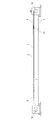
- FIG. 2 is a cross-sectional view taken along the line AA in FIG.
- FIG. 3 is a cross-sectional view taken along the line BB in FIG.
- the actuator of this embodiment includes an endless drive belt 1, two guide rails 2, two sliders 3, a connecting plate 4, a driven pulley 51, a drive The pulley 52 and the motor 6 that rotationally drives the drive pulley 52 are configured.
- the drive belt 1 is stretched between a driven pulley 51 and a drive pulley 52.
- the guide rail 2 includes a pair of side members 21 and a bottom plate portion 22 that face each other, and has a concave cross-sectional shape that is open on the upper side.
- the slider 3 includes an upper plate 31 disposed above the guide rail 2, a bottom plate 32 disposed below the bottom plate portion 22 of the guide rail 2, and each side member of the guide rail 2.
- 21 is composed of a pair of side plates 33 and 34 disposed outside. And both ends of the lower surface of the upper plate 31 (positions facing the upper surface of each side member 21 of the guide rail 2), both ends of the upper surface of the bottom plate 32 (positions facing the upper surface of each side member 21 of the guide rail 2) Static pressure pads 31a to 34a formed of graphite porous are respectively disposed on the upper and lower portions of the inner surfaces of the pair of side plates 33 and 34. Between these static pressure pads 31a to 34a and each side member 21 of the guide rail 2, a static pressure air bearing is formed.
- a fixing tool 41 for fixing the drive belt 1 is fixed to the center of the connecting plate 4 in the width direction by a bolt 42 (see FIG. 1).
- the fixing device 41 includes a base end portion 41a fixed to the connecting plate 4 and a receiving portion 41b having a recess into which the drive belt 1 is inserted, and bolts 43 having both ends in the width direction inserted from the receiving portion 41b side. (See FIG. 3).
- the upper plates 31 of the two sliders 3 are fixed by bolts 44 (see FIG. 1) on both sides of the connecting plate 4 with the fixture 41 interposed therebetween.
- This actuator is used with a load 71 and a balance weight 72 fixed to the outside in the width direction of the two sliders 3 coupled by the connecting plate 4.
- a center C1 of the drive belt 1 exists on a line L connecting the center of gravity C71 of the mounted object 71 and the center of gravity C72 of the balance weight 72. Therefore, the drive belt 1 is disposed at the center of gravity of the two sliders 3. Further, the connecting portion between the driving belt 1 and the slider 3 is only a portion between the two sliders 3 of the connecting plate 4 fixed.
- the driving belt 1 when the driving pulley 52 is rotated by driving the motor 6, the driving belt 1 is driven and guided by the driven pulley 51. As a result, the driving force of the driving belt 1 is transmitted to the two sliders 3 via the connecting plate 4, and the two sliders 3 reciprocate along the guide rails 2 together.
- the drive belt 1 can be easily replaced by removing the drive belt 1 from the fixture 41 of the connecting plate 4. Further, the alignment adjustment of the drive belt 1 that is exchanged and attached to the fixture 41 can be performed from the opposite side of the connecting plate 41 with the bolt 43 loosened. Therefore, the maintenance workability of the drive belt is improved as compared with an actuator having two places where the drive belt and the slider are coupled.
- the drive belt 1 since the drive belt 1 is disposed at the center of gravity of the two sliders 3, the resistance of the slider 3 to high acceleration / deceleration increases. Further, the drive belt 1 can be covered with a cover 8 that can be detached from the opposite side of the connecting plate 4. By covering the drive belt 1 with the cover 8, it is possible to reduce dust generation due to the abrasion powder of the drive belt 1.
Landscapes
- Engineering & Computer Science (AREA)
- General Engineering & Computer Science (AREA)
- Mechanical Engineering (AREA)
- Transmission Devices (AREA)
- Magnetic Bearings And Hydrostatic Bearings (AREA)
- Bearings For Parts Moving Linearly (AREA)
Abstract
この発明のアクチュエータでは、駆動ベルト(1)の幅方向両側に二本のガイドレール(2)が並列に配置されている。二本のガイドレール(2)に沿って往復運動する二個のスライダ(3)が、所定間隔を開けて連結板(4)に固定されている。連結板(4)の二個のスライダ(3)の間に駆動ベルト(1)が固定されている。駆動ベルト(1)と2個のスライダ(3)との結合箇所は、連結板(4)の二個のスライダ(3)が固定されている間の部分だけである。
Description
この発明は、ベルト駆動でガイドレールに沿って往復運動するスライダを備えたアクチュエータに関する。
従来より、高精度な製造装置、検査装置、搬送装置等では、回転モータによるベルト駆動で、スライダがガイドレールに沿って往復運動するアクチュエータが使用されている。このアクチュエータを構成するスライダはガイドレールに対する軸受を備えている。 このようなアクチュエータの従来例としては、特許文献1および2に記載されたものが挙げられる。
特許文献1および2に記載されたアクチュエータは、別々のガイドレールに沿って移動する主軸受(搭載物を固定するスライダ)とカウンタ軸受(スライダ)を有している。これらの軸受は、各ガイドレールとの間に静圧空気軸受を形成する静圧パッドを有する。特許文献1および2には、主軸受とカウンタ軸受とを逆方向に移動させることにより、加速時又は減速時などに生じる主軸受の反力が抑えられて、振動の抑制を図ることができると記載されている。
特許文献1および2に記載されたアクチュエータは、別々のガイドレールに沿って移動する主軸受(搭載物を固定するスライダ)とカウンタ軸受(スライダ)を有している。これらの軸受は、各ガイドレールとの間に静圧空気軸受を形成する静圧パッドを有する。特許文献1および2には、主軸受とカウンタ軸受とを逆方向に移動させることにより、加速時又は減速時などに生じる主軸受の反力が抑えられて、振動の抑制を図ることができると記載されている。
特許文献1に記載されたアクチュエータの一例では、断面が円形のガイドレールおよびカウンタガイドレールが並列に配置され、下向きに延びる回転軸を有するプーリ間に掛け渡された無端ベルトが、主軸受とカウンタ軸受にそれぞれ板片状の固定具を用いて固定されている。
特許文献1に記載されたアクチュエータの別の例では、アクチュエータが二個の主軸受と一個のカウンタ軸受を備え、二個の主軸受は所定間隔を開けてハウジングに保持され、ハウジングは主軸受間に凹部を有し、この凹部に対向する位置にカウンタ軸受が配置されている。無端ベルトは、主軸受用のハウジングの凹部内と、カウンタ軸受の前記凹部と対向する位置に、それぞれ板片状の固定具を用いて固定されている。
特許文献1に記載されたアクチュエータの別の例では、アクチュエータが二個の主軸受と一個のカウンタ軸受を備え、二個の主軸受は所定間隔を開けてハウジングに保持され、ハウジングは主軸受間に凹部を有し、この凹部に対向する位置にカウンタ軸受が配置されている。無端ベルトは、主軸受用のハウジングの凹部内と、カウンタ軸受の前記凹部と対向する位置に、それぞれ板片状の固定具を用いて固定されている。
特許文献2に記載されたアクチュエータでは、主軸受用のガイドレールが凹状の断面形状を有し(ガイドレールの断面がコ字形状であり)、ガイドレールの凹部内に無端ベルトが配置されている。
特許文献2に実施形態として記載されたアクチュエータの例では、主軸受の左右の頂板に、中央が一段低くなるように折り曲げられた固定具の両端が固定されている。また、一対のカウンタ軸受が主軸受の各頂板の上方に配置され、主軸受用と同様の固定具の両端が両カウンタ軸受の上に固定されている。そして、両固定具の中央部(両端より低く、ガイドレールの凹部と左右のカウンタ軸受間に配置される部分)に、無端ベルトが固定されている。
特許文献2に実施形態として記載されたアクチュエータの例では、主軸受の左右の頂板に、中央が一段低くなるように折り曲げられた固定具の両端が固定されている。また、一対のカウンタ軸受が主軸受の各頂板の上方に配置され、主軸受用と同様の固定具の両端が両カウンタ軸受の上に固定されている。そして、両固定具の中央部(両端より低く、ガイドレールの凹部と左右のカウンタ軸受間に配置される部分)に、無端ベルトが固定されている。
特許文献1および2に記載されたアクチュエータでは、前述のように、駆動ベルトとスライダ(主軸受とカウンタ軸受)およびガイドレールとが近接し、駆動ベルトとスライダとの結合箇所を二箇所有する。そのため、特許文献1および2に記載されたアクチュエータには、駆動ベルトのメンテナンス(交換や交換後のアライメント調整など)の作業性という点で改善の余地ある。
この発明の課題は、ベルト駆動でガイドレールに沿って往復運動するスライダを備えたアクチュエータにおいて、駆動ベルトのメンテナンスの作業性を改善することである。
この発明の課題は、ベルト駆動でガイドレールに沿って往復運動するスライダを備えたアクチュエータにおいて、駆動ベルトのメンテナンスの作業性を改善することである。
上記課題を解決するために、この発明の一態様のアクチュエータは、下記の要素(1) ~(4) を有し、下記の要件(5) を満たす。
(1) 駆動プーリと従動プーリとの間に掛け渡された駆動ベルト。
(2) 前記駆動ベルトの幅方向両側に並列に配置された二本のガイドレール。
(3) 前記駆動ベルトの駆動により、前記各ガイドレールに沿って往復運動する二個のスライダ。
(4) 前記二個のスライダが所定間隔を開けて固定され、前記二個のスライダ間に前記駆動ベルトが固定されている連結板。
(5) 前記駆動ベルトは、前記二個のスライダの重心位置またはその近傍に配置され、前記駆動ベルトと前記スライダとの結合箇所は、前記連結板の二個のスライダが固定されている間の部分だけである。
(1) 駆動プーリと従動プーリとの間に掛け渡された駆動ベルト。
(2) 前記駆動ベルトの幅方向両側に並列に配置された二本のガイドレール。
(3) 前記駆動ベルトの駆動により、前記各ガイドレールに沿って往復運動する二個のスライダ。
(4) 前記二個のスライダが所定間隔を開けて固定され、前記二個のスライダ間に前記駆動ベルトが固定されている連結板。
(5) 前記駆動ベルトは、前記二個のスライダの重心位置またはその近傍に配置され、前記駆動ベルトと前記スライダとの結合箇所は、前記連結板の二個のスライダが固定されている間の部分だけである。
すなわち、この発明の一態様のアクチュエータは、前記要素(1) ~(4) を有するアクチュエータにおいて、前記要件(5) を満たすことを特徴とする。
この態様のアクチュエータによれば、駆動ベルトとスライダおよびガイドレールが並列に配置され、前記駆動ベルトとスライダとの結合箇所は連結板の二個のスライダが固定されている間の部分だけであるため、駆動ベルトの交換は駆動ベルトを連結板から外すことで簡単に行うことができる。
また、交換されて取り付けられた駆動ベルトのアライメント調整は、連結板の反対側から行うことができる。よって、駆動ベルトとスライダとの結合箇所を二箇所有するアクチュエータと比較して、駆動ベルトのメンテナンスの作業性が改善される。
この態様のアクチュエータは、前記駆動ベルトを覆うカバーとして、前記連結板の反対側から着脱可能なカバーを有することができる。
この態様のアクチュエータにおいて、前記ガイドレールは凹状の断面形状を有し、前記スライダは、前記ガイドレールとの間に静圧空気軸受を形成する静圧パッドを有するものが好ましい。
この発明の一態様のアクチュエータは、精密機械(精密加工機械、精密検査装置、精密スキャン装置、半導体デバイス製造装置、フラットパネルディスプレイ製造装置など)の直線案内アクチュエータとして好適に使用できる。
この態様のアクチュエータによれば、駆動ベルトとスライダおよびガイドレールが並列に配置され、前記駆動ベルトとスライダとの結合箇所は連結板の二個のスライダが固定されている間の部分だけであるため、駆動ベルトの交換は駆動ベルトを連結板から外すことで簡単に行うことができる。
また、交換されて取り付けられた駆動ベルトのアライメント調整は、連結板の反対側から行うことができる。よって、駆動ベルトとスライダとの結合箇所を二箇所有するアクチュエータと比較して、駆動ベルトのメンテナンスの作業性が改善される。
この態様のアクチュエータは、前記駆動ベルトを覆うカバーとして、前記連結板の反対側から着脱可能なカバーを有することができる。
この態様のアクチュエータにおいて、前記ガイドレールは凹状の断面形状を有し、前記スライダは、前記ガイドレールとの間に静圧空気軸受を形成する静圧パッドを有するものが好ましい。
この発明の一態様のアクチュエータは、精密機械(精密加工機械、精密検査装置、精密スキャン装置、半導体デバイス製造装置、フラットパネルディスプレイ製造装置など)の直線案内アクチュエータとして好適に使用できる。
この発明のアクチュエータによれば、従来のアクチュエータと比較して駆動ベルトのメンテナンスの作業性を改善することができる。
以下、この発明の実施形態について説明するが、この発明はこの実施形態に限定されるものではない。
この実施形態のアクチュエータは、図1~3に示すように、無端状の駆動ベルト1と、二個のガイドレール2と、二個のスライダ3と、連結板4と、従動プーリ51と、駆動プーリ52と、駆動プーリ52を回転駆動するモータ6とで構成されている。駆動ベルト1は、従動プーリ51と駆動プーリ52との間に掛け渡されている。ガイドレール2は、対向する一対の側部材21と底板部22とからなり、上側が開放された凹状の断面形状を有する。
この実施形態のアクチュエータは、図1~3に示すように、無端状の駆動ベルト1と、二個のガイドレール2と、二個のスライダ3と、連結板4と、従動プーリ51と、駆動プーリ52と、駆動プーリ52を回転駆動するモータ6とで構成されている。駆動ベルト1は、従動プーリ51と駆動プーリ52との間に掛け渡されている。ガイドレール2は、対向する一対の側部材21と底板部22とからなり、上側が開放された凹状の断面形状を有する。
スライダ3は、図3に示すように、ガイドレール2の上側に配置される上板31と、ガイドレール2の底板部22の下側に配置される底板32と、ガイドレール2の各側部材21の外側に配置される一対の側板33,34とで構成されている。そして、上板31の下面の両端側(ガイドレール2の各側部材21の上面と対向する位置)、底板32の上面の両端側(ガイドレール2の各側部材21の上面と対向する位置)、一対の側板33,34の内面の上部及び下部に、それぞれグラファイト多孔質で形成された静圧パッド31a~34aが配置されている。これらの静圧パッド31a~34aとガイドレール2の各側部材21との間に、静圧空気軸受が形成される。
また、連結板4の幅方向中心に、駆動ベルト1を固定する固定具41がボルト42(図1参照)で固定されている。固定具41は、連結板4に固定される基端部41aと、駆動ベルト1が入る凹部を有する受け部41bとを有し、これらの幅方向両端が受け部41b側から挿入されたボルト43(図3参照)により固定されている。連結板4の固定具41を挟んだ両脇に、二個のスライダ3の上板31がボルト44(図1参照)で固定されている。
このアクチュエータは、連結板4により結合された二個のスライダ3の幅方向外側に、搭載物71とバランスウエイト72が固定されて使用される。搭載物71の重心C71とバランスウエイト72の重心C72をつないだ線L上に、駆動ベルト1の中心C1が存在する。よって、駆動ベルト1は、二個のスライダ3の重心位置に配置されている。また、駆動ベルト1とスライダ3との結合箇所は、連結板4の二個のスライダ3が固定された間の部分だけである。
このアクチュエータは、連結板4により結合された二個のスライダ3の幅方向外側に、搭載物71とバランスウエイト72が固定されて使用される。搭載物71の重心C71とバランスウエイト72の重心C72をつないだ線L上に、駆動ベルト1の中心C1が存在する。よって、駆動ベルト1は、二個のスライダ3の重心位置に配置されている。また、駆動ベルト1とスライダ3との結合箇所は、連結板4の二個のスライダ3が固定された間の部分だけである。
この実施形態のアクチュエータでは、モータ6の駆動により駆動プーリ52が回転すると、駆動ベルト1が駆動して従動プーリ51で案内される。これにより、駆動ベルト1の駆動力が連結板4を介して二個のスライダ3に伝達されて、両スライダ3が一緒に各ガイドレール2に沿って往復運動する。
この実施形態のアクチュエータによれば、駆動ベルト1の交換は駆動ベルト1を連結板4の固定具41から外すことで簡単に行うことができる。また、交換されて固定具41に取り付けられた駆動ベルト1のアライメント調整は、ボルト43を緩めた状態で連結板41の反対側から行うことができる。よって、駆動ベルトとスライダとの結合箇所を二箇所有するアクチュエータと比較して、駆動ベルトのメンテナンスの作業性が改善される。
また、駆動ベルト1が二個のスライダ3の重心位置に配置されているため、スライダ3の高加減速に対する耐性が高くなる。
また、連結板4の反対側から着脱可能なカバー8で駆動ベルト1を覆うことができる。駆動ベルト1をカバー8で覆うことにより、駆動ベルト1の摩耗粉に起因する発塵を少なくすることができる。
この実施形態のアクチュエータによれば、駆動ベルト1の交換は駆動ベルト1を連結板4の固定具41から外すことで簡単に行うことができる。また、交換されて固定具41に取り付けられた駆動ベルト1のアライメント調整は、ボルト43を緩めた状態で連結板41の反対側から行うことができる。よって、駆動ベルトとスライダとの結合箇所を二箇所有するアクチュエータと比較して、駆動ベルトのメンテナンスの作業性が改善される。
また、駆動ベルト1が二個のスライダ3の重心位置に配置されているため、スライダ3の高加減速に対する耐性が高くなる。
また、連結板4の反対側から着脱可能なカバー8で駆動ベルト1を覆うことができる。駆動ベルト1をカバー8で覆うことにより、駆動ベルト1の摩耗粉に起因する発塵を少なくすることができる。
1 駆動ベルト
2 ガイドレール
21 側部材
22 底板部
3 スライダ
31 スライダの上板
32 スライダの底板
33,34 スライダの側板
31a~34a スライダの静圧パッド
4 連結板
41 固定具
51 従動プーリ
52 駆動プーリ
6 モータ
71 搭載物
72 バランスウエイト
8 カバー
2 ガイドレール
21 側部材
22 底板部
3 スライダ
31 スライダの上板
32 スライダの底板
33,34 スライダの側板
31a~34a スライダの静圧パッド
4 連結板
41 固定具
51 従動プーリ
52 駆動プーリ
6 モータ
71 搭載物
72 バランスウエイト
8 カバー
Claims (4)
- 駆動プーリと従動プーリとの間に掛け渡された駆動ベルトと、
前記駆動ベルトの幅方向両側に並列に配置された二本のガイドレールと、
前記駆動ベルトの駆動により、前記各ガイドレールに沿って往復運動する二個のスライダと、
前記二個のスライダが所定間隔を開けて固定され、前記二個のスライダ間に前記駆動ベルトが固定されている連結板と、
を有し、
前記駆動ベルトは、前記二個のスライダの重心位置またはその近傍に配置され、
前記駆動ベルトと前記スライダとの結合箇所は、前記連結板の二個のスライダが固定されている間の部分だけであるアクチュエータ。 - 前記駆動ベルトを覆うカバーを有し、前記カバーは前記連結板の反対側から着脱可能である請求項1記載のアクチュエータ。
- 前記ガイドレールは凹状の断面形状を有し、
前記スライダは、前記ガイドレールとの間に静圧空気軸受を形成する静圧パッドを有する請求項1記載のアクチュエータ。 - 請求項1~3のいずれか1項に記載のアクチュエータを直線案内アクチュエータとして備えた精密機械。
Priority Applications (1)
| Application Number | Priority Date | Filing Date | Title |
|---|---|---|---|
| CN201380002283.7A CN104302950A (zh) | 2013-03-04 | 2013-12-11 | 致动器及具有该致动器的精密机械 |
Applications Claiming Priority (2)
| Application Number | Priority Date | Filing Date | Title |
|---|---|---|---|
| JP2013042086A JP5776709B2 (ja) | 2013-03-04 | 2013-03-04 | アクチュエータおよびこれを備えた精密機械 |
| JP2013-042086 | 2013-03-04 |
Publications (1)
| Publication Number | Publication Date |
|---|---|
| WO2014136164A1 true WO2014136164A1 (ja) | 2014-09-12 |
Family
ID=51490733
Family Applications (1)
| Application Number | Title | Priority Date | Filing Date |
|---|---|---|---|
| PCT/JP2013/007296 Ceased WO2014136164A1 (ja) | 2013-03-04 | 2013-12-11 | アクチュエータおよびこれを備えた精密機械 |
Country Status (3)
| Country | Link |
|---|---|
| JP (1) | JP5776709B2 (ja) |
| CN (1) | CN104302950A (ja) |
| WO (1) | WO2014136164A1 (ja) |
Families Citing this family (1)
| Publication number | Priority date | Publication date | Assignee | Title |
|---|---|---|---|---|
| CN106402295A (zh) * | 2016-08-24 | 2017-02-15 | 咸阳蓝博机械有限公司 | 一种外置式直线运动模组 |
Citations (5)
| Publication number | Priority date | Publication date | Assignee | Title |
|---|---|---|---|---|
| JPS61109962A (ja) * | 1984-11-02 | 1986-05-28 | M D:Kk | 水平移動装置 |
| JPS63147232U (ja) * | 1987-03-18 | 1988-09-28 | ||
| JPH05231426A (ja) * | 1991-03-01 | 1993-09-07 | T H K Kk | 直線スライドユニット |
| JP2002349661A (ja) * | 2001-05-24 | 2002-12-04 | Pentel Corp | 基台のベルトへの固定装置 |
| JP2008101642A (ja) * | 2006-10-17 | 2008-05-01 | Nsk Ltd | アクチュエータ |
Family Cites Families (7)
| Publication number | Priority date | Publication date | Assignee | Title |
|---|---|---|---|---|
| JP4470128B2 (ja) * | 2000-03-07 | 2010-06-02 | 日本精工株式会社 | アクチュエータ |
| JP4415519B2 (ja) * | 2001-08-23 | 2010-02-17 | 日本精工株式会社 | アクチュエータ |
| JP4007421B2 (ja) * | 2002-10-08 | 2007-11-14 | Smc株式会社 | 電動アクチュエータ |
| CN1585240A (zh) * | 2003-08-22 | 2005-02-23 | 三木普利有限公司 | 用于线性致动装置的制动系统 |
| CN2791362Y (zh) * | 2005-03-10 | 2006-06-28 | 上海大学 | 基于同步齿形带的差动轮线性驱动装置 |
| JP5267470B2 (ja) * | 2010-01-15 | 2013-08-21 | 日本精工株式会社 | アクチュエータ |
| CN201621194U (zh) * | 2010-04-12 | 2010-11-03 | 东阳市双燕设备有限公司 | 新型滚动式轴导轨 |
-
2013
- 2013-03-04 JP JP2013042086A patent/JP5776709B2/ja active Active
- 2013-12-11 WO PCT/JP2013/007296 patent/WO2014136164A1/ja not_active Ceased
- 2013-12-11 CN CN201380002283.7A patent/CN104302950A/zh active Pending
Patent Citations (5)
| Publication number | Priority date | Publication date | Assignee | Title |
|---|---|---|---|---|
| JPS61109962A (ja) * | 1984-11-02 | 1986-05-28 | M D:Kk | 水平移動装置 |
| JPS63147232U (ja) * | 1987-03-18 | 1988-09-28 | ||
| JPH05231426A (ja) * | 1991-03-01 | 1993-09-07 | T H K Kk | 直線スライドユニット |
| JP2002349661A (ja) * | 2001-05-24 | 2002-12-04 | Pentel Corp | 基台のベルトへの固定装置 |
| JP2008101642A (ja) * | 2006-10-17 | 2008-05-01 | Nsk Ltd | アクチュエータ |
Also Published As
| Publication number | Publication date |
|---|---|
| JP5776709B2 (ja) | 2015-09-09 |
| CN104302950A (zh) | 2015-01-21 |
| JP2014169751A (ja) | 2014-09-18 |
Similar Documents
| Publication | Publication Date | Title |
|---|---|---|
| CN101804568B (zh) | 直线电机驱动的气悬浮运动平台 | |
| US20150367494A1 (en) | Counterweight Mechanism and Power Tool | |
| JP3220212U (ja) | 滑り台装置 | |
| JP5776709B2 (ja) | アクチュエータおよびこれを備えた精密機械 | |
| JP2013153058A (ja) | 実装ヘッドおよびそれを備える部品実装装置 | |
| WO2015098122A1 (ja) | 直動案内軸受装置、搬送装置及び工作機械 | |
| JP5780251B2 (ja) | アクチュエータおよびこれを備えた精密機械 | |
| JP2008101642A (ja) | アクチュエータ | |
| JP5267470B2 (ja) | アクチュエータ | |
| JP3223062U (ja) | ポール式ローラーリニアスライド機構 | |
| JP2012232354A (ja) | 位置決めテーブル装置 | |
| CN108278957B (zh) | 形状测量装置和移动机构 | |
| CN214959102U (zh) | 一种驱动平台以及生产线 | |
| JP5093056B2 (ja) | 静圧気体軸受直線案内装置 | |
| JP2016083753A (ja) | 直動テーブル装置 | |
| CN111872197A (zh) | 新型超精密微型压力机 | |
| JP2012077773A (ja) | 直動案内軸受装置 | |
| JP6011139B2 (ja) | アクチュエータおよびこれを備えた工作機械 | |
| JP2019005781A (ja) | プレス装置 | |
| JP2014025490A (ja) | アクチュエータ | |
| JP5370541B2 (ja) | 静圧気体軸受直線案内装置、検査装置及び搬送装置 | |
| JP5741515B2 (ja) | アクチュエータ、製造装置、及び検査装置 | |
| CN202592355U (zh) | 一种全封闭型三维直驱电机平台装置 | |
| JP5974449B2 (ja) | アクチュエータ | |
| JP7496772B2 (ja) | 産業用ロボット |
Legal Events
| Date | Code | Title | Description |
|---|---|---|---|
| 121 | Ep: the epo has been informed by wipo that ep was designated in this application |
Ref document number: 13876865 Country of ref document: EP Kind code of ref document: A1 |
|
| NENP | Non-entry into the national phase |
Ref country code: DE |
|
| 122 | Ep: pct application non-entry in european phase |
Ref document number: 13876865 Country of ref document: EP Kind code of ref document: A1 |