WO2014132886A1 - ターボチャージャの潤滑油供給機構 - Google Patents
ターボチャージャの潤滑油供給機構 Download PDFInfo
- Publication number
- WO2014132886A1 WO2014132886A1 PCT/JP2014/054147 JP2014054147W WO2014132886A1 WO 2014132886 A1 WO2014132886 A1 WO 2014132886A1 JP 2014054147 W JP2014054147 W JP 2014054147W WO 2014132886 A1 WO2014132886 A1 WO 2014132886A1
- Authority
- WO
- WIPO (PCT)
- Prior art keywords
- bearing
- oil passage
- shaft
- lubricating oil
- oil
- Prior art date
- Legal status (The legal status is an assumption and is not a legal conclusion. Google has not performed a legal analysis and makes no representation as to the accuracy of the status listed.)
- Ceased
Links
Images





Classifications
-
- F—MECHANICAL ENGINEERING; LIGHTING; HEATING; WEAPONS; BLASTING
- F02—COMBUSTION ENGINES; HOT-GAS OR COMBUSTION-PRODUCT ENGINE PLANTS
- F02B—INTERNAL-COMBUSTION PISTON ENGINES; COMBUSTION ENGINES IN GENERAL
- F02B39/00—Component parts, details, or accessories relating to, driven charging or scavenging pumps, not provided for in groups F02B33/00 - F02B37/00
- F02B39/14—Lubrication of pumps; Safety measures therefor
-
- F—MECHANICAL ENGINEERING; LIGHTING; HEATING; WEAPONS; BLASTING
- F01—MACHINES OR ENGINES IN GENERAL; ENGINE PLANTS IN GENERAL; STEAM ENGINES
- F01D—NON-POSITIVE DISPLACEMENT MACHINES OR ENGINES, e.g. STEAM TURBINES
- F01D25/00—Component parts, details, or accessories, not provided for in, or of interest apart from, other groups
- F01D25/18—Lubricating arrangements
-
- F—MECHANICAL ENGINEERING; LIGHTING; HEATING; WEAPONS; BLASTING
- F16—ENGINEERING ELEMENTS AND UNITS; GENERAL MEASURES FOR PRODUCING AND MAINTAINING EFFECTIVE FUNCTIONING OF MACHINES OR INSTALLATIONS; THERMAL INSULATION IN GENERAL
- F16C—SHAFTS; FLEXIBLE SHAFTS; ELEMENTS OR CRANKSHAFT MECHANISMS; ROTARY BODIES OTHER THAN GEARING ELEMENTS; BEARINGS
- F16C17/00—Sliding-contact bearings for exclusively rotary movement
- F16C17/02—Sliding-contact bearings for exclusively rotary movement for radial load only
-
- F—MECHANICAL ENGINEERING; LIGHTING; HEATING; WEAPONS; BLASTING
- F16—ENGINEERING ELEMENTS AND UNITS; GENERAL MEASURES FOR PRODUCING AND MAINTAINING EFFECTIVE FUNCTIONING OF MACHINES OR INSTALLATIONS; THERMAL INSULATION IN GENERAL
- F16C—SHAFTS; FLEXIBLE SHAFTS; ELEMENTS OR CRANKSHAFT MECHANISMS; ROTARY BODIES OTHER THAN GEARING ELEMENTS; BEARINGS
- F16C17/00—Sliding-contact bearings for exclusively rotary movement
- F16C17/04—Sliding-contact bearings for exclusively rotary movement for axial load only
-
- F—MECHANICAL ENGINEERING; LIGHTING; HEATING; WEAPONS; BLASTING
- F16—ENGINEERING ELEMENTS AND UNITS; GENERAL MEASURES FOR PRODUCING AND MAINTAINING EFFECTIVE FUNCTIONING OF MACHINES OR INSTALLATIONS; THERMAL INSULATION IN GENERAL
- F16C—SHAFTS; FLEXIBLE SHAFTS; ELEMENTS OR CRANKSHAFT MECHANISMS; ROTARY BODIES OTHER THAN GEARING ELEMENTS; BEARINGS
- F16C17/00—Sliding-contact bearings for exclusively rotary movement
- F16C17/12—Sliding-contact bearings for exclusively rotary movement characterised by features not related to the direction of the load
- F16C17/18—Sliding-contact bearings for exclusively rotary movement characterised by features not related to the direction of the load with floating brasses or brushing, rotatable at a reduced speed
-
- F—MECHANICAL ENGINEERING; LIGHTING; HEATING; WEAPONS; BLASTING
- F16—ENGINEERING ELEMENTS AND UNITS; GENERAL MEASURES FOR PRODUCING AND MAINTAINING EFFECTIVE FUNCTIONING OF MACHINES OR INSTALLATIONS; THERMAL INSULATION IN GENERAL
- F16C—SHAFTS; FLEXIBLE SHAFTS; ELEMENTS OR CRANKSHAFT MECHANISMS; ROTARY BODIES OTHER THAN GEARING ELEMENTS; BEARINGS
- F16C33/00—Parts of bearings; Special methods for making bearings or parts thereof
- F16C33/02—Parts of sliding-contact bearings
- F16C33/04—Brasses; Bushes; Linings
- F16C33/06—Sliding surface mainly made of metal
- F16C33/10—Construction relative to lubrication
- F16C33/1025—Construction relative to lubrication with liquid, e.g. oil, as lubricant
- F16C33/1045—Details of supply of the liquid to the bearing
-
- F—MECHANICAL ENGINEERING; LIGHTING; HEATING; WEAPONS; BLASTING
- F05—INDEXING SCHEMES RELATING TO ENGINES OR PUMPS IN VARIOUS SUBCLASSES OF CLASSES F01-F04
- F05D—INDEXING SCHEME FOR ASPECTS RELATING TO NON-POSITIVE-DISPLACEMENT MACHINES OR ENGINES, GAS-TURBINES OR JET-PROPULSION PLANTS
- F05D2220/00—Application
- F05D2220/40—Application in turbochargers
-
- F—MECHANICAL ENGINEERING; LIGHTING; HEATING; WEAPONS; BLASTING
- F16—ENGINEERING ELEMENTS AND UNITS; GENERAL MEASURES FOR PRODUCING AND MAINTAINING EFFECTIVE FUNCTIONING OF MACHINES OR INSTALLATIONS; THERMAL INSULATION IN GENERAL
- F16C—SHAFTS; FLEXIBLE SHAFTS; ELEMENTS OR CRANKSHAFT MECHANISMS; ROTARY BODIES OTHER THAN GEARING ELEMENTS; BEARINGS
- F16C2360/00—Engines or pumps
- F16C2360/23—Gas turbine engines
- F16C2360/24—Turbochargers
Definitions
- the present invention relates to a technology of a lubricating oil supply mechanism of a turbocharger for supplying lubricating oil to a bearing that rotatably supports the shaft in a state of being fitted on the outer side of a shaft connecting a turbine wheel and a compressor wheel.
- Patent Document 1 discloses a turbocharger having a shaft that connects a turbine wheel (turbine rotor) and a compressor wheel (compressor impeller).
- the shaft is rotatably supported by a bearing housing (bearing housing body and bush) via a bearing (radial bearing).
- An oil passage for guiding the lubricating oil is formed in the bearing housing, and the lubricating oil is supplied to the bearing through the oil passage.
- the lubricating oil is supplied to the outer peripheral portions of the bearing 950 and the shaft 910 via an oil passage 940a formed in the bearing housing 940 (arrows in FIG. 5). reference). Due to the supplied lubricating oil, the bearing 950 and the shaft 910 are subjected to pressure biased in one direction (downward in the drawing in FIG. 5). For this reason, the bearing 950 that should rotate quickly so as to follow the rotation of the shaft 910 is difficult to rotate due to the resistance by the lubricating oil, and the response to the shaft 910 is deteriorated. As a result, a disadvantageous state occurs, for example, the formation of an oil film between the bearing 950 and the bearing housing 940 is delayed.
- the present invention has been made in view of the above situation, and the problem to be solved is to suppress the application of biased pressure to the bearing and the shaft, and to improve the response of the bearing to the shaft. It is to provide a lubricating oil supply mechanism for a turbocharger.
- the turbocharger lubricating oil supply mechanism of the present invention is a turbocharger for supplying lubricating oil to a bearing that rotatably supports the shaft while being fitted on the outer side of the shaft connecting the turbine wheel and the compressor wheel.
- a lubricating oil supply mechanism for a charger wherein lubricating oil is formed in a sliding portion between the shaft and the bearing via an oil passage formed in the shaft and opened in an outer peripheral surface facing the bearing.
- the oil passage includes a radial oil passage that penetrates the shaft in a diametrical direction, and is opened to an outer peripheral surface facing the bearing by the radial oil passage. It is.
- the oil passage is formed along the axial direction of the shaft so as to communicate with the radial oil passage, and a shaft that supplies the lubricating oil to the radial oil passage.
- a directional oil passage is included, and the diameter of the radial oil passage is formed to be smaller than the diameter of the axial oil passage.
- the lubricating oil is supplied to a thrust bearing that receives a load in the axial direction of the shaft, and a part of the lubricating oil lubricates the lubricating portion of the thrust bearing, and the others
- the lubricating oil is supplied to the oil passage of the shaft.
- the turbocharger lubricating oil supply mechanism of the present invention by supplying lubricating oil from the inside (shaft side) of the bearing through the shaft, it is possible to suppress the application of biased pressure to the bearing and the shaft, and the The response of the bearing to the shaft can be improved. Even immediately after the engine is stopped, if the shaft is rotated by inertia, the lubricating oil can be supplied to the bearing by the centrifugal force of the shaft. As a result, the lubricating oil can be supplied to the bearing for a longer time.
- turbocharger lubricating oil supply mechanism of the present invention since the lubricating oil is supplied in the opposite direction via the radial oil passage, it is possible to more effectively suppress application of biased pressure to the bearing. .
- turbocharger lubricating oil supply mechanism of the present invention excessive supply of lubricating oil can be prevented by reducing the diameter of the radial oil passage that supplies the lubricating oil to the bearing. Also, if the shaft is rotating due to inertia after the engine is stopped (ie after the supply of lubricating oil from the outside is stopped), the amount of lubricating oil supplied to the bearing is limited by the centrifugal force of the shaft. The lubricating oil can be supplied to the bearing for a longer time.
- turbocharger lubricating oil supply mechanism of the present invention it is possible to preferentially lubricate thrust bearings that require lubrication with lubricating oil.
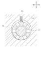
- FIG. 3 is a partial sectional view taken along line AA in FIG. 2.
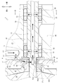
- turbocharger 1 including a lubricating oil supply mechanism according to an embodiment (first embodiment) of the present invention will be described with reference to FIGS. 1 and 2.
- the turbocharger 1 shown in FIG. 1 is for sending compressed air into a cylinder of an engine.
- the turbocharger 1 mainly includes a shaft 10, a compressor wheel 20, a turbine wheel 30, a bearing housing 40, a slide bearing 50, a thrust collar 60, a thrust bearing 70, a compressor housing 80 and a turbine housing 90.
- the shaft 10 connects a compressor wheel 20 and a turbine wheel 30 described later.
- the shaft 10 is disposed with its longitudinal direction (axial direction) directed in the front-rear direction.
- the compressor wheel 20 has a plurality of blades, and compresses air by being driven to rotate.
- the compressor wheel 20 is fixed to the rear end portion of the shaft 10.
- the turbine wheel 30 has a plurality of blades, and generates driving force by rotating by receiving exhaust from the engine.
- the turbine wheel 30 is formed integrally with the front end portion of the shaft 10.
- the bearing housing 40 shown in FIGS. 1 and 2 supports the shaft 10 so that it can rotate indirectly.
- a bearing portion 41 and a thrust bearing portion 42 are formed in the bearing housing 40.
- the bearing portion 41 is a portion that supports the shaft 10 so as to be indirectly rotatable.
- the bearing portion 41 has a circular cross section and is formed so as to penetrate the bearing housing 40 in the front-rear direction.
- the thrust bearing portion 42 is a portion that indirectly receives the axial load of the shaft 10.
- the thrust bearing portion 42 is formed by denting the rear side surface of the bearing housing 40 (around the portion where the bearing portion 41 is open).
- the sliding bearing 50 is an embodiment of a bearing according to the present invention, and is a substantially cylindrical bearing that supports the shaft 10 rotatably.
- the slide bearing 50 is disposed in the vicinity of the front end portion and the rear end portion of the bearing portion 41 of the bearing housing 40, respectively.
- the shaft 10 is inserted into the slide bearing 50.
- the thrust collar 60 transmits an axial load applied to the shaft 10 to a thrust bearing 70 described later.
- the thrust collar 60 includes a first collar 61 and a second collar 62 (see FIG. 2).
- the first collar 61 shown in FIG. 2 is formed so as to expand in diameter from the rear end portion of the cylindrical portion 61a to the outside of the cylindrical portion 61a. And a substantially cylindrical rear cylindrical portion 61c formed rearward from the rear side surface of the circular disc portion 61b.
- the first collar 61 is disposed immediately behind the bearing portion 41 of the bearing housing 40.
- the shaft 10 is inserted through the first collar 61.
- a seal plate 65 is fitted on the rear cylindrical portion 61 c of the first collar 61.
- the second collar 62 is a substantially disk-shaped member having an opening at the center.
- the second collar 62 is disposed immediately behind the bearing portion 41 of the bearing housing 40 and immediately in front of the first collar 61.
- a shaft is inserted through the second collar 62.
- an annular groove is formed between the disc portion 61b of the first collar 61 and the second collar 62. Become. Further, the thrust collar 60 is fixed so as not to rotate relative to the shaft 10.
- the thrust bearing 70 shown in FIGS. 1 and 2 receives a load in the axial direction of the shaft 10.
- the thrust bearing 70 is formed in a substantially flat plate shape.
- the thrust bearing 70 is formed with a through hole 71 that penetrates the thrust bearing 70 in the front-rear direction (see FIG. 2).
- the inner diameter of the through hole 71 is formed to be slightly larger than the outer diameter of the cylindrical portion 61 a of the thrust collar 60.
- the cylindrical portion 61a of the thrust collar 60 is inserted into the through hole 71 of the thrust bearing 70, and the thrust bearing 70 is sandwiched between the grooves of the thrust collar 60 (between the disc portion 61b and the second collar 62).
- the thrust bearing 70 is fixed to the thrust bearing portion 42 of the bearing housing 40 in this state.
- the shaft 10 and the thrust collar 60 can rotate integrally, whereas the thrust bearing 70 is fixed to the bearing housing 40 and does not rotate.
- a compressor housing 80 shown in FIG. 1 contains the compressor wheel 20.
- the compressor housing 80 is fixed to the rear end of the bearing housing 40.
- the compressor housing 80 forms a flow path for the air so that the air supplied to the engine passes through the compressor wheel 20.
- the turbine housing 90 contains the turbine wheel 30.
- the turbine housing 90 is fixed to the front end of the bearing housing 40.
- the turbine housing 90 forms a flow path of the exhaust so that the exhaust from the engine passes through the turbine wheel 30.
- the turbine wheel 30 rotates upon receiving high-temperature air (exhaust gas) after combustion in the cylinder of the engine.
- the rotation of the turbine wheel 30 is transmitted to the compressor wheel 20 through the shaft 10, and the compressor wheel 20 rotates. Then, the compressor wheel 20 rotates to compress the air, and the compressed air can be supplied to the engine cylinder.
- 1 and 2 are provided with a supply oil passage 43 and a discharge oil passage 44 through which lubricating oil flows.
- the supply oil passage 43 is an oil passage that guides lubricating oil supplied from the outside to the thrust bearing portion 42 of the bearing housing 40.
- One end (upper end) of the supply oil passage 43 communicates with the outer surface of the bearing housing 40.
- the other end (lower end) of the supply oil passage 43 communicates with the thrust bearing portion 42 of the bearing housing 40.
- the drain oil passage 44 is an oil passage through which lubricating oil after each part is lubricated is discharged to the outside.
- One end (lower end) of the discharge oil passage 44 is communicated with the outer surface of the bearing housing 40.
- the other end (upper end) of the discharge oil passage 44 is branched into two and communicates with the bearing portion 41 and the thrust bearing portion 42 of the bearing housing 40.
- the oil passage 72 is an oil passage that guides the lubricating oil to the through hole 71 of the thrust bearing 70.
- One end (upper end portion) of the oil passage 72 is in communication with a front surface of the thrust bearing 70 and a position facing the other end (lower end portion) of the supply oil passage 43 of the bearing housing 40.
- the other end (lower end) of the oil passage 72 communicates with the through hole 71 of the thrust bearing 70.
- an oil passage 61d through which lubricating oil flows is formed.
- the oil passage 61 d is an oil passage that guides the lubricating oil into the thrust collar 60.
- the oil passage 61d is formed so as to penetrate the cylindrical portion 61a of the thrust collar 60 in the diameter direction (a direction passing through the axis of the cylindrical portion 61a and perpendicular to the axis). As a result, the opposite position on the outer peripheral surface of the cylindrical portion 61a communicates with the inside of the cylindrical portion 61a.
- 2 to 4 are formed with an axial oil passage 11, a supply oil passage 12, and a radial oil passage 13 through which lubricating oil flows.
- the axial oil passage 11 is an oil passage formed along the axial direction (front-rear direction) of the shaft 10.
- the axial oil passage 11 is formed on the axis of the shaft 10.
- the axial oil passage 11 extends from a front end portion of the shaft 10 (turbine wheel 30) to a predetermined position on the rear end side (specifically, a portion inserted through the thrust collar 60).
- the front end side of the axial oil passage 11 is closed by a lid member (not shown).
- the supply oil passage 12 is formed so as to penetrate a portion inserted through the thrust collar 60 of the shaft 10 in the diameter direction. As a result, the central portion of the supply oil passage 12 communicates with the axial oil passage 11. Further, both end portions of the supply oil passage 12 are formed so as to face the oil passage 61d of the thrust collar 60, respectively. As a result, the supply oil passage 12 of the shaft 10 and the oil passage 61d of the thrust collar 60 are communicated.
- the radial oil passage 13 is formed so as to penetrate through a portion of the shaft 10 inserted through the slide bearing 50 (a portion facing the inner peripheral surface of the slide bearing 50) in the diameter direction. Accordingly, the central portion of the radial oil passage 13 is communicated with the axial oil passage 11, and both end portions of the radial oil passage 13 are opened on the outer peripheral surface of the shaft 10.
- the diameter (cross-sectional area) of the radial oil passage 13 is formed to be smaller than the diameter (cross-sectional area) of the axial oil passage 11 (see FIG. 4).
- an oil passage 51 through which lubricating oil flows is formed.
- the oil passage 51 is an oil passage that guides the lubricating oil on the inner peripheral side of the slide bearing 50 to the outer peripheral side.
- a plurality (six in this embodiment) of the oil passages 51 are formed radially in the middle of the sliding bearing 50 so as to communicate the inner peripheral surface and the outer peripheral surface of the sliding bearing 50.
- a part of the lubricating oil supplied to the through-hole 71 of the thrust bearing 70 is supplied to the lubricating portion (the portion to be lubricated) of the thrust bearing 70 and lubricates the portion.
- the lubricating oil is a sliding portion between the thrust bearing 70 and the thrust collar 60 (the sliding surface between the thrust bearing 70 and the disc portion 61b of the first collar 61, and the thrust bearing 70 and the second collar 62). Lubricate the sliding surface.
- the lubricating oil that has lubricated the sliding portion is discharged to the outside through a discharge oil passage 44 communicated with the thrust bearing portion 42 (see FIG. 1).
- the remainder of the lubricating oil supplied to the through hole 71 of the thrust bearing 70 (lubricating oil other than the lubricating oil that lubricates the lubrication portion of the thrust bearing 70) is the thrust collar 60. And is guided to the axial oil passage 11 of the shaft 10 through the oil passage 61 d of the thrust collar 60 and the supply oil passage 12 of the shaft 10.
- the turbine wheel 30 see FIG. 1
- the thrust collar 60 and the shaft 10 rotate integrally, but the circumference of the cylindrical portion 61a of the thrust collar 60 (the annular shape of the thrust collar 60).
- Is filled with lubricating oil so that the lubricating oil can be supplied into the oil passage 61d regardless of the direction of the oil passage 61d of the thrust collar 60.
- the lubricating oil supplied to the axial oil passage 11 of the shaft 10 is supplied to the slide bearing 50 via the axial oil passage 11 and the radial oil passage 13. . More specifically, the lubricating oil is supplied to a sliding portion between the shaft 10 and the sliding bearing 50 (a portion where the outer peripheral surface of the shaft 10 and the inner peripheral surface of the sliding bearing 50 face each other), and lubricates the portion. To do.
- the lubricating oil supplied to the sliding portion between the shaft 10 and the slide bearing 50 is supplied to the outer peripheral side through the oil passage 51 of the slide bearing 50. More specifically, the lubricating oil is supplied to a sliding portion between the sliding bearing 50 and the bearing portion 41 (a portion where the outer peripheral surface of the sliding bearing 50 and the inner peripheral surface of the bearing portion 41 face each other). Lubricate.
- the lubricating oil that has lubricated the slide bearing 50 is discharged to the outside through the bearing portion 41 and the discharge oil passage 44 communicated with the bearing portion 41 (see FIGS. 1 and 2).
- the lubricating oil supply mechanism of the turbocharger 1 is a slide that rotatably supports the shaft 10 in a state where it is fitted to the outside of the shaft 10 that connects the turbine wheel 30 and the compressor wheel 20.
- a lubricating oil supply mechanism of the turbocharger 1 for supplying lubricating oil to a bearing 50 (bearing), which is formed in the shaft 10 and through an oil passage that is opened in an outer peripheral surface facing the sliding bearing 50.
- lubricating oil is supplied to the sliding portion between the shaft 10 and the plain bearing 50.
- the lubricating oil can be supplied to the sliding bearing 50 for a longer time (that is, for a while after the engine is stopped). Further, by supplying the lubricating oil from the inside of the sliding bearing 50 (on the shaft 10 side), the centrifugal oil of the rotating shaft 10 and the sliding bearing 50 is used to reliably supply the lubricating oil to the outside of the shaft 10 and the sliding bearing 50. Can supply up to.
- the oil passage includes a radial oil passage 13 penetrating the shaft 10 in the diameter direction, and is opened to an outer peripheral surface facing the slide bearing 50 by the radial oil passage 13.
- the lubricating oil is supplied in the opposite direction via the radial oil passage 13, so that it is possible to more effectively suppress the biased pressure applied to the slide bearing 50.
- the oil passage includes an axial oil passage 11 that is formed along the axial direction of the shaft 10 so as to communicate with the radial oil passage 13 and supplies lubricating oil to the radial oil passage 13.
- the diameter of the directional oil passage 11 is formed to be larger than the diameter of the radial oil passage 13.
- the lubricating oil is supplied to a thrust bearing 70 that receives a load in the axial direction of the shaft 10. A part of the lubricating oil lubricates the lubrication portion of the thrust bearing 70, and Other lubricating oil is supplied to the oil passage of the shaft 10.
- the lubricating oil supplied from the outside is not supplied separately to the sliding bearing 50 and the thrust bearing 70 by branching the oil passage, but after being supplied to the thrust bearing 70 as in the present embodiment, the sliding bearing is provided.
- the sliding bearing is provided.
- the diameter of the radial oil passage 13 on the upstream side (rear side in the present embodiment) of the lubricating oil is reduced.
- the lubricating oil supplied to the plurality of slide bearings 50 in consideration of the pressure loss of the lubricating oil by increasing the diameter of the radial oil passage 13 on the downstream side (the front side in the present embodiment) of the lubricating oil. It can also be set as the structure which aims at equalization of the amount of oil.
- the diameter of the oil passage 13 on the front side is further increased, and a large amount of lubricating oil is supplied to the front slide bearing 50, so that the slip on the turbine wheel 30 side, which is likely to be hot. It can also be set as the structure which aims at the improvement of the cooling effect of the bearing 50.
- the shape of the oil passage of the lubricating oil supply mechanism according to the present invention is not limited to that illustrated in the present embodiment.
- the supply oil passage 43 and the discharge oil passage 44 formed in the bearing housing 40, the oil passage 72 formed in the thrust bearing 70, the oil passage 61d formed in the thrust collar 60, and the like are formed in an arbitrary shape. Is possible.
- two sliding bearings 50 (bearings) are provided, but the present invention is not limited to this. That is, it is possible to adopt a configuration in which one slide bearing that is long in the front-rear direction is provided, or a configuration in which three or more are provided.
- the radial oil passage 13 penetrating the shaft 10 in the diametrical direction is illustrated as being formed for one slide bearing 50 (see FIG. 4), but the present invention is not limited to this. It is not limited to. In other words, it is possible to form a plurality of radial oil passages 13 for one slide bearing 50.
- oil passages 51 are formed in the slide bearing 50, but the present invention is not limited to this. That is, the oil passages 51 may be provided at equal intervals in the circumferential direction of the slide bearing 50, and the number thereof is not limited.
- the configuration of the thrust collar 60 is not limited to this embodiment.
- a configuration in which the cylindrical portion 61a of the first collar 61 is inserted into the inner diameter portion of the second collar 62, a configuration in which the first collar 61 and the second collar 62 are integrally formed, or the like may be used.
- the configuration of the thrust bearing 70 is not limited to this embodiment.
- a configuration in which the thrust bearing 70 is divided in the radial direction, a configuration in which a plurality of oil passages 72 of the thrust bearing 70 are provided in the thrust bearing 70, or the like may be used.
- An oil passage 52 is formed in the slide bearing 50 according to the second embodiment.
- the oil passage 52 is an oil passage that guides the lubricating oil on the inner peripheral side of the slide bearing 50 to the outer peripheral side.
- a plurality (six in this embodiment) of oil passages 52 are formed in the midway part before and after the slide bearing 50 so as to communicate the inner peripheral surface and the outer peripheral surface of the slide bearing 50.
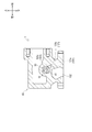
- the oil passage 52 is formed in a straight line inclined by a predetermined angle with respect to the radial direction of the slide bearing 50. Specifically, when the shaft 10 rotates counterclockwise in a front view (FIG. 6), the oil passage 52 is formed so as to incline clockwise from the inside toward the outside.
- the lubricating oil from the axial oil passage 11 of the shaft 10 passes through the radial oil passage 13 through the sliding portion (the outer periphery of the shaft 10) between the shaft 10 and the slide bearing 50. To the portion where the surface and the inner peripheral surface of the slide bearing 50 face each other), and lubricates the portion.
- the lubricating oil supplied to the sliding portion between the shaft 10 and the sliding bearing 50 is supplied to the outer peripheral side through the oil passage 52 of the sliding bearing 50.
- the oil passage 52 is formed so as to be inclined at a predetermined angle with respect to the radial direction of the slide bearing 50 as described above, the lubricating oil that has circulated through the oil passage 52 passes through the outer end of the oil passage 52. It is discharged (spouted) from the portion in the clockwise direction when viewed from the front.
- the sliding bearing 50 is urged to rotate in the counterclockwise direction when viewed from the front by the reaction of the lubricant oil jetting through the oil passage 52 in the clockwise direction when viewed from the front.
- the relative speed (difference in rotational speed) between the sliding bearing 50 and the shaft 10 decreases. Accordingly, it is possible to reduce the friction loss between the sliding bearing 50 and the shaft 10 and to improve the response of the sliding bearing 50 to the shaft 10.
- the oil passage 52 is formed so as to be inclined in the opposite direction to that of the second embodiment (see FIG. 6), similarly to the second embodiment.
- the sliding bearing 50 can be prompted to rotate in the same direction as the shaft 10. That is, in this case, the oil passage 52 may be formed so as to be inclined counterclockwise from the inside toward the outside.
- the third embodiment differs from the first embodiment in the configuration of an oil passage for supplying lubricating oil to the slide bearing 50. That is, in the first embodiment, the lubricating oil supplied from the external hydraulic pump is supplied to the slide bearing 50 through the bearing housing 40, the thrust bearing 70, the thrust collar 60, and the shaft 10. However, in the third embodiment, the oil is supplied to the slide bearing 50 through the supply oil passage 101 formed in the bearing housing 40. This will be specifically described below.
- turbocharger 1 of a different type from the turbocharger 1 according to the first embodiment will be described as an example.
- symbol is attached
- the supply oil passage 101 is an oil passage that guides the lubricating oil supplied from the outside to the bearing portion 41 (slide bearing 50).
- the supply oil passage 101 mainly includes a vertical oil passage 101a, a branch oil passage 101b, a rear oil passage 101c, and a front oil passage 101d.
- the vertical oil path 101a is an oil path formed in the bearing housing 40 in the vertical direction.
- One end (lower end) of the upper and lower oil passages 101a communicates with the outside of the bearing housing 40 (the hydraulic pump).
- the other end (upper end) of the upper and lower oil passages 101 a extends to the right of the bearing portion 41.
- the branch oil passage 101b is an oil passage formed in the bearing housing 40 in the front-rear direction.
- the branch oil passage 101 b is formed on the right side of the bearing portion 41.
- One end (front end) of the branch oil passage 101b extends to the same position in the front-rear direction as the slide bearing 50 disposed on the front side.
- the other end (rear end) of the branch oil passage 101b extends to the same position in the front-rear direction as the slide bearing 50 disposed on the rear side.
- the midway portion before and after the branch oil passage 101b communicates with the upper end of the upper and lower oil passages 101a.
- a rear oil passage 101c shown in FIG. 7 to FIG. 9 is a straight oil passage communicating the branch oil passage 101b and the bearing portion 41.
- the diameter of the rear oil passage 101 c is formed so as to be smaller than the diameter of the bearing portion 41.
- One end (lower right end) of the rear oil passage 101c communicates with the rear end portion of the branch oil passage 101b.
- the other end (left upper end) of the rear oil passage 101c is formed so as to extend to the upper left, and communicates with the bearing portion 41 (a portion facing the slide bearing 50 disposed on the rear side).
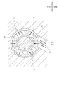
- the rear oil passage 101c is formed such that the axis S1 of the rear oil passage 101c does not intersect the axis S2 of the bearing portion 41.
- the rear oil passage 101c is formed such that the axis S1 of the rear oil passage 101c passes above the axis S2 of the bearing portion 41.
- the front oil passage 101d shown in FIG. 7 is a linear oil passage that communicates the branch oil passage 101b and the bearing portion 41.
- One end (lower right end) of the front oil passage 101d communicates with the front end of the branch oil passage 101b.
- the other end (upper left end) of the front oil passage 101d is formed so as to extend to the upper left and communicates with the bearing portion 41 (the portion facing the plain bearing 50 disposed on the front side).
- the shape of the front oil passage 101d is substantially the same as that of the rear oil passage 101c when viewed from the front, and the description thereof is omitted.
- the 7 and 8 is an oil passage for discharging the lubricating oil after lubricating each part to the outside.
- One end (lower end) of the discharge oil passage 102 is communicated with the outside of the bearing housing 40.
- the other end (upper end portion) of the drain oil passage 44 is branched into three and communicates with the front end portion of the bearing portion 41, the front and rear intermediate portions of the bearing portion 41, and the thrust bearing portion 42.
- the lubricating oil supply mechanism configured as described above, when lubricating oil is supplied from the hydraulic pump to one end of the upper and lower oil passages 101a, the lubricating oil is guided to the branch oil passage 101b via the upper and lower oil passages 101a. Is done.
- the lubricating oil branches forward and backward in the branch oil passage 101b and is supplied to the bearing portion 41 via the rear oil passage 101c and the front oil passage 101d, respectively.
- the lubricating oil supplied to the bearing portion 41 lubricates the sliding portion between the sliding bearing 50 and the bearing portion 41 (the portion where the outer peripheral surface of the sliding bearing 50 and the inner peripheral surface of the bearing portion 41 face each other). Further, the lubricating oil supplied to the bearing portion 41 is supplied to the inner peripheral side of the sliding bearing 50 through the oil passage 51 of the sliding bearing 50 (see FIG. 9). The lubricating oil lubricates a sliding portion between the shaft 10 and the slide bearing 50 (a portion where the outer peripheral surface of the shaft 10 and the inner peripheral surface of the slide bearing 50 face each other).
- the lubricating oil that has lubricated the slide bearing 50 is discharged to the outside through the bearing portion 41 and the discharge oil passage 102 communicated with the bearing portion 41.
- the lubricating oil flowing into the bearing portion 41 via the front oil passage 101d can be similarly urged to rotate the plain bearing 50 disposed on the front side in the counterclockwise direction when viewed from the front.
- the lubricating oil flowing into the bearing portion 41 via the rear oil passage 101c rotates clockwise in the front view.
- the sliding bearing 50 is urged to rotate in the same direction as the shaft 10 as in the third embodiment. it can. That is, in this case, the rear oil passage 101c is formed such that the axis S1 of the rear oil passage 101c passes below the axis S2 of the bearing portion 41, or the rear oil passage 101c is formed on the left side of the bearing portion 41. It ’s fine.
- the present invention is applied to a lubricating oil supply mechanism of a turbocharger for supplying lubricating oil to a bearing that rotatably supports the shaft in a state of being fitted on the outer side of the shaft connecting the turbine wheel and the compressor wheel. Can do.
Landscapes
- Engineering & Computer Science (AREA)
- General Engineering & Computer Science (AREA)
- Mechanical Engineering (AREA)
- Chemical & Material Sciences (AREA)
- Oil, Petroleum & Natural Gas (AREA)
- Combustion & Propulsion (AREA)
- Supercharger (AREA)
Abstract
軸受及びシャフトに偏った圧力が加わるのを抑制し、当該軸受のシャフトに対する応答を向上させることが可能なターボチャージャの潤滑油供給機構を提供する。 タービンホイールとコンプレッサホイール20とを連結するシャフト10の外側にはめられた状態で当該シャフト10を回転可能に支持するすべり軸受50に潤滑油を供給するためのターボチャージャ1の潤滑油供給機構であって、シャフト10内に形成されると共に、すべり軸受50と対向する外周面に開口された油路を介して、当該シャフト10と当該すべり軸受50との摺動部に潤滑油を供給する。
Description
本発明は、タービンホイールとコンプレッサホイールとを連結するシャフトの外側にはめられた状態で当該シャフトを回転可能に支持する軸受に潤滑油を供給するためのターボチャージャの潤滑油供給機構の技術に関する。
従来、タービンホイールとコンプレッサホイールとを連結するシャフトの外側にはめられた状態で当該シャフトを回転可能に支持する軸受に潤滑油を供給するためのターボチャージャの潤滑油供給機構の技術は公知となっている。例えば、特許文献1に記載の如くである。
特許文献1には、タービンホイール(タービンロータ)とコンプレッサホイール(コンプレッサインペラ)とを連結するシャフトを有するターボチャージャが開示されている。当該シャフトは、軸受(ラジアルベアリング)を介してベアリングハウジング(ベアリングハウジング本体及びブッシュ)に回転可能に支持されている。このベアリングハウジングには潤滑油を案内する油路が形成され、当該油路を介して軸受に潤滑油が供給される。
しかしながら、特許文献1に記載の如きターボチャージャの潤滑油供給機構においては、以下で述べるような問題点があった。
上記潤滑油供給機構においては、図5に示すように、ベアリングハウジング940に形成された油路940aを介して、軸受950及びシャフト910の外周部に潤滑油が供給される(図5中の矢印参照)。当該供給される潤滑油によって、軸受950及びシャフト910は一方向(図5においては、紙面下方)に偏った圧力を受ける。このため、本来ならばシャフト910の回転に追従するようにして速やかに回転するはずの軸受950が潤滑油による抵抗を受けて回転し難くなり、当該シャフト910に対する応答(レスポンス)が悪化する。これによって、当該軸受950とベアリングハウジング940との間における油膜の形成が遅れるなど、不利な状態が発生する。
本発明は以上の如き状況に鑑みてなされたものであり、その解決しようとする課題は、軸受及びシャフトに偏った圧力が加わるのを抑制し、当該軸受のシャフトに対する応答を向上させることが可能なターボチャージャの潤滑油供給機構を提供することである。
本発明の解決しようとする課題は以上の如くであり、次にこの課題を解決するための手段を説明する。
即ち、本発明のターボチャージャの潤滑油供給機構は、タービンホイールとコンプレッサホイールとを連結するシャフトの外側にはめられた状態で当該シャフトを回転可能に支持する軸受に潤滑油を供給するためのターボチャージャの潤滑油供給機構であって、前記シャフト内に形成されると共に、前記軸受と対向する外周面に開口された油路を介して、当該シャフトと当該軸受との摺動部に潤滑油を供給するものである。
本発明のターボチャージャの潤滑油供給機構は、前記油路は、前記シャフトを直径方向に貫通する径方向油路を含み、当該径方向油路によって前記軸受と対向する外周面に開口されるものである。
本発明のターボチャージャの潤滑油供給機構は、前記油路は、前記径方向油路と連通するように前記シャフトの軸線方向に沿って形成され、当該径方向油路に潤滑油を供給する軸方向油路を含み、前記径方向油路の径は、前記軸方向油路の径よりも小さくなるように形成されるものである。
本発明のターボチャージャの潤滑油供給機構は、潤滑油は、前記シャフトの軸線方向の荷重を受けるスラスト軸受に供給され、その一部の潤滑油が前記スラスト軸受の潤滑部を潤滑すると共に、その他の潤滑油が前記シャフトの油路へと供給されるものである。
本発明の効果として、以下に示すような効果を奏する。
本発明のターボチャージャの潤滑油供給機構においては、シャフトを介して軸受の内側(シャフト側)から潤滑油を供給することで、当該軸受及びシャフトに偏った圧力が加わるのを抑制し、ひいては当該軸受のシャフトに対する応答を向上させることができる。
また、エンジンが停止した直後においても、シャフトが慣性によって回転していれば当該シャフトの遠心力によって軸受に潤滑油を供給することができる。これによって、より長い時間軸受に潤滑油を供給することができる。
また、エンジンが停止した直後においても、シャフトが慣性によって回転していれば当該シャフトの遠心力によって軸受に潤滑油を供給することができる。これによって、より長い時間軸受に潤滑油を供給することができる。
本発明のターボチャージャの潤滑油供給機構においては、径方向油路を介して相反する方向に潤滑油が供給されるため、軸受に偏った圧力が加わるのをより効果的に抑制することができる。
本発明のターボチャージャの潤滑油供給機構においては、軸受に潤滑油を供給する径方向油路の径を絞ることで、潤滑油の供給過多を防止することができる。また、エンジンが停止した後(すなわち、外部からの潤滑油の供給が停止した後)にシャフトが慣性によって回転している場合、当該シャフトの遠心力によって軸受に供給される潤滑油の量を制限することができ、より長い時間軸受に潤滑油を供給することができる。
本発明のターボチャージャの潤滑油供給機構においては、特に潤滑油による潤滑を要するスラスト軸受を優先して潤滑することができる。
以下では、図中に示した矢印に従って、上下方向、前後方向及び左右方向を定義する。
まず、図1及び図2を用いて、本発明の一実施形態(第一実施形態)に係る潤滑油供給機構を具備するターボチャージャ1の構成について説明する。
図1に示すターボチャージャ1は、エンジンのシリンダに圧縮空気を送り込むためのものである。ターボチャージャ1は、主としてシャフト10、コンプレッサホイール20、タービンホイール30、ベアリングハウジング40、すべり軸受50、スラストカラー60、スラスト軸受70、コンプレッサハウジング80及びタービンハウジング90を具備する。
シャフト10は、後述するコンプレッサホイール20とタービンホイール30とを連結するものである。シャフト10は、その長手方向(軸線方向)を前後方向へ向けて配置される。
コンプレッサホイール20は、複数の羽根を有し、回転駆動されることによって空気を圧縮するものである。コンプレッサホイール20は、シャフト10の後端部に固定される。
タービンホイール30は、複数の羽根を有し、前記エンジンからの排気を受けて回転することで駆動力を発生させるものである。タービンホイール30は、シャフト10の前端部に一体的に形成される。
図1及び図2に示すベアリングハウジング40は、シャフト10を間接的に回転可能に支持するものである。ベアリングハウジング40には、軸受部41及びスラスト軸受部42が形成される。
軸受部41は、シャフト10を間接的に回転可能に支持する部分である。軸受部41は円形断面を有し、ベアリングハウジング40を前後方向に貫通するように形成される。
スラスト軸受部42は、シャフト10の軸線方向の荷重を間接的に受ける部分である。スラスト軸受部42は、ベアリングハウジング40の後側面(軸受部41が開口している部分の周辺)を凹ませることによって形成される。
すべり軸受50は、本発明に係る軸受の実施の一形態であり、シャフト10を回転可能に支持する略円筒状の軸受である。すべり軸受50は、ベアリングハウジング40の軸受部41の前端部近傍及び後端部近傍にそれぞれ配置される。当該すべり軸受50にはシャフト10が挿通される。
スラストカラー60は、シャフト10に加わる軸線方向の荷重を後述するスラスト軸受70に伝えるものである。スラストカラー60は、第一カラー61及び第二カラー62を具備する(図2参照)。
図2に示す第一カラー61は、前後方向に向けて配置された略円筒状の円筒部61aと、当該円筒部61aの後端部から当該円筒部61aの外側へと拡径するように形成された略円板状の円板部61bと、当該円板部61bの後側面からさらに後方に向けて形成された略円筒状の後円筒部61cと、を具備する。第一カラー61はベアリングハウジング40の軸受部41のすぐ後方に配置される。第一カラー61にはシャフト10が挿通される。第一カラー61の後円筒部61cには、シールプレート65が外嵌される。
第二カラー62は、中央が開口された略円板状の部材である。第二カラー62はベアリングハウジング40の軸受部41のすぐ後方かつ第一カラー61のすぐ前方に配置される。第二カラー62にはシャフトが挿通される。
このように構成されたスラストカラー60(第一カラー61と第二カラー62)において、第一カラー61の円板部61bと第二カラー62との間に円環状の溝が形成されることになる。また、当該スラストカラー60は、シャフト10に対して相対回転不能となるように固定される。
図1及び図2に示すスラスト軸受70は、シャフト10の軸線方向の荷重を受けるものである。スラスト軸受70は、略平板状に形成される。スラスト軸受70には、当該スラスト軸受70を前後方向に貫通する貫通孔71が形成される(図2参照)。当該貫通孔71の内径は、スラストカラー60の円筒部61aの外径よりも若干大きくなるように形成される。スラスト軸受70の貫通孔71には、スラストカラー60の円筒部61aが挿通され、当該スラスト軸受70は、スラストカラー60の溝(円板部61bと第二カラー62との間)に挟まれる。当該スラスト軸受70は、この状態でベアリングハウジング40のスラスト軸受部42に固定される。これによって、シャフト10とスラストカラー60が一体的に回転可能であるのに対し、スラスト軸受70はベアリングハウジング40に固定されて回転しない。
図1に示すコンプレッサハウジング80は、コンプレッサホイール20を内包するものである。コンプレッサハウジング80は、ベアリングハウジング40の後端に固定される。当該コンプレッサハウジング80によって、前記エンジンへと供給される空気がコンプレッサホイール20を通過するように、当該空気の流路が形成される。
タービンハウジング90は、タービンホイール30を内包するものである。タービンハウジング90は、ベアリングハウジング40の前端に固定される。当該タービンハウジング90によって、前記エンジンからの排気がタービンホイール30を通過するように、当該排気の流路が形成される。
このように構成されたターボチャージャ1において、エンジンのシリンダ内で燃焼した後の高温の空気(排気)を受けてタービンホイール30が回転する。当該タービンホイール30の回転は、シャフト10を介してコンプレッサホイール20に伝達され、当該コンプレッサホイール20が回転する。そして、当該コンプレッサホイール20が回転することにより空気を圧縮し、当該圧縮された空気を前記エンジンのシリンダへと供給することができる。
次に、図1から図4までを用いて、すべり軸受50に潤滑油を供給するための機構(潤滑油供給機構)について説明する。
図1及び図2に示すベアリングハウジング40には、潤滑油が流通する供給油路43及び排出油路44が形成される。
供給油路43は、外部から供給される潤滑油をベアリングハウジング40のスラスト軸受部42まで案内する油路である。供給油路43の一端(上側端部)は、ベアリングハウジング40の外側面に連通される。供給油路43の他端(下側端部)は、ベアリングハウジング40のスラスト軸受部42に連通される。
排出油路44は、各部を潤滑した後の潤滑油を外部へと排出する油路である。排出油路44の一端(下側端部)は、ベアリングハウジング40の外側面に連通される。排出油路44の他端(上側端部)は2つに分岐されて、ベアリングハウジング40の軸受部41及びスラスト軸受部42に連通される。
図2及び図3に示すスラスト軸受70には、潤滑油が流通する油路72が形成される。
油路72は、潤滑油をスラスト軸受70の貫通孔71へと案内する油路である。油路72の一端(上側端部)は、スラスト軸受70の前面であり、かつベアリングハウジング40の供給油路43の他端(下側端部)と対向する位置に連通される。油路72の他端(下側端部)は、スラスト軸受70の貫通孔71と連通される。
スラストカラー60には、潤滑油が流通する油路61dが形成される。
油路61dは、潤滑油をスラストカラー60の内部へと案内する油路である。油路61dは、スラストカラー60の円筒部61aを直径方向(円筒部61aの軸線を通り、当該軸線と直交する方向)に貫通するように形成される。これによって、円筒部61aの外周面上の相反する位置と、当該円筒部61aの内部が連通される。
図2から図4までに示すシャフト10には、潤滑油が流通する軸方向油路11、供給油路12及び径方向油路13が形成される。
軸方向油路11は、シャフト10の軸線方向(前後方向)に沿って形成される油路である。軸方向油路11は、シャフト10の軸線上に形成される。軸方向油路11は、シャフト10(タービンホイール30)の前端部から後端側の所定位置(具体的には、スラストカラー60に挿通されている部分)まで延設される。軸方向油路11の前端側は、図示しない蓋部材によって閉塞される。
図2及び図3に示す供給油路12は、潤滑油を軸方向油路11へと案内する油路である。供給油路12は、シャフト10のスラストカラー60に挿通された部分を直径方向に貫通するように形成される。これによって、当該供給油路12の中央部は軸方向油路11と連通される。また、供給油路12の両端部は、それぞれスラストカラー60の油路61dと対向するように形成される。これによって、シャフト10の供給油路12とスラストカラー60の油路61dとが連通される。
図2及び図4に示す径方向油路13は、軸方向油路11から供給される潤滑油をシャフト10の外部へと案内する油路である。径方向油路13は、シャフト10のすべり軸受50に挿通された部分(すべり軸受50の内周面と対向する部分)をそれぞれ直径方向に貫通するように形成される。これによって、当該径方向油路13の中央部は軸方向油路11と連通されると共に、当該径方向油路13の両端部はそれぞれシャフト10の外周面に開口される。径方向油路13の径(断面積)は、軸方向油路11の径(断面積)よりも小さくなるように形成される(図4参照)。
すべり軸受50には、潤滑油が流通する油路51が形成される。
油路51は、すべり軸受50の内周側の潤滑油を外周側へと案内する油路である。油路51は、すべり軸受50の前後中途部において、当該すべり軸受50の内周面と外周面とを連通するように放射状に複数(本実施形態においては、6つ)形成される。
次に、図1から図4までを用いて、上述の如く構成された潤滑油供給機構によってすべり軸受50に潤滑油が供給されるまでの様子について説明する。
図2に示すように、外部の油圧ポンプ(不図示)からベアリングハウジング40の供給油路43の一端へと潤滑油が供給されると、当該潤滑油は供給油路43を介してスラスト軸受部42へと案内される。当該潤滑油は、供給油路43と対向して配置されたスラスト軸受70の油路72へと流入する。当該潤滑油は、油路72を介してスラスト軸受70の貫通孔71へと案内される。
スラスト軸受70の貫通孔71へと供給された潤滑油の一部は、スラスト軸受70の潤滑部(潤滑すべき部分)へと供給され、当該部分を潤滑する。具体的には、潤滑油は、スラスト軸受70とスラストカラー60との摺動部(スラスト軸受70と第一カラー61の円板部61bとの摺動面、及びスラスト軸受70と第二カラー62との摺動面)を潤滑する。当該摺動部を潤滑した潤滑油は、スラスト軸受部42に連通された排出油路44を介して外部へと排出される(図1参照)。
また、図2及び図3に示すように、スラスト軸受70の貫通孔71へと供給された潤滑油の残り(スラスト軸受70の潤滑部を潤滑する潤滑油以外の潤滑油)は、スラストカラー60の円環状の溝を満たすと共に、スラストカラー60の油路61d及びシャフト10の供給油路12を介して当該シャフト10の軸方向油路11へと案内される。この際、タービンホイール30(図1参照)が前記エンジンの排気を受けるとスラストカラー60及びシャフト10は一体的に回転するが、当該スラストカラー60の円筒部61aの周囲(スラストカラー60の円環状の溝)は潤滑油で満たされているため、当該スラストカラー60の油路61dがどの方向を向いていても当該油路61d内へと潤滑油を供給することができる。
図2及び図4に示すように、シャフト10の軸方向油路11へと供給された潤滑油は、当該軸方向油路11及び径方向油路13を介してすべり軸受50へと供給される。より詳細には、当該潤滑油は、シャフト10とすべり軸受50との摺動部(シャフト10の外周面とすべり軸受50の内周面とが対向する部分)へと供給され、当該部分を潤滑する。
また、シャフト10とすべり軸受50との摺動部へと供給された潤滑油は、当該すべり軸受50の油路51を介して外周側へと供給される。より詳細には、当該潤滑油はすべり軸受50と軸受部41との摺動部(すべり軸受50の外周面と軸受部41の内周面とが対向する部分)へと供給され、当該部分を潤滑する。
すべり軸受50を潤滑した潤滑油は、軸受部41及び当該軸受部41に連通された排出油路44を介して外部へと排出される(図1及び図2参照)。
以上の如く、本実施形態に係るターボチャージャ1の潤滑油供給機構は、タービンホイール30とコンプレッサホイール20とを連結するシャフト10の外側にはめられた状態で当該シャフト10を回転可能に支持するすべり軸受50(軸受)に潤滑油を供給するためのターボチャージャ1の潤滑油供給機構であって、シャフト10内に形成されると共に、すべり軸受50と対向する外周面に開口された油路を介して、当該シャフト10と当該すべり軸受50との摺動部に潤滑油を供給するものである。
このように構成することにより、シャフト10を介してすべり軸受50の内側(シャフト10側)から潤滑油を供給することで、当該すべり軸受50及びシャフト10に偏った圧力が加わるのを抑制することができる。これによって、シャフト10が回転した際の、当該シャフト10とすべり軸受50との間、並びにすべり軸受50と軸受部41との間における、油膜の形成を阻害し難くすることができ、ひいてはすべり軸受50のシャフト10に対する応答を向上させることができる。
また、前記エンジンが停止した直後(デッドソーク時など)においても、シャフト10が慣性によって回転していれば当該シャフト10の遠心力によって、内側からすべり軸受50に潤滑油を供給することができる。これによって、より長い時間(すなわち、前記エンジンが停止した後しばらくの間)すべり軸受50に潤滑油を供給することができる。
また、すべり軸受50の内側(シャフト10側)から潤滑油を供給することで、回転するシャフト10及びすべり軸受50の遠心力を利用して、潤滑油を確実にシャフト10及びすべり軸受50の外側まで供給することができる。
また、前記エンジンが停止した直後(デッドソーク時など)においても、シャフト10が慣性によって回転していれば当該シャフト10の遠心力によって、内側からすべり軸受50に潤滑油を供給することができる。これによって、より長い時間(すなわち、前記エンジンが停止した後しばらくの間)すべり軸受50に潤滑油を供給することができる。
また、すべり軸受50の内側(シャフト10側)から潤滑油を供給することで、回転するシャフト10及びすべり軸受50の遠心力を利用して、潤滑油を確実にシャフト10及びすべり軸受50の外側まで供給することができる。
また、前記油路は、シャフト10を直径方向に貫通する径方向油路13を含み、当該径方向油路13によってすべり軸受50と対向する外周面に開口されるものである。
このように構成することにより、径方向油路13を介して相反する方向に潤滑油が供給されるため、すべり軸受50に偏った圧力が加わるのをより効果的に抑制することができる。
また、前記油路は、径方向油路13と連通するようにシャフト10の軸線方向に沿って形成され、当該径方向油路13に潤滑油を供給する軸方向油路11を含み、当該軸方向油路11の径は、前記径方向油路13の径よりも大きくなるように形成されるものである。
このように構成することにより、すべり軸受50に潤滑油を供給する径方向油路13の径を絞ることで、潤滑油の供給過多を防止することができる。また、前記エンジンが停止した後(すなわち、外部からの潤滑油の供給が停止した後)にシャフト10が慣性によって回転している場合、当該シャフト10の遠心力によってすべり軸受50に供給される潤滑油の量を制限することができ、より長い時間すべり軸受50に潤滑油を供給することができる。
また、潤滑油は、シャフト10の軸線方向の荷重を受けるスラスト軸受70に供給され、
その一部の潤滑油がスラスト軸受70の潤滑部を潤滑すると共に、
その他の潤滑油がシャフト10の油路へと供給されるものである。
その一部の潤滑油がスラスト軸受70の潤滑部を潤滑すると共に、
その他の潤滑油がシャフト10の油路へと供給されるものである。
このように構成することにより、特に潤滑油による潤滑を要する(焼き付き等の発生し易い)スラスト軸受70を優先して潤滑することができる。
また、外部から供給される潤滑油を、油路を分岐させてすべり軸受50とスラスト軸受70のそれぞれに別々に供給するのではなく、本実施形態の如くスラスト軸受70に供給した後ですべり軸受50に供給する構成とすることで、各部における潤滑油の漏れを削減し、潤滑油全体の油量の削減を図ることができる。これによって、ターボチャージャ1に潤滑油を供給するための油圧ポンプの負担の軽減及び当該油圧ポンプの小型化を図ることができる。
また、本実施形態の如く、複数(2つ)のすべり軸受50に潤滑油を供給する場合、潤滑油の上流側(本実施形態においては、後側)の径方向油路13の径を小さく、潤滑油の下流側(本実施形態においては、前側)の径方向油路13の径を大きく形成することで、潤滑油の圧力損失を考慮し、複数のすべり軸受50に供給される潤滑油の油量の均等化を図る構成とすることもできる。
また、前側(タービンホイール30側)の径方向油路13の径をさらに大きく形成し、当該前側のすべり軸受50により多くの潤滑油を供給することで、高温になりやすいタービンホイール30側のすべり軸受50の冷却効果の向上を図る構成とすることもできる。
なお、本発明に係る潤滑油供給機構の油路の形状は、本実施形態において例示したものに限るものではない。例えば、ベアリングハウジング40に形成された供給油路43及び排出油路44、スラスト軸受70に形成された油路72、スラストカラー60に形成された油路61d等は、任意の形状に形成することが可能である。
また、本実施形態においては、すべり軸受50(軸受)は2つ設けるものとしたが、本発明はこれに限るものではない。すなわち、前後方向に長いすべり軸受を1つ設ける構成や、3つ以上設ける構成とすることも可能である。
また、本実施形態においては、シャフト10を直径方向に貫通する径方向油路13は、1つのすべり軸受50に対して1本形成するものとして例示(図4参照)したが、本発明はこれに限るものではない。すなわち、径方向油路13を1つのすべり軸受50に対して複数形成することも可能である。
また、本実施形態においては、すべり軸受50に油路51を6つ形成するものとしたが、本発明はこれに限るものではない。すなわち、油路51はすべり軸受50円周方向に等間隔に設けられていれば良く、その数を限定するものではない。
また、スラストカラー60の構成は本実施形態に限るものではない。例えば、第一カラー61の円筒部61aが第二カラー62の内径部に挿入される構成や、第一カラー61と第二カラー62を一体として形成する構成等であっても良い。
また、スラスト軸受70の構成は本実施形態に限るものではない。例えば、スラスト軸受70が半径方向に分割される構成や、スラスト軸受70の油路72を当該スラスト軸受70内に複数個設ける構成等であっても良い。
以下では、図6を用いて、潤滑油供給機構の変形例(第二実施形態)について説明する。第二実施形態が第一実施形態と異なる点は、すべり軸受50の構成である。よって以下では、第二実施形態に係るすべり軸受50の構成について説明する。
第二実施形態に係るすべり軸受50には、油路52が形成される。油路52は、すべり軸受50の内周側の潤滑油を外周側へと案内する油路である。油路52は、すべり軸受50の前後中途部において、当該すべり軸受50の内周面と外周面とを連通するように複数(本実施形態においては、6つ)形成される。油路52は、すべり軸受50の半径方向に対して所定の角度だけ傾いた直線状に形成される。具体的には、正面視(図6)においてシャフト10が反時計回りに回転する場合、油路52は、内側から外側に向かって時計回り方向に傾くように形成される。
このように構成された潤滑油供給機構において、シャフト10の軸方向油路11からの潤滑油は、径方向油路13を介してシャフト10とすべり軸受50との摺動部(シャフト10の外周面とすべり軸受50の内周面とが対向する部分)へと供給され、当該部分を潤滑する。
また、シャフト10とすべり軸受50との摺動部へと供給された潤滑油は、当該すべり軸受50の油路52を介して外周側へと供給される。この際、油路52は上述の如くすべり軸受50の半径方向に対して所定の角度だけ傾くように形成されているため、当該油路52を流通した潤滑油は、当該油路52の外側端部から正面視時計回り方向に向けて吐出(噴出)される。
油路52を介する正面視時計回り方向への潤滑油の噴出の反作用によって、すべり軸受50は正面視反時計回り方向に回転するように促される。このように、すべり軸受50がシャフト10と同一方向に回転すると、当該すべり軸受50とシャフト10との相対速度(回転速度の差)が小さくなる。これによって、当該すべり軸受50とシャフト10との間での摩擦損失の低減を図ることができると共に、当該すべり軸受50のシャフト10に対する応答を向上させることができる。
なお、シャフト10が正面視時計回りに回転する場合には、油路52を上記第二実施形態(図6参照)と反対方向に傾くように形成することで、上記第二実施形態と同様にすべり軸受50をシャフト10と同一方向に回転するように促すことができる。すなわち、この場合、油路52を内側から外側に向かって反時計回り方向に傾くように形成すれば良い。
以下では、図7から図9までを用いて、潤滑油供給機構の変形例(第三実施形態)について説明する。第三実施形態が第一実施形態と異なる点は、すべり軸受50に潤滑油を供給するための油路の構成である。すなわち、第一実施形態においては、外部の油圧ポンプから供給されてきた潤滑油は、ベアリングハウジング40、スラスト軸受70、スラストカラー60及びシャフト10を介してすべり軸受50へと供給されるものとしたが(図2等参照)、第三実施形態においてはベアリングハウジング40に形成された供給油路101を介してすべり軸受50へと供給される。以下、具体的に説明する。
なお、以下の第三実施形態の説明では、第一実施形態に係るターボチャージャ1と異なる種類のターボチャージャ1を例示して説明を行う。但し、第三実施形態の説明では、第一実施形態に係る各部材に対応する部材には同一の符号を付し、適宜説明を省略する。
図7及び図8に示すベアリングハウジング40には、潤滑油が流通する供給油路101及び排出油路102が形成される。
供給油路101は、外部から供給される潤滑油を軸受部41(すべり軸受50)まで案内する油路である。供給油路101は、主として上下油路101a、分岐油路101b、後部油路101c及び前部油路101dを具備する。
上下油路101aは、ベアリングハウジング40に上下方向に形成される油路である。上下油路101aの一端(下側端部)は、ベアリングハウジング40の外部(前記油圧ポンプ)に連通される。上下油路101aの他端(上側端部)は、軸受部41の右方まで延設される。
分岐油路101bは、ベアリングハウジング40に前後方向に形成される油路である。分岐油路101bは、軸受部41の右方に形成される。分岐油路101bの一端(前側端部)は、前側に配置されたすべり軸受50と前後方向における同一位置まで延設される。分岐油路101bの他端(後側端部)は、後側に配置されたすべり軸受50と前後方向における同一位置まで延設される。分岐油路101bの前後中途部は、上下油路101aの上側端部に連通される。
図7から図9までに示す後部油路101cは、分岐油路101bと軸受部41とを連通する直線状の油路である。後部油路101cの径は、軸受部41の径よりも小さくなるように形成される。後部油路101cの一端(右下側端部)は、分岐油路101bの後端部に連通される。後部油路101cの他端(左上側端部)は左上方へと延びるように形成され、軸受部41(後側に配置されたすべり軸受50と対向する部分)に連通される。この際、後部油路101cは、当該後部油路101cの軸線S1が軸受部41の軸線S2と交わらないように形成される。具体的には、後部油路101cは、当該後部油路101cの軸線S1が軸受部41の軸線S2の上方を通るように形成される。
図7に示す前部油路101dは、分岐油路101bと軸受部41とを連通する直線状の油路である。前部油路101dの一端(右下側端部)は、分岐油路101bの前端部に連通される。前部油路101dの他端(左上側端部)は左上方へと延びるように形成され、軸受部41(前側に配置されたすべり軸受50と対向する部分)に連通される。なお、前部油路101dの形状は、正面視において後部油路101cと略同一であるため、説明を省略する。
図7及び図8に示す排出油路102は、各部を潤滑した後の潤滑油を外部へと排出する油路である。排出油路102の一端(下側端部)は、ベアリングハウジング40の外部に連通される。排出油路44の他端(上側端部)は3つに分岐されて、軸受部41の前端部、軸受部41の前後中途部、及びスラスト軸受部42に連通される。
このように構成された潤滑油供給機構において、前記油圧ポンプから上下油路101aの一端へと潤滑油が供給されると、当該潤滑油は上下油路101aを介して分岐油路101bへと案内される。当該潤滑油は、分岐油路101b内を前後に分岐して、それぞれ後部油路101c及び前部油路101dを介して軸受部41へと供給される。
軸受部41へと供給された潤滑油は、すべり軸受50と軸受部41との摺動部(すべり軸受50の外周面と軸受部41の内周面とが対向する部分)を潤滑する。また、軸受部41へと供給された潤滑油は、すべり軸受50の油路51を介して当該すべり軸受50の内周側へと供給される(図9参照)。当該潤滑油は、シャフト10とすべり軸受50との摺動部(シャフト10の外周面とすべり軸受50の内周面とが対向する部分)を潤滑する。
すべり軸受50を潤滑した潤滑油は、軸受部41及び当該軸受部41に連通された排出油路102を介して外部へと排出される。
ここで、図9に示すように、シャフト10は正面視(図9)において反時計回りに回転するものとする。後部油路101cを介して軸受部41へと流入する潤滑油は、軸受部41内を円周方向(正面視において反時計回り方向)に流通しようとする。当該潤滑油の流れによって、すべり軸受50(後側に配置されたすべり軸受50)も正面視反時計回り方向に回転するように促される。このように、すべり軸受50がシャフト10と同一方向に回転すると、当該すべり軸受50とシャフト10との相対速度(回転速度の差)が小さくなる。これによって、当該すべり軸受50とシャフト10との間での摩擦損失の低減を図ることができると共に、当該すべり軸受50のシャフト10に対する応答を向上させることができる。
また、前部油路101dを介して軸受部41へと流入する潤滑油も同様に、前側に配置されたすべり軸受50を正面視反時計回り方向に回転するように促すことができる。
なお、シャフト10が正面視時計回りに回転する場合には、後部油路101c(前部油路101d)を介して軸受部41へと流入する潤滑油が、軸受部41内を正面視時計回り方向に流通するように、当該後部油路101c(前部油路101d)を形成することで、上記第三実施形態と同様にすべり軸受50をシャフト10と同一方向に回転するように促すことができる。すなわちこの場合、後部油路101cを、当該後部油路101cの軸線S1が軸受部41の軸線S2の下方を通るように形成したり、後部油路101cを軸受部41の左側に形成したりすれば良い。
本発明は、タービンホイールとコンプレッサホイールとを連結するシャフトの外側にはめられた状態で当該シャフトを回転可能に支持する軸受に潤滑油を供給するためのターボチャージャの潤滑油供給機構に適用することができる。
1 ターボチャージャ
10 シャフト
11 軸方向油路
13 径方向油路
20 コンプレッサホイール
30 タービンホイール
40 ベアリングハウジング
50 すべり軸受(軸受)
70 スラスト軸受
10 シャフト
11 軸方向油路
13 径方向油路
20 コンプレッサホイール
30 タービンホイール
40 ベアリングハウジング
50 すべり軸受(軸受)
70 スラスト軸受
Claims (4)
- タービンホイールとコンプレッサホイールとを連結するシャフトの外側にはめられた状態で当該シャフトを回転可能に支持する軸受に潤滑油を供給するためのターボチャージャの潤滑油供給機構であって、
前記シャフト内に形成されると共に、前記軸受と対向する外周面に開口された油路を介して、当該シャフトと当該軸受との摺動部に潤滑油を供給することを特徴とする、
ターボチャージャの潤滑油供給機構。 - 前記油路は、
前記シャフトを直径方向に貫通する径方向油路を含み、
当該径方向油路によって前記軸受と対向する外周面に開口されることを特徴とする、
請求項1に記載のターボチャージャの潤滑油供給機構。 - 前記油路は、
前記径方向油路と連通するように前記シャフトの軸線方向に沿って形成され、当該径方向油路に潤滑油を供給する軸方向油路を含み、
前記径方向油路の径は、前記軸方向油路の径よりも小さくなるように形成されることを特徴とする、
請求項2に記載のターボチャージャの潤滑油供給機構。 - 潤滑油は、
前記シャフトの軸線方向の荷重を受けるスラスト軸受に供給され、
その一部の潤滑油が前記スラスト軸受の潤滑部を潤滑すると共に、
その他の潤滑油が前記シャフトの油路へと供給されることを特徴とする、
請求項1から請求項3までのいずれか一項に記載のターボチャージャの潤滑油供給機構。
Priority Applications (1)
| Application Number | Priority Date | Filing Date | Title |
|---|---|---|---|
| JP2015502894A JPWO2014132886A1 (ja) | 2013-02-28 | 2014-02-21 | ターボチャージャの潤滑油供給機構 |
Applications Claiming Priority (2)
| Application Number | Priority Date | Filing Date | Title |
|---|---|---|---|
| JP2013-038547 | 2013-02-28 | ||
| JP2013038547 | 2013-02-28 |
Publications (1)
| Publication Number | Publication Date |
|---|---|
| WO2014132886A1 true WO2014132886A1 (ja) | 2014-09-04 |
Family
ID=51428156
Family Applications (1)
| Application Number | Title | Priority Date | Filing Date |
|---|---|---|---|
| PCT/JP2014/054147 Ceased WO2014132886A1 (ja) | 2013-02-28 | 2014-02-21 | ターボチャージャの潤滑油供給機構 |
Country Status (2)
| Country | Link |
|---|---|
| JP (1) | JPWO2014132886A1 (ja) |
| WO (1) | WO2014132886A1 (ja) |
Cited By (1)
| Publication number | Priority date | Publication date | Assignee | Title |
|---|---|---|---|---|
| CN108431384A (zh) * | 2015-12-25 | 2018-08-21 | 三菱重工发动机和增压器株式会社 | 涡轮增压器 |
Citations (3)
| Publication number | Priority date | Publication date | Assignee | Title |
|---|---|---|---|---|
| JPS63104611U (ja) * | 1986-12-25 | 1988-07-06 | ||
| JP2008208732A (ja) * | 2007-02-23 | 2008-09-11 | Ihi Corp | ターボチャージャの軸受ハウジング構造 |
| JP2009127437A (ja) * | 2007-11-20 | 2009-06-11 | Ihi Corp | 過給機 |
-
2014
- 2014-02-21 JP JP2015502894A patent/JPWO2014132886A1/ja active Pending
- 2014-02-21 WO PCT/JP2014/054147 patent/WO2014132886A1/ja not_active Ceased
Patent Citations (3)
| Publication number | Priority date | Publication date | Assignee | Title |
|---|---|---|---|---|
| JPS63104611U (ja) * | 1986-12-25 | 1988-07-06 | ||
| JP2008208732A (ja) * | 2007-02-23 | 2008-09-11 | Ihi Corp | ターボチャージャの軸受ハウジング構造 |
| JP2009127437A (ja) * | 2007-11-20 | 2009-06-11 | Ihi Corp | 過給機 |
Cited By (4)
| Publication number | Priority date | Publication date | Assignee | Title |
|---|---|---|---|---|
| CN108431384A (zh) * | 2015-12-25 | 2018-08-21 | 三菱重工发动机和增压器株式会社 | 涡轮增压器 |
| JPWO2017109943A1 (ja) * | 2015-12-25 | 2018-10-04 | 三菱重工エンジン&ターボチャージャ株式会社 | ターボチャージャ |
| EP3379053A4 (en) * | 2015-12-25 | 2018-11-14 | Mitsubishi Heavy Industries Engine & Turbocharger, Ltd. | Turbocharger |
| US10641165B2 (en) | 2015-12-25 | 2020-05-05 | Mitsubishi Heavy Industries Engine & Turbocharger, Ltd. | Turbocharger |
Also Published As
| Publication number | Publication date |
|---|---|
| JPWO2014132886A1 (ja) | 2017-02-02 |
Similar Documents
| Publication | Publication Date | Title |
|---|---|---|
| JP3984210B2 (ja) | オイル減衰された転がり軸受け | |
| US6511228B2 (en) | Oil annulus to circumferentially equalize oil feed to inner race of a bearing | |
| JP6017865B2 (ja) | ターボチャージャーのすべり軸受、及びターボチャージャーの軸受構造 | |
| US9599119B2 (en) | Bearing device for turbocharger | |
| JP2007198374A (ja) | ガスタービンエンジン組立体、差動スクイーズ油膜ダンパ軸受組立体及びガスタービンエンジン | |
| US20150068857A1 (en) | Bearing-less torque converter | |
| JP2016109269A (ja) | ティルティングパッド軸受 | |
| CN107002745A (zh) | 平面自定心轴承 | |
| US20110236193A1 (en) | Turbocharger bearing lubrication | |
| CN112154261B (zh) | 轴承构造以及增压器 | |
| JP6704107B2 (ja) | スラストカラーおよびスラスト軸受装置 | |
| WO2017010450A1 (ja) | 多円弧軸受および過給機 | |
| JP2010127318A (ja) | 回転軸の潤滑構造 | |
| US10876620B2 (en) | Vacuum driven hydraulic balance system | |
| WO2014132886A1 (ja) | ターボチャージャの潤滑油供給機構 | |
| JP6190116B2 (ja) | スラスト軸受 | |
| JP6079058B2 (ja) | ターボチャージャー用転がり軸受装置 | |
| JP2011106493A (ja) | 転がり軸受装置 | |
| JP6539507B2 (ja) | 軸受ユニット | |
| JP2007024234A (ja) | 変速機の潤滑装置 | |
| JP5169954B2 (ja) | ティルティングパッド軸受 | |
| JP2015206410A (ja) | 転がり軸受 | |
| JP2015203360A (ja) | ターボチャージャ | |
| KR200406256Y1 (ko) | 자동변속기의 메인샤프트 오일순환구조 | |
| JP2008215086A (ja) | ターボチャージャの軸受構造 |
Legal Events
| Date | Code | Title | Description |
|---|---|---|---|
| 121 | Ep: the epo has been informed by wipo that ep was designated in this application |
Ref document number: 14756968 Country of ref document: EP Kind code of ref document: A1 |
|
| ENP | Entry into the national phase |
Ref document number: 2015502894 Country of ref document: JP Kind code of ref document: A |
|
| NENP | Non-entry into the national phase |
Ref country code: DE |
|
| 122 | Ep: pct application non-entry in european phase |
Ref document number: 14756968 Country of ref document: EP Kind code of ref document: A1 |