WO2014132846A1 - 工作機械の衝突回避システム - Google Patents
工作機械の衝突回避システム Download PDFInfo
- Publication number
- WO2014132846A1 WO2014132846A1 PCT/JP2014/053834 JP2014053834W WO2014132846A1 WO 2014132846 A1 WO2014132846 A1 WO 2014132846A1 JP 2014053834 W JP2014053834 W JP 2014053834W WO 2014132846 A1 WO2014132846 A1 WO 2014132846A1
- Authority
- WO
- WIPO (PCT)
- Prior art keywords
- distance
- axis
- sensor
- sensor signal
- setting value
- Prior art date
Links
Images


Classifications
-
- B—PERFORMING OPERATIONS; TRANSPORTING
- B23—MACHINE TOOLS; METAL-WORKING NOT OTHERWISE PROVIDED FOR
- B23Q—DETAILS, COMPONENTS, OR ACCESSORIES FOR MACHINE TOOLS, e.g. ARRANGEMENTS FOR COPYING OR CONTROLLING; MACHINE TOOLS IN GENERAL CHARACTERISED BY THE CONSTRUCTION OF PARTICULAR DETAILS OR COMPONENTS; COMBINATIONS OR ASSOCIATIONS OF METAL-WORKING MACHINES, NOT DIRECTED TO A PARTICULAR RESULT
- B23Q17/00—Arrangements for observing, indicating or measuring on machine tools
- B23Q17/22—Arrangements for observing, indicating or measuring on machine tools for indicating or measuring existing or desired position of tool or work
- B23Q17/2208—Detection or prevention of collisions
-
- G—PHYSICS
- G05—CONTROLLING; REGULATING
- G05B—CONTROL OR REGULATING SYSTEMS IN GENERAL; FUNCTIONAL ELEMENTS OF SUCH SYSTEMS; MONITORING OR TESTING ARRANGEMENTS FOR SUCH SYSTEMS OR ELEMENTS
- G05B19/00—Programme-control systems
- G05B19/02—Programme-control systems electric
- G05B19/18—Numerical control [NC], i.e. automatically operating machines, in particular machine tools, e.g. in a manufacturing environment, so as to execute positioning, movement or co-ordinated operations by means of programme data in numerical form
- G05B19/406—Numerical control [NC], i.e. automatically operating machines, in particular machine tools, e.g. in a manufacturing environment, so as to execute positioning, movement or co-ordinated operations by means of programme data in numerical form characterised by monitoring or safety
- G05B19/4061—Avoiding collision or forbidden zones
-
- G—PHYSICS
- G05—CONTROLLING; REGULATING
- G05B—CONTROL OR REGULATING SYSTEMS IN GENERAL; FUNCTIONAL ELEMENTS OF SUCH SYSTEMS; MONITORING OR TESTING ARRANGEMENTS FOR SUCH SYSTEMS OR ELEMENTS
- G05B2219/00—Program-control systems
- G05B2219/30—Nc systems
- G05B2219/37—Measurements
- G05B2219/37269—Ultrasonic, ultrasound, sonar
-
- G—PHYSICS
- G05—CONTROLLING; REGULATING
- G05B—CONTROL OR REGULATING SYSTEMS IN GENERAL; FUNCTIONAL ELEMENTS OF SUCH SYSTEMS; MONITORING OR TESTING ARRANGEMENTS FOR SUCH SYSTEMS OR ELEMENTS
- G05B2219/00—Program-control systems
- G05B2219/30—Nc systems
- G05B2219/37—Measurements
- G05B2219/37449—Inspection path planner
-
- G—PHYSICS
- G05—CONTROLLING; REGULATING
- G05B—CONTROL OR REGULATING SYSTEMS IN GENERAL; FUNCTIONAL ELEMENTS OF SUCH SYSTEMS; MONITORING OR TESTING ARRANGEMENTS FOR SUCH SYSTEMS OR ELEMENTS
- G05B2219/00—Program-control systems
- G05B2219/30—Nc systems
- G05B2219/37—Measurements
- G05B2219/37623—Detect collision, blocking by use of integrated load between two limits
-
- G—PHYSICS
- G05—CONTROLLING; REGULATING
- G05B—CONTROL OR REGULATING SYSTEMS IN GENERAL; FUNCTIONAL ELEMENTS OF SUCH SYSTEMS; MONITORING OR TESTING ARRANGEMENTS FOR SUCH SYSTEMS OR ELEMENTS
- G05B2219/00—Program-control systems
- G05B2219/30—Nc systems
- G05B2219/37—Measurements
- G05B2219/37624—Detect collision, blocking by measuring change of velocity or torque
Definitions
- the present invention relates to a collision avoidance system for machine tools, and more specifically, a table on which a workpiece is placed, a moving body (ram, saddle, etc.), and a moving axis (X that moves the moving body or the table linearly)
- the present invention relates to a collision avoidance system for avoiding a collision between the moving body and the workpiece in a machine tool having an axis, a Y axis, a Z axis, a W axis, and the like.
- NC programming mistakes In machine tools, workpieces are processed by NC programming. (1) NC programming mistakes (2) Tool installation mistakes (3) Workpiece setup mistakes (4) Machine tools and moving bodies (rams, saddles) due to excessive cutting and rapid feed due to operator error Etc.) and the workpiece.
- Patent Documents 1 and 2 are systems that detects a collision between a tool or a moving body of a machine tool and the workpiece by measuring a three-dimensional shape of the workpiece and performing machining simulation.
- Patent Documents 3 to 5 are proposed as inexpensive systems.
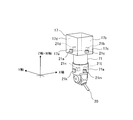
- FIG. 10 shows a part of the machine tool, in which 1 is a saddle, 2 is a ram supported by the saddle 1 so as to be movable in the Z-axis direction (vertical direction), and 3 is rotatable to the ram 2.
- the supported spindle 4 is a tool holder attached to the spindle, and 5 is a tool held by the tool holder 4.
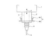
- a collision detection sensor 6 is attached to the ram 2.
- the collision detection sensor 6 includes a ring member holding portion 6A attached to the side surface of the ram 2 and a ring member 6B held by the ring member holding portion 6A.
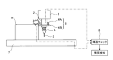
- FIG. 11 in this collision detection system, when the ring member 6B collides with the workpiece w placed on the table 7 due to an NC programming error or an operator's operation error, the ring member 6B and the workpiece w are displayed. As shown by the dotted line in FIG. Therefore, a collision can be detected by checking the continuity with the continuity check unit 8.
- Japanese Patent No. 2895316 JP 2012-58976 A Japanese Patent No. 3373352 Japanese Patent No. 3321604 Japanese Patent No. 4986840
- an object of the present invention is to provide an inexpensive machine tool collision avoidance system capable of avoiding a collision due to an operator's operation error or a probing error at the start of machining.
- a machine tool collision avoidance system that solves the above-described problem is a machine tool that includes a table on which a workpiece is placed, a moving body, and a moving shaft that linearly moves the moving body or the table.
- a collision avoidance system for avoiding a collision between the movable body and the workpiece A non-contact distance sensor that is attached to the movable body and detects a distance to the workpiece; Collision avoidance control means,
- the collision avoidance control means includes A collision determination unit that determines whether a sensor signal of the distance sensor is shorter than a distance setting value; When the collision determination unit determines that the sensor signal is shorter than the distance setting value, the collision determination unit includes a collision avoidance processing unit that performs a process of avoiding a collision between the moving body and the workpiece.
- a collision avoidance system for machine tools is the collision avoidance system for machine tools according to the first aspect, As the distance sensor, a first distance sensor attached to the moving body in the positive direction side of the moving shaft, and a second distance sensor attached to the moving body in the negative direction side of the moving shaft.
- the collision avoidance control means includes A movement direction determination unit that determines whether the movement direction of the moving body is a positive direction or a negative direction of the movement axis based on a movement command of the movement axis; When the moving direction determining unit determines that the moving direction of the moving body is the positive direction of the moving axis, the sensor signal of the first distance sensor is selected, and the moving direction determining unit determines the moving direction of the moving body.
- a sensor signal selection unit that selects a sensor signal of the second distance sensor when it is determined that the moving axis is in the negative direction;
- the sensor signal of the first distance sensor or the second distance sensor selected by the sensor signal selection unit is compared with the distance setting value, and the sensor signal is more than the distance setting value. It is characterized by determining whether it is short.
- a machine tool collision avoidance system is the machine tool collision avoidance system according to the first aspect, As the distance sensor, it has a distance sensor attached to either the positive direction side or the negative direction side of the moving axis in the moving body,
- the collision avoidance control means includes A movement direction determination unit that determines whether the movement direction of the moving body is a positive direction or a negative direction of the movement axis based on a movement command of the movement axis; When the distance sensor is attached to the positive direction side, when the moving direction determination unit determines that the moving direction of the moving body is the positive direction of the moving axis, the sensor signal of the distance sensor is And when the distance sensor is attached to the negative direction side, when the movement direction determination unit determines that the movement direction of the moving body is the negative direction of the movement axis, A sensor signal selection unit for selecting a sensor signal; The collision determination unit compares a sensor signal of the distance sensor selected by the sensor signal selection unit and the distance setting value to determine whether the sensor signal is shorter than the distance detection
- a collision avoidance system for machine tools is the collision avoidance system for machine tools according to any one of the first to third aspects of the invention, A first distance setting value, a second distance setting value shorter than the first distance setting value, and a third distance setting value shorter than the second distance setting value are set as the distance setting value,
- the collision avoidance processing unit includes a collision warning processing unit, a deceleration processing unit, and a stop processing unit,
- the collision determination unit determines whether the sensor signal is shorter than the first distance setting value, the second distance setting value, and the third distance setting value;
- the collision warning processor warns when the collision determination unit determines that the sensor signal is shorter than the first distance setting value,
- the deceleration processing unit decelerates the moving speed of the moving axis when the collision determination unit determines that the sensor signal is shorter than the second distance setting value,
- the stop processing unit stops the movement of the moving shaft when the collision determination unit determines that the sensor signal is shorter than the third distance setting value.
- the movement A collision avoidance system for avoiding a collision between a body and the workpiece comprising a non-contact type distance sensor attached to the movable body for detecting a distance to the workpiece, and a collision avoidance control means,
- the collision avoidance control unit determines whether the sensor signal of the distance sensor is shorter than a distance setting value, and determines that the sensor signal is shorter than the distance setting value in the collision determination unit.
- a collision avoidance processing unit that performs a process for avoiding a collision between the moving body and the workpiece.
- a sensor using a ring member is a contact type and may malfunction due to chips.
- a distance sensor is a non-contact type, there is no possibility of malfunction due to chips.
- the collision avoidance control means is configured to move the moving body based on a moving command of the moving shaft. Is a moving direction determining unit that determines whether the moving axis is a positive direction or a negative direction, and the moving direction determining unit determines that the moving direction of the moving body is the positive direction of the moving axis.
- the sensor signal of the second distance sensor is selected when the sensor signal of the sensor is selected and the moving direction determination unit determines that the moving direction of the moving body is the negative direction of the moving axis.
- the collision determination unit compares the distance setting value with the sensor signal of the first distance sensor or the second distance sensor selected by the sensor signal selection unit, Since it is characterized by determining whether a sensor signal is shorter than the said distance setting value, the collision by the operator's operation mistake or the probing mistake at the time of a process start can be avoided.
- the distance sensor since the distance sensor is used, three-dimensional data of the workpiece and machining simulation are unnecessary. Therefore, an inexpensive system with a low processing load can be realized.
- it recognizes the moving direction of the moving body with the distance sensor attached, and uses only the information (sensor signal) of the distance sensor attached to that direction side, so unnecessary false detection (collision detection in a direction other than the moving direction) Can be reduced.
- the collision avoidance control means determines whether the movement direction of the moving body is a positive direction or a negative direction of the movement axis based on a movement command of the movement axis.
- the direction determining unit and the distance sensor are attached to the positive direction side, the distance is determined when the moving direction determining unit determines that the moving direction of the moving body is the positive direction of the moving axis.
- the movement direction determination unit determines that the movement direction of the moving body is the negative direction of the movement axis.
- a sensor signal selection unit that selects a sensor signal of the distance sensor when the collision determination unit compares the sensor signal of the distance sensor selected by the sensor signal selection unit with the distance setting value. Then, since it is characterized in that it is determined whether or not the sensor signal is shorter than the distance detection value, it is possible to avoid a collision due to an operator's operation error or a probing error at the start of machining.
- the distance sensor since the distance sensor is used, three-dimensional data of the workpiece and machining simulation are unnecessary. Therefore, an inexpensive system with a low processing load can be realized.
- it recognizes the moving direction of the moving body with the distance sensor attached, and uses only the information (sensor signal) of the distance sensor attached to that direction side, so unnecessary false detection (collision detection in a direction other than the moving direction) Can be reduced.
- the first distance setting value and the first distance setting as the distance setting value A second distance setting value shorter than the second distance setting value and a third distance setting value shorter than the second distance setting value are set, and as the collision avoidance processing unit, a collision warning processing unit, a deceleration processing unit, and a stop processing unit
- the collision determination unit determines whether the sensor signal is shorter than the first distance setting value, the second distance setting value, and the third distance setting value, and the collision warning
- the processing unit warns when the collision determination unit determines that the sensor signal is shorter than the first distance setting value, and the deceleration processing unit outputs the second distance setting to the sensor signal in the collision determination unit.
- the stop processing unit stops the movement of the moving shaft when the collision determination unit determines that the sensor signal is shorter than the third distance setting value. Due to the feature, the collision avoidance process can be surely performed step by step in the order of warning, deceleration, and stop.
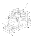
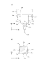
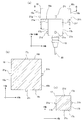
- FIG. 1 is an overall view of a machine tool including a machine tool collision avoidance system according to Embodiment 1 of the present invention. It is a figure which shows the attachment state of the ultrasonic sensor in the said collision avoidance system, (a) is a side view, (b) is the sectional view on the AA line of (a) (The structure in a ram is abbreviate
- Embodiment 1 A machine tool collision avoidance system according to Embodiment 1 of the present invention will be described with reference to FIGS.
- the illustrated machine tool 11 is a general portal machining center having a bed 12, a table 13, a portal column 14, a cross rail 15, a saddle 16, a ram 17, and a main shaft 18. Yes.
- a work w is placed on the table 13.
- the table 13 is installed on the bed 12, and along the rail 12 a arranged on the bed 12, the X-axis direction (the longitudinal direction of the machine tool 11) by the X-axis that is a linear movement axis, that is, X It can move linearly in the + direction (positive direction) and-direction (negative direction) of the axis.
- the column 14 is installed so as to straddle the bed 12.
- the cross rail 15 is installed on the front surface of the column 14, and along the rail 14 a disposed on the front surface of the column 14, the W axis direction (vertical direction), that is, the W axis is defined by the W axis that is a linear movement axis.
- the W axis is a parallel axis to the Z axis.
- the saddle 16 is installed on the front surface of the cross rail 15, and along the rail 15 a disposed on the front surface of the cross rail 15, the Y axis is a linear movement axis (Y-axis direction (the left-right direction of the machine tool 11)). ), That is, it can move linearly in the + direction (positive direction) and ⁇ direction (negative direction) of the Y-axis.
- the ram 17 is movably supported by the saddle 16 and is moved in the Z-axis direction (vertical direction) by the Z-axis, which is a linear movement axis, that is, in the positive direction (positive direction) and negative direction (negative direction) of the Z-axis. It can move linearly.
- the X-axis direction, the Y-axis direction, the Z-axis direction, and the W-axis direction are orthogonal to each other.
- the main shaft 18 is rotatably supported by the ram 17.
- a tool holder 19 is attached to the main shaft 18, and a tool 20 is held by the tool holder 19.
- the machine tool 11 includes ultrasonic sensors 21a to 21f that are non-contact distance sensors for configuring a collision avoidance system. It is attached.
- the ultrasonic sensors 21a, 21b, 21c, and 21d are respectively attached to the side surfaces 17a, 17b, 17c, and 17d of the ram 17, and the ultrasonic sensors 21e and 21f are attached to the lower surface 16e of the saddle 16. That is, the ultrasonic sensor 21a (second distance sensor) is attached to the negative direction side of the X axis in the ram 17, and detects the negative direction distance of the X axis.
- the ultrasonic sensor 21b (first distance sensor) is attached to the + direction side of the X axis in the ram 17 and detects the distance in the + direction of the X axis.
- the ultrasonic sensor 21c (second distance sensor) is attached to the negative direction side of the Y axis in the ram 17, and detects the negative direction distance of the Y axis.
- the ultrasonic sensor 21d (first distance sensor) is attached to the + direction side of the Y axis in the ram 17 and detects the distance in the + direction of the Y axis.
- the ultrasonic sensors 21e and 21f are attached to the negative direction side of the W axis in the saddle 16, and detect the distance in the negative direction of the W axis.
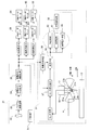
- the machine tool 11 includes an automatic operation by performing numerical control by an NC (numerical control) device 31 and a manual operation by operating an operation panel 51 of the NC (numerical control) device 31 by an operator. And can be done.
- the NC device 31 includes a program analysis processing unit 33, a movement command creation processing unit 34, and a movement command interpolation processing unit 35.
- the program analysis processing unit 33 analyzes the NC program 32 in which data relating to the approach to the workpiece w and the processing of the workpiece w is described.
- the NC program 32 also designates an area where the collision avoidance system operates.
- the movement command creation processing unit 34 creates movement commands for the X axis, Y axis, Z axis, and W axis based on the analysis result of the NC program 32 in the program analysis processing unit 33.
- the movement command interpolation processing unit 35 performs acceleration / deceleration interpolation processing on the X, Y, Z, and W axis movement commands created by the movement command creation processing unit 34, and then issues an X-axis movement command. It outputs to the X-axis servo amplifier 61, outputs a Y-axis movement command to the Y-axis servo amplifier 62, and outputs a W-axis movement command to the W-axis servo amplifier 63.
- illustration is abbreviate
- the operator operates the manual operation panel 51 to output an X-axis movement command from the manual operation panel 51 to the X-axis servo amplifier 61, and output a Y-axis movement command to the Y-axis servo amplifier 62.
- a W axis movement command is output to the W axis servo amplifier 63.
- the Z-axis movement command at the time of manual operation is not shown, but is the same as the case of the W-axis movement command.
- the X-axis servo amplifier 61 performs drive control of the X-axis servo motor 64 based on the X-axis movement command. As a result, the X-axis servomotor 64 drives the X-axis to move in the + or ⁇ direction, and the table 13 moves in the + or ⁇ direction of the X axis.
- the Y-axis servo amplifier 62 performs drive control of the Y-axis servo motor 65 based on the Y-axis movement command. As a result, the Y-axis servomotor 65 drives the Y-axis to move in the + or ⁇ direction, and the saddle 16 moves in the + or ⁇ direction of the Y axis.
- the ram 17 and the main shaft 18 (tool 20) move together with the saddle 16 in the + or ⁇ direction of the Y axis.
- the W axis servo amplifier 63 performs drive control of the W axis servo motor 66 based on the W axis movement command.
- the W-axis servomotor 66 drives the W-axis to move in the + or ⁇ direction, and the cross rail 15 moves in the + or ⁇ direction of the W axis.
- the saddle 16, the ram 17, and the main shaft 18 (tool 20) move together with the cross rail 15 in the + or-direction of the W axis.
- the Z-axis servo amplifier performs drive control of the Z-axis servo motor based on the Z-axis movement command.
- the Z-axis servomotor is driven to move the Z-axis in the + or ⁇ direction, and the ram 17 moves in the + or ⁇ direction of the Z axis.
- the main shaft 18 (tool 20) also moves along with the ram 17 in the + or ⁇ direction of the Z axis.
- the collision avoidance system is configured to include the NC device 31 that also functions as a collision avoidance control unit and the above-described ultrasonic sensors 21a to 21f.
- the NC device 31 includes a moving direction determination unit 36, a sensor signal selection unit 37, a collision determination unit 38, and a collision avoidance processing unit 39 as functional units as collision avoidance control means.
- the collision avoidance processing unit 39 includes a collision warning processing unit 40, a deceleration processing unit 41, and a stop processing unit 42.
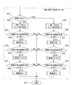
- each unit in the collision avoidance system will be described with reference to the flowcharts of FIGS.
- the details of the “processing flow unit related to the X axis” in the flowchart of FIG. 4 are shown in FIG. 5, the details of the “processing flow unit related to the Y axis” in the flowchart of FIG. 4 are shown in FIG.
- Details of the “processing flow unit relating to the W axis” are shown in FIG.
- each step in the flowcharts of FIGS. 4 to 7 is denoted by reference numerals such as S1 and S2.
- step S1 When the operation of the collision avoidance system is started (step S1), first, in step S2, it is determined whether the machine tool 21 is in automatic operation or manual operation. In step S2, it is determined whether the operation is manual operation or automatic operation according to the automatic determination based on the movement command or the operation mode switch of the operation panel 51. When it is determined in step 2 that it is a manual operation, the process proceeds to step S4, whereas when it is determined in step 2 that it is an automatic operation, the process proceeds to step S3. In step S ⁇ b> 3, based on the coordinate position of the tool 20, it is determined whether or not the tool 20 is located in a designated area designated by the NC program 32. When it is determined in step S3 that it is not located in the designated area, the process of the collision avoidance system is terminated (step S13). If it is determined in step S3 that it is located in the designated area, the process proceeds to step S4.
- step S4 the movement direction determination unit 36 first determines which movement axis is moving. This determination of the moving body is performed based on the X-axis movement command, the Y-axis movement command, and the W-axis movement command output from the NC device 31 or the manual operation panel 51.
- the X-axis movement command is output, it is determined that the X-axis is a movement axis.
- the Y-axis movement command is output, it is determined that the Y-axis is a movement axis, and the W-axis movement command is output. When it is, it is determined that the W axis is the moving axis.
- a plurality of movement commands may be output at the same time, and a plurality of movement axes (for example, the X-axis and the Y-axis) may move simultaneously.
- An axis (for example, X axis and Y axis) is determined.
- illustration is abbreviate
- step S4 If it is determined in step S4 that the X axis is a movement axis, the process proceeds to step S5. If it is determined that the Y axis is a movement axis, the process proceeds to step S21. If it is determined that the W axis is a movement axis, the process proceeds to step S36. .
- step S5 the movement direction determination unit 36 determines that the movement direction of the ram 17 (moving body) is the + direction of the X axis based on the X axis movement command. Or-direction. In this case, it is the table 13 (work w) that actually moves along the X axis. However, since the ram 17 moves relative to the table 13 (work w), it is based on the X axis movement command. Thus, it is possible to determine whether the moving direction of the ram 17 (that is, the moving direction relative to the table 13 (work w)) is the positive direction or the negative direction of the X axis.
- step S5 If it is determined in step S5 that the moving direction of the ram 17 is the positive direction of the X axis, the process proceeds to step S6. If it is determined in step S5 that the moving direction of the ram 17 is the negative direction of the X axis, the process proceeds to step S14.
- step S6 the sensor signal selection unit 37 selects (acquires) the sensor signal of the ultrasonic sensor 21b, which is a sensor signal in the positive direction of the X axis. Thereafter, the process proceeds to step S7.
- step S7 the collision determination unit 38 compares the sensor signal (distance detection value) of the ultrasonic sensor 21b selected by the sensor signal selection unit 37 with the first distance set value, and the sensor signal of the ultrasonic sensor 21b is obtained. It is determined whether it is shorter than the first distance set value. When it is determined in step S7 that the sensor signal of the ultrasonic sensor 21b is not shorter than the first distance set value, the process of the collision avoidance system is ended (step S13).
- step S7 When it is determined in step S7 that the sensor signal of the ultrasonic sensor 21b is shorter than the first distance set value, the process proceeds to step S8.
- step S8 the collision warning processing unit 40 warns when the collision determination unit 38 determines that the sensor signal of the ultrasonic sensor 21b is shorter than the first distance set value (for example, generation of a warning sound or lighting of a warning lamp). ) Then, it progresses to step S9.
- step S9 the collision determination unit 38 obtains the sensor signal (distance detection value) of the ultrasonic sensor 21b selected by the sensor signal selection unit 37 and the second distance setting value set shorter than the first distance setting value. In comparison, it is determined whether the sensor signal of the ultrasonic sensor 21b is shorter than the second distance set value.
- step S9 When it is determined in step S9 that the sensor signal of the ultrasonic sensor 21b is not shorter than the second distance set value, the process of the collision avoidance system is ended (step S13).
- step S9 the process proceeds to step S10.
- step S10 the deceleration processing unit 41 decelerates the moving speed of the X axis when the collision determination unit 38 determines that the sensor signal of the ultrasonic sensor 21b is shorter than the second distance setting value. Then, it progresses to step S11.
- step S11 the collision determination unit 38 obtains the sensor signal (distance detection value) of the ultrasonic sensor 21b selected by the sensor signal selection unit 37 and the third distance setting value set to be shorter than the second distance setting value. In comparison, it is determined whether the sensor signal of the ultrasonic sensor 21b is shorter than the third distance set value. When it is determined in step S11 that the sensor signal of the ultrasonic sensor 21b is not shorter than the third distance setting value, the process of the collision avoidance system is ended (step S13). When it is determined in step S11 that the sensor signal of the ultrasonic sensor 21b is shorter than the third distance setting value, the process proceeds to step S12.
- step S12 the stop processing unit 42 stops the movement of the X axis when the collision determination unit 38 determines that the sensor signal of the ultrasonic sensor 21b is shorter than the third distance set value. Thereafter, the process of the collision avoidance system is terminated (step S13).
- step S14 the sensor signal selection unit 37 selects (acquires) a sensor signal of the ultrasonic sensor 21a that is a sensor signal in the negative direction of the X axis. Thereafter, the process proceeds to step S15.
- step S15 the collision determination unit 38 compares the sensor signal (distance detection value) of the ultrasonic sensor 21a selected by the sensor signal selection unit 37 with the first distance setting value, and the sensor signal of the ultrasonic sensor 21a. Is shorter than the first distance set value. When it is determined in step S15 that the sensor signal of the ultrasonic sensor 21a is not shorter than the first distance setting value, the process of the collision avoidance system is ended (step S13).
- step S15 When it is determined in step S15 that the sensor signal of the ultrasonic sensor 21a is shorter than the first distance set value, the process proceeds to step S16.
- step S16 the collision warning processing unit 40 warns when the collision determination unit 38 determines that the sensor signal of the ultrasonic sensor 21a is shorter than the first distance setting value (for example, generation of a warning sound or lighting of a warning lamp). ) Thereafter, the process proceeds to step S17.
- step S ⁇ b> 17 the collision determination unit 38 compares the sensor signal (distance detection value) of the ultrasonic sensor 21 a selected by the sensor signal selection unit 37 with the second distance setting value, and the sensor signal of the ultrasonic sensor 21 a. Is shorter than the second distance setting value.
- step S17 When it is determined in step S17 that the sensor signal of the ultrasonic sensor 21a is not shorter than the second distance setting value, the process of the collision avoidance system is ended (step S13).
- step S17 When it is determined in step S17 that the sensor signal of the ultrasonic sensor 21a is shorter than the second distance setting value, the process proceeds to step S18.
- step S18 the deceleration processing unit 41 decelerates the X-axis moving speed when the collision determination unit 38 determines that the sensor signal of the ultrasonic sensor 21a is shorter than the second distance setting value. Thereafter, the process proceeds to step S19.
- step S19 the collision determination unit 38 compares the sensor signal (distance detection value) of the ultrasonic sensor 21a selected by the sensor signal selection unit 37 with the third distance setting value, and the sensor signal of the ultrasonic sensor 21a. Is shorter than the third distance setting value.
- the process of the collision avoidance system is ended (step S13).
- step S19 the process proceeds to step S20.
- step S20 the stop processing unit 42 stops the movement of the X axis when the collision determination unit 38 determines that the sensor signal of the ultrasonic sensor 21a is shorter than the third distance setting value. Thereafter, the process of the collision avoidance system is terminated (step S13).
- step S21 the movement direction determination unit 36 determines that the movement direction of the ram 17 (moving body) is the + direction of the Y axis based on the Y axis movement command. Or-direction. If it is determined in step S21 that the moving direction of the ram 17 is the positive direction of the Y axis, the process proceeds to step S22. If it is determined in step S21 that the moving direction of the ram 17 is the negative direction of the Y axis, the process proceeds to step S29.
- step S22 the sensor signal selection unit 37 selects (acquires) the sensor signal of the ultrasonic sensor 21d, which is a sensor signal in the + direction of the Y axis. Thereafter, the process proceeds to step S23.
- step S23 the collision determination unit 38 compares the sensor signal (distance detection value) of the ultrasonic sensor 21d selected by the sensor signal selection unit 37 with the first distance setting value, and the sensor signal of the ultrasonic sensor 21d. Is shorter than the first distance set value. When it is determined in step S23 that the sensor signal of the ultrasonic sensor 21d is not shorter than the first distance setting value, the process of the collision avoidance system is ended (step S13).
- step S24 the collision warning processing unit 40 warns when the collision determination unit 38 determines that the sensor signal of the ultrasonic sensor 21d is shorter than the first distance setting value (for example, generation of a warning sound or lighting of a warning lamp). ) Thereafter, the process proceeds to step S25.
- step S25 the collision determination unit 38 compares the sensor signal (distance detection value) of the ultrasonic sensor 21d selected by the sensor signal selection unit 37 with the second distance setting value, and the sensor signal of the ultrasonic sensor 21d. Is shorter than the second distance setting value.
- step S25 When it is determined in step S25 that the sensor signal of the ultrasonic sensor 21d is not shorter than the second distance set value, the process of the collision avoidance system is ended (step S13).
- step S25 When it is determined in step S25 that the sensor signal of the ultrasonic sensor 21d is shorter than the second distance setting value, the process proceeds to step S26.
- step S26 the deceleration processing unit 41 decelerates the movement speed of the Y axis when the collision determination unit 38 determines that the sensor signal of the ultrasonic sensor 21d is shorter than the second distance setting value. Thereafter, the process proceeds to step S27.
- step S27 the collision determination unit 38 compares the sensor signal (distance detection value) of the ultrasonic sensor 21d selected by the sensor signal selection unit 37 with the third distance setting value, and the sensor signal of the ultrasonic sensor 21d. Is shorter than the third distance setting value.
- the process of the collision avoidance system is ended (step S13). If it is determined in step S27 that the sensor signal of the ultrasonic sensor 21d is shorter than the third distance set value, the process proceeds to step S28.
- step S28 the stop processing unit 42 stops the movement of the Y axis when the collision determination unit 38 determines that the sensor signal of the ultrasonic sensor 21d is shorter than the third distance setting value. Thereafter, the process of the collision avoidance system is terminated (step S13).
- step S29 the sensor signal selection unit 37 selects (acquires) a sensor signal of the ultrasonic sensor 21c, which is a negative Y-axis sensor signal. Then, it progresses to step S30.
- step S ⁇ b> 30 the collision determination unit 38 compares the sensor signal (distance detection value) of the ultrasonic sensor 21 c selected by the sensor signal selection unit 37 with the first distance setting value, and the sensor signal of the ultrasonic sensor 21 c. Is shorter than the first distance set value.
- the process of the collision avoidance system is ended (step S13).
- step S30 When it is determined in step S30 that the sensor signal of the ultrasonic sensor 21c is shorter than the first distance setting value, the process proceeds to step S31.
- step S31 the collision warning processing unit 40 warns when the collision determination unit 38 determines that the sensor signal of the ultrasonic sensor 21c is shorter than the first distance setting value (for example, generation of a warning sound or lighting of a warning lamp). ) Thereafter, the process proceeds to step S32.
- step S ⁇ b> 32 the collision determination unit 38 compares the sensor signal (distance detection value) of the ultrasonic sensor 21 c selected by the sensor signal selection unit 37 with the second distance setting value, and the sensor signal of the ultrasonic sensor 21 c. Is shorter than the second distance setting value.
- step S32 When it is determined in step S32 that the sensor signal of the ultrasonic sensor 21c is not shorter than the second distance set value, the process of the collision avoidance system is ended (step S13).
- step S32 When it is determined in step S32 that the sensor signal of the ultrasonic sensor 21c is shorter than the second distance setting value, the process proceeds to step S33.
- step S33 the deceleration processing unit 41 decelerates the movement speed of the Y axis when the collision determination unit 38 determines that the sensor signal of the ultrasonic sensor 21c is shorter than the second distance setting value. Thereafter, the process proceeds to step S34.
- step S ⁇ b> 34 the collision determination unit 38 compares the sensor signal (distance detection value) of the ultrasonic sensor 21 c selected by the sensor signal selection unit 37 with the third distance setting value, and the sensor signal of the ultrasonic sensor 21 c. Is shorter than the third distance setting value.
- the process of the collision avoidance system is ended (step S13).
- the process proceeds to step S35.
- step S35 the stop processing unit 42 stops the movement of the Y axis when the collision determination unit 38 determines that the sensor signal of the ultrasonic sensor 21c is shorter than the third distance setting value. Thereafter, the process of the collision avoidance system is terminated (step S13).
- step S4 When it is determined in step S4 that the W axis (the axis that moves the saddle 16 in the W axis direction together with the cross rail 15) is the movement axis, first, in step S36, the movement direction determination unit 36 based on the W axis movement command. It is determined whether the movement direction of the saddle 16 is the positive direction or negative direction of the W axis. When it is determined in step S36 that the movement direction of the saddle 16 is the positive direction of the W axis, the process of the collision avoidance system is terminated (step S13). In step S36, the movement direction of the saddle 16 is the negative direction of the W axis. If determined, the process proceeds to step S37.
- step S37 the sensor signal selection unit 37 selects (acquires) the sensor signals of the ultrasonic sensors 21e and 21f, which are sensor signals in the negative direction of the W axis. Thereafter, the process proceeds to step S38.
- step S38 the collision determination unit 38 compares the sensor signals (distance detection values) of the ultrasonic sensors 21e and 21f selected by the sensor signal selection unit 37 with the first distance setting value, thereby comparing the ultrasonic sensors 21e, It is determined whether the sensor signal 21f is shorter than the first distance setting value.
- step S13 the process of the collision avoidance system is ended (step S13).
- step S38 When it is determined in step S38 that the sensor signals of the ultrasonic sensors 21e and 21f are shorter than the first distance set value, the process proceeds to step S39.
- step S39 the collision warning processing unit 40 warns when the collision determination unit 38 determines that the sensor signals of the ultrasonic sensors 21e and 21f are shorter than the first distance set value (for example, generation of a warning sound or warning lamp). Lighting). Thereafter, the process proceeds to step S40.
- step S40 the collision determination unit 38 compares the sensor signals (distance detection values) of the ultrasonic sensors 21e and 21f selected by the sensor signal selection unit 37 with the second distance setting value, thereby comparing the ultrasonic sensors 21e and 21f. It is determined whether the sensor signal 21f is shorter than the second distance setting value.
- step S40 When it is determined in step S40 that the sensor signals of the ultrasonic sensors 21e and 21f are not shorter than the second distance set value, the process of the collision avoidance system is ended (step S13).
- step S40 the process proceeds to step S41.
- step S41 the deceleration processing unit 41 decelerates the moving speed of the W axis when the collision determination unit 38 determines that the sensor signals of the ultrasonic sensors 21e and 21f are shorter than the second distance setting value. Thereafter, the process proceeds to step S42.
- step S42 the collision determination unit 38 compares the sensor signals (distance detection values) of the ultrasonic sensors 21e and 21f selected by the sensor signal selection unit 37 with the third distance setting value, thereby comparing the ultrasonic sensors 21e, It is determined whether the sensor signal 21f is shorter than the third distance setting value.
- step S42 the process of the collision avoidance system is ended (step S13).
- step S43 the process proceeds to step S43.
- step S43 the stop processing unit 42 stops the movement of the W axis when the collision determination unit 38 determines that the sensor signals of the ultrasonic sensors 21e and 21f are shorter than the third distance set value. Thereafter, the process of the collision avoidance system ends (step S13).
- the table 13 on which the workpiece w is placed the moving body (ram 17, saddle 16), and the moving body (ram 17, saddle 16).
- the moving body (ram 17, saddle 16) is moved linearly.
- the collision between the moving body (ram 17, saddle 16) and the workpiece w is avoided.
- a collision avoidance system which is a non-contact type distance sensor (ultrasonic sensors 21a to 21f) that detects a distance to a workpiece w attached to a moving body (ram 17, saddle 16), and collision avoidance control means (NC device) 31), and the collision avoidance control means (NC device 31) is configured such that the sensor signals of the distance sensors (ultrasonic sensors 21a to 21f) are distance set values (first distance set value, second distance set value, (3rd distance setting value)
- a collision determination unit 38 that determines whether or not the distance is shorter, and when the collision determination unit 38 determines that the sensor signal is shorter than the distance setting value, the moving body (ram 17, saddle 16) and workpiece w Since the apparatus has a collision avoidance processing unit 39 that performs a process for avoiding a collision, it is possible to avoid a collision due to an operator's operation error or a probing error at the start of machining.
- the distance sensors (ultrasonic sensors 21a to 21f) are used, three-dimensional data of the workpiece w and machining simulation are not necessary. Therefore, an inexpensive system with a low processing load can be realized. Further, a sensor using a ring member is a contact type and may malfunction due to chips, but the distance sensors (ultrasonic sensors 21a to 21f) are non-contact type, and therefore may malfunction due to chips. Absent.
- a distance sensor (ultrasonic sensor)
- a first distance sensor (ultrasonic sensors 21b, 21d) attached to the + direction side of the movement axis (X axis, Y axis) in the moving body (ram 17);
- a second distance sensor (ultrasonic sensors 21a, 21c) attached to the negative direction side of the movement axis (X axis, Y axis) of the moving body (ram 17), and collision avoidance control means (NC device) 31) is a movement for determining whether the moving direction of the moving body (ram 17) is the positive direction or the negative direction of the moving axis (X axis, Y axis) based on the movement command of the moving axis (X axis, Y axis).
- the direction determining unit 36 and the moving direction determining unit 36 determine that the moving direction of the moving body (ram 17) is the + direction of the moving axis (X axis, Y axis)
- the first distance sensor (ultrasonic sensor 21b, 21d) is selected, and the movement direction determination unit 36 is selected.
- a sensor signal for selecting the sensor signal of the second distance sensor (ultrasonic sensors 21a, 21c).
- the collision determination unit 38 includes a first distance sensor (ultrasonic sensors 21b and 21d) or a second distance sensor (ultrasonic sensors 21a and 21c) selected by the sensor signal selection unit 37.
- a signal is compared with a distance setting value (first distance setting value, second distance setting value, third distance setting value) to determine whether or not the sensor signal is shorter than the distance setting value. Therefore, the moving direction of the moving body (ram 17) to which the distance sensor (ultrasonic sensors 21a to 21d) is attached is recognized, and the distance sensor (ultrasonic sensors 21a, 21c or ultrasonic waves attached to the direction side) is recognized.
- Capacitors 21b, 21d) of the information (sensor signal) alone is used. For this reason, unnecessary false detection (collision detection in a direction other than the moving direction) can be reduced.
- the distance sensor includes distance sensors (ultrasonic sensors 21e and 21f) attached to the negative direction side of the moving axis (W axis) of the moving body (saddle 16), thereby avoiding collision.
- the control means determines whether the moving direction of the moving body (saddle 16) is the + direction or the-direction of the moving axis (W axis) based on the moving command of the moving axis (W axis).
- the determination unit 36 and the movement direction determination unit 36 determine that the moving direction of the moving body (saddle 16) is the negative direction of the moving axis (W axis)
- the sensor signal of the distance sensor (ultrasonic sensors 21e and 21f).
- the collision determination unit 38 includes a sensor signal of the distance sensor (ultrasonic sensors 21e and 21f) selected by the sensor signal selection unit 37 and a distance setting value (first distance setting). Value, second distance And the distance sensor (ultrasonic sensors 21e, 21f) is used to determine whether the sensor signal is shorter than the distance detection value. Since the moving direction of the attached moving body (saddle 16) is recognized and only information (sensor signals) of distance sensors (ultrasonic sensors 21e, 21f) attached to the direction is used, unnecessary false detection (movement) Collision detection in a direction other than the direction) can be reduced.
- the first distance setting value, the second distance setting value, and the third distance setting value are set as the distance setting values, and the collision warning processing unit 40, the deceleration processing unit 41, and the stop as the collision avoidance processing unit 39
- the collision determination unit 38 determines whether the sensor signal is shorter than the first distance setting value, the second distance setting value, and the third distance setting value, and the collision warning processing unit. In 40, when the collision determination unit 38 determines that the sensor signal is shorter than the first distance set value, a warning is given.
- the deceleration processing unit 41 when the sensor signal is shorter than the second distance set value, When the determination is made, the moving speed of the moving axis (X axis, Y axis, or W axis) is reduced, and the stop processing unit 42 determines that the collision determination unit 38 determines that the sensor signal is shorter than the third distance setting value. Movement of movement axis (X axis, Y axis or W axis) Because it is characterized in that stops, the collision avoidance processing alerts, deceleration can be carried out in stages to ensure the order of stops.
- Embodiment 2 Based on FIG. 8, a collision avoidance system for machine tools according to Embodiment 2 of the present invention will be described.
- an ultrasonic sensor 21a arranged as in the first embodiment is used as a non-contact distance sensor constituting the system.
- ultrasonic sensors 21 g to 21 j are also provided.
- the ultrasonic sensors 21g, 21h, 21i, and 21j are attached to the side surfaces 16a, 16b, 16c, and 16d of the saddle 16, respectively. That is, the ultrasonic sensor 21g (second distance sensor) is attached to the saddle 16 on the negative direction side of the X axis, and detects the distance in the negative direction of the X axis.
- the ultrasonic sensor 21h (first distance sensor) is attached to the + direction side of the X axis in the saddle 16, and detects the distance in the + direction of the X axis.
- the ultrasonic sensor 21i (second distance sensor) is attached to the negative direction side of the Y axis in the saddle 16, and detects the negative direction distance of the Y axis.
- the ultrasonic sensor 21j (first distance sensor) is attached to the saddle 16 on the + direction side of the Y axis, and detects the distance in the + direction of the Y axis.
- the processing contents of the collision avoidance system using the sensor signals (distance detection values) of the ultrasonic sensors 21g to 21j are the same as those in the first embodiment (FIGS. 3 to 7) (with regard to the processing contents).
- the ultrasonic sensor 21g corresponds to the ultrasonic sensor 21a
- the ultrasonic sensor 21h corresponds to the ultrasonic sensor 21b
- the ultrasonic sensor 21i corresponds to the ultrasonic sensor 21c
- the ultrasonic sensor 21j corresponds to the ultrasonic sensor 21d.
- the description and illustration are omitted here.
- the same effects as the collision avoidance system according to the first embodiment can be obtained.
- the saddle 16 can be reliably avoided from colliding.
- an attachment 71 is attached to the main shaft 18, and the tool 20 is attached to the attachment 71.
- the non-contact type distance sensor constituting the system is used. Ultrasonic sensors 21k to 21n are also provided.
- the ultrasonic sensors 21k, 21l, 21m, and 21n are attached to the respective portions of the side surface 71a of the attachment 71.
- the ultrasonic sensor 21k (second distance sensor) is attached to the negative direction side of the X axis in the attachment 71, and detects the negative distance of the X axis.
- the ultrasonic sensor 21l (first distance sensor) is attached to the + direction side of the X axis in the attachment 71, and detects the distance in the + direction of the X axis.
- the ultrasonic sensor 21m (second distance sensor) is attached to the negative direction side of the Y axis in the attachment 71, and detects the negative direction distance of the Y axis.
- the ultrasonic sensor 21n (first distance sensor) is attached to the + direction side of the Y axis in the attachment 71, and detects the distance in the + direction of the Y axis.
- the ultrasonic sensor 21k corresponds to the ultrasonic sensor 21a
- the ultrasonic sensor 21l corresponds to the ultrasonic sensor 21b
- the ultrasonic sensor 21m corresponds to the ultrasonic sensor 21c
- the ultrasonic sensor 21n corresponds to the ultrasonic sensor 21d.
- the description and illustration are omitted here.
- the same effects as the collision avoidance system according to the first embodiment can be obtained.
- the collision of the attachment 71 can be reliably avoided.
- the present invention relates to a collision avoidance system for machine tools, and is useful when applied to avoid a collision due to an operator's operation error or a probing error at the start of machining.
Abstract
例えば、ワークwが載置されたテーブル(13)と、移動体(ラム(17)、サドル(16))と、移動体又はテーブルを直線的に移動させる移動軸(X軸、Y軸、Z軸、W軸)とを有する工作機械において、移動体とワークとの衝突を回避する衝突回避システムであって、移動体に取り付けられワークまでの距離を検出する非接触式の距離センサ(超音波センサ(21a)~(21f))と、衝突回避制御手段(NC装置(31))とを有しており、衝突回避制御手段は、距離センサのセンサ信号が距離設定値よりも短いか否かを判定する衝突判定部(38)と、衝突判定部において前記センサ信号が前記距離設定値よりも短いと判定したとき、移動体とワークとの衝突を回避する処理を行う衝突回避処理部(39)とを有する構成とする。
Description
本発明は工作機械の衝突回避システムに関し、具体的にはワークが載置されたテーブルと、移動体(ラム、サドルなど)と、前記移動体又は前記テーブルを直線的に移動させる移動軸(X軸、Y軸、Z軸、W軸など)とを有する工作機械において、前記移動体と前記ワークとの衝突を回避する衝突回避システムに関する。
工作機械では、NCプログラミングによりワークの加工が行われるが、その際、
(1)NCプログラミングのミス
(2)工具の装着ミス
(3)ワークの段取りミス
(4)オペレータの操作ミス
等により、過大な切込みや、早送りでの工作機械の工具や移動体(ラム、サドルなど)とワークとの間での衝突が発生する。
(1)NCプログラミングのミス
(2)工具の装着ミス
(3)ワークの段取りミス
(4)オペレータの操作ミス
等により、過大な切込みや、早送りでの工作機械の工具や移動体(ラム、サドルなど)とワークとの間での衝突が発生する。
その対策として、各社より例えば下記の特許文献1~5に開示されているようなシステムが提案されている。
下記の特許文献1,2で提案されているものは、ワークの3次元形状を測定し、加工シュミュレーションを行うことにより工作機械の工具や移動体とワークとの衝突を検知するシステムである。
一方で、上記特許文献1,2の方法では高価なシステムとなるため、安価なシステムとして下記の特許文献3~5が提案されている。
下記の特許文献1,2で提案されているものは、ワークの3次元形状を測定し、加工シュミュレーションを行うことにより工作機械の工具や移動体とワークとの衝突を検知するシステムである。
一方で、上記特許文献1,2の方法では高価なシステムとなるため、安価なシステムとして下記の特許文献3~5が提案されている。
図10及び図11には従来の安価な衝突検知システムの例を示す。図10には工作機械の一部を示しており、同図において1はサドル、2はZ軸方向(鉛直方向)へ移動可能にサドル1に支持されたラム、3はラム2に回転可能に支持された主軸、4は主軸に装着された工具ホルダ、5は工具ホルダ4に保持された工具である。
そして、ラム2には衝突検知センサ6が取り付けられている。衝突検知センサ6は、ラム2の側面に取り付けられたリング部材保持部6Aと、このリング部材保持部6Aに保持されたリング部材6Bとから成るものである。
図11に示すように、本衝突検知システムではNCプログラミングのミスやオペレータの操作ミスなどにより、リング部材6Bがテーブル7に載置されたワークwに衝突すると、リング部材6Bとワークwなどが図11に点線で示すように電気的に導通する。従って、この導通を導通チェック部8でチェックすることにより衝突を検知することができる。
図11に示すように、本衝突検知システムではNCプログラミングのミスやオペレータの操作ミスなどにより、リング部材6Bがテーブル7に載置されたワークwに衝突すると、リング部材6Bとワークwなどが図11に点線で示すように電気的に導通する。従って、この導通を導通チェック部8でチェックすることにより衝突を検知することができる。
ところで、実際の加工現場における衝突ケースとしては、
(1) オペレータの操作ミス
(2) 加工開始時のアプローチミス
による衝突が多い。従って、これらの衝突ケースに限定すれば、非常に安価な衝突回避システムを実現することができる。
(1) オペレータの操作ミス
(2) 加工開始時のアプローチミス
による衝突が多い。従って、これらの衝突ケースに限定すれば、非常に安価な衝突回避システムを実現することができる。
従って本発明は上記の事情に鑑み、オペレータの操作ミスや加工開始時のプローチミスによる衝突を回避することができる安価な工作機械の衝突回避システムを提供することを課題とする。
上記課題を解決する第1発明の工作機械の衝突回避システムは、ワークが載置されたテーブルと、移動体と、前記移動体又は前記テーブルを直線的に移動させる移動軸とを有する工作機械において、前記移動体と前記ワークとの衝突を回避する衝突回避システムであって、
前記移動体に取り付けられ前記ワークまでの距離を検出する非接触式の距離センサと、
衝突回避制御手段とを有しており、
前記衝突回避制御手段は、
前記距離センサのセンサ信号が距離設定値よりも短いか否かを判定する衝突判定部と、
前記衝突判定部において前記センサ信号が前記距離設定値よりも短いと判定したとき、前記移動体と前記ワークとの衝突を回避する処理を行う衝突回避処理部とを有することを特徴とする。
前記移動体に取り付けられ前記ワークまでの距離を検出する非接触式の距離センサと、
衝突回避制御手段とを有しており、
前記衝突回避制御手段は、
前記距離センサのセンサ信号が距離設定値よりも短いか否かを判定する衝突判定部と、
前記衝突判定部において前記センサ信号が前記距離設定値よりも短いと判定したとき、前記移動体と前記ワークとの衝突を回避する処理を行う衝突回避処理部とを有することを特徴とする。
また、第2発明の工作機械の衝突回避システムは、第1発明の工作機械の衝突回避システムにおいて、
前記距離センサとして、前記移動体における前記移動軸の正方向側に取り付けられた第1距離センサと、前記移動体における前記移動軸の負方向側に取り付けられた第2距離センサとを有しており、
前記衝突回避制御手段は、
前記移動軸の移動指令に基づいて前記移動体の移動方向が、前記移動軸の正方向か負方向かを判定する移動方向判定部と、
前記移動方向判定部において前記移動体の移動方向が前記移動軸の正方向であると判定したときには前記第1距離センサのセンサ信号を選択し、前記移動方向判定部において前記移動体の移動方向が前記移動軸の負方向であると判定したときには前記第2距離センサのセンサ信号を選択するセンサ信号選択部とを有し、
前記衝突判定部では、前記センサ信号選択部で選択された前記第1距離センサ又は前記第2距離センサのセンサ信号と前記距離設定値とを比較して、前記センサ信号が前記距離設定値よりも短いか否かを判定することを特徴とする。
また、第3発明の工作機械の衝突回避システムは、第1発明の工作機械の衝突回避システムにおいて、
前記距離センサとして、前記移動体における前記移動軸の正方向側又は負方向側の何れか一方に取り付けられた距離センサを有しており、
前記衝突回避制御手段は、
前記移動軸の移動指令に基づいて前記移動体の移動方向が、前記移動軸の正方向か負方向かを判定する移動方向判定部と、
前記距離センサが前記正方向側に取り付けられている場合には、前記移動方向判定部において前記移動体の移動方向が前記移動軸の正方向であると判定したときに前記距離センサのセンサ信号を選択し、前記距離センサが前記負方向側に取り付けられている場合には、前記移動方向判定部において前記移動体の移動方向が前記移動軸の負方向であると判定したときに前記距離センサのセンサ信号を選択するセンサ信号選択部とを有し、
前記衝突判定部では、前記センサ信号選択部で選択された前記距離センサのセンサ信号と前記距離設定値とを比較して、前記センサ信号が前記距離検出値よりも短いか否かを判定することを特徴とする。
また、第4発明の工作機械の衝突回避システムは、第1~第3発明の何れか1つの工作機械の衝突回避システムにおいて、
前記距離設定値として第1距離設定値と、前記第1距離設定値よりも短い第2距離設定値と、前記第2距離設定値よりも短い第3距離設定値とが設定され、
前記衝突回避処理部として衝突警告処理部と、減速処理部と、停止処理部とを有しており、
前記衝突判定部では前記センサ信号が、前記第1距離設定値、前記第2距離設定値、前記第3距離設定値よりも短いか否かを判定し、
前記衝突警告処理部では、前記衝突判定部において前記センサ信号が前記第1距離設定値よりも短いと判定したときに警告し、
前記減速処理部では、前記衝突判定部において前記センサ信号が前記第2距離設定値よりも短いと判定したときに前記移動軸の移動速度を減速し、
前記停止処理部では、前記衝突判定部において前記センサ信号が前記第3距離設定値よりも短いと判定したときに前記移動軸の移動を停止することを特徴とする。
第1発明の工作機械の衝突回避システムによれば、ワークが載置されたテーブルと、移動体と、前記移動体又は前記テーブルを直線的に移動させる移動軸とを有する工作機械において、前記移動体と前記ワークとの衝突を回避する衝突回避システムであって、前記移動体に取り付けられ前記ワークまでの距離を検出する非接触式の距離センサと、衝突回避制御手段とを有しており、前記衝突回避制御手段は、前記距離センサのセンサ信号が距離設定値よりも短いか否かを判定する衝突判定部と、前記衝突判定部において前記センサ信号が前記距離設定値よりも短いと判定したとき、前記移動体と前記ワークとの衝突を回避する処理を行う衝突回避処理部とを有することを特徴としているため、オペレータの操作ミスや加工開始時のプローチミスによる衝突を回避することができる。
また、距離センサを用いるため、ワークの3次元データや、加工シミュレーションが不要である。そのため、安価で処理負担の低いシステムを実現することができる。
また、リング部材を用いたセンサは接触式で切粉などにより誤作動するおそれがあるが、距離センサは非接触式であるため切粉などによって誤作動するおそれがない。
また、距離センサを用いるため、ワークの3次元データや、加工シミュレーションが不要である。そのため、安価で処理負担の低いシステムを実現することができる。
また、リング部材を用いたセンサは接触式で切粉などにより誤作動するおそれがあるが、距離センサは非接触式であるため切粉などによって誤作動するおそれがない。
第2発明の工作機械の衝突回避システムによれば、第1発明の工作機械の衝突回避システムにおいて、前記距離センサとして、前記移動体における前記移動軸の正方向側に取り付けられた第1距離センサと、前記移動体における前記移動軸の負方向側に取り付けられた第2距離センサとを有しており、前記衝突回避制御手段は、前記移動軸の移動指令に基づいて前記移動体の移動方向が、前記移動軸の正方向か負方向かを判定する移動方向判定部と、前記移動方向判定部において前記移動体の移動方向が前記移動軸の正方向であると判定したときには前記第1距離センサのセンサ信号を選択し、前記移動方向判定部において前記移動体の移動方向が前記移動軸の負方向であると判定したときには前記第2距離センサのセンサ信号を選択するセンサ信号選択部とを有し、前記衝突判定部では、前記センサ信号選択部で選択された前記第1距離センサ又は前記第2距離センサのセンサ信号と前記距離設定値とを比較して、前記センサ信号が前記距離設定値よりも短いか否かを判定することを特徴としているため、オペレータの操作ミスや加工開始時のプローチミスによる衝突を回避することができる。
また、距離センサを用いるため、ワークの3次元データや、加工シミュレーションが不要である。そのため、安価で処理負担の低いシステムを実現することができる。
また、距離センサを取り付けた移動体の移動方向を認識して、その方向側に取り付けられた距離センサの情報(センサ信号)のみを用いるため、不要な誤検知(移動方向でない方向の衝突検知)を低減することができる。
また、距離センサを用いるため、ワークの3次元データや、加工シミュレーションが不要である。そのため、安価で処理負担の低いシステムを実現することができる。
また、距離センサを取り付けた移動体の移動方向を認識して、その方向側に取り付けられた距離センサの情報(センサ信号)のみを用いるため、不要な誤検知(移動方向でない方向の衝突検知)を低減することができる。
第3発明の工作機械の衝突回避システムによれば、第1発明の工作機械の衝突回避システムにおいて、前記距離センサとして、前記移動体における前記移動軸の正方向側又は負方向側の何れか一方に取り付けられた距離センサを有しており、前記衝突回避制御手段は、前記移動軸の移動指令に基づいて前記移動体の移動方向が、前記移動軸の正方向か負方向かを判定する移動方向判定部と、前記距離センサが前記正方向側に取り付けられている場合には、前記移動方向判定部において前記移動体の移動方向が前記移動軸の正方向であると判定したときに前記距離センサのセンサ信号を選択し、前記距離センサが前記負方向側に取り付けられている場合には、前記移動方向判定部において前記移動体の移動方向が前記移動軸の負方向であると判定したときに前記距離センサのセンサ信号を選択するセンサ信号選択部とを有し、前記衝突判定部では、前記センサ信号選択部で選択された前記距離センサのセンサ信号と前記距離設定値とを比較して、前記センサ信号が前記距離検出値よりも短いか否かを判定することを特徴としているため、オペレータの操作ミスや加工開始時のプローチミスによる衝突を回避することができる。
また、距離センサを用いるため、ワークの3次元データや、加工シミュレーションが不要である。そのため、安価で処理負担の低いシステムを実現することができる。
また、距離センサを取り付けた移動体の移動方向を認識して、その方向側に取り付けられた距離センサの情報(センサ信号)のみを用いるため、不要な誤検知(移動方向でない方向の衝突検知)を低減することができる。
また、距離センサを用いるため、ワークの3次元データや、加工シミュレーションが不要である。そのため、安価で処理負担の低いシステムを実現することができる。
また、距離センサを取り付けた移動体の移動方向を認識して、その方向側に取り付けられた距離センサの情報(センサ信号)のみを用いるため、不要な誤検知(移動方向でない方向の衝突検知)を低減することができる。
第4発明の工作機械の衝突回避システムによれば、第1~第3発明の何れか1つの工作機械の衝突回避システムにおいて、前記距離設定値として第1距離設定値と、前記第1距離設定値よりも短い第2距離設定値と、前記第2距離設定値よりも短い第3距離設定値とが設定され、前記衝突回避処理部として衝突警告処理部と、減速処理部と、停止処理部とを有しており、前記衝突判定部では前記センサ信号が、前記第1距離設定値、前記第2距離設定値、前記第3距離設定値よりも短いか否かを判定し、前記衝突警告処理部では、前記衝突判定部において前記センサ信号が前記第1距離設定値よりも短いと判定したときに警告し、前記減速処理部では、前記衝突判定部において前記センサ信号が前記第2距離設定値よりも短いと判定したときに前記移動軸の移動速度を減速し、前記停止処理部では、前記衝突判定部において前記センサ信号が前記第3距離設定値よりも短いと判定したときに前記移動軸の移動を停止することを特徴としているため、衝突回避処理を警告、減速、停止の順に段階的に確実に行うことができる。
以下、本発明の実施の形態例を図面に基づいて詳細に説明する。
<実施の形態例1>
図1~図7に基づき、本発明の実施の形態例1に係る工作機械の衝突回避システムについて説明する。
図1~図7に基づき、本発明の実施の形態例1に係る工作機械の衝突回避システムについて説明する。
まず、図1に基づき、本実施の形態例1の衝突回避システムを備えた工作機械11の全体的な構成の概要について説明する。
図示例の工作機械11は一般な門形マシニングセンタであり、ベッド12と、テーブル13と、門形のコラム14と、クロスレール15と、サドル16と、ラム17と、主軸18とを有している。
図示例の工作機械11は一般な門形マシニングセンタであり、ベッド12と、テーブル13と、門形のコラム14と、クロスレール15と、サドル16と、ラム17と、主軸18とを有している。
テーブル13にはワークwが載置される。テーブル13はベッド12上に設置されており、ベッド12上に配設されたレール12aに沿って、直線的な移動軸であるX軸によりX軸方向(工作機械11の前後方向)、即ちX軸の+方向(正方向)や-方向(負方向)に直線的に移動することができる。コラム14はベッド12を跨ぐようにして設置されている。
クロスレール15はコラム14の前面に設置されており、コラム14の前面に配設されたレール14aに沿って、直線的な移動軸であるW軸によりW軸方向(鉛直方向)、即ちW軸の+方向(正方向)や-方向(負方向)に直線的に移動することができる。W軸はZ軸に対して並行軸である。
サドル16はクロスレール15の前面に設置されており、クロスレール15の前面に配設されたレール15aに沿って、直線的な移動軸であるY軸によりY軸方向(工作機械11の左右方向)、即ちY軸の+方向(正方向)や-方向(負方向)に直線的に移動することができる。
ラム17はサドル16に移動可能に支持されており、直線的な移動軸であるZ軸によりZ軸方向(鉛直方向)、即ちZ軸の+方向(正方向)や-方向(負方向)に直線的に移動することができる。
なお、X軸方向と、Y軸方向と、Z軸方向及びW軸方向とは互いに直交している。主軸18はラム17に回転可能に支持されている。主軸18には工具ホルダ19が装着され、この工具ホルダ19によって工具20を保持している。
そして、図1、図2(a)及び図2(b)に示すように、工作機械11には、衝突回避システムを構成するための非接触式の距離センサである超音波センサ21a~21fが取り付けられている。
超音波センサ21a,21b,21c,21dはラム17の側面17a,17b,17c,17dにそれぞれ取り付けられ、超音波センサ21e,21fはサドル16の下面16eに取り付けられている。
即ち、超音波センサ21a(第2距離センサ)は、ラム17におけるX軸の-方向側に取り付けられており、X軸の-方向の距離を検出する。超音波センサ21b(第1距離センサ)は、ラム17におけるX軸の+方向側に取り付けられており、X軸の+方向の距離を検出する。超音波センサ21c(第2距離センサ)は、ラム17におけるY軸の-方向側に取り付けられており、Y軸の-方向の距離を検出する。超音波センサ21d(第1距離センサ)は、ラム17におけるY軸の+方向側に取り付けられており、Y軸の+方向の距離を検出する。超音波センサ21e,21fは、サドル16におけるW軸の-方向側に取り付けられており、W軸の-方向の距離を検出する。
即ち、超音波センサ21a(第2距離センサ)は、ラム17におけるX軸の-方向側に取り付けられており、X軸の-方向の距離を検出する。超音波センサ21b(第1距離センサ)は、ラム17におけるX軸の+方向側に取り付けられており、X軸の+方向の距離を検出する。超音波センサ21c(第2距離センサ)は、ラム17におけるY軸の-方向側に取り付けられており、Y軸の-方向の距離を検出する。超音波センサ21d(第1距離センサ)は、ラム17におけるY軸の+方向側に取り付けられており、Y軸の+方向の距離を検出する。超音波センサ21e,21fは、サドル16におけるW軸の-方向側に取り付けられており、W軸の-方向の距離を検出する。
次に、図3及び図4~図7に基づき、衝突回避システムの構成と処理フローについて説明する。
図3に示すように、工作機械11は、NC(数値制御)装置31によって数値制御を行うことによる自動運転と、NC(数値制御)装置31の操作盤51をオペレータが操作することによる手動運転とを行うことができる。
NC装置31はプログラム解析処理部33と、移動指令作成処理部34と、移動指令補間処理部35とを有している。
プログラム解析処理部33では、ワークwへのアプローチやワークwの加工の関するデータなどが記述されたNCプログラム32を解析する。なお、NCプログラム32には、衝突回避システムが動作する領域も指定されている。
移動指令作成処理部34では、プログラム解析処理部33におけるNCプログラム32の解析結果に基づき、X軸、Y軸、Z軸、W軸の移動指令を作成する。
移動指令補間処理部35では、移動指令作成処理部34で作成されたX軸、Y軸、Z軸、W軸の移動指令に対して加減速の補間処理を行った後、X軸移動指令をX軸サーボアンプ61へ出力し、Y軸移動指令をY軸サーボアンプ62へ出力し、W軸移動指令をW軸サーボアンプ63へ出力する。なお、Z軸移動指令に関しては、図示を省略しているが、W軸移動指令の場合と同様である。
手動運転時には、オペレータが手動操作盤51を操作することによって当該手動操作盤51から、X軸移動指令をX軸サーボアンプ61へ出力し、Y軸移動指令をY軸サーボアンプ62へ出力し、W軸移動指令をW軸サーボアンプ63へ出力する。なお、この手動運転時のZ軸移動指令に関しても、図示は省略しているが、W軸移動指令の場合と同様である。
X軸サーボアンプ61では、X軸移動指令に基づいてX軸サーボモータ64の駆動制御を行う。その結果、X軸サーボモータ64に駆動されてX軸が+方向又は-方向に移動し、テーブル13がX軸の+方向又は-方向に移動する。
Y軸サーボアンプ62では、Y軸移動指令に基づいてY軸サーボモータ65の駆動制御を行う。その結果、Y軸サーボモータ65に駆動されてY軸が+方向又は-方向に移動し、サドル16がY軸の+方向又は-方向に移動する。このときサドル16とともにラム17及び主軸18(工具20)もY軸の+方向又は-方向に移動する。
W軸サーボアンプ63では、W軸移動指令に基づいてW軸サーボモータ66の駆動制御を行う。その結果、W軸サーボモータ66に駆動されてW軸が+方向又は-方向に移動し、クロスレール15がW軸の+方向又は-方向に移動する。このときクロスレール15とともにサドル16、ラム17及び主軸18(工具20)もW軸の+方向又は-方向に移動する。
図示は省略するが、Z軸サーボアンプでは、Z軸移動指令に基づいてZ軸サーボモータの駆動制御を行う。その結果、Z軸サーボモータに駆動されてZ軸が+方向又は-方向に移動し、ラム17がZ軸の+方向又は-方向に移動する。このときラム17とともに主軸18(工具20)もZ軸の+方向又は-方向に移動する。
そして、本実施の形態例1の衝突回避システムは、衝突回避制御手段としても機能するNC装置31と、前述の超音波センサ21a~21fとを有する構成となっている。
NC装置31は衝突回避制御手段としての機能部として移動方向判定部36と、センサ信号選択部37と、衝突判定部38と、衝突回避処理部39とを有している。また、衝突回避処理部39は衝突警告処理部40と、減速処理部41と、停止処理部42とを有している。
NC装置31は衝突回避制御手段としての機能部として移動方向判定部36と、センサ信号選択部37と、衝突判定部38と、衝突回避処理部39とを有している。また、衝突回避処理部39は衝突警告処理部40と、減速処理部41と、停止処理部42とを有している。
この衝突回避システム(NC装置31)における各部の処理内容などを、図4~図7のフローチャートも参照して説明する。なお、図4のフローチャートにおける「X軸に関する処理フロー部」の詳細は図5に示し、図4のフローチャートにおける「Y軸に関する処理フロー部」の詳細は図6に示し、図4のフローチャートにおける「W軸に関する処理フロー部」の詳細は図7に示している。また、図4~図7のフローチャートにおける各ステップにはS1,S2などの符号を付した。
衝突回避システムの動作が開始されると(ステップS1)、まず、ステップS2において工作機械21が自動運転か手動運転かを判定する。ステップS2では、移動指令による自動判別もしくは操作盤51の運転モードスイッチに従って手動運転か自動運転かを判定する。ステップ2において手動運転であると判定したときにはステップS4へ進む一方、ステップ2において自動運転であると判定したときにはステップS3へ進む。
ステップS3では、工具20の座標位置に基づき、工具20がNCプログラム32で指定された指定領域に位置しているか否かを判定する。ステップS3において指定領域に位置していないと判定したときには衝突回避システムの処理を終了する(ステップS13)。ステップS3において指定領域に位置していると判定したときにはステップS4に進む。
ステップS3では、工具20の座標位置に基づき、工具20がNCプログラム32で指定された指定領域に位置しているか否かを判定する。ステップS3において指定領域に位置していないと判定したときには衝突回避システムの処理を終了する(ステップS13)。ステップS3において指定領域に位置していると判定したときにはステップS4に進む。
ステップS4において、移動方向判定部36では、まず、どの移動軸が移動しているかを判定する。この移動体の判定はNC装置31又は手動操作盤51から出力されるX軸移動指令、Y軸移動指令、W軸移動指令に基づいて行う。X軸移動指令が出力されているときにはX軸が移動軸であると判定し、Y軸移動指令が出力されているときにはY軸が移動軸であると判定し、W軸移動指令が出力されているときにはW軸が移動軸であると判定する。なお、複数の移動指令(例えばX軸移動指令とY軸移動指令)が同時に出力されて複数の移動軸(例えばX軸とY軸)が同時に移動することもあり、この場合には複数の移動軸(例えばX軸とY軸)を判定する。なお、Z軸移動指令に関しては、図示を省略しているが、W軸移動指令の場合と同様である。
ステップS4においてX軸が移動軸であると判定したときにはステップS5へ進み、Y軸が移動軸であると判定したときにはステップS21へ進み、W軸が移動軸であると判定したときにはステップS36へ進む。
ステップS4においてX軸が移動軸であると判定したときには、まず、ステップS5において移動方向判定部36では、X軸移動指令に基づいてラム17(移動体)の移動方向が、X軸の+方向か-方向かを判定する。なお、この場合、X軸によって実際に移動するのはテーブル13(ワークw)であるが、このテーブル13(ワークw)に対して相対的にラム17が移動するため、X軸移動指令に基づいてラム17の移動方向(即ちテーブル13(ワークw)に対する相対的な移動方向)がX軸の+方向か-方向かを判定することができる。
ステップS5においてラム17の移動方向がX軸の+方向であると判定したときにはステップS6へ進み、ステップS5においてラム17の移動方向がX軸の-方向であると判定したときにはステップS14へ進む。
ステップS5においてラム17の移動方向がX軸の+方向であると判定したときにはステップS6へ進み、ステップS5においてラム17の移動方向がX軸の-方向であると判定したときにはステップS14へ進む。
ステップS6においてセンサ信号選択部37では、X軸の+方向のセンサ信号である超音波センサ21bのセンサ信号を選択(取得)する。その後、ステップS7へ進む。
ステップS7において衝突判定部38では、センサ信号選択部37で選択された超音波センサ21bのセンサ信号(距離検出値)と第1距離設定値とを比較して、超音波センサ21bのセンサ信号が前記第1距離設定値よりも短いか否かを判定する。ステップS7において超音波センサ21bのセンサ信号が前記第1距離設定値よりも短くないと判定したときには、衝突回避システムの処理を終了する(ステップS13)。ステップS7において超音波センサ21bのセンサ信号が前記第1距離設定値よりも短いと判定したときには、ステップS8へ進む。
ステップS8において衝突警告処理部40では、衝突判定部38において超音波センサ21bのセンサ信号が前記第1距離設定値よりも短いと判定したときに警告(例えば警告音の発生や警告ランプの点灯等)する。その後、ステップS9へ進む。
ステップS9において衝突判定部38では、センサ信号選択部37で選択された超音波センサ21bのセンサ信号(距離検出値)と、第1距離設定値よりも短く設定された第2距離設定値とを比較して、超音波センサ21bのセンサ信号が前記第2距離設定値よりも短いか否かを判定する。ステップS9において超音波センサ21bのセンサ信号が前記第2距離設定値よりも短くないと判定したときには、衝突回避システムの処理を終了する(ステップS13)。ステップS9において超音波センサ21bのセンサ信号が前記第2距離設定値よりも短いと判定したときには、ステップS10へ進む。
ステップS10において減速処理部41では、衝突判定部38において超音波センサ21bのセンサ信号が前記第2距離設定値よりも短いと判定したときにX軸の移動速度を減速する。その後、ステップS11へ進む。
ステップS11において衝突判定部38では、センサ信号選択部37で選択された超音波センサ21bのセンサ信号(距離検出値)と、第2距離設定値よりも短く設定された第3距離設定値とを比較して、超音波センサ21bのセンサ信号が前記第3距離設定値よりも短いか否かを判定する。ステップS11において超音波センサ21bのセンサ信号が前記第3距離設定値よりも短くないと判定したときには、衝突回避システムの処理を終了する(ステップS13)。ステップS11において超音波センサ21bのセンサ信号が前記第3距離設定値よりも短いと判定したときには、ステップS12へ進む。
ステップS12において停止処理部42では、衝突判定部38において超音波センサ21bのセンサ信号が前記第3距離設定値よりも短いと判定したときにX軸の移動を停止する。その後、衝突回避システムの処理を終了する(ステップS13)。
ステップS14においてセンサ信号選択部37では、X軸の-方向のセンサ信号である超音波センサ21aのセンサ信号を選択(取得)する。その後、ステップS15へ進む。
ステップS15において衝突判定部38では、センサ信号選択部37で選択された超音波センサ21aのセンサ信号(距離検出値)と前記第1距離設定値とを比較して、超音波センサ21aのセンサ信号が前記第1距離設定値よりも短いか否かを判定する。ステップS15において超音波センサ21aのセンサ信号が前記第1距離設定値よりも短くないと判定したときには、衝突回避システムの処理を終了する(ステップS13)。ステップS15において超音波センサ21aのセンサ信号が前記第1距離設定値よりも短いと判定したときには、ステップS16へ進む。
ステップS16において衝突警告処理部40では、衝突判定部38において超音波センサ21aのセンサ信号が前記第1距離設定値よりも短いと判定したときに警告(例えば警告音の発生や警告ランプの点灯等)する。その後、ステップS17へ進む。
ステップS17において衝突判定部38では、センサ信号選択部37で選択された超音波センサ21aのセンサ信号(距離検出値)と前記第2距離設定値とを比較して、超音波センサ21aのセンサ信号が前記第2距離設定値よりも短いか否かを判定する。ステップS17において超音波センサ21aのセンサ信号が前記第2距離設定値よりも短くないと判定したときには、衝突回避システムの処理を終了する(ステップS13)。ステップS17において超音波センサ21aのセンサ信号が前記第2距離設定値よりも短いと判定したときには、ステップS18へ進む。
ステップS18において減速処理部41では、衝突判定部38において超音波センサ21aのセンサ信号が前記第2距離設定値よりも短いと判定したときにX軸の移動速度を減速する。その後、ステップS19へ進む。
ステップS19において衝突判定部38では、センサ信号選択部37で選択された超音波センサ21aのセンサ信号(距離検出値)と前記第3距離設定値とを比較して、超音波センサ21aのセンサ信号が前記第3距離設定値よりも短いか否かを判定する。ステップS19において超音波センサ21aのセンサ信号が前記第3距離設定値よりも短くないと判定したときには、衝突回避システムの処理を終了する(ステップS13)。ステップS19において超音波センサ21aのセンサ信号が前記第3距離設定値よりも短いと判定したときには、ステップS20へ進む。
ステップS20において停止処理部42では、衝突判定部38において超音波センサ21aのセンサ信号が前記第3距離設定値よりも短いと判定したときにX軸の移動を停止する。その後、衝突回避システムの処理を終了する(ステップS13)。
ステップS4においてY軸が移動軸であると判定したときには、まず、ステップS21において移動方向判定部36では、Y軸移動指令に基づいてラム17(移動体)の移動方向が、Y軸の+方向か-方向かを判定する。ステップS21においてラム17の移動方向がY軸の+方向であると判定したときにはステップS22へ進み、ステップS21においてラム17の移動方向がY軸の-方向であると判定したときにはステップS29へ進む。
ステップS22においてセンサ信号選択部37では、Y軸の+方向のセンサ信号である超音波センサ21dのセンサ信号を選択(取得)する。その後、ステップS23へ進む。
ステップS23において衝突判定部38では、センサ信号選択部37で選択された超音波センサ21dのセンサ信号(距離検出値)と前記第1距離設定値とを比較して、超音波センサ21dのセンサ信号が前記第1距離設定値よりも短いか否かを判定する。ステップS23において超音波センサ21dのセンサ信号が前記第1距離設定値よりも短くないと判定したときには、衝突回避システムの処理を終了する(ステップS13)。ステップS23において超音波センサ21dのセンサ信号が前記第1距離設定値よりも短いと判定したときには、ステップS24へ進む。
ステップS24において衝突警告処理部40では、衝突判定部38において超音波センサ21dのセンサ信号が前記第1距離設定値よりも短いと判定したときに警告(例えば警告音の発生や警告ランプの点灯等)する。その後、ステップS25へ進む。
ステップS25において衝突判定部38では、センサ信号選択部37で選択された超音波センサ21dのセンサ信号(距離検出値)と前記第2距離設定値とを比較して、超音波センサ21dのセンサ信号が前記第2距離設定値よりも短いか否かを判定する。ステップS25において超音波センサ21dのセンサ信号が前記第2距離設定値よりも短くないと判定したときには、衝突回避システムの処理を終了する(ステップS13)。ステップS25において超音波センサ21dのセンサ信号が前記第2距離設定値よりも短いと判定したときには、ステップS26へ進む。
ステップS26において減速処理部41では、衝突判定部38において超音波センサ21dのセンサ信号が前記第2距離設定値よりも短いと判定したときにY軸の移動速度を減速する。その後、ステップS27へ進む。
ステップS27において衝突判定部38では、センサ信号選択部37で選択された超音波センサ21dのセンサ信号(距離検出値)と前記第3距離設定値とを比較して、超音波センサ21dのセンサ信号が前記第3距離設定値よりも短いか否かを判定する。ステップS27において超音波センサ21dのセンサ信号が前記第3距離設定値よりも短くないと判定したときには、衝突回避システムの処理を終了する(ステップS13)。ステップS27において超音波センサ21dのセンサ信号が前記第3距離設定値よりも短いと判定したときには、ステップS28へ進む。
ステップS28において停止処理部42では、衝突判定部38において超音波センサ21dのセンサ信号が前記第3距離設定値よりも短いと判定したときにY軸の移動を停止する。その後、衝突回避システムの処理を終了する(ステップS13)。
ステップS29においてセンサ信号選択部37では、Y軸の-方向のセンサ信号である超音波センサ21cのセンサ信号を選択(取得)する。その後、ステップS30へ進む。
ステップS30において衝突判定部38では、センサ信号選択部37で選択された超音波センサ21cのセンサ信号(距離検出値)と前記第1距離設定値とを比較して、超音波センサ21cのセンサ信号が前記第1距離設定値よりも短いか否かを判定する。ステップS30において超音波センサ21cのセンサ信号が前記第1距離設定値よりも短くないと判定したときには、衝突回避システムの処理を終了する(ステップS13)。ステップS30において超音波センサ21cのセンサ信号が前記第1距離設定値よりも短いと判定したときには、ステップS31へ進む。
ステップS31において衝突警告処理部40では、衝突判定部38において超音波センサ21cのセンサ信号が前記第1距離設定値よりも短いと判定したときに警告(例えば警告音の発生や警告ランプの点灯等)する。その後、ステップS32へ進む。
ステップS32において衝突判定部38では、センサ信号選択部37で選択された超音波センサ21cのセンサ信号(距離検出値)と前記第2距離設定値とを比較して、超音波センサ21cのセンサ信号が前記第2距離設定値よりも短いか否かを判定する。ステップS32において超音波センサ21cのセンサ信号が前記第2距離設定値よりも短くないと判定したときには、衝突回避システムの処理を終了する(ステップS13)。ステップS32において超音波センサ21cのセンサ信号が前記第2距離設定値よりも短いと判定したときには、ステップS33へ進む。
ステップS33において減速処理部41では、衝突判定部38において超音波センサ21cのセンサ信号が前記第2距離設定値よりも短いと判定したときにY軸の移動速度を減速する。その後、ステップS34へ進む。
ステップS34において衝突判定部38では、センサ信号選択部37で選択された超音波センサ21cのセンサ信号(距離検出値)と前記第3距離設定値とを比較して、超音波センサ21cのセンサ信号が前記第3距離設定値よりも短いか否かを判定する。ステップS34において超音波センサ21cのセンサ信号が前記第3距離設定値よりも短くないと判定したときには、衝突回避システムの処理を終了する(ステップS13)。ステップS34において超音波センサ21cのセンサ信号が前記第3距離設定値よりも短いと判定したときには、ステップS35へ進む。
ステップS35において停止処理部42では、衝突判定部38において超音波センサ21cのセンサ信号が前記第3距離設定値よりも短いと判定したときにY軸の移動を停止する。その後、衝突回避システムの処理を終了する(ステップS13)。
ステップS4においてW軸(クロスレール15とともにサドル16をW軸方向へ移動する軸)が移動軸であると判定したときには、まず、ステップS36において移動方向判定部36では、W軸移動指令に基づいてサドル16の移動方向が、W軸の+方向か-方向かを判定する。ステップS36においてサドル16の移動方向がW軸の+方向であると判定したときには衝突回避システムの処理を終了し(ステップS13)、ステップS36においてサドル16の移動方向がW軸の-方向であると判定したときにはステップS37へ進む。
ステップS37においてセンサ信号選択部37では、W軸の-方向のセンサ信号である超音波センサ21e,21fのセンサ信号を選択(取得)する。その後、ステップS38へ進む。
ステップS38において衝突判定部38では、センサ信号選択部37で選択された超音波センサ21e,21fのセンサ信号(距離検出値)と前記第1距離設定値とを比較して、超音波センサ21e,21fのセンサ信号が前記第1距離設定値よりも短いか否かを判定する。ステップS38において超音波センサ21e,21fのセンサ信号が前記第1距離設定値よりも短くないと判定したときには、衝突回避システムの処理を終了する(ステップS13)。ステップS38において超音波センサ21e,21fのセンサ信号が前記第1距離設定値よりも短いと判定したときには、ステップS39へ進む。
ステップS39において衝突警告処理部40では、衝突判定部38において超音波センサ21e,21fのセンサ信号が前記第1距離設定値よりも短いと判定したときに警告(例えば警告音の発生や警告ランプの点灯等)する。その後、ステップS40へ進む。
ステップS40において衝突判定部38では、センサ信号選択部37で選択された超音波センサ21e,21fのセンサ信号(距離検出値)と前記第2距離設定値とを比較して、超音波センサ21e,21fのセンサ信号が前記第2距離設定値よりも短いか否かを判定する。ステップS40において超音波センサ21e,21fのセンサ信号が前記第2距離設定値よりも短くないと判定したときには、衝突回避システムの処理を終了する(ステップS13)。ステップS40において超音波センサ21e,21fのセンサ信号が前記第2距離設定値よりも短いと判定したときには、ステップS41へ進む。
ステップS41において減速処理部41では、衝突判定部38において超音波センサ21e,21fのセンサ信号が前記第2距離設定値よりも短いと判定したときにW軸の移動速度を減速する。その後、ステップS42へ進む。
ステップS42において衝突判定部38では、センサ信号選択部37で選択された超音波センサ21e,21fのセンサ信号(距離検出値)と前記第3距離設定値とを比較して、超音波センサ21e,21fのセンサ信号が前記第3距離設定値よりも短いか否かを判定する。ステップS42において超音波センサ21e,21fのセンサ信号が前記第3距離設定値よりも短くないと判定したときには、衝突回避システムの処理を終了する(ステップS13)。ステップS42において超音波センサ21e,21fのセンサ信号が前記第3距離設定値よりも短いと判定したときには、ステップS43へ進む。
ステップS43において停止処理部42では、衝突判定部38において超音波センサ21e,21fのセンサ信号が前記第3距離設定値よりも短いと判定したときにW軸の移動を停止する。その後、衝突回避システムの処理は終了する(ステップS13)。
以上のように、本実施の形態例1の衝突回避システムによれば、ワークwが載置されたテーブル13と、移動体(ラム17、サドル16)と、移動体(ラム17、サドル16)又はテーブル13を直線的に移動させる移動軸(X軸、Y軸、Z軸、W軸)とを有する工作機械11において、移動体(ラム17、サドル16)とワークwとの衝突を回避する衝突回避システムであって、移動体(ラム17、サドル16)に取り付けられワークwまでの距離を検出する非接触式の距離センサ(超音波センサ21a~21f)と、衝突回避制御手段(NC装置31)とを有しており、衝突回避制御手段(NC装置31)は、距離センサ(超音波センサ21a~21f)のセンサ信号が距離設定値(第1距離設定値、第2距離設定値、第3距離設定値)よりも短いか否かを判定する衝突判定部38と、衝突判定部38において前記センサ信号が前記距離設定値よりも短いと判定したとき、移動体(ラム17、サドル16)とワークwとの衝突を回避する処理を行う衝突回避処理部39とを有することを特徴としているため、オペレータの操作ミスや加工開始時のプローチミスによる衝突を回避することができる。
また、距離センサ(超音波センサ21a~21f)を用いるため、ワークwの3次元データや、加工シミュレーションが不要である。そのため、安価で処理負担の低いシステムを実現することができる。
また、リング部材を用いたセンサは接触式で切粉などにより誤作動するおそれがあるが、距離センサ(超音波センサ21a~21f)は非接触式であるため切粉などによって誤作動するおそれがない。
また、距離センサ(超音波センサ21a~21f)を用いるため、ワークwの3次元データや、加工シミュレーションが不要である。そのため、安価で処理負担の低いシステムを実現することができる。
また、リング部材を用いたセンサは接触式で切粉などにより誤作動するおそれがあるが、距離センサ(超音波センサ21a~21f)は非接触式であるため切粉などによって誤作動するおそれがない。
更には、距離センサ(超音波センサ)として、移動体(ラム17)における移動軸(X軸、Y軸)の+方向側に取り付けられた第1距離センサ(超音波センサ21b,21d)と、移動体(ラム17)における移動軸(X軸、Y軸)の-方向側に取り付けられた第2距離センサ(超音波センサ21a,21c)とを有しており、衝突回避制御手段(NC装置31)は、移動軸(X軸、Y軸)の移動指令に基づいて移動体(ラム17)の移動方向が、移動軸(X軸、Y軸)の+方向か-方向かを判定する移動方向判定部36と、移動方向判定部36において移動体(ラム17)の移動方向が移動軸(X軸、Y軸)の+方向であると判定したときには第1距離センサ(超音波センサ21b,21d)のセンサ信号を選択し、移動方向判定部36において移動体(ラム17)の移動方向が移動軸(X軸、Y軸)の-方向であると判定したときには第2距離センサ(超音波センサ21a,21c)のセンサ信号を選択するセンサ信号選択部37とを有し、衝突判定部38では、センサ信号選択部37で選択された第1距離センサ(超音波センサ21b,21d)又は第2距離センサ(超音波センサ21a,21c)のセンサ信号と距離設定値(第1距離設定値、第2距離設定値、第3距離設定値)とを比較して、前記センサ信号が前記距離設定値よりも短いか否かを判定することを特徴としているため、距離センサ(超音波センサ21a~21d)を取り付けた移動体(ラム17)の移動方向を認識して、その方向側に取り付けられた距離センサ(超音波センサ21a,21c又は超音波センサ21b,21d)の情報(センサ信号)のみを用いる。このため、不要な誤検知(移動方向でない方向の衝突検知)を低減することができる。
また、距離センサ(超音波センサ)として、移動体(サドル16)における移動軸(W軸)の-方向側に取り付けられた距離センサ(超音波センサ21e,21f)を有しており、衝突回避制御手段(NC装置31)は、移動軸(W軸)の移動指令に基づいて移動体(サドル16)の移動方向が、移動軸(W軸)の+方向か-方向かを判定する移動方向判定部36と、移動方向判定部36において移動体(サドル16)の移動方向が移動軸(W軸)の-方向であると判定したときに距離センサ(超音波センサ21e,21f)のセンサ信号を選択するセンサ信号選択部37とを有し、衝突判定部38では、センサ信号選択部37で選択された距離センサ(超音波センサ21e,21f)のセンサ信号と距離設定値(第1距離設定値、第2距離設定値、第3距離設定値)とを比較して、前記センサ信号が前記距離検出値よりも短いか否かを判定することを特徴としているため、距離センサ(超音波センサ21e,21f)を取り付けた移動体(サドル16)の移動方向を認識して、その方向側に取り付けられた距離センサ(超音波センサ21e,21f)の情報(センサ信号)のみを用いるため、不要な誤検知(移動方向でない方向の衝突検知)を低減することができる。
また、距離設定値として第1距離設定値と、第2距離設定値と、第3距離設定値とが設定され、衝突回避処理部39として衝突警告処理部40と、減速処理部41と、停止処理部42とを有しており、衝突判定部38ではセンサ信号が、第1距離設定値、第2距離設定値、第3距離設定値よりも短いか否かを判定し、衝突警告処理部40では、衝突判定部38においてセンサ信号が第1距離設定値よりも短いと判定したときに警告し、減速処理部41では、衝突判定部38においてセンサ信号が第2距離設定値よりも短いと判定したときに移動軸(X軸又はY軸又はW軸)の移動速度を減速し、停止処理部42では、衝突判定部38においてセンサ信号が第3距離設定値よりも短いと判定したときに移動軸(X軸又はY軸又はW軸)の移動を停止することを特徴としているため、衝突回避処理を警告、減速、停止の順に段階的に確実に行うことができる。
<実施の形態例2>
図8に基づき、本発明の実施の形態例2に係る工作機械の衝突回避システムについて説明する。
図8に基づき、本発明の実施の形態例2に係る工作機械の衝突回避システムについて説明する。
図8に示すように、本実施の形態例2の衝突回避システムでは、このシステムを構成する非接触式の距離センサとして、上記実施の形態例1と同じように配設された超音波センサ21a~21fの他に超音波センサ21g~21jも有している。
超音波センサ21g,21h,21i,21jは、サドル16の側面16a,16b,16c,16dにそれぞれ取り付けられている。
即ち、超音波センサ21g(第2距離センサ)は、サドル16におけるX軸の-方向側に取り付けられており、X軸の-方向の距離を検出する。超音波センサ21h(第1距離センサ)は、サドル16におけるX軸の+方向側に取り付けられており、X軸の+方向の距離を検出する。超音波センサ21i(第2距離センサ)は、サドル16におけるY軸の-方向側に取り付けられており、Y軸の-方向の距離を検出する。超音波センサ21j(第1距離センサ)は、サドル16におけるY軸の+方向側に取り付けられており、Y軸の+方向の距離を検出する。
即ち、超音波センサ21g(第2距離センサ)は、サドル16におけるX軸の-方向側に取り付けられており、X軸の-方向の距離を検出する。超音波センサ21h(第1距離センサ)は、サドル16におけるX軸の+方向側に取り付けられており、X軸の+方向の距離を検出する。超音波センサ21i(第2距離センサ)は、サドル16におけるY軸の-方向側に取り付けられており、Y軸の-方向の距離を検出する。超音波センサ21j(第1距離センサ)は、サドル16におけるY軸の+方向側に取り付けられており、Y軸の+方向の距離を検出する。
なお、工作機械の全体的な構成ついては上記実施の形態例1(図1)と同様であるため、ここでの説明及び図示は省略する。
また、超音波センサ21g~21jのセンサ信号(距離検出値)を用いた衝突回避システムの処理内容についても、上記実施の形態例1(図3~図7)と同様であるため(処理内容に関して超音波センサ21gが超音波センサ21aに対応し、超音波センサ21hが超音波センサ21bに対応し、超音波センサ21iが超音波センサ21cに対応し、超音波センサ21jが超音波センサ21dに対応する)、ここでの説明及び図示は省略する。
また、超音波センサ21g~21jのセンサ信号(距離検出値)を用いた衝突回避システムの処理内容についても、上記実施の形態例1(図3~図7)と同様であるため(処理内容に関して超音波センサ21gが超音波センサ21aに対応し、超音波センサ21hが超音波センサ21bに対応し、超音波センサ21iが超音波センサ21cに対応し、超音波センサ21jが超音波センサ21dに対応する)、ここでの説明及び図示は省略する。
本実施の形態例2の衝突回避システムにおいても、上記実施の形態例1の衝突回避システムと同様の効果が得られる。そして特に本実施の形態例2の衝突回避システムでは、サドル16の衝突も確実に回避することができる。
<実施の形態例3>
図9に基づき、本発明の実施の形態例3に係る工作機械の衝突回避システムについて説明する。
図9に基づき、本発明の実施の形態例3に係る工作機械の衝突回避システムについて説明する。
図9に示すように、本実施の形態例3では主軸18にアタッチメント71が装着されており、このアタッチメント71に工具20が装着されている。
そして、本実施の形態例3の衝突回避システムでは、このシステムを構成する非接触式の距離センサとして、上記実施の形態例1と同じように配設された超音波センサ21a~21dの他に超音波センサ21k~21nも有している。
そして、本実施の形態例3の衝突回避システムでは、このシステムを構成する非接触式の距離センサとして、上記実施の形態例1と同じように配設された超音波センサ21a~21dの他に超音波センサ21k~21nも有している。
超音波センサ21k,21l,21m,21nは、アタッチメント71の側面71aの各部にそれぞれ取り付けられている。
即ち、超音波センサ21k(第2距離センサ)は、アタッチメント71におけるX軸の-方向側に取り付けられており、X軸の-方向の距離を検出する。超音波センサ21l(第1距離センサ)は、アタッチメント71におけるX軸の+方向側に取り付けられており、X軸の+方向の距離を検出する。超音波センサ21m(第2距離センサ)は、アタッチメント71におけるY軸の-方向側に取り付けられており、Y軸の-方向の距離を検出する。超音波センサ21n(第1距離センサ)は、アタッチメント71におけるY軸の+方向側に取り付けられており、Y軸の+方向の距離を検出する。
即ち、超音波センサ21k(第2距離センサ)は、アタッチメント71におけるX軸の-方向側に取り付けられており、X軸の-方向の距離を検出する。超音波センサ21l(第1距離センサ)は、アタッチメント71におけるX軸の+方向側に取り付けられており、X軸の+方向の距離を検出する。超音波センサ21m(第2距離センサ)は、アタッチメント71におけるY軸の-方向側に取り付けられており、Y軸の-方向の距離を検出する。超音波センサ21n(第1距離センサ)は、アタッチメント71におけるY軸の+方向側に取り付けられており、Y軸の+方向の距離を検出する。
なお、工作機械の全体的な構成については上記実施の形態例1(図1)と同様であるため、ここでの説明及び図示は省略する。
また、超音波センサ21k~21nのセンサ信号(距離検出値)を用いた衝突回避システムの処理内容についても、上記実施の形態例1(図3~図7)と同様であるため(処理内容に関して超音波センサ21kが超音波センサ21aに対応し、超音波センサ21lが超音波センサ21bに対応し、超音波センサ21mが超音波センサ21cに対応し、超音波センサ21nが超音波センサ21dに対応する)、ここでの説明及び図示は省略する。
また、超音波センサ21k~21nのセンサ信号(距離検出値)を用いた衝突回避システムの処理内容についても、上記実施の形態例1(図3~図7)と同様であるため(処理内容に関して超音波センサ21kが超音波センサ21aに対応し、超音波センサ21lが超音波センサ21bに対応し、超音波センサ21mが超音波センサ21cに対応し、超音波センサ21nが超音波センサ21dに対応する)、ここでの説明及び図示は省略する。
本実施の形態例3の衝突回避システムにおいても、上記実施の形態例1の衝突回避システムと同様の効果が得られる。そして特に本実施の形態例3の衝突回避システムでは、アタッチメント71の衝突も確実に回避することができる。
本発明は工作機械の衝突回避システムに関するものであり、オペレータの操作ミスや加工開始時のプローチミスによる衝突を回避する場合に適用して有用なものである。
11 工作機械
12 ベッド
12a レール
13 テーブル
14 コラム
14a レール
15 クロスレール
15a レール
16 サドル
16a~16d サドルの側面
16e サドルの下面
17 ラム
17a~17d ラムの側面
18 主軸
19 工具ホルダ
20 工具
21a~21n 超音波センサ
31 NC装置
32 NCプログラム
33 プログラム解析処理部
34 移動指令作成処理部
35 移動指令補間処理部
36 移動方向判定部
37 センサ信号選択部
38 衝突判定部
39 衝突回避処理部
40 衝突警告処理部
41 減速処理部
42 停止処理部
61 X軸サーボアンプ
62 Y軸サーボアンプ
63 W軸サーボアンプ
64 X軸サーボモータ
65 Y軸サーボモータ
66 W軸サーボモータ
71 アタッチメント
71a アタッチメントの側面
w ワーク
Claims (4)
- ワークが載置されたテーブルと、移動体と、前記移動体又は前記テーブルを直線的に移動させる移動軸とを有する工作機械において、前記移動体と前記ワークとの衝突を回避する衝突回避システムであって、
前記移動体に取り付けられ前記ワークまでの距離を検出する非接触式の距離センサと、
衝突回避制御手段とを有しており、
前記衝突回避制御手段は、
前記距離センサのセンサ信号が距離設定値よりも短いか否かを判定する衝突判定部と、
前記衝突判定部において前記センサ信号が前記距離設定値よりも短いと判定したとき、前記移動体と前記ワークとの衝突を回避する処理を行う衝突回避処理部とを有することを特徴とする工作機械の衝突回避システム。 - 請求項1に記載する工作機械の衝突回避システムにおいて、
前記距離センサとして、前記移動体における前記移動軸の正方向側に取り付けられた第1距離センサと、前記移動体における前記移動軸の負方向側に取り付けられた第2距離センサとを有しており、
前記衝突回避制御手段は、
前記移動軸の移動指令に基づいて前記移動体の移動方向が、前記移動軸の正方向か負方向かを判定する移動方向判定部と、
前記移動方向判定部において前記移動体の移動方向が前記移動軸の正方向であると判定したときには前記第1距離センサのセンサ信号を選択し、前記移動方向判定部において前記移動体の移動方向が前記移動軸の負方向であると判定したときには前記第2距離センサのセンサ信号を選択するセンサ信号選択部とを有し、
前記衝突判定部では、前記センサ信号選択部で選択された前記第1距離センサ又は前記第2距離センサのセンサ信号と前記距離設定値とを比較して、前記センサ信号が前記距離設定値よりも短いか否かを判定することを特徴とする工作機械の衝突回避システム。 - 請求項1に記載する工作機械の衝突回避システムにおいて、
前記距離センサとして、前記移動体における前記移動軸の正方向側又は負方向側の何れか一方に取り付けられた距離センサを有しており、
前記衝突回避制御手段は、
前記移動軸の移動指令に基づいて前記移動体の移動方向が、前記移動軸の正方向か負方向かを判定する移動方向判定部と、
前記距離センサが前記正方向側に取り付けられている場合には、前記移動方向判定部において前記移動体の移動方向が前記移動軸の正方向であると判定したときに前記距離センサのセンサ信号を選択し、前記距離センサが前記負方向側に取り付けられている場合には、前記移動方向判定部において前記移動体の移動方向が前記移動軸の負方向であると判定したときに前記距離センサのセンサ信号を選択するセンサ信号選択部とを有し、
前記衝突判定部では、前記センサ信号選択部で選択された前記距離センサのセンサ信号と前記距離設定値とを比較して、前記センサ信号が前記距離検出値よりも短いか否かを判定することを特徴とする工作機械の衝突回避システム。 - 請求項1~3の何れか1項に記載する工作機械の衝突回避システムにおいて、
前記距離設定値として第1距離設定値と、前記第1距離設定値よりも短い第2距離設定値と、前記第2距離設定値よりも短い第3距離設定値とが設定され、
前記衝突回避処理部として衝突警告処理部と、減速処理部と、停止処理部とを有しており、
前記衝突判定部では前記センサ信号が、前記第1距離設定値、前記第2距離設定値、前記第3距離設定値よりも短いか否かを判定し、
前記衝突警告処理部では、前記衝突判定部において前記センサ信号が前記第1距離設定値よりも短いと判定したときに警告し、
前記減速処理部では、前記衝突判定部において前記センサ信号が前記第2距離設定値よりも短いと判定したときに前記移動軸の移動速度を減速し、
前記停止処理部では、前記衝突判定部において前記センサ信号が前記第3距離設定値よりも短いと判定したときに前記移動軸の移動を停止することを特徴とする工作機械の衝突回避システム。
Priority Applications (1)
| Application Number | Priority Date | Filing Date | Title |
|---|---|---|---|
| CN201480003703.8A CN104871100B (zh) | 2013-02-26 | 2014-02-19 | 机床的碰撞避免系统 |
Applications Claiming Priority (2)
| Application Number | Priority Date | Filing Date | Title |
|---|---|---|---|
| JP2013-035368 | 2013-02-26 | ||
| JP2013035368A JP6175249B2 (ja) | 2013-02-26 | 2013-02-26 | 工作機械の衝突回避システム |
Publications (1)
| Publication Number | Publication Date |
|---|---|
| WO2014132846A1 true WO2014132846A1 (ja) | 2014-09-04 |
Family
ID=51428117
Family Applications (1)
| Application Number | Title | Priority Date | Filing Date |
|---|---|---|---|
| PCT/JP2014/053834 WO2014132846A1 (ja) | 2013-02-26 | 2014-02-19 | 工作機械の衝突回避システム |
Country Status (3)
| Country | Link |
|---|---|
| JP (1) | JP6175249B2 (ja) |
| CN (1) | CN104871100B (ja) |
| WO (1) | WO2014132846A1 (ja) |
Cited By (4)
| Publication number | Priority date | Publication date | Assignee | Title |
|---|---|---|---|---|
| CN110560808A (zh) * | 2018-06-06 | 2019-12-13 | 阿杰·查米莱斯股份有限公司 | 碰撞保护方法 |
| CN111618612A (zh) * | 2020-06-04 | 2020-09-04 | 飞创直线模组(苏州)有限公司 | 三轴机床及其控制方法 |
| CN116652680A (zh) * | 2023-08-02 | 2023-08-29 | 宜宾职业技术学院 | 一种五轴数控机床碰撞防护装置及其方法 |
| GB2622565A (en) * | 2022-07-15 | 2024-03-27 | Taylor Hobson Ltd | A collision protection apparatus |
Families Citing this family (9)
| Publication number | Priority date | Publication date | Assignee | Title |
|---|---|---|---|---|
| CN106041644A (zh) * | 2016-08-07 | 2016-10-26 | 张民胜 | 一种带有碰撞检测器的数控机床 |
| JP6346253B2 (ja) | 2016-12-05 | 2018-06-20 | ファナック株式会社 | 工作機械及び機械学習装置 |
| TWI656942B (zh) * | 2018-01-12 | 2019-04-21 | 財團法人工業技術研究院 | 工具機防碰撞方法及工具機防碰撞系統 |
| CN108500126A (zh) * | 2018-06-25 | 2018-09-07 | 东莞理工学院 | 一种能够故障检测的片体定距输送冲孔机 |
| JP6923736B2 (ja) * | 2018-06-26 | 2021-08-25 | ファナック株式会社 | 数値制御装置 |
| JP2020003958A (ja) * | 2018-06-26 | 2020-01-09 | ファナック株式会社 | 数値制御装置 |
| JP7419026B2 (ja) | 2019-11-06 | 2024-01-22 | 芝浦機械株式会社 | 数値制御装置および工作機械 |
| CN112643405A (zh) * | 2020-12-25 | 2021-04-13 | 珠海格力智能装备有限公司 | 检测组件及检测方法 |
| CN116810493B (zh) * | 2023-08-31 | 2023-11-21 | 山东惠硕重工机械有限公司 | 基于数据驱动的数控机床防碰撞检测方法及系统 |
Citations (4)
| Publication number | Priority date | Publication date | Assignee | Title |
|---|---|---|---|---|
| JP2005044169A (ja) * | 2003-07-23 | 2005-02-17 | Toyoda Mach Works Ltd | 工作機械及びワーク処理装置の異常検査方法 |
| JP2009265023A (ja) * | 2008-04-28 | 2009-11-12 | Mitsubishi Heavy Ind Ltd | ワーク計測装置、衝突防止装置および工作機械 |
| JP2012053508A (ja) * | 2010-08-31 | 2012-03-15 | Mitsubishi Heavy Ind Ltd | 数値制御工作機械 |
| JP2012160180A (ja) * | 2011-01-31 | 2012-08-23 | Deckel Maho Pfronten Gmbh | 衝突監視装置を備えた工作機械 |
Family Cites Families (6)
| Publication number | Priority date | Publication date | Assignee | Title |
|---|---|---|---|---|
| DE102004062163A1 (de) * | 2004-12-20 | 2006-06-22 | Dr. Johannes Heidenhain Gmbh | Verfahren zur Ermittlung einer möglichen Kollision mindestens zweier zueinander beweglicher Objekte |
| CN101367174B (zh) * | 2008-09-05 | 2010-06-09 | 济南二机床集团有限公司 | 工作台行程控制装置及控制方法 |
| EP2500688A1 (en) * | 2009-11-10 | 2012-09-19 | Mitsubishi Heavy Industries, Ltd. | Workpiece measuring device, collision preventing device, and machine tool |
| DE112010005521B4 (de) * | 2010-04-27 | 2017-09-21 | Mitsubishi Electric Corporation | Numerische Steuervorrichtung |
| CN201720604U (zh) * | 2010-05-20 | 2011-01-26 | 上海嘉强自动化技术有限公司 | 一种基于传感器的工件加工装置 |
| EP2515193B1 (de) * | 2011-04-18 | 2014-04-02 | Siemens Aktiengesellschaft | Verfahren zur Vermeidung einer ungewollten Kollision zwischen einem Werkzeug und einem Werkstück bei einer Werkzeugmaschine |
-
2013
- 2013-02-26 JP JP2013035368A patent/JP6175249B2/ja not_active Expired - Fee Related
-
2014
- 2014-02-19 WO PCT/JP2014/053834 patent/WO2014132846A1/ja active Application Filing
- 2014-02-19 CN CN201480003703.8A patent/CN104871100B/zh not_active Expired - Fee Related
Patent Citations (4)
| Publication number | Priority date | Publication date | Assignee | Title |
|---|---|---|---|---|
| JP2005044169A (ja) * | 2003-07-23 | 2005-02-17 | Toyoda Mach Works Ltd | 工作機械及びワーク処理装置の異常検査方法 |
| JP2009265023A (ja) * | 2008-04-28 | 2009-11-12 | Mitsubishi Heavy Ind Ltd | ワーク計測装置、衝突防止装置および工作機械 |
| JP2012053508A (ja) * | 2010-08-31 | 2012-03-15 | Mitsubishi Heavy Ind Ltd | 数値制御工作機械 |
| JP2012160180A (ja) * | 2011-01-31 | 2012-08-23 | Deckel Maho Pfronten Gmbh | 衝突監視装置を備えた工作機械 |
Cited By (7)
| Publication number | Priority date | Publication date | Assignee | Title |
|---|---|---|---|---|
| CN110560808A (zh) * | 2018-06-06 | 2019-12-13 | 阿杰·查米莱斯股份有限公司 | 碰撞保护方法 |
| US10877458B2 (en) * | 2018-06-06 | 2020-12-29 | Agie Charmilles Sa | Collision protection method in a machine tool comprising a computer numerical control |
| CN110560808B (zh) * | 2018-06-06 | 2023-09-05 | 阿杰·查米莱斯股份有限公司 | 碰撞保护方法 |
| CN111618612A (zh) * | 2020-06-04 | 2020-09-04 | 飞创直线模组(苏州)有限公司 | 三轴机床及其控制方法 |
| GB2622565A (en) * | 2022-07-15 | 2024-03-27 | Taylor Hobson Ltd | A collision protection apparatus |
| CN116652680A (zh) * | 2023-08-02 | 2023-08-29 | 宜宾职业技术学院 | 一种五轴数控机床碰撞防护装置及其方法 |
| CN116652680B (zh) * | 2023-08-02 | 2023-09-26 | 宜宾职业技术学院 | 一种五轴数控机床碰撞防护装置及其方法 |
Also Published As
| Publication number | Publication date |
|---|---|
| CN104871100A (zh) | 2015-08-26 |
| JP2014164542A (ja) | 2014-09-08 |
| CN104871100B (zh) | 2017-07-18 |
| JP6175249B2 (ja) | 2017-08-02 |
Similar Documents
| Publication | Publication Date | Title |
|---|---|---|
| JP6175249B2 (ja) | 工作機械の衝突回避システム | |
| JP6457468B2 (ja) | バリ取り装置 | |
| KR101327571B1 (ko) | 워크 계측 장치, 충돌 방지 장치 및 공작기계 | |
| JP4838782B2 (ja) | 工作機械数値制御装置 | |
| JP4727689B2 (ja) | ワーク計測装置、衝突防止装置および工作機械 | |
| JP6434246B2 (ja) | 機械異常履歴の解析支援機能を有する数値制御装置 | |
| JP5554235B2 (ja) | 干渉チェック装置及び干渉チェック方法並びに干渉チェック装置を備えた工作機械 | |
| US9477216B2 (en) | Numerical control device including display part for displaying information for evaluation of machining process | |
| US9599978B2 (en) | Numerical control apparatus having function of reducing path to start point in canned cycle | |
| US20130071198A1 (en) | Numerically-controlled machine tool | |
| US9895769B2 (en) | Laser processing device having function for avoiding interference at the time of nozzle approach | |
| JP2012053508A (ja) | 数値制御工作機械 | |
| US10088824B2 (en) | Toolpath evaluation method, toolpath generation method, and toolpath generation device | |
| JP2014164542A5 (ja) | ||
| JP2006195862A (ja) | 数値制御装置及び数値制御方法 | |
| US20080086221A1 (en) | Machine-tool controller | |
| JP3464307B2 (ja) | Nc旋盤における干渉チェック方法 | |
| JP4634253B2 (ja) | 工作機械の干渉検知システム | |
| JP6464135B2 (ja) | 数値制御装置 | |
| JP2007249671A (ja) | 工作機械の衝突防止方法 | |
| US10996655B2 (en) | Numerical controller | |
| JP7445006B2 (ja) | 表示装置 | |
| US20230305522A1 (en) | Operating Method for a Machine Tool, Computer Program Product, Control Unit and Machine Tool | |
| US20240058915A1 (en) | Machine Tool, Method of Estimating Force Applied to Tool, and Program for Estimating Force Applied to Tool | |
| JP4066178B2 (ja) | 工作機械及びその異常検査方法 |
Legal Events
| Date | Code | Title | Description |
|---|---|---|---|
| 121 | Ep: the epo has been informed by wipo that ep was designated in this application |
Ref document number: 14756784 Country of ref document: EP Kind code of ref document: A1 |
|
| NENP | Non-entry into the national phase |
Ref country code: DE |
|
| 122 | Ep: pct application non-entry in european phase |
Ref document number: 14756784 Country of ref document: EP Kind code of ref document: A1 |