WO2014129602A1 - 車載装置及びその位置補正方法 - Google Patents
車載装置及びその位置補正方法 Download PDFInfo
- Publication number
- WO2014129602A1 WO2014129602A1 PCT/JP2014/054236 JP2014054236W WO2014129602A1 WO 2014129602 A1 WO2014129602 A1 WO 2014129602A1 JP 2014054236 W JP2014054236 W JP 2014054236W WO 2014129602 A1 WO2014129602 A1 WO 2014129602A1
- Authority
- WO
- WIPO (PCT)
- Prior art keywords
- intersection
- information
- position information
- detection
- moving body
- Prior art date
- Legal status (The legal status is an assumption and is not a legal conclusion. Google has not performed a legal analysis and makes no representation as to the accuracy of the status listed.)
- Ceased
Links
Images







Classifications
-
- G—PHYSICS
- G01—MEASURING; TESTING
- G01C—MEASURING DISTANCES, LEVELS OR BEARINGS; SURVEYING; NAVIGATION; GYROSCOPIC INSTRUMENTS; PHOTOGRAMMETRY OR VIDEOGRAMMETRY
- G01C21/00—Navigation; Navigational instruments not provided for in groups G01C1/00 - G01C19/00
- G01C21/26—Navigation; Navigational instruments not provided for in groups G01C1/00 - G01C19/00 specially adapted for navigation in a road network
- G01C21/28—Navigation; Navigational instruments not provided for in groups G01C1/00 - G01C19/00 specially adapted for navigation in a road network with correlation of data from several navigational instruments
- G01C21/30—Map- or contour-matching
-
- G—PHYSICS
- G09—EDUCATION; CRYPTOGRAPHY; DISPLAY; ADVERTISING; SEALS
- G09B—EDUCATIONAL OR DEMONSTRATION APPLIANCES; APPLIANCES FOR TEACHING, OR COMMUNICATING WITH, THE BLIND, DEAF OR MUTE; MODELS; PLANETARIA; GLOBES; MAPS; DIAGRAMS
- G09B29/00—Maps; Plans; Charts; Diagrams, e.g. route diagram
- G09B29/10—Map spot or coordinate position indicators; Map reading aids
Definitions
- the present invention relates to an in-vehicle device and a position correction method thereof.
- map matching is known in which a movement route is specified using position information acquired using GPS or the like and map information prepared in advance.
- This map matching is also used for road billing (road pricing). For example, it is detected by map matching that a predetermined billing position has been passed, and billing processing is performed.
- An object of the present invention is to improve position detection accuracy after passing an intersection.
- the position information acquisition means for acquiring the position information of the moving body, and the coordinates of the intersection position are registered for at least one intersection in association with the combination of the approach direction to the intersection and the direction of change of direction.
- the intersection between the intersection information storage means for storing the intersection information and the intersection direction set for each of the intersections is a first predetermined angle that is an angle formed by a previously set traveling direction before the first predetermined time and the current traveling direction.
- Detecting means for detecting the position of the moving body as a reference detection position, and the coordinates of the corresponding intersection position based on the approaching direction of the moving body to the intersection area and the direction of needle change in the intersection area.
- Intersection position acquisition means acquired from the intersection information, position coordinates of the intersection position acquired by the intersection position acquisition means, and detection by the detection means.
- a vehicle device having a correcting means for correcting the positional information of the movable body acquired by the position information acquisition means.
- the coordinates of the reference intersection position are registered in accordance with the approach direction to the intersection and the direction of change at the intersection, and when passing through the intersection, to the intersection
- the position information is corrected using the coordinates of an appropriate intersection position based on the approach direction and the direction of the change of the needle.
- the detection unit may set a second predetermined angle that an angle formed by a traveling direction before a second predetermined time longer than the first predetermined time and a current traveling direction is larger than the first predetermined angle.
- the position of the moving body that is at the first predetermined angle with respect to the traveling direction before the second predetermined time is detected as a reference position based on the travel locus from the second predetermined time to the present. May be.
- the on-vehicle device may include an angular velocity sensor, and the detection unit may detect a traveling angle using an integral value of a measurement value of the angular velocity sensor.
- Detecting the traveling angle using the angular velocity sensor makes it possible to easily detect the traveling angle while maintaining the desired accuracy.
- the correction unit includes a correction amount calculation unit that calculates an offset vector that matches the reference detection position detected by the detection unit with the coordinates of the intersection position acquired by the intersection position acquisition unit; It is good also as providing the position correction means which correct
- this offset error can be effectively removed when the position information acquired by the position information acquisition means has a uniform offset.
- the position correction unit corrects the offset vector by multiplying the offset vector by a weighting factor that gradually decreases to zero according to time, and acquires the corrected offset vector by the position information acquisition unit.
- the position information of the moving body may be corrected by adding the position information of the moving body.
- the position information acquisition means includes GPS and dead reckoning means, and the correction means performs correction to match the reference detection position with the position coordinates of the intersection position, and the position information acquisition means Adopts the detection position by the dead reckoning means based on the intersection position as the position information of the moving body when the correction means corrects the reference detection position, and then detects the detection position by the GPS. It is good also as switching to adoption.
- dead reckoning means are used at a time when the detection result by dead reckoning means is more accurate. Since switching is performed, position detection can be performed using an optimal position detection means according to the time. Thereby, it becomes possible to improve the detection accuracy of position information.
- the position information acquisition means includes a GPS and dead reckoning means, and the movement is performed by weighted averaging the position information obtained by the dead reckoning means and the position information obtained by the GPS.
- the weight of the estimated navigation means is increased immediately after the correction, and the weight of the GPS is gradually increased as time passes. Also good.
- the information acquired by the GPS may be used for the speed information.
- the on-vehicle device outputs the position information of the moving body acquired by the position information acquiring means, and the period of time when the position information of the moving body is corrected by the correcting means is the position of the corrected moving body.
- An output means for outputting information, and a road comprising a plurality of links, map information to which identification information and position information unique to each link are assigned, and the position of the moving body output from the output means It is good also as a map matching means which specifies the position of the moving body on a map using information.
- intersection information identification information of a link existing ahead of the intersection is registered in the coordinates of each intersection position, and the output unit includes the position information of the moving body.
- the link identification information may be added to and output.
- the map matching means can uniquely identify the link.
- intersection information in which coordinates of the intersection position are registered in association with a combination of an approach direction to the intersection and a change direction is prepared in advance.
- the position information acquisition process for acquiring information, and in the intersection area set at each intersection, the angle formed by the preset traveling direction before the first predetermined time and the current traveling direction reaches the first predetermined angle.
- the coordinates of the corresponding intersection position are determined as the intersection.
- Intersection position acquisition process acquired from information, position coordinates of the intersection position acquired in the intersection position acquisition process, and reference detected in the detection process
- a position correction method of the in-vehicle apparatus and a correction step of correcting the position information of the movable body acquired in the positional information acquisition step.
- intersection information in which coordinates of the intersection position are registered in association with a combination of an approach direction to the intersection and a needle change direction is stored in advance.
- the position information acquisition process for acquiring information and the angle formed by the preset traveling direction before the first predetermined time and the current traveling direction reach the first predetermined angle in the intersection area set at each intersection. Based on the detection process for detecting the position of the moving body as a reference detection position, the approach direction of the moving body to the intersection area, and the direction of change in the intersection area, the coordinates of the corresponding intersection position are determined as the intersection.
- Intersection position acquisition processing acquired from information, position coordinates of the intersection position acquired in the intersection position acquisition processing, and the base detected in the detection processing
- a position correction program of the in-vehicle device for executing a correction process in a computer for correcting the position information of the movable body acquired in the position information acquisition process.
- the billing position when the billing position is installed after passing through the intersection, it is possible to shorten the time delay related to the billing location passage notification.
- the in-vehicle device is widely used for road billing.
- a billing system in which a uniform fee is charged when passing through a billing road, within a predetermined billing area This is applied to a charging system in which a fee corresponding to the travel distance is charged. Also applicable when the collection fee is confirmed or charged when entering the charging area or road, or when the collection fee is confirmed or charged when leaving the charging area or road. Is possible.
- FIG. 1 is a functional block diagram of an in-vehicle device 1 according to an embodiment of the present invention.
- the in-vehicle device 1 is equipped with, for example, a computer, and the function of each unit shown below calculates hardware corresponding to the function or a program (position correction program or the like) recorded on a computer-readable recording medium. This is realized by executing the processing device.
- the in-vehicle device 1 includes a positioning unit 10 that outputs position information of a moving body, a map matching unit 30, and a charging processing unit 40.
- the positioning unit 10 includes a position information acquisition unit 11, an intersection information storage unit 12, a detection unit 13, an intersection position acquisition unit 14, a correction unit 15, and an output unit 16 as main components.
- the position information acquisition unit 11 acquires position information of the moving object.
- the position information acquisition unit 11 includes a GPS 111 and a dead reckoning navigation unit 112.
- the dead reckoning navigation unit 112 uses the measurement values of the in-vehicle sensor to identify the traveling direction and the moving distance of the moving body, and detects the current position. Examples of the in-vehicle sensor include a gyro, an acceleration sensor, a speed sensor, and the like.
- the position information acquisition unit 11 acquires the position information of the moving object by, for example, integrating the position output by the GPS 111 and the position output by the dead reckoning navigation unit 112 (for example, weighted average).
- the position information of the moving body is acquired using the following equation (1).
- Position information of mobile object w x GPS output position + (1-w) x dead reckoning navigation part output position (1)
- w is a weighting coefficient that dynamically changes in the range of 0 to 1.0.
- the weighting coefficient w is set to a relatively large value at a location where the position can be acquired by the GPS 111, and the location where the position acquisition by the GPS 111 is impossible or difficult, for example, in a tunnel or between high-rise buildings.
- the weighting coefficient w is set to zero or a value close to zero.
- the standard deviation s of the error is output from the GPS 111 together with the positioning position at a certain time. The standard deviation s takes a relatively small value at a place where the reception state of the GPS 111 is good, and takes a relatively large value at a place where the reception state is bad.
- the weighting coefficient w is calculated by substituting the standard deviation s. As described above, the value of w is limited to a range of 0 to 1.0.
- intersection information storage unit 12 stores, for at least one intersection, intersection information in which coordinates (latitude and longitude) of different intersection positions are registered for each combination of the approach direction to the intersection and the direction of change of direction. Further, an intersection region R (see FIG. 4) described later is set at each intersection, and information on this intersection region R is also included in the intersection information.
- the traveling trajectory when turning at the intersection may differ depending on the approach direction to the intersection and the direction of change in the intersection (right turn, left turn, etc.).
- the coordinates of the intersection position A are when the approach direction is south and the direction of turn is left, and the intersection position is when the approach direction is south and the direction of change is right.
- the coordinates of B are registered as an example.
- related with the coordinate of an intersection position are set with a certain amount of width. This is because if the road width is wide, the approach azimuth may be different depending on the moving body, and errors are also included in position detection and azimuth detection by the GPS 111 and dead reckoning navigation unit 112.
- the detection unit 13 within the intersection region R set at each intersection has an angle ⁇ (hereinafter referred to as “below” between the traveling direction before the first predetermined time T 1 [second] and the current traveling direction.
- the bending angle ⁇ ” reaches the first predetermined angle ⁇ 1 [deg]
- the first predetermined time T 1 [second] and the first predetermined angle ⁇ 1 are values that can be arbitrarily set, and the first predetermined time T 1 [second] is, for example, 5 [second] to 20 [second].
- Second] and the first predetermined angle ⁇ 1 is set between 40 [deg] and 65 [deg].
- the first predetermined time T 1 [seconds] is set to 15 [seconds]
- the first predetermined angle ⁇ 1 is set to 45 “deg”.
- the detection unit 13 in the intersection area R set at each intersection, the traveling direction and the current progress before the second predetermined time T 2 [seconds] that are before the first predetermined time T 1 [seconds].
- the angle ⁇ formed with the direction reaches the second predetermined angle ⁇ 2 [deg] which is larger than the first predetermined angle ⁇ 1 [deg]
- the position of the moving body when the turning angle ⁇ reaches the first predetermined angle ⁇ 1 [deg] may be detected as the reference detection position based on the travel trajectory up to [seconds].
- the second predetermined time T 2 [second] and the second predetermined angle ⁇ 2 are values that can be arbitrarily set, and the second predetermined time T 2 [second] is, for example, 25 [second] to 35 [second]. Second] and the second predetermined angle ⁇ 2 is set between 80 [deg] and 95 [deg]. Of course, it is also possible to set out of these ranges according to circumstances.
- the intersection area R is set to a radius x [m] around the center O of the intersection.
- the radius x [m] is an arbitrarily set value.
- the intersection region R is preferably set so that adjacent intersection regions do not overlap each other. However, if they overlap, it is determined that the nearest intersection is bent.
- the detection unit 13 monitors the integrated value of the angular velocity sensor provided in the moving body, and the integrated value of the angular velocity sensor from the first predetermined time T 1 [seconds] to the present is the first predetermined angle ⁇ .
- T 1 the first predetermined time
- ⁇ the first predetermined angle
- the detection unit 13 monitors the integrated value of the angular velocity sensor from a second predetermined time T 2 [second] longer than the first predetermined time T 1 [second] to the present, 2
- the intersection is bent. judge.
- the angular velocity integrated value reaches a value Z 1 corresponding to the first predetermined angle ⁇ 1 based on the locus of the angular velocity integrated value from the second predetermined time T 2 [seconds] to the current time.
- the position of the moving body (the position of the moving body at the time indicated by the double circle in FIG. 6) is detected as the reference detection position.
- the first predetermined time T 1 [second] is 15 [second]
- the first predetermined angle ⁇ 1 is 45 “deg”
- the second predetermined time T 2 [second] is 30 [second]
- 2 shows an example when the predetermined angle ⁇ 2 is set to 90 “deg”.
- FIG. 6 shows a locus of the angular velocity integrated value Z in the case of a right turn
- FIG. 7 shows the angular velocity integrated value Z in the case of a left turn. The trajectory. By distinguishing the positive and negative of the integrated value, it is possible to distinguish between a right turn and a left turn.
- the second predetermined angle ⁇ 2 is preferably set to an angle sufficient to determine that the intersection is bent (for example, 90 [deg]). That is, in the above-described method 1, for example, when the traveling direction is greatly changed in order to avoid a car parked at the intersection and the intersection is straightened while meandering, there is a possibility that the intersection is misrecognized as being bent. . On the other hand, according to method 2, since it is determined that the intersection has been bent when it is detected that the turning angle ⁇ has reached the second predetermined angle ⁇ 2 , the case where the vehicle travels straight while meandering is eliminated. Is possible.
- the detection unit 13 detects the bending angle ⁇ based on, for example, a gyro measurement result, a GPS positioning result, a difference in the rotation speed between the right wheel and the left wheel, a handle operation angle, and the like, and the bending angle ⁇ is a first predetermined angle. It determines that the vehicle has turned at an intersection when it reached an angle theta 1 or the second predetermined angle theta 2.
- the measurement value of the angular velocity sensor from the time when the vehicle enters the intersection region R is monitored, and the measurement value of the angular velocity sensor indicates the peak value.
- the position of the moving body at the specified time is detected as the reference detection position.
- FIG. 8 shows the locus of angular velocity in the case of a right turn
- FIG. 9 shows the locus of angular velocity in the case of a left turn.
- the intersection position acquisition unit 14 acquires the coordinates of the corresponding intersection position from the intersection information stored in the intersection information storage unit 14 based on the approach direction to the intersection region R of the moving body and the direction of the change of needle in the intersection region. . For example, as shown in FIG. 10 and FIG. 11, when entering the intersection from the south direction and turning right, the intersection position acquisition unit 14 registers the south direction as the entry direction, and the intersection area The coordinates of the intersection position at which the direction of change of needle is set to right turn are acquired from the intersection information. In FIG. 10, the fact that the traveling locus is not on the road indicates that the positioning error by GPS is large.
- the intersection position acquisition unit 14 when entering the intersection from the south direction and making a left turn, the intersection position acquisition unit 14 has registered the south direction as the approach direction, and the direction of change in the intersection area Get the coordinates of the intersection position that is set to turn left from the intersection information. Further, as shown in FIG. 13, when entering the intersection from the east direction and turning right, the intersection position acquisition unit 14 has registered the east direction as the approach direction, and the direction of change in the intersection area. Get the coordinates of the intersection position that is set to turn right from the intersection information. In this way, the coordinates of different intersection positions are acquired from the intersection information according to the azimuth that has entered the intersection area and the changing direction in the intersection area.
- the correction unit 15 uses the position coordinates of the intersection position acquired by the intersection position acquisition unit 14 and the reference detection position detected by the detection unit 13 to output the position information of the moving object output from the position information acquisition unit 11. Correct. Specifically, the correction unit 15 includes a correction amount calculation unit 151 and a position correction unit 152. As shown in FIG. 14, the correction amount calculation unit 151 calculates an offset vector Vt that matches the reference detection position P1 detected by the detection unit 13 with the coordinate P0 of the intersection position acquired by the intersection position acquisition unit 14. . The position correction unit 152 corrects the position information of the moving body acquired by the position information acquisition unit 11 using the offset vector Vt. For example, the position correction unit 152 corrects the position information by adding the offset vector Vt to the position information of the moving body acquired by the position information acquisition unit 11.
- the position correction unit 152 determines the offset vector Vt according to time.
- the offset vector Vt is corrected by multiplying the weighting coefficient a that gradually decreases to zero.
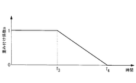
- the position correction unit 152 performs a predetermined period (a period from time T 3 in FIG. 15) to the time when the reference detection position P1 is detected by the GPS 111 (hereinafter referred to as “correction start time”).
- the weighting factor a is 1, then weighted in a predetermined period (period T 4 from the time T 3 in FIG. 15) the coefficient a has a function that decreases to zero at a constant rate.
- the position correction unit 152 uses this function to acquire the weighting coefficient a corresponding to the elapsed time from the correction start time, and corrects the offset vector Vt by multiplying the offset vector Vt by the acquired weighting coefficient a. Then, the position information of the moving object is corrected by adding the corrected offset vector to the position information of the moving object acquired by the position information acquiring unit 11. Thereby, as shown in FIG. 14, the position information after correction becomes a value closer to the position information of the moving body acquired by the position information acquisition unit 11 as the distance from the vicinity of the intersection increases.
- the output unit 16 outputs the corrected position information to the map matching unit 30 when the position is corrected by the correction unit 15, and from the position information acquisition unit 11 when the position is not corrected by the correction unit 15.
- the output position information is output to the map matching unit 30.
- the position information from the correction unit 15 is output from the output unit 16 until the weighting coefficient a becomes zero, and the moving object output from the position information acquisition unit 11 after the weighting coefficient a becomes zero. Is output from the output unit 16.
- the map matching unit 30 includes map information in which a road is composed of a plurality of links, each of which is assigned unique identification information (link ID), and uses the position information of the moving object output from the positioning unit 10. To identify the link closest to the current position of the moving object.
- link ID unique identification information
- a road is divided into a plurality of links in a pseudo manner, and link IDs and position information (for example, latitude and longitude) that are identification information unique to the divided links are associated with each other.
- Map information In the map information, nodes (see black circles in the figure) are set at road intersections and branch points, and basically, line segments between nodes are defined as links. Further, the links set in this way may be further divided into a plurality of nodes. In FIG. 2, 44885, 43492, 31847, and the like indicate link IDs.
- the map matching unit 30 specifies the current position of the moving object on the road by specifying the link ID corresponding to the position information of the moving object output from the positioning unit 10 from the map information.
- the charging processing unit 40 has a database (not shown) in which a link ID in which a position related to charging is set is registered, and when the link ID registered in the database is input from the map matching unit 30. , Processing related to billing. As an example of processing related to charging, there are processing for notifying the driver of charging start and confirmation of collection fee, charging start processing, collection fee determination processing, and the like.
- the position information acquisition unit 11 the position information of the moving body is sequentially acquired from the above equation (1) using the detection position of the GPS 111 and the detection position of the dead reckoning unit 112.
- the data are output to the acquisition unit 14, the correction unit 15, and the output unit 16, respectively.
- Whether the detector 13 has entered one of the intersection areas R based on the intersection area R registered in the intersection information stored in the intersection information storage section 12 and the position information from the position information acquisition section 11. Determine whether or not.
- it is determined that the vehicle has entered one of the intersection areas R it is determined whether or not the vehicle has bent at the intersection.
- the angle ⁇ (hereinafter referred to as “bending angle ⁇ ”) between the traveling direction before the first predetermined time T 1 [second] and the current traveling direction in the intersection region R. .) Is detected as the reference detection position when the first predetermined angle ⁇ 1 [deg] is reached.
- the determination and the detection method of the reference detection position are as described above.
- the detection unit 13 notifies the intersection position acquisition unit 14 of the approach direction when the vehicle enters the intersection region R and the direction of change in the intersection region R, and outputs the reference detection position to the correction unit 15.
- the intersection position acquisition unit 14 stores the coordinates of the corresponding intersection position in the intersection information storage unit 12 based on the approach direction to the intersection region R of the moving body notified from the detection unit 13 and the direction of the change in the intersection region R.
- the coordinates of the intersection position are output to the correction unit 15.
- the correction amount calculation unit 151 of the correction unit 15 calculates an offset vector Vt that matches the position coordinates of the intersection position acquired by the intersection position acquisition unit 14 with the reference detection position detected by the detection unit 13 (see FIG. 14). ), And outputs the offset vector Vt to the position correction unit 152.
- the position correction unit 152 corrects the position information of the moving object by adding the offset vector Vt multiplied by the weighting coefficient a obtained from the function shown in FIG. 15 to the position information of the moving object from the position information acquiring unit 11. Then, the corrected position information is output to the output unit 16.
- the output unit 16 outputs the corrected position information to the map matching unit 30 during the period in which the corrected position information is input from the correction unit 15. Further, for the period when the corrected position information is not input from the correction unit 15, the position information output from the position information acquisition unit 11 is output to the map matching unit 30.
- the map matching unit 30 acquires a link ID corresponding to the position information input from the output unit 16 from the map information, and outputs the link ID to the billing processing unit 40.
- the billing processing unit 40 searches a database (not shown) using the link ID input from the map matching unit 30 as a key, and when the link ID input from the map matching unit 30 is registered in the database, for example, Perform billing process. For example, in the case of a link ID that requires a notification regarding charging, a notification regarding charging is sent to the driver.
- a reference intersection position according to the approach direction to the intersection and the direction of change at the intersection. are registered, and when passing through the intersection, the position information is corrected using the coordinates of the appropriate intersection position based on the approach direction to the intersection and the direction of change of needle.
- the correction accuracy of the position information after passing the intersection compared to the case where the same intersection position is registered regardless of the approach direction and the direction of the course.
- the billing position is set after passing through the intersection, it is possible to quickly detect that the billing position has been passed. As a result, it is possible to immediately inform the driver that the billing position has been passed.
- the position information is corrected by adding the offset vector Vt corresponding to the time to the positioning result of the GPS 111.
- This method is effective when an equivalent offset is always working, but the detection error by the GPS 111 may also change with time.
- the position correction based on the offset vector Vt described above may not necessarily obtain the expected accuracy. Therefore, instead of the above correction method, the following correction method may be adopted.
- the weighting coefficient w is set to zero and switch to position detection by the dead reckoning navigation unit 112 with reference to the position coordinates of the intersection position.
- the position information detected by the dead reckoning navigation unit 112 is not reflected as a result of positioning by the GPS 111, and is output from the position information acquisition unit 11 to the output unit 16 as the position information of the moving body and output to the map matching unit 30.
- the Rukoto In this case, after the weighting coefficient a of the offset vector Vt becomes zero, the weighting coefficient w is determined based on, for example, the calculation formula based on the standard deviation s described above.
- a function for increasing the weighting coefficient w is prepared in advance as shown in FIG.
- the position information of the moving body reflecting many detection results by the dead reckoning navigation unit 112 is output to the output unit 16, and the moving body reflecting many detection results by the GPS 111 as time passes. Is output to the output unit 16.
- the dead reckoning unit 112 is mainly used in the initial correction period in which the detection accuracy by the dead reckoning unit 112 is expected to be higher than that of the GPS 111, and thereafter, the weight of the position detection of the GPS 111 is gradually increased.
- the position is completely switched to the position detection by the GPS 111.
- the positioning result of the GPS 111 may be used for speed detection by the measurement navigation unit 112.
- the integration of an acceleration sensor may be used for the speed.
- the speed detection accuracy gradually deteriorates due to the accumulation of errors as described above. Therefore, for the detection of the speed at which the error is accumulated, the positioning result of the GPS 111 may be used to avoid an increase in error due to integration.
- the link ID existing ahead of the intersection is added to the position information and output. Also good.
- the map matching unit 30 can uniquely identify the link by outputting the link ID of the link that the mobile body that has passed through the intersection enters next. In order to add such a link ID, for example, a link ID existing ahead of the intersection at the intersection may be registered in association with the coordinates of each intersection position.
Landscapes
- Engineering & Computer Science (AREA)
- Radar, Positioning & Navigation (AREA)
- Remote Sensing (AREA)
- Physics & Mathematics (AREA)
- Theoretical Computer Science (AREA)
- General Physics & Mathematics (AREA)
- Educational Administration (AREA)
- Educational Technology (AREA)
- Business, Economics & Management (AREA)
- Mathematical Physics (AREA)
- Automation & Control Theory (AREA)
- Navigation (AREA)
- Instructional Devices (AREA)
Abstract
本発明の目的は、交差点通過後における位置検出精度を向上させることである。車載装置1の測位部(10)は、交差点への進入方位及び変針方向の組み合わせに関連付けて交差点位置の座標が登録されている交差点情報を記憶する交差点情報記憶部(12)を有し、各交差点に設定された交差点領域内において、所定の条件を満たしたときの移動体の位置を基準検出位置として検出するとともに交差点領域への進入方位及び変針方向に基づいて、該当する交差点位置の座標を取得し、該交差点位置の位置座標と該基準検出位置とを用いて位置情報取得部(11)によって取得された移動体の位置情報を補正する。
Description
本発明は、車載装置及びその位置補正方法に関するものである。
従来、カーナビゲーションシステムなどの機能の一つとして、GPSなどを用いて取得した位置情報と、予め用意された地図情報とを用いて移動経路を特定する、いわゆるマップマッチングといわれる技術が知られている(例えば、特許文献1参照)。
このマップマッチングは、道路課金(ロードプライシング)にも利用されており、例えば、所定の課金位置を通過したことをマップマッチングで検出し、課金処理を行っている。
このマップマッチングは、道路課金(ロードプライシング)にも利用されており、例えば、所定の課金位置を通過したことをマップマッチングで検出し、課金処理を行っている。
近年、道路課金においては、所定の課金位置を通過した場合に、即時的にそのことを運転手に通知することが要請されている。
しかしながら、従来のマップマッチングでは、GPSの位置検出誤差により、地図上における走行位置と実際の走行位置とに誤差が生じており、所定の課金位置を通過したことを瞬時に認識することが難しく、課金位置を通過したことを運転手に即時的に通知することが困難な場合があった。
しかしながら、従来のマップマッチングでは、GPSの位置検出誤差により、地図上における走行位置と実際の走行位置とに誤差が生じており、所定の課金位置を通過したことを瞬時に認識することが難しく、課金位置を通過したことを運転手に即時的に通知することが困難な場合があった。
本発明の目的は、交差点通過後における位置検出精度を向上させることである。
本発明の第1態様は、移動体の位置情報を取得する位置情報取得手段と、少なくとも1つの交差点について、該交差点への進入方位及び変針方向の組み合わせに関連付けて交差点位置の座標が登録されている交差点情報を記憶する交差点情報記憶手段と、各前記交差点に設定された交差点領域内において、予め設定された第1所定時間前の進行方向と現在の進行方向とのなす角が第1所定角度に達したときの前記移動体の位置を基準検出位置として検出する検出手段と、前記移動体の前記交差点領域への進入方位及び該交差点領域における変針方向に基づいて、該当する交差点位置の座標を前記交差点情報から取得する交差点位置取得手段と、前記交差点位置取得手段によって取得された交差点位置の位置座標と、前記検出手段によって検出された基準検出位置とを用いて、前記位置情報取得手段によって取得された移動体の位置情報を補正する補正手段とを具備する車載装置である。
本態様によれば、各交差点において、その交差点への進入方位やその交差点における変針方向に応じて、基準となる交差点位置の座標を登録しておき、交差点を通過する際には、その交差点への進入方位、変針方向に基づいて適切な交差点位置の座標を用いて位置情報を補正する。これにより、例えば、進入方位や変針方向にかかわらず、同一の交差点位置が登録されている場合に比べて、交差点通過後における位置情報の補正精度を向上させることが可能となる。この結果、例えば、交差点を通過した後に課金位置が設定されていた場合には、その課金位置を通過したことを速やかに検知することができ、課金位置を通過したことを即自的に運転手に伝えることが可能となる。
上記車載装置において、前記検出手段は、前記第1所定時間よりも長い第2所定時間前の進行方向と現在の進行方向とがなす角が、前記第1所定角度よりも大きな第2所定角度に達した場合に、該第2所定時間前から現在までの走行軌跡に基づいて、前記第2所定時間前の進行方向に対して前記第1所定角度となる前記移動体の位置を基準位置として検出してもよい。
このようにすることで、交差点において移動体が曲がったことを確実に検知することができ、その一方で、交差点を蛇行して直進した場合などを排除することが可能となる。
上記車載装置は、角速度センサを有し、前記検出手段は、前記角速度センサの計測値の積分値を用いて走行角度を検出することとしてもよい。
角速度センサを用いて走行角度を検出することで、所望の精度を保ちながら容易に走行角度を検出することが可能となる。
上記車載装置において、前記補正手段は、前記交差点位置取得手段によって取得された交差点位置の座標に、前記検出手段によって検出された基準検出位置を一致させるオフセットベクトルを算出する補正量算出手段と、前記オフセットベクトルを用いて前記位置情報取得手段によって取得された前記移動体の位置情報を補正する位置補正手段とを備えることとしてもよい。
オフセットベクトルを用いて位置情報を補正するので、位置情報取得手段によって取得された位置情報に一様のオフセットがのっている場合に、このオフセット誤差を有効に除去することができる。
上記車載装置において、前記位置補正手段は、前記オフセットベクトルに時間に応じてゼロまで漸減する重み付け係数を乗じることにより、前記オフセットベクトルを補正し、補正後のオフセットベクトルを前記位置情報取得手段によって取得された前記移動体の位置情報に足しこむことで、前記移動体の位置情報を補正することとしてもよい。
オフセットベクトルをゼロまで漸減させるので、徐々に位置情報取得手段による位置情報検出に移行させることが可能となる。
上記車載装置において、前記位置情報取得手段は、GPSと、推測航法手段とを備え、前記補正手段は、前記基準検出位置を前記交差点位置の位置座標と一致させる補正を行い、前記位置情報取得手段は、前記補正手段による前記基準検出位置の補正がなされた場合に、前記移動体の位置情報として前記交差点位置を基準とした前記推測航法手段による検出位置を採用し、その後、前記GPSによる検出位置の採用に切り替えることとしてもよい。
GPSと推測航法手段とを用いるとともに、推測航法手段による検出結果の方が精度が得られる時期において推測航法手段を用い、また、推測航法手段による位置検出に誤差が多く含まれる時期についてはGPSに切り替えるので、時期に応じて最適な位置検出手段を用いて位置検出を行うことができる。これにより、位置情報の検出精度を向上させることが可能となる。
上記車載装置において、前記位置情報取得手段は、前記位置情報取得手段は、GPSと推測航法手段とを備え、前記推測航法手段による位置情報と前記GPSによる位置情報とを加重平均することで前記移動体の位置情報を取得し、前記補正手段による前記基準検出位置の補正がなされた場合に、補正直後においては推定航法手段の重み付けを大きくし、時間経過につれて、前記GPSの重みを漸増させることとしてもよい。
これにより、時期に応じて最適な位置検出手段を用いて位置検出を行うことができるとともに、推定航法手段からGPSによる位置検出へと徐々にシフトさせることが可能となる。これにより、検出位置の連続性を保つことができる。
上記車載装置において、前記推測航法手段による位置情報の取得において、速度情報に関しては前記GPSによって取得される情報を利用することとしてもよい。
このようにすることで、誤差が積算されるという推定航法手段の欠点を解消することが可能となる。
上記車載装置は、前記位置情報取得手段によって取得された移動体の位置情報を出力するとともに、前記補正手段によって前記移動体の位置情報が補正されている期間は、補正後の前記移動体の位置情報を出力する出力手段と、道路が複数のリンクで構成され、各リンクに固有の識別情報と位置情報とが割り当てられた地図情報を有し、前記出力手段から出力される前記移動体の位置情報を用いて、地図上における移動体の位置を特定するマップマッチング手段とを更に備えることとしてもよい。
このような構成によれば、マップマッチングの精度を向上させることが可能となる。
上記車載装置においては、前記交差点情報において、各前記交差点位置の座標には、該交差点を曲がった先に存在するリンクの識別情報が登録されており、前記出力手段は、前記移動体の位置情報に前記リンクの識別情報を付加して出力することとしてもよい。
このように、交差点を通過した移動体が次に進入するリンクのリンクIDを出力することにより、マップマッチング手段では一意的にリンクを特定することが可能となる。
本発明の第2態様は、少なくとも1つの交差点について、該交差点への進入方位及び変針方向の組み合わせに関連付けて交差点位置の座標が登録されている交差点情報を予め用意しておき、移動体の位置情報を取得する位置情報取得過程と、各前記交差点に設定された交差点領域内において、予め設定された第1所定時間前の進行方向と現在の進行方向とのなす角が第1所定角度に達したときの前記移動体の位置を基準検出位置として検出する検出過程と、前記移動体の前記交差点領域への進入方位及び該交差点領域における変針方向に基づいて、該当する交差点位置の座標を前記交差点情報から取得する交差点位置取得過程と、前記交差点位置取得過程において取得された交差点位置の位置座標と、前記検出過程において検出された基準検出位置とを用いて、前記位置情報取得過程において取得された移動体の位置情報を補正する補正過程とを具備する車載装置の位置補正方法である。
本発明の第3態様は、少なくとも1つの交差点について、該交差点への進入方位及び変針方向の組み合わせに関連付けて交差点位置の座標が登録されている交差点情報が予め記憶されており、移動体の位置情報を取得する位置情報取得処理と、各前記交差点に設定された交差点領域内において、予め設定された第1所定時間前の進行方向と現在の進行方向とのなす角が第1所定角度に達したときの前記移動体の位置を基準検出位置として検出する検出処理と、前記移動体の前記交差点領域への進入方位及び該交差点領域における変針方向に基づいて、該当する交差点位置の座標を前記交差点情報から取得する交差点位置取得処理と、前記交差点位置取得処理において取得された交差点位置の位置座標と、前記検出処理において検出された基準検出位置とを用いて、前記位置情報取得処理において取得された移動体の位置情報を補正する補正処理とをコンピュータに実行させるための車載装置の位置補正プログラムである。
本発明によれば、交差点通過後に課金位置が設置されていた場合に、課金位置の通過通知に関する時間遅れを短くすることができるという効果を奏する。
以下に、本発明に係る車載装置及びその位置補正方法の一実施形態について、図面を参照して説明する。
本実施形態に係る車載装置は、道路課金に広く使用されるものであり、例えば、一例として、課金道路を通過したときに一律の料金が課金されるような課金体系、所定の課金エリア内における走行距離に応じた料金が課金されるような課金体系などに適用される。また、課金エリアあるいは課金道路に進入したときに徴収料金の確定または課金がなされる場合、課金エリアあるいは課金道路から退出したときに徴収料金の確定または課金がなされる場合のいずれの場合にも適用することが可能である。
本実施形態に係る車載装置は、道路課金に広く使用されるものであり、例えば、一例として、課金道路を通過したときに一律の料金が課金されるような課金体系、所定の課金エリア内における走行距離に応じた料金が課金されるような課金体系などに適用される。また、課金エリアあるいは課金道路に進入したときに徴収料金の確定または課金がなされる場合、課金エリアあるいは課金道路から退出したときに徴収料金の確定または課金がなされる場合のいずれの場合にも適用することが可能である。
図1は、本発明の一実施形態に係る車載装置1の機能ブロック図を示した図である。車載装置1は、例えば、コンピュータを搭載しており、以下に示す各部の機能は、その機能に対応するハードウェアや、コンピュータ読み取り可能な記録媒体に記録されたプログラム(位置補正プログラム等)を演算処理装置が実行することにより実現される。
図1に示すように、車載装置1は、移動体の位置情報を出力する測位部10と、マップマッチング部30と、課金処理部40とを備えている。
図1に示すように、車載装置1は、移動体の位置情報を出力する測位部10と、マップマッチング部30と、課金処理部40とを備えている。
測位部10は、位置情報取得部11と、交差点情報記憶部12と、検出部13と、交差点位置取得部14と、補正部15と、出力部16とを主な構成として備えている。
位置情報取得部11は、移動体の位置情報を取得する。位置情報取得部11は、GPS111と、推測航法部112とを備えている。推測航法部112は、車載センサの計測値を用いて移動体の進行方向と移動距離を特定し、現在位置を検出するものである。車載センサの一例としては、ジャイロ、加速度センサ、速度センサ等が挙げられる。
位置情報取得部11は、移動体の位置情報を取得する。位置情報取得部11は、GPS111と、推測航法部112とを備えている。推測航法部112は、車載センサの計測値を用いて移動体の進行方向と移動距離を特定し、現在位置を検出するものである。車載センサの一例としては、ジャイロ、加速度センサ、速度センサ等が挙げられる。
位置情報取得部11は、例えば、GPS111が出力する位置と、推測航法部112が出力する位置とを統合処理(例えば、加重平均)することにより、移動体の位置情報を取得する。例えば、以下の(1)式を用いて移動体の位置情報を取得する。
移動体の位置情報=w×GPSの出力位置+(1-w)×推測航法部の出力位置(1)
(1)式において、wは0以上1.0以下の範囲で動的に変化する重み付け係数である。例えば、GPS111による位置取得が可能な場所では重み付け係数wの値が比較的大きな値に設定され、GPS111による位置取得が不可能または困難な場所、例えば、トンネル内、高層ビル群の間などにおいては、重み付け係数wはゼロまたはゼロに近い値に設定される。より具体的には、GPS111からは、ある時刻の測位位置とともにその誤差の標準偏差sが出力される。この標準偏差sは、GPS111の受信状態がよい場所では比較的小さい値をとり、受信状態の悪い場所では比較的大きな値をとる。そして、例えば、位置情報取得部11は、この標準偏差sをパラメータとして含む重み付け係数wの算出式(例えば、w=1/s)を予め保有しており、この算出式にGPS111から出力された標準偏差sを代入することにより、重み付け係数wを算出する。なお、上述したように、wの値は0以上1.0以下の範囲に制限される。
交差点情報記憶部12は、少なくとも1つの交差点について、該交差点への進入方位及び変針方向の組み合わせ毎に、それぞれ異なる交差点位置の座標(緯度経度)が登録されている交差点情報を記憶する。また、各交差点には後述する交差点領域R(図4参照)が設定されており、この交差点領域Rの情報も交差点情報に含まれているものとする。
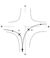
例えば、図3に示すように、幅が広い交差点などでは、その交差点への進入方位、及び、交差点における変針方向(右折、左折など)に応じて、交差点を曲がる際の走行軌跡が異なることが多く、交差点の基準位置を進入方位及び変針方向に応じて設定することが好ましい。これは、進入方位及び変針方向にかかわらず一様に交差点の基準位置(例えば、交差点の中心など)を設定してしまうと、交差点における位置情報の補正精度を低下させる可能性が高いからである。
本実施形態においては、例えば、図3に示すように、進入方位が南、変針方向が左折の場合には交差点位置Aの座標が、進入方位が南、変針方向が右折の場合には交差点位置Bの座標が一例として登録されている。
また、交差点位置の座標に関連付けられる進入方位および変針方向は、ある程度の幅をもって設定されることが好ましい。これは、道路幅が広ければ進入方位は移動体によって異なることが考えられる上、GPS111や推測航法部112による位置検出や方位検出にも誤差が含まれているからである。
また、交差点位置の座標に関連付けられる進入方位および変針方向は、ある程度の幅をもって設定されることが好ましい。これは、道路幅が広ければ進入方位は移動体によって異なることが考えられる上、GPS111や推測航法部112による位置検出や方位検出にも誤差が含まれているからである。
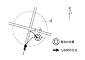
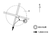
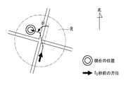
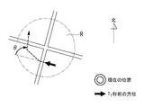
検出部13は、図4に示すように、各交差点に設定された交差点領域R内において、第1所定時間T1[秒]前の進行方向と現在の進行方向とのなす角θ(以下「曲がり角度θ」という。)が第1所定角度θ1[deg]に達したときに、移動体が交差点を曲がったと判定し、そのときの移動体の位置を基準検出位置として検出する。
ここで、第1所定時間T1[秒]、第1所定角度θ1は、任意に設定可能な値であり、第1所定時間T1[秒]は、例えば、5[秒]から20[秒]の間に設定され、第1所定角度θ1は、40[deg]から65[deg]の間に設定される。もちろん、場合に応じてこれらの範囲外に設定することも可能である。
一例として、第1所定時間T1[秒]は15[秒]、第1所定角度θ1は45「deg」に設定される。
ここで、第1所定時間T1[秒]、第1所定角度θ1は、任意に設定可能な値であり、第1所定時間T1[秒]は、例えば、5[秒]から20[秒]の間に設定され、第1所定角度θ1は、40[deg]から65[deg]の間に設定される。もちろん、場合に応じてこれらの範囲外に設定することも可能である。
一例として、第1所定時間T1[秒]は15[秒]、第1所定角度θ1は45「deg」に設定される。
或いは、検出部13は、各交差点に設定された交差点領域R内において、第1所定時間T1[秒]よりも前である第2所定時間T2[秒]前の進行方向と現在の進行方向とのなす角θが第1所定角度θ1[deg]よりも大きな第2所定角度θ2[deg]に達した時に移動体が交差点を曲がったと判定し、現在から第2所定時間T2[秒]前までの走行軌跡に基づいて、曲がり角度θが第1所定角度θ1[deg]に達した時の移動体の位置を基準検出位置として検出することとしてもよい。
ここで、第2所定時間T2[秒]、第2所定角度θ2は、任意に設定可能な値であり、第2所定時間T2[秒]は、例えば、25[秒]から35[秒]の間に設定され、第2所定角度θ2は、80[deg]から95[deg]の間に設定される。もちろん、場合に応じてこれらの範囲外に設定することも可能である。
交差点領域Rは、図5に示すように、例えば、交差点の中心地Oを中心として半径x[m]程度に設定されている。ここで、半径x[m]は、任意に設定される値である。なお、この交差点領域Rは、隣接する交差点領域が互いに重ならないように設定されることが好ましいが、重なっている場合には、近い方の交差点を曲がったと判断する。
検出部13による交差点曲がり検出及び上記基準検出位置の検出方法の具体例としては、以下の手法が挙げられる。
〔手法1〕
例えば、検出部13は、移動体に設けられた角速度センサの積分値をモニタしており、第1所定時間T1[秒]前から現在までの角速度センサの積分値が、第1所定角度θ1に相当する値に達したときに交差点を曲がったと判定し、そのときの移動体の位置を基準検出位置として検出する。
〔手法1〕
例えば、検出部13は、移動体に設けられた角速度センサの積分値をモニタしており、第1所定時間T1[秒]前から現在までの角速度センサの積分値が、第1所定角度θ1に相当する値に達したときに交差点を曲がったと判定し、そのときの移動体の位置を基準検出位置として検出する。
〔手法2〕
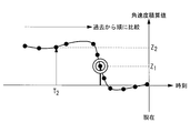
検出部13は、図6に示すように、第1所定時間T1[秒]よりも長い第2所定時間T2[秒]前から現在までの角速度センサの積分値をモニタしており、第2所定時間T2[秒]前からの角速度積算値が、第1所定角度θ1よりも大きな第2所定角度θ2に相当する値Z2に達したことを検出した場合に交差点を曲がったと判定する。そして、検出部13は、第2所定時間T2[秒]前から現在までの角速度積算値の軌跡に基づいて、角速度積分値が第1所定角度θ1に相当する値Z1に達したときの移動体の位置(図6において二重丸で示した時刻における移動体の位置)を基準検出位置として検出する。
検出部13は、図6に示すように、第1所定時間T1[秒]よりも長い第2所定時間T2[秒]前から現在までの角速度センサの積分値をモニタしており、第2所定時間T2[秒]前からの角速度積算値が、第1所定角度θ1よりも大きな第2所定角度θ2に相当する値Z2に達したことを検出した場合に交差点を曲がったと判定する。そして、検出部13は、第2所定時間T2[秒]前から現在までの角速度積算値の軌跡に基づいて、角速度積分値が第1所定角度θ1に相当する値Z1に達したときの移動体の位置(図6において二重丸で示した時刻における移動体の位置)を基準検出位置として検出する。
図6、図7は、第1所定時間T1[秒]を15[秒]、第1所定角度θ1を45「deg」、第2所定時間T2[秒]を30[秒]、第2所定角度θ2を90「deg」に設定した場合の一例を示しており、図6は、右折の場合の角速度積算値Zの軌跡であり、図7は、左折の場合の角速度積算値Zの軌跡である。積算値の正負を区別することにより、右折と左折とを区別することが可能となる。
第2所定角度θ2は、交差点を曲がったと判断するのに十分な角度(例えば、90[deg]等)に設定されることが好ましい。すなわち、上記手法1では、例えば、交差点に停車中の車を避けるために走行方位を大きく変更し、蛇行しながら交差点を直進した場合等についても交差点を曲がったと誤認識してしまう可能性がある。これに対し、手法2によれば、曲がり角度θが、第2所定角度θ2に達したことを検知したときに交差点を曲がったと判定するので、蛇行しながら交差点を直進した場合を排除することが可能となる。
〔手法3〕
検出部13は、例えば、ジャイロの計測結果、GPSの測位結果、右側車輪と左側車輪との回転数の差、ハンドル操作角度などに基づいて曲がり角度θを検出し、曲がり角度θが第1所定角度θ1または第2所定角度θ2に達した時に交差点を曲がったと判定する。
また、この場合の基準検出位置の検出については、図8に示すように、交差点領域Rに進入した時からの角速度センサの計測値をモニタしており、角速度センサの計測値がピーク値を示した時刻の移動体の位置を基準検出位置として検出する。図8は、右折の場合の角速度の軌跡であり、図9は、左折の場合の角速度の軌跡を示している。角速度の正負を区別することにより、右折と左折とを区別することが可能となる。
検出部13は、例えば、ジャイロの計測結果、GPSの測位結果、右側車輪と左側車輪との回転数の差、ハンドル操作角度などに基づいて曲がり角度θを検出し、曲がり角度θが第1所定角度θ1または第2所定角度θ2に達した時に交差点を曲がったと判定する。
また、この場合の基準検出位置の検出については、図8に示すように、交差点領域Rに進入した時からの角速度センサの計測値をモニタしており、角速度センサの計測値がピーク値を示した時刻の移動体の位置を基準検出位置として検出する。図8は、右折の場合の角速度の軌跡であり、図9は、左折の場合の角速度の軌跡を示している。角速度の正負を区別することにより、右折と左折とを区別することが可能となる。
交差点位置取得部14は、移動体の交差点領域Rへの進入方位及び該交差点領域における変針方向に基づいて、該当する交差点位置の座標を交差点情報記憶部14に記憶されている交差点情報から取得する。
例えば、図10、図11に示すように、南の方位から交差点に進入し、右折した場合には、交差点位置取得部14は、進入方位として南の方位が登録されており、かつ、交差点領域における変針方向が右折に設定されている交差点位置の座標を交差点情報から取得する。なお、図10において走行軌跡が道路上にないのはGPSによる測位誤差が大きいことを示している。
例えば、図10、図11に示すように、南の方位から交差点に進入し、右折した場合には、交差点位置取得部14は、進入方位として南の方位が登録されており、かつ、交差点領域における変針方向が右折に設定されている交差点位置の座標を交差点情報から取得する。なお、図10において走行軌跡が道路上にないのはGPSによる測位誤差が大きいことを示している。
また、図12に示すように、南の方位から交差点に進入し、左折した場合には、交差点位置取得部14は、進入方位として南の方位が登録されており、かつ、交差点領域における変針方向が左折に設定されている交差点位置の座標を交差点情報から取得する。
また、図13に示すように、東の方位から交差点に進入し、右折した場合には、交差点位置取得部14は、進入方位として東の方位が登録されており、かつ、交差点領域における変針方向が右折に設定されている交差点位置の座標を交差点情報から取得する。
このように、交差点領域に進入した方位及び交差点領域内における変針方位に応じてそれぞれ異なる交差点位置の座標が交差点情報から取得されることとなる。
また、図13に示すように、東の方位から交差点に進入し、右折した場合には、交差点位置取得部14は、進入方位として東の方位が登録されており、かつ、交差点領域における変針方向が右折に設定されている交差点位置の座標を交差点情報から取得する。
このように、交差点領域に進入した方位及び交差点領域内における変針方位に応じてそれぞれ異なる交差点位置の座標が交差点情報から取得されることとなる。
補正部15は、交差点位置取得部14によって取得された交差点位置の位置座標と、検出部13によって検出された基準検出位置とを用いて、位置情報取得部11から出力される移動体の位置情報を補正する。
具体的には、補正部15は、補正量算出部151と、位置補正部152とを備えている。補正量算出部151は、図14に示すように、交差点位置取得部14によって取得された交差点位置の座標P0に、検出部13によって検出された基準検出位置P1を一致させるオフセットベクトルVtを算出する。
位置補正部152は、オフセットベクトルVtを用いて位置情報取得部11によって取得された移動体の位置情報を補正する。例えば、位置補正部152は、位置情報取得部11によって取得された移動体の位置情報に、オフセットベクトルVtを足しこむことで位置情報を補正する。
具体的には、補正部15は、補正量算出部151と、位置補正部152とを備えている。補正量算出部151は、図14に示すように、交差点位置取得部14によって取得された交差点位置の座標P0に、検出部13によって検出された基準検出位置P1を一致させるオフセットベクトルVtを算出する。
位置補正部152は、オフセットベクトルVtを用いて位置情報取得部11によって取得された移動体の位置情報を補正する。例えば、位置補正部152は、位置情報取得部11によって取得された移動体の位置情報に、オフセットベクトルVtを足しこむことで位置情報を補正する。
より具体的には、補正量算出部151によって基準検出位置P1を交差点位置の座標P0に一致させるようなオフセットベクトルVtが算出されると、位置補正部152は、オフセットベクトルVtに、時間に応じてゼロまで漸減する重み付け係数aを乗じることにより、オフセットベクトルVtを補正する。
例えば、位置補正部152は、図15に示すように、基準検出位置P1がGPS111によって検出された時刻(以下「補正開始時刻」という。)から所定の期間(図15において時刻T3までの期間)においては重み付け係数aが1であり、その後、所定の期間(図15における時刻T3からT4の期間)において重み付け係数aが一定の割合でゼロまで減少する関数を有している。
例えば、位置補正部152は、図15に示すように、基準検出位置P1がGPS111によって検出された時刻(以下「補正開始時刻」という。)から所定の期間(図15において時刻T3までの期間)においては重み付け係数aが1であり、その後、所定の期間(図15における時刻T3からT4の期間)において重み付け係数aが一定の割合でゼロまで減少する関数を有している。
位置補正部152は、この関数を用いて補正開始時刻からの経過時間に対応する重み付け係数aを取得し、取得した重み付け係数aをオフセットベクトルVtに乗じることで、オフセットベクトルVtを補正する。そして、補正後のオフセットベクトルを位置情報取得部11によって取得された移動体の位置情報に足しこむことで、移動体の位置情報を補正する。
これにより、図14に示すように、交差点付近から遠ざかるにつれて、補正後の位置情報は位置情報取得部11によって取得される移動体の位置情報に近い値となる。
これにより、図14に示すように、交差点付近から遠ざかるにつれて、補正後の位置情報は位置情報取得部11によって取得される移動体の位置情報に近い値となる。
出力部16は、補正部15によって位置補正がされている場合には補正後の位置情報をマップマッチング部30に出力し、補正部15によって補正されていない場合には、位置情報取得部11から出力された位置情報をマップマッチング部30に出力する。これにより、重み付け係数aがゼロになるまでは、補正部15からの位置情報が出力部16から出力され、重み付け係数aがゼロになった後は、位置情報取得部11から出力される移動体の位置情報が出力部16から出力されることとなる。
マップマッチング部30は、道路が複数のリンクで構成され、各リンクに固有の識別情報(リンクID)が割り当てられた地図情報を有し、測位部10から出力される移動体の位置情報を用いて、現在の移動体の位置に最も近いリンクを特定する。
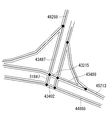
例えば、地図情報は、図2に示すように、道路が複数のリンクに疑似的に分割され、分割されたリンクに固有の識別情報であるリンクID及び位置情報(例えば、緯度経度)が対応付けられた地図情報である。地図情報において、道路の交差点及び分岐点にはノード(図中の黒丸参照)が設定され、基本的には、ノード間における線分がリンクとして定義されている。また、このようにして設定されたリンクを更に細かく分断し、ノード間を複数のリンクで構成するようにしてもよい。図2において、44885、43492、31847等は、各リンクIDを示している。
マップマッチング部30は、測位部10から出力される移動体の位置情報に対応するリンクIDを地図情報から特定することにより、道路上における移動体の現在位置を特定する。
マップマッチング部30は、測位部10から出力される移動体の位置情報に対応するリンクIDを地図情報から特定することにより、道路上における移動体の現在位置を特定する。
課金処理部40は、課金に関する位置が設定されているリンクIDが登録されたデータベース(図示略)を有しており、データベースに登録されているリンクIDがマップマッチング部30から入力された場合に、課金に関する処理を行う。課金に関する処理の一例としては、課金開始や徴収料金の確定を運転手に通知する処理や、課金開始処理、徴収料金の確定処理などが挙げられる。
次に、本実施形態に係る車載装置1の動作について説明する。
まず、位置情報取得部11において、GPS111の検出位置及び推測航法部112の検出位置を用いて上記(1)式から移動体の位置情報が逐次取得され、その位置情報が検出部13、交差点位置取得部14、補正部15、出力部16にそれぞれ出力される。
検出部13は、交差点情報記憶部12に格納されている交差点情報に登録されている交差点領域Rと位置情報取得部11からの位置情報とに基づいて、いずれかの交差点領域Rに進入したか否かを判定する。この結果、いずれかの交差点領域Rに進入したと判定した場合には、その交差点において曲がったか否かを判定する。そして、交差点を曲がったと判定した場合には、当該交差点領域R内において、第1所定時間T1[秒]前の進行方向と現在の進行方向とのなす角θ(以下「曲がり角度θ」という。)が第1所定角度θ1[deg]に達したときの移動体の位置を基準検出位置として検出する。
なお、上記判定及び基準検出位置の検出方法については、上述した通りである。
検出部13は、交差点領域Rに進入した時の進入方位及び交差点領域Rにおける変針方向を交差点位置取得部14に通知するとともに、基準検出位置を補正部15に出力する。
まず、位置情報取得部11において、GPS111の検出位置及び推測航法部112の検出位置を用いて上記(1)式から移動体の位置情報が逐次取得され、その位置情報が検出部13、交差点位置取得部14、補正部15、出力部16にそれぞれ出力される。
検出部13は、交差点情報記憶部12に格納されている交差点情報に登録されている交差点領域Rと位置情報取得部11からの位置情報とに基づいて、いずれかの交差点領域Rに進入したか否かを判定する。この結果、いずれかの交差点領域Rに進入したと判定した場合には、その交差点において曲がったか否かを判定する。そして、交差点を曲がったと判定した場合には、当該交差点領域R内において、第1所定時間T1[秒]前の進行方向と現在の進行方向とのなす角θ(以下「曲がり角度θ」という。)が第1所定角度θ1[deg]に達したときの移動体の位置を基準検出位置として検出する。
なお、上記判定及び基準検出位置の検出方法については、上述した通りである。
検出部13は、交差点領域Rに進入した時の進入方位及び交差点領域Rにおける変針方向を交差点位置取得部14に通知するとともに、基準検出位置を補正部15に出力する。
交差点位置取得部14は、検出部13から通知された移動体の交差点領域Rへの進入方位及び該交差点領域Rにおける変針方向に基づいて、該当する交差点位置の座標を交差点情報記憶部12に記憶されている交差点情報から取得し、交差点位置の座標を補正部15に出力する。
補正部15の補正量算出部151は、交差点位置取得部14によって取得された交差点位置の位置座標に、検出部13によって検出された基準検出位置を一致させるオフセットベクトルVtを算出し(図14参照)、このオフセットベクトルVtを位置補正部152に出力する。
位置補正部152は、図15に示した関数から得られる重み付け係数aを乗じたオフセットベクトルVtを位置情報取得部11からの移動体の位置情報に足しこむことで移動体の位置情報を補正し、補正後の位置情報を出力部16に出力する。
位置補正部152は、図15に示した関数から得られる重み付け係数aを乗じたオフセットベクトルVtを位置情報取得部11からの移動体の位置情報に足しこむことで移動体の位置情報を補正し、補正後の位置情報を出力部16に出力する。
出力部16は、補正部15から補正後の位置情報が入力されている期間については補正後の位置情報をマップマッチング部30に出力する。また、補正後の位置情報が補正部15から入力されていない期間については、位置情報取得部11から出力される位置情報をマップマッチング部30に出力する。
マップマッチング部30は、出力部16から入力された位置情報に該当するリンクIDを地図情報から取得し、そのリンクIDを課金処理部40に出力する。
課金処理部40は、マップマッチング部30から入力されたリンクIDをキーとしてデータベース(図示略)を検索し、マップマッチング部30から入力されたリンクIDがデータベースに登録されていた場合に、例えば、課金処理を行う。例えば、課金に関する通知が必要であるリンクIDであった場合には、運転手に対して課金に関する通知を行う。
課金処理部40は、マップマッチング部30から入力されたリンクIDをキーとしてデータベース(図示略)を検索し、マップマッチング部30から入力されたリンクIDがデータベースに登録されていた場合に、例えば、課金処理を行う。例えば、課金に関する通知が必要であるリンクIDであった場合には、運転手に対して課金に関する通知を行う。
以上、説明してきたように、本実施形態に係る車載装置1及びその位置補正方法によれば、各交差点において、その交差点への進入方位やその交差点における変針方向に応じて、基準となる交差点位置の座標を登録しておき、交差点を通過する際には、その交差点への進入方位、変針方向に基づいて適切な交差点位置の座標を用いて位置情報を補正する。これにより、例えば、進入方位や変針方向にかかわらず、同一の交差点位置が登録されている場合に比べて、交差点通過後における位置情報の補正精度を向上させることが可能となる。これにより、例えば、交差点を通過した後に課金位置が設定されていた場合には、その課金位置を通過したことを速やかに検知することができる。これにより、課金位置を通過したことを即自的に運転手に伝えることが可能となる。
なお、上述した実施形態に係る車載装置1及びその位置補正方法によれば、交差点通過後においては、GPS111の測位結果に対して時間に応じたオフセットベクトルVtを足しこむことにより、位置情報を補正していた。この方法は、常に同等のオフセットが働いているときには有効であるが、GPS111による検出誤差も時間に応じて変化することがある。この場合には、上述したオフセットベクトルVtに基づく位置補正では必ずしも期待する精度が得られないおそれがある。そこで、上記補正方法に代えて、以下のような補正方法をとることとしてもよい。
例えば、図16に示すように、検出部13によって検出された基準検出位置を交差点位置の位置座標と一致させた後においては、移動体の位置情報を算出する際に、上記(1)式における重み付け係数wをゼロに設定し、この交差点位置の位置座標を基準とした推測航法部112による位置検出に切り替えることとしてもよい。これにより、GPS111による測位結果が反映されず、推測航法部112によって検出される位置情報が、移動体の位置情報として位置情報取得部11から出力部16に出力され、マップマッチング部30に出力されることとなる。この場合、オフセットベクトルVtの重み付け係数aがゼロとなった以降は、重み付け係数wは、例えば、上述した標準偏差sに基づく算出式に基づいて決定されることとなる。
また、上記のように推測航法部112による位置情報取得とGPS111による位置情報取得とを完全に切り替えるのではなく、例えば、図17に示すように、重み付け係数wが漸増するような関数を予め用意しておき、この関数を用いて移動体の位置情報を取得することとしてもよい。
これにより、補正開始時刻においては、推測航法部112による検出結果が多く反映された移動体の位置情報が出力部16に出力され、時間が経過するにつれてGPS111による検出結果が多く反映された移動体の位置情報が出力部16に出力されることとなる。
例えば、推測航法部112による位置検出は、センサの計測値を積分して行われることから、最初はそれなりの精度が期待できるが、時間が経過するにつれて誤差が大きくなり、検出精度が悪化するという問題がある。そこで、推測航法部112による検出精度がGPS111よりも高いことが期待される補正初期の期間においては、推測航法部112をメインに使うこととし、その後においては、徐々にGPS111の位置検出の重みを増加させ、最終的にはGPS111による位置検出に完全に切り替えることとする。これにより、時間経過に応じて適切な位置検出手段を採用することができ、位置検出精度を更に向上させることが可能となる。
例えば、推測航法部112による位置検出は、センサの計測値を積分して行われることから、最初はそれなりの精度が期待できるが、時間が経過するにつれて誤差が大きくなり、検出精度が悪化するという問題がある。そこで、推測航法部112による検出精度がGPS111よりも高いことが期待される補正初期の期間においては、推測航法部112をメインに使うこととし、その後においては、徐々にGPS111の位置検出の重みを増加させ、最終的にはGPS111による位置検出に完全に切り替えることとする。これにより、時間経過に応じて適切な位置検出手段を採用することができ、位置検出精度を更に向上させることが可能となる。
また、上記方法の変形例として、図18に示すように、測定航法部112による速度検出にGPS111の測位結果を用いることとしてもよい。例えば、速度については加速度センサの積分が用いられることがあり、このような場合には、上述したような誤差の累積により速度検出精度が徐々に悪化することが懸念される。従って、誤差が累積される速度の検出についてはGPS111の測位結果を用い、積分による誤差の増大を回避することとしてもよい。
また、本実施形態においては、位置情報のみを測位部10からマップマッチング部30に出力することとしたが、当該交差点を曲がった先に存在するリンクIDを位置情報に付加して出力することとしてもよい。このように、交差点を通過した移動体が次に進入するリンクのリンクIDを出力することにより、マップマッチング部30では一意的にリンクを特定することが可能となる。
このようなリンクIDの付加を行うためには、例えば、各交差点位置の座標に関連付けて交差点を曲がった先に存在するリンクIDを登録しておけばよい。
このようなリンクIDの付加を行うためには、例えば、各交差点位置の座標に関連付けて交差点を曲がった先に存在するリンクIDを登録しておけばよい。
以上、本発明の実施形態について図面を参照して詳述してきたが、具体的な構成はこの実施形態に限られるものではなく、本発明の要旨を逸脱しない範囲の設計変更等も含まれる。
1 車載装置
10 測位部
11 位置情報取得部
12 交差点情報記憶部
13 検出部
14 交差点位置取得部
15 補正部
16 出力部
30 マップマッチング部
40 課金処理部
111 GPS
112 推測航法部
151 補正量算出部
152 位置補正部
10 測位部
11 位置情報取得部
12 交差点情報記憶部
13 検出部
14 交差点位置取得部
15 補正部
16 出力部
30 マップマッチング部
40 課金処理部
111 GPS
112 推測航法部
151 補正量算出部
152 位置補正部
Claims (12)
- 移動体の位置情報を取得する位置情報取得手段と、
少なくとも1つの交差点について、該交差点への進入方位及び変針方向の組み合わせに関連付けて交差点位置の座標が登録されている交差点情報を記憶する交差点情報記憶手段と、
各前記交差点に設定された交差点領域内において、予め設定された第1所定時間前の進行方向と現在の進行方向とのなす角が第1所定角度に達したときの前記移動体の位置を基準検出位置として検出する検出手段と、
前記移動体の前記交差点領域への進入方位及び該交差点領域における変針方向に基づいて、該当する交差点位置の座標を前記交差点情報から取得する交差点位置取得手段と、
前記交差点位置取得手段によって取得された交差点位置の位置座標と、前記検出手段によって検出された基準検出位置とを用いて、前記位置情報取得手段によって取得された前記移動体の位置情報を補正する補正手段と
を具備する車載装置。 - 前記検出手段は、前記第1所定時間よりも長い第2所定時間前の進行方向と現在の進行方向とがなす角が、前記第1所定角度よりも大きな第2所定角度に達した場合に、該第2所定時間前から現在までの走行軌跡に基づいて、前記第2所定時間前の進行方向に対して前記第1所定角度となる前記移動体の位置を基準位置として検出する請求項1に記載の車載装置。
- 角速度センサを有し、
前記検出手段は、前記角速度センサの計測値の積分値を用いて走行角度を検出する請求項1または請求項2に記載の車載装置。 - 前記補正手段は、
前記交差点位置取得手段によって取得された交差点位置の座標に、前記検出手段によって検出された基準検出位置を一致させるオフセットベクトルを算出する補正量算出手段と、
前記オフセットベクトルを用いて前記位置情報取得手段によって取得された前記移動体の位置情報を補正する位置補正手段と
を備える請求項1から請求項3のいずれかに記載の車載装置。 - 前記位置補正手段は、前記オフセットベクトルに時間に応じてゼロまで漸減する重み付け係数を乗じることにより、前記オフセットベクトルを補正し、補正後のオフセットベクトルを前記位置情報取得手段によって取得された前記移動体の位置情報に足しこむことで、前記移動体の位置情報を補正する請求項4に記載の車載装置。
- 前記位置情報取得手段は、
GPSと、
推測航法手段と
を備え、
前記補正手段は、前記基準検出位置を前記交差点位置の位置座標と一致させる補正を行い、
前記位置情報取得手段は、前記補正手段による前記基準検出位置の補正がなされた場合に、前記移動体の位置情報として前記交差点位置を基準とした前記推測航法手段による検出位置を採用し、その後、前記GPSによる検出位置の採用に切り替える請求項1から請求項5のいずれかに記載の車載装置。 - 前記位置情報取得手段は、GPSと推測航法手段とを備え、前記推測航法手段による位置情報と前記GPSによる位置情報とを加重平均することで前記移動体の位置情報を取得し、
前記補正手段による前記基準検出位置の補正がなされた場合に、補正直後においては推定航法手段の重み付けを大きくし、時間経過につれて、前記GPSの重みを漸増させる請求項1から請求項5のいずれかに記載の車載装置。 - 前記推測航法手段による位置情報の取得において、速度情報に関しては前記GPSによって取得される情報を利用する請求項6または請求項7に記載の車載装置。
- 前記位置情報取得手段によって取得された移動体の位置情報を出力するとともに、前記補正手段によって前記移動体の位置情報が補正されている期間は、補正後の前記移動体の位置情報を出力する出力手段と、
道路が複数のリンクで構成され、各リンクに固有の識別情報と位置情報とが割り当てられた地図情報を有し、前記出力手段から出力される前記移動体の位置情報を用いて、地図上における移動体の位置を特定するマップマッチング手段と
を備える請求項1から請求項8のいずれかに記載の車載装置。 - 前記交差点情報において、各前記交差点位置の座標には、該交差点を曲がった先に存在するリンクの識別情報が登録されており、
前記出力手段は、前記移動体の位置情報に前記リンクの識別情報を付加して出力する請求項9に記載の車載装置。 - 少なくとも1つの交差点について、該交差点への進入方位及び変針方向の組み合わせに関連付けて交差点位置の座標が登録されている交差点情報を予め用意しておき、
移動体の位置情報を取得する位置情報取得過程と、
各前記交差点に設定された交差点領域内において、予め設定された第1所定時間前の進行方向と現在の進行方向とのなす角が第1所定角度に達したときの前記移動体の位置を基準検出位置として検出する検出過程と、
前記移動体の前記交差点領域への進入方位及び該交差点領域における変針方向に基づいて、該当する交差点位置の座標を前記交差点情報から取得する交差点位置取得過程と、
前記交差点位置取得過程において取得された交差点位置の位置座標と、前記検出過程において検出された基準検出位置とを用いて、前記位置情報取得過程において取得された移動体の位置情報を補正する補正過程と
を具備する車載装置の位置補正方法。 - 少なくとも1つの交差点について、該交差点への進入方位及び変針方向の組み合わせに関連付けて交差点位置の座標が登録されている交差点情報が予め記憶されており、
移動体の位置情報を取得する位置情報取得処理と、
各前記交差点に設定された交差点領域内において、予め設定された第1所定時間前の進行方向と現在の進行方向とのなす角が第1所定角度に達したときの前記移動体の位置を基準検出位置として検出する検出処理と、
前記移動体の前記交差点領域への進入方位及び該交差点領域における変針方向に基づいて、該当する交差点位置の座標を前記交差点情報から取得する交差点位置取得処理と、
前記交差点位置取得処理において取得された交差点位置の位置座標と、前記検出処理において検出された基準検出位置とを用いて、前記位置情報取得処理において取得された移動体の位置情報を補正する補正処理と
をコンピュータに実行させるための車載装置の位置補正プログラム。
Priority Applications (1)
| Application Number | Priority Date | Filing Date | Title |
|---|---|---|---|
| SG11201506700TA SG11201506700TA (en) | 2013-02-25 | 2014-02-21 | Apparatus for vehicle and position correcting method therefor |
Applications Claiming Priority (2)
| Application Number | Priority Date | Filing Date | Title |
|---|---|---|---|
| JP2013034818A JP6173714B2 (ja) | 2013-02-25 | 2013-02-25 | 車載装置及びその位置補正方法並びに位置補正プログラム |
| JP2013-034818 | 2013-02-25 |
Publications (1)
| Publication Number | Publication Date |
|---|---|
| WO2014129602A1 true WO2014129602A1 (ja) | 2014-08-28 |
Family
ID=51391382
Family Applications (1)
| Application Number | Title | Priority Date | Filing Date |
|---|---|---|---|
| PCT/JP2014/054236 Ceased WO2014129602A1 (ja) | 2013-02-25 | 2014-02-21 | 車載装置及びその位置補正方法 |
Country Status (4)
| Country | Link |
|---|---|
| JP (1) | JP6173714B2 (ja) |
| MY (1) | MY174265A (ja) |
| SG (1) | SG11201506700TA (ja) |
| WO (1) | WO2014129602A1 (ja) |
Cited By (1)
| Publication number | Priority date | Publication date | Assignee | Title |
|---|---|---|---|---|
| JP2016176863A (ja) * | 2015-03-20 | 2016-10-06 | カシオ計算機株式会社 | 電子機器、位置補正方法及びプログラム |
Families Citing this family (1)
| Publication number | Priority date | Publication date | Assignee | Title |
|---|---|---|---|---|
| JP6466123B2 (ja) * | 2014-09-26 | 2019-02-06 | シャープ株式会社 | 携帯端末、携帯端末の動作方法、及びプログラム |
Citations (3)
| Publication number | Priority date | Publication date | Assignee | Title |
|---|---|---|---|---|
| JP2008020307A (ja) * | 2006-07-12 | 2008-01-31 | Toyota Motor Corp | ナビゲーション装置、位置検出方法 |
| WO2009008611A2 (en) * | 2007-07-10 | 2009-01-15 | Thinkware Systems Corporation | Map matching method in crossroad and navigation system |
| JP2012022390A (ja) * | 2010-07-12 | 2012-02-02 | Nissan Motor Co Ltd | 右折時走行支援装置、右折時走行支援方法 |
Family Cites Families (2)
| Publication number | Priority date | Publication date | Assignee | Title |
|---|---|---|---|---|
| JP4794384B2 (ja) * | 2006-07-26 | 2011-10-19 | アルパイン株式会社 | 車両位置補正装置及び車両位置補正方法 |
| JP2012127845A (ja) * | 2010-12-16 | 2012-07-05 | Yupiteru Corp | 車載用電子機器及びプログラム |
-
2013
- 2013-02-25 JP JP2013034818A patent/JP6173714B2/ja active Active
-
2014
- 2014-02-21 WO PCT/JP2014/054236 patent/WO2014129602A1/ja not_active Ceased
- 2014-02-21 MY MYPI2015702771A patent/MY174265A/en unknown
- 2014-02-21 SG SG11201506700TA patent/SG11201506700TA/en unknown
Patent Citations (3)
| Publication number | Priority date | Publication date | Assignee | Title |
|---|---|---|---|---|
| JP2008020307A (ja) * | 2006-07-12 | 2008-01-31 | Toyota Motor Corp | ナビゲーション装置、位置検出方法 |
| WO2009008611A2 (en) * | 2007-07-10 | 2009-01-15 | Thinkware Systems Corporation | Map matching method in crossroad and navigation system |
| JP2012022390A (ja) * | 2010-07-12 | 2012-02-02 | Nissan Motor Co Ltd | 右折時走行支援装置、右折時走行支援方法 |
Cited By (1)
| Publication number | Priority date | Publication date | Assignee | Title |
|---|---|---|---|---|
| JP2016176863A (ja) * | 2015-03-20 | 2016-10-06 | カシオ計算機株式会社 | 電子機器、位置補正方法及びプログラム |
Also Published As
| Publication number | Publication date |
|---|---|
| MY174265A (en) | 2020-04-01 |
| JP6173714B2 (ja) | 2017-08-02 |
| SG11201506700TA (en) | 2015-09-29 |
| JP2014163788A (ja) | 2014-09-08 |
Similar Documents
| Publication | Publication Date | Title |
|---|---|---|
| JP5249556B2 (ja) | 走行経路検出用の車載器 | |
| JP6551384B2 (ja) | 車両用注意喚起装置 | |
| JP5472163B2 (ja) | 速度規制値通知装置及び速度規制値通知システム | |
| KR101920303B1 (ko) | 3차원 위치 판정 장치 및 방법 | |
| US11300415B2 (en) | Host vehicle position estimation device | |
| US8140266B2 (en) | Vehicle positioning information updating system | |
| JP4864161B2 (ja) | ナビゲーション装置 | |
| CN105934786B (zh) | 异常行驶部位检测装置以及异常行驶部位检测方法 | |
| JP5422111B2 (ja) | 走行経路検出用の車載器 | |
| JP6451857B2 (ja) | 走行制御装置の制御方法および走行制御装置 | |
| US10289120B2 (en) | Self-position estimation device and self-position estimation method | |
| US20160327400A1 (en) | Host-vehicle-travel-position specification apparatus and host-vehicle-travel-position specification program product | |
| JP4780155B2 (ja) | 車載装置 | |
| JP2015191445A (ja) | 運転支援装置 | |
| US20190265042A1 (en) | Navigation system | |
| JP2019066193A (ja) | 自車位置検出装置 | |
| JP6539129B2 (ja) | 自車位置推定装置、及びそれを用いた操舵制御装置、並びに自車位置推定方法 | |
| JP6717115B2 (ja) | 位置推定装置 | |
| JPH1137776A (ja) | 車両用ナビゲーション装置 | |
| KR20200119092A (ko) | 차량 및 차량의 위치 검출 방법 | |
| JP2018081358A (ja) | 合流支援装置、合流支援システム、車載器及び合流支援方法 | |
| JP6173714B2 (ja) | 車載装置及びその位置補正方法並びに位置補正プログラム | |
| JP2012137361A (ja) | 軌跡情報補正装置、方法およびプログラム | |
| JP6747157B2 (ja) | 自己位置推定方法及び自己位置推定装置 | |
| JP6455292B2 (ja) | 物体検出装置及び物体検出方法 |
Legal Events
| Date | Code | Title | Description |
|---|---|---|---|
| 121 | Ep: the epo has been informed by wipo that ep was designated in this application |
Ref document number: 14754756 Country of ref document: EP Kind code of ref document: A1 |
|
| NENP | Non-entry into the national phase |
Ref country code: DE |
|
| WWE | Wipo information: entry into national phase |
Ref document number: IDP00201505750 Country of ref document: ID |
|
| 122 | Ep: pct application non-entry in european phase |
Ref document number: 14754756 Country of ref document: EP Kind code of ref document: A1 |