WO2014129567A1 - 非接触支持装置及び非接触支持方法 - Google Patents
非接触支持装置及び非接触支持方法 Download PDFInfo
- Publication number
- WO2014129567A1 WO2014129567A1 PCT/JP2014/054096 JP2014054096W WO2014129567A1 WO 2014129567 A1 WO2014129567 A1 WO 2014129567A1 JP 2014054096 W JP2014054096 W JP 2014054096W WO 2014129567 A1 WO2014129567 A1 WO 2014129567A1
- Authority
- WO
- WIPO (PCT)
- Prior art keywords
- suction
- air supply
- preliminary
- levitation
- main
- Prior art date
- Legal status (The legal status is an assumption and is not a legal conclusion. Google has not performed a legal analysis and makes no representation as to the accuracy of the status listed.)
- Ceased
Links
Images






Classifications
-
- H—ELECTRICITY
- H10—SEMICONDUCTOR DEVICES; ELECTRIC SOLID-STATE DEVICES NOT OTHERWISE PROVIDED FOR
- H10P—GENERIC PROCESSES OR APPARATUS FOR THE MANUFACTURE OR TREATMENT OF DEVICES COVERED BY CLASS H10
- H10P72/00—Handling or holding of wafers, substrates or devices during manufacture or treatment thereof
- H10P72/30—Handling or holding of wafers, substrates or devices during manufacture or treatment thereof for conveying, e.g. between different workstations
- H10P72/36—Handling or holding of wafers, substrates or devices during manufacture or treatment thereof for conveying, e.g. between different workstations using air tracks
-
- B—PERFORMING OPERATIONS; TRANSPORTING
- B65—CONVEYING; PACKING; STORING; HANDLING THIN OR FILAMENTARY MATERIAL
- B65G—TRANSPORT OR STORAGE DEVICES, e.g. CONVEYORS FOR LOADING OR TIPPING, SHOP CONVEYOR SYSTEMS OR PNEUMATIC TUBE CONVEYORS
- B65G49/00—Conveying systems characterised by their application for specified purposes not otherwise provided for
- B65G49/05—Conveying systems characterised by their application for specified purposes not otherwise provided for for fragile or damageable materials or articles
- B65G49/06—Conveying systems characterised by their application for specified purposes not otherwise provided for for fragile or damageable materials or articles for fragile sheets, e.g. glass
- B65G49/063—Transporting devices for sheet glass
- B65G49/066—Transporting devices for sheet glass being suspended; Suspending devices, e.g. clamps, supporting tongs
-
- F—MECHANICAL ENGINEERING; LIGHTING; HEATING; WEAPONS; BLASTING
- F16—ENGINEERING ELEMENTS AND UNITS; GENERAL MEASURES FOR PRODUCING AND MAINTAINING EFFECTIVE FUNCTIONING OF MACHINES OR INSTALLATIONS; THERMAL INSULATION IN GENERAL
- F16C—SHAFTS; FLEXIBLE SHAFTS; ELEMENTS OR CRANKSHAFT MECHANISMS; ROTARY BODIES OTHER THAN GEARING ELEMENTS; BEARINGS
- F16C29/00—Bearings for parts moving only linearly
- F16C29/02—Sliding-contact bearings
- F16C29/025—Hydrostatic or aerostatic
-
- B—PERFORMING OPERATIONS; TRANSPORTING
- B65—CONVEYING; PACKING; STORING; HANDLING THIN OR FILAMENTARY MATERIAL
- B65G—TRANSPORT OR STORAGE DEVICES, e.g. CONVEYORS FOR LOADING OR TIPPING, SHOP CONVEYOR SYSTEMS OR PNEUMATIC TUBE CONVEYORS
- B65G2249/00—Aspects relating to conveying systems for the manufacture of fragile sheets
- B65G2249/04—Arrangements of vacuum systems or suction cups
- B65G2249/045—Details of suction cups suction cups
-
- F—MECHANICAL ENGINEERING; LIGHTING; HEATING; WEAPONS; BLASTING
- F16—ENGINEERING ELEMENTS AND UNITS; GENERAL MEASURES FOR PRODUCING AND MAINTAINING EFFECTIVE FUNCTIONING OF MACHINES OR INSTALLATIONS; THERMAL INSULATION IN GENERAL
- F16C—SHAFTS; FLEXIBLE SHAFTS; ELEMENTS OR CRANKSHAFT MECHANISMS; ROTARY BODIES OTHER THAN GEARING ELEMENTS; BEARINGS
- F16C32/00—Bearings not otherwise provided for
- F16C32/06—Bearings not otherwise provided for with moving member supported by a fluid cushion formed, at least to a large extent, otherwise than by movement of the shaft, e.g. hydrostatic air-cushion bearings
- F16C32/0603—Bearings not otherwise provided for with moving member supported by a fluid cushion formed, at least to a large extent, otherwise than by movement of the shaft, e.g. hydrostatic air-cushion bearings supported by a gas cushion, e.g. an air cushion
- F16C32/0614—Bearings not otherwise provided for with moving member supported by a fluid cushion formed, at least to a large extent, otherwise than by movement of the shaft, e.g. hydrostatic air-cushion bearings supported by a gas cushion, e.g. an air cushion the gas being supplied under pressure, e.g. aerostatic bearings
- F16C32/0622—Bearings not otherwise provided for with moving member supported by a fluid cushion formed, at least to a large extent, otherwise than by movement of the shaft, e.g. hydrostatic air-cushion bearings supported by a gas cushion, e.g. an air cushion the gas being supplied under pressure, e.g. aerostatic bearings via nozzles, restrictors
-
- F—MECHANICAL ENGINEERING; LIGHTING; HEATING; WEAPONS; BLASTING
- F16—ENGINEERING ELEMENTS AND UNITS; GENERAL MEASURES FOR PRODUCING AND MAINTAINING EFFECTIVE FUNCTIONING OF MACHINES OR INSTALLATIONS; THERMAL INSULATION IN GENERAL
- F16C—SHAFTS; FLEXIBLE SHAFTS; ELEMENTS OR CRANKSHAFT MECHANISMS; ROTARY BODIES OTHER THAN GEARING ELEMENTS; BEARINGS
- F16C32/00—Bearings not otherwise provided for
- F16C32/06—Bearings not otherwise provided for with moving member supported by a fluid cushion formed, at least to a large extent, otherwise than by movement of the shaft, e.g. hydrostatic air-cushion bearings
- F16C32/0662—Details of hydrostatic bearings independent of fluid supply or direction of load
- F16C32/0666—Details of hydrostatic bearings independent of fluid supply or direction of load of bearing pads
Definitions
- the present invention relates to a non-contact support device and a non-contact support method for supporting a supported object, which is a thin plate material, in a non-contact manner, and more specifically, a non-contact support capable of controlling the flying height of the supported object with high accuracy.
- the present invention relates to an apparatus and a non-contact support method.
- a coating device, an inspection device, and the like using a non-contact support device that floats and supports a thin plate-like support such as a glass substrate or a semiconductor wafer are used.
- Cited Document 1 discloses an air levitation unit that is a non-contact support device.
- the air levitation unit includes a surface plate that supports a supported object, and a surface of the surface plate is provided with a plurality of ejection holes for blowing air and a plurality of suction holes for sucking air.
- the purpose of discharging and sucking air is to make the height of the floating supported object from the board surface constant, that is, to make the holding rigidity uniform over the entire supported object.
- suction in the air levitation unit is collectively performed for each of a plurality of suction holes arranged along the transport direction in which the supported object is transported.
- an object of the present invention is to provide a non-contact support device and a non-contact support method that can control the flying height of a supported object with higher accuracy.
- the first aspect of the non-contact support apparatus of the present invention is a floating plate having a support surface that supports a supported object in a non-contact manner by discharging a gas.
- the support surface extends a processing area where processing on the supported object is performed, and the levitation plate has a main suction circuit for applying a suction force provided in the processing area; and A first preliminary suction circuit for applying a suction force independently of the main suction circuit on the upstream side of the processing region with respect to a conveying direction in which a supported object moves relative to the levitation plate; .
- the non-contact support apparatus according to the first aspect, wherein the levitation plate is located downstream of the processing region in the transport direction with respect to the main suction.
- a second preliminary suction circuit for applying a suction force is provided independently of the circuit and the first preliminary suction circuit.
- the non-contact support apparatus of the 1st or 2nd aspect Comprising:
- floating is the said regarding the width direction orthogonal to the said conveyance direction.
- a lateral main suction circuit for independently applying a suction force is provided at a position far from the processing region.
- the non-contact support apparatus according to any one of the first to third aspects, wherein the levitation plate relates to a width direction orthogonal to the transport direction.
- a side preliminary suction circuit for independently applying a suction force is provided at a position farther than at least one of the first preliminary suction circuit and the second preliminary suction circuit.
- the levitation plate has a levitation force provided in the processing region.
- the non-contact support apparatus according to any one of the first to fifth aspects, wherein the levitation plate is downstream of the processing region with respect to the transport direction.
- a second preliminary air supply circuit for applying a levitation force independently of the main air supply circuit and the first preliminary air supply circuit is provided.
- the levitating plate in the non-contact support apparatus according to any one of the first to sixth aspects, relates to a width direction orthogonal to the transport direction.
- a side main air supply circuit for independently providing a levitation force is provided at a position far from the processing region.
- the non-contact support apparatus according to any one of the first to seventh aspects, wherein the levitation plate relates to a width direction orthogonal to the transport direction.
- a side preliminary air supply circuit for independently applying a levitation force is provided at a position farther than at least one of the first preliminary air supply circuit and the second preliminary air supply circuit.
- the first aspect of the non-contact support method of the present invention is a non-contact support method for supporting a supported object in a non-contact manner by discharging a gas.
- a first preliminary suction for applying a suction force is performed on the side, and the main suction and the first preliminary suction are performed independently of each other.
- the non-contact support method of this invention is the non-contact support method of a 1st aspect, Comprising: 2nd which provides a suction force downstream from the said process area
- the primary suction and the first and second preliminary suction are performed independently of each other.
- the non-contact support method of this invention is the non-contact support method of the 1st or 2nd aspect, Comprising: In the position away from the said process area
- the non-contact support method according to any one of the first to third aspects, wherein the first and second are related to the width direction orthogonal to the transport direction.
- Side preliminary suction is performed independently to apply a suction force at a position away from a position where at least one of the preliminary suction is performed.
- the non-contact support method according to any one of the first to fourth aspects, wherein the levitating force is exerted on the supported object extending in the processing region. Is supplied, and a first preliminary supply is performed on the upstream side of the processing region to provide a levitation force, and the main supply and the first preliminary supply are performed independently of each other. .
- the non-contact support method according to any one of the first to fifth aspects, wherein the levitating force is applied downstream from the processing region in the transport direction.
- the second preliminary supply to be applied is performed, and the main supply and the first and second preliminary supply are performed independently of each other.
- non-contact support method of the present invention there is provided the non-contact support method according to any one of the first to sixth aspects, wherein the method is separated from the processing region in the width direction perpendicular to the transport direction. Side main air supply that provides levitation force independently at the position.
- the non-contact support method according to any one of the first to seventh aspects, wherein the first and second are related to the width direction orthogonal to the transport direction.
- Side preliminary supply is performed in which a levitation force is independently applied at a position away from a position where at least one of the preliminary supply is performed.
- the supporting rigidity force means a levitation force that acts on a supported object from the compressed gas when the compressed gas, which is a gas whose pressure is higher than atmospheric pressure at normal temperature, collides with the supported object.
- a suction force by sucking a gas around the supported object when applied to the supported object, it means a resultant force of the levitation force and the suction force.
- the fact that the supported object can obtain a predetermined support rigidity force means that the compressed gas is ejected (if the suction force is applied, the suction force is applied) between the member and the supported object. It means a state where the clearance has a predetermined distance and the supported object is supported in a non-contact manner.
- the non-contact support device includes a main suction circuit and a first preliminary suction circuit along the transport direction. Accordingly, even when the main suction circuit cannot provide sufficient holding rigidity to the supported object, the holding rigidity of the supported object is ensured in the processing region by applying the suction force from the first preliminary suction circuit. And a predetermined flying height can be obtained. Furthermore, the non-contact method according to the present invention can ensure the holding rigidity in the processing region of the supported object by performing the main suction and the preliminary suction along the transport direction of the supported object. The flying height can be maintained with the flying height of.
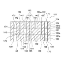
- FIG. 3 is a cross-sectional view taken along line III-III in FIG.
- FIG. 4 is a cross-sectional view taken along lines IV-IV and VV in FIG. 2.
- FIG. 7 is a cross-sectional view taken along line VII-VII in FIG. 6.
- FIG. 7 is a cross-sectional view taken along lines VIII-VIII and IX-IX in FIG.
- FIG. 10 is a cross-sectional view taken along lines XX and XI-XI in FIG. 9. It is a top view which shows the plate for levitation based on 4th Embodiment.
- FIG. 12 is a cross-sectional view taken along line XII-XII in FIG.
- FIG. 12 is a cross-sectional view taken along lines XIII-XIII and XIV-XIV in FIG.
- reference numerals of elements in the first embodiment are in the 100s
- reference numerals of elements in the second embodiment are in the 200s
- reference numerals of elements in the third embodiment are In the 400s
- the reference numerals of the elements in the fourth embodiment are indicated in the 500s
- the elements having the same reference numerals in the first to fourth embodiments are the same unless otherwise described. Shape and configuration.
- the dimension of the supported object 300 in the width direction is the both ends of the flying plates 103, 203, 403, and 503 in the width direction.
- the size is such that the air supply ports 151, 251, 451, and 551 provided in the section can be covered in a top (planar) view.
- FIG. 1 is a perspective view schematically showing a part of a coating apparatus 101 according to the embodiment
- FIG. 2 is a top (plan) view showing the levitation plate 103 shown in FIG. 1
- FIG. 4 is a cross-sectional view taken along line III-III in FIG. 2
- FIG. 4 is a cross-sectional view taken along lines IV-IV and VV in FIG. 2, and FIG. is there.
- the coating apparatus 101 of the embodiment mainly includes a slot nozzle 113 that constitutes a coating means for applying a coating solution such as a resist solution to a supported member 300 such as a glass substrate, and a slot nozzle 113.
- a non-contact support device 102 that is levitated and separated by a predetermined distance, and a control unit 130 that controls operations of the non-contact support device 102, the slot nozzle 113, and the like.
- the surface plate 111 has a rectangular parallelepiped shape, and a flat upper surface 111a includes a rectangular work area 112a in an upper surface (planar) view, and a support area 112b arranged with the work area 112a in between in the short direction of the upper surface 111a.
- the work area 112 a is an area where the coating liquid is applied by the slit nozzle 113 to the supported object 300 disposed on the upper surface 111 a of the surface plate 111, and the support area 112 b is used to convey the supported object 300. This is an area where a conventionally known transport means (not shown) is arranged.
- the upper surface 111a of the surface plate 111 of the present embodiment is separated into the work area 112a and the support area 112b by the boundary groove 104 extending in the longitudinal direction of the surface plate 111, but the surface plate without the boundary groove 104 is used. Needless to say, it can also be used.
- the supported object 300 is a rectangular thin plate member such as a glass substrate, and the edge located on the most downstream side in the transport direction is the front edge F, and is located on the most upstream side.
- the edge to be used is the rear edge E
- the left edge from the rear edge E toward the front edge F in the top (planar) view is the left edge L
- the right edge is the right edge R.
- the conveying means a configuration is used in which the left edge portion L and the right edge portion R of the supported object 300 are sucked and held and conveyed so as to face both the support regions 112b of the surface plate 111.
- the conveying means sucks and holds the left edge portion L and the right edge portion R of the supported object 300, and conveys them in a direction approaching the levitation plate 103 and a direction away from the levitation plate 103.
- the gantry 109 includes a horizontal holding portion 109a on which the slot nozzle 113 is mounted, and two support portions 109b that are continuous to both ends in the longitudinal direction of the horizontal holding portion 109a.
- Each support portion 109b extends in a direction perpendicular to the horizontal holding portion 109a, one end portion of each support portion 109b is connected to one end portion of the horizontal holding portion 109a, and the other end portion of each support portion 109b is It is fixed to the side surface 111b of the surface plate 111.
- the non-contact support device 102 includes a levitation plate 103 that is a levitation unit having a support surface 103a that supports the supported object 300 in a non-contact state by discharging gas toward the supported object 300, and the supported object.
- a suction means (not shown) for applying a suction force toward the support surface 103a to the 300 and a gas source (not shown) such as a pump for supplying compressed gas are provided.
- the suction means and the gas source are driven by a command signal from the control unit 130.
- the support object 300 By sucking the gas interposed between the support surface 103a and the support object 300 into the main levitation region 133 in the vicinity of the center region of the support surface 103a of the levitation plate 103, the support object 300 is moved toward the support surface 103a. Is provided on the upstream side of the main levitation region 133 with respect to the transport direction 149 in which the supported object 300 is transported (on the side opposite to the transport direction (the direction facing the transport direction 149)). Before the main suction force applied in the main levitation region 133 is applied to the extended first preliminary levitation region 131, a preliminary suction force is applied to the supported object 300 in the direction of the support surface 103a. A first preliminary suction circuit is provided.
- the second preliminary levitation region 135 on the downstream side (opposite conveyance direction side) of the main levitation region 133 with respect to the conveyance direction 149 is the main component in the direction of the support surface 103a with respect to the supported object 300.
- a second preliminary suction circuit for applying a preliminary suction force after the suction force is applied is provided.
- the coating area P where the coating liquid applied from the slit nozzle 113 reaches is disposed in the main levitation area 133.
- the application area P is a rectangular area defined by a line passing through the center of the suction port 139.
- the levitation plate 103 includes a top plate 104, a path configuration plate 181, and a bottom plate 183, and the top plate 104, the path configuration plate 181, and the bottom plate 183 are arranged from the side where the supported member 300 is located. It is fastened by a well-known fastening means in a state of being sequentially stacked.
- the main suction circuit disposed in the main levitation region 133 includes a suction port 139, an internal suction through-hole 140 communicating with the suction port 139, and a suction communicating with the internal suction through-hole 140. And a suction through hole 185 that connects the suction means (not shown) and the suction groove 155.
- the suction port 139 is a hole provided in the top plate 104 that penetrates in the thickness direction. One end portion opens to the supported member 300 side, and the other end portion opens to the path constituting plate 181 side. ing.
- the internal suction through port 140 is a hole that is provided in communication with the suction port 139 provided in the top plate 104 and penetrates the path forming plate 181 in the thickness direction.
- the suction groove 155 is a groove provided on the lower surface 181 a of the path configuration plate 181 and communicates with the internal suction through-hole 140.
- an internal suction passage 154 that connects the internal suction through-holes 140 to each other through the suction groove 155 is formed. Further, due to the internal suction passage 154 and the internal suction through-hole 140, only all the suction ports 139 extending into the main floating region 133 are in communication with each other.
- the bottom plate 183 has a suction through-hole 185 penetrating in the thickness direction (vertical direction in FIG. 3).
- the suction through-hole 185 is formed so as to communicate with the suction groove 155.
- the main suction circuit of the present embodiment includes a single suction through-hole 185. Accordingly, the suction force from the suction means (not shown) in the main suction circuit is transferred from the single suction through-hole 185 in the main suction circuit through the internal suction passage 154 and each internal suction through-hole 140, and then to each suction port. 139 to the supported object 300.
- the first preliminary suction circuit is arranged in the first preliminary levitation region 131 (see FIG. 2) located on the upstream side of the main levitation region 133 with respect to the transport direction 149. Similar to the main suction circuit, the first preliminary suction circuit communicates the suction port 137, the internal suction through-hole 138 communicating with the suction port 137, and the internal suction through-hole 138 from the side where the supported object 300 is located. And a suction through hole 184 that connects the suction means (not shown) and the suction groove 153 (see FIG. 4).
- the suction port 137 is a hole that is provided in the top plate 104 and penetrates in the thickness direction. One end portion opens to the supported member 300 side, and the other end portion opens to the path forming plate 181 side. ing.
- the internal suction through-hole 138 is a hole that is provided in communication with the suction port 137 provided in the top plate 104 and penetrates the path constituting plate 181 in the thickness direction.
- the suction groove 153 is a groove provided on the lower surface 181 a of the path configuration plate 181, and the internal suction through holes 138 communicate with each other by joining the lower surface 181 a of the path configuration plate 181 to the upper surface 183 a of the bottom plate 183.
- An internal suction passage 152 is formed. Further, only the suction ports 137 disposed in the first preliminary floating region 131 are communicated with each other by the internal suction passage 152 and the internal suction through-hole 138.
- the bottom plate 183 has a suction through-hole 184 that penetrates in the thickness direction (vertical direction in FIG. 4).
- the suction through-hole 184 is formed so as to communicate with the suction groove 153.
- the first preliminary suction circuit of this embodiment includes a single suction through-hole 184. Accordingly, the suction force from the suction means (not shown) is applied to each suction port 137 via the single suction through-hole 184, each internal suction passage 152 and each internal suction through-hole 138 disposed in the first preliminary suction circuit.
- the main suction circuit and the first preliminary suction circuit are completely separate circuits that do not have a communicating portion, the suction forces from the two suction circuits are individually independent of each other. It can be applied to the supported object 300.
- a second preliminary suction circuit is arranged in the second preliminary levitation area 135 located downstream of the main levitation area 133 in the transport direction 149. Similar to the first preliminary suction circuit described above, from the side where the supported object 300 is located, the suction port 141, the internal suction through-hole 142 communicating with the suction port 141, and the suction groove communicating with the internal suction through-hole 142 157 and a suction through hole 186 that connects a suction means (not shown) and the suction groove 157.
- the suction port 141 is a hole provided in the top plate 104 penetrating in the thickness direction, one end opening to the supported member 300 side, and the other end opening to the path constituting plate 181 side. ing.
- the internal suction through-hole 142 is a hole that is provided in communication with the suction port 141 provided in the top plate 104 and penetrates the path forming plate 181 in the thickness direction.
- the suction groove 157 is a groove provided on the lower surface 181 a of the path configuration plate 181, and the internal suction through holes 142 communicate with each other by joining the lower surface 181 a of the path configuration plate 181 to the upper surface 183 a of the bottom plate 183.
- An internal suction passage 156 is formed. Further, only the suction port 141 extending into the second preliminary floating region 135 is communicated with each other by the internal suction passage 156 and the internal suction through-hole 142.
- the bottom plate 183 has a suction through-hole 186 that penetrates in the thickness direction (vertical direction in FIG. 4).
- the suction through-hole 186 is formed so as to communicate with the suction groove 157.
- the second preliminary suction circuit of this embodiment includes a single suction through-hole 186. Accordingly, a suction force from a suction means (not shown) is applied to the supported object 300 from each suction port 141 via the single suction through-hole 186, each internal suction passage 156, and each internal suction through-hole 142.
- the main suction circuit and the first and second preliminary suction circuits are separate circuits, the suction force from the suction circuit can be individually applied to the supported object 300 independently of each other.
- the main levitation region 133, the first preliminary levitation region 131, and the second preliminary levitation region 135 are configured to be able to apply a suction force to the supported object independently of each other.
- the levitation plate 103 is provided with a first air supply circuit for discharging a compressed gas that levitates the supported object 300.
- the first air supply circuit includes an air supply port 145 disposed in the main levitation region 133 and an air supply disposed in the first and second preliminary levitation regions 131 and 135.
- Ports 143, 147, air supply grooves 161 that connect the air supply ports 143, 145, 147, an internal air supply through port 160 that communicates with the air supply port 145, And an air supply through-hole 163 communicating with the air through-hole 160.
- the air supply port 145 is a hole provided in the top plate 104 penetrating in the thickness direction, one end opening to the supported member 300 side, and the other end opening to the path constituting plate 181 side. is doing.
- the internal air supply through port 160 is provided in the path configuration plate 181 so as to communicate with one of the plurality of air supply ports 145, and penetrates in the thickness direction of the path configuration plate 181. Furthermore, the air supply through port 163 penetrates in the thickness direction of the bottom plate 183 and communicates with the internal air supply through port 160.
- the air supply groove 161 is a groove provided on the upper surface 181b of the path configuration plate 181.
- the air supply ports 143, 145, An internal air supply passage 162 communicating with each other is formed.
- a single internal air supply through port 160 and an air supply through port 163 are provided, and the other air supply ports 143, 145, and 147 communicate with each other through the internal air supply passages 162.
- another air supply circuit is provided around the main levitation region 133 and the first and second preliminary levitation regions 131 and 135. That is, the second air supply circuit is arranged along the longitudinal edge (the edge extending in the direction parallel to the transport direction 149) of the upper surface 103a of the levitation plate 103, and the third air supply circuit is arranged in the short direction. It is arranged along the edge (edge extending in the direction perpendicular to the conveyance direction 149).
- the second air supply circuit is arranged on both the left and right sides (upper and lower sides in FIG. 2) in the transport direction 149, and one second air supply circuit is on the left side (upper side in FIG. 2) in the transport direction 149.
- the air supply ports 151, 173, 175, 177, and 151 that are positioned, the air supply groove 174 that connects these air supply ports 151, 173, 175, 177, and 151, and the single that communicates with the air supply port 175.
- the air supply groove 174 is a groove provided on the upper surface 181b of the path configuration plate 181.
- the air supply port 151, 173, 175, 177 and 151 are formed as internal air supply passages 172 communicating with each other. Accordingly, compressed gas supplied from a gas source (not shown) is supplied to each of the air supply ports 151, 173, 175, 177 and 151 via the air supply through port 189, the internal air supply through port 176, and the internal air supply passage 172.
- the other second air supply circuit located on the right side (lower side in FIG. 2) in the transport direction 149 has the same configuration.
- the third air supply circuit is disposed along the short-side edge of the support surface 103a of the levitation plate 103, and is located on the upstream side and the downstream side (left and right sides in FIG. 2) with respect to the transport direction 149, respectively.
- One third air supply circuit arranged on the upstream side includes an air supply port 152, an air supply groove 156 that connects the air supply ports 152 to each other, and a passage configuration plate 181 that communicates with the air supply port 152.
- An internal air supply through port (not shown), an internal air supply through port, and an air supply through port (not shown) that penetrates the bottom plate 183 are provided.
- the configuration of the air supply groove 156, the internal air supply through port, the air supply through port, and the like are formed in the same manner as the first and second air supply circuits.
- the other third air supply circuit arranged on the downstream side has the same configuration.
- compressed gas is supplied from a gas source (not shown), and compressed gas is discharged from each air supply port.
- the first to third air supply circuits are configured to supply compressed gas from different gas sources, but can be appropriately changed to a configuration in which the gas is supplied from a single gas source.
- the supported object 300 advances along the transport direction 149, and for example, the end side (the transport direction 149) of the suction ports 137 arranged in two rows in the direction perpendicular to the transport direction 149 of the first preliminary floating region 131.
- the front edge F reaches a position partially covering the suction port 137 existing in the first preliminary levitation region 131 such as to cover the suction port 137 of only one row located on the downstream side
- a floating force by compressed gas ejected from the air supply ports 143, 151, and 152 is applied to the object 300, and a suction force from the suction port 137 is applied.
- the supported object 300 advances along the transport direction 149 and covers all of the suction ports 137 existing in two rows in the direction perpendicular to the transport direction 149 in the top surface (planar) view of the first preliminary floating region 131.
- a predetermined support rigidity force can be obtained, and a predetermined support rigidity 103 can be obtained from the support surface 103a of the levitation plate 103.
- the supported object 300 is supported in a non-contact manner in a state of being lifted (separated) by a distance. In this state, the portion of the supported object 300 that extends to the first preliminary levitation region 131 floats in the longitudinal direction of the supported object 300 (the direction in which the front edge portion F or the rear edge portion E extends). Variations in quantity are eliminated.
- the supported object 300 advances downstream in the transport direction 149, and the front edge F is arranged in three rows in the vertical direction with respect to the transport direction 149 in the top surface (planar) view of the levitation plate 103.
- the main levitation region 133 is entered until all of the suction ports 139 constituting the end row of the main levitation region 133 on the downstream side in the conveying direction 149 are covered.
- the suction force supplied from a part of the suction ports 139 and the lift force supplied from a part of the air supply port 145 are arranged in the main levitation region 133 and communicate with each other. It will be in the state which has received.
- the supported object 300 since the supported object 300 is arranged in the main levitation region 133 and covers some of the suction ports 139 in plan view, it extends to the main levitation region 133. Since the predetermined suction force is not applied to the portion including the leading edge portion F, the predetermined support rigidity force is not applied.
- the supported object 300 is disposed in the first preliminary levitation region 131 and covers all the suction ports 137 communicating with each other, and thus extends to the first preliminary levitation region 131.
- a predetermined support rigidity force is obtained at the portion of the supported object 300. Accordingly, even in a portion including the front edge F extending to the main floating region 133 of the supported object 300, the predetermined flying height of the portion of the supported object 300 extending to the first preliminary floating region 131 is substantially the same. Non-contact support is possible with a flying height of. As a result, the coating liquid can be applied from the slit nozzle 113 to the supported object 300 with a desired accuracy.
- the front edge F is located at a position where the supported object 300 further advances downstream in the conveying direction 149 and the supported object 300 covers all of the suction ports 139 arranged in communication with the main floating region 133 in plan view. In this state, the non-contact support is performed with a predetermined flying height as described above.
- the supported object 300 further advances downstream in the conveying direction 149, and the rear edge E of the supported object 300 is arranged in three rows in the direction perpendicular to the conveying direction 149.
- a part of the suction port 139 in the main levitation region 133 is supported by the supported object 300.
- a predetermined suction force cannot be supplied to a portion of the supported object 300 extending to the main levitation region 133 and a predetermined support rigidity force cannot be obtained.
- the second preliminary levitation region 135 of the support object 300 is covered.
- a predetermined support rigidity force can be obtained at the extended portion. Therefore, although the suction ports 139 arranged in communication with each other in the main levitation region 133 are not covered, the supported object 300 has a predetermined levitation amount or a levitation amount substantially close to it. Contact supported. Therefore, it is possible to apply the coating liquid from the slit nozzle 113 to the supported object 300 with a desired accuracy.
- the number and diameter of the suction ports 139 arranged in the main levitation region 133 are the same as those in the processing region where the processing of the supported object 300 is performed using the non-contact support device 102, that is, the coating region P. It is preferable to set so as to be within a rectangle defined by a line passing through the center of the suction port 139 arranged in the region 133.
- the suction by the main suction circuit, the first and second preliminary suction circuits, and the supply by the first to third supply circuits are performed in the plan view of the support surface 103a of the levitation plate 103. Is controlled by the control unit 130 so as to be started before even a part of the intake or supply ports constituting each circuit is covered. Further, the first and second preliminary suction circuits can be selectively used.
- FIG. 6 is a plan view showing the levitation plate 203 according to the second embodiment
- FIG. 7 is a cross-sectional view taken along line VII-VII in FIG. 6
- FIG. 8 is a line VII in FIG. -VII is a cross-sectional view taken along line IX-IX.
- the floating plate 203 of the non-contact support device according to the second embodiment is the center of the region of the floating plate 103 according to the first embodiment through which the left and right edge portions L and R of the supported object 300 pass.
- the side main levitation area 265 is provided in the section, and first and second side preliminary levitation areas 264 and 269 are provided on the upstream side and the downstream side of the side main levitation area 265 in the transport direction 249, respectively.
- the non-contact support device according to the second embodiment has the same configuration as the non-contact support device 102 of the first embodiment except for the floating plate 203. Therefore, the configuration, effects, and the like of the second embodiment that are not particularly described are the same as those of the first embodiment.
- the levitation plate 203 is the same as the levitation plate 103 of the first embodiment, the main suction circuit disposed in the main levitation region 233, and the first and second preliminary levitation regions 231 and 235. And a second preliminary suction circuit. Further, the levitation plate 203 includes a side main suction circuit disposed in the side main levitation region 265, a first side preliminary suction circuit disposed in the first side preliminary levitation region 264, and a second side suction circuit. A second side preliminary suction circuit is provided in the side preliminary levitation area 269.
- the side main levitation area 265 is located away from the application area P (see FIG. 2) and the main levitation area 233, which are processing areas, in a direction crossing the transport direction 249, that is, supported.
- the object 300 (see FIG. 5) is disposed at a position where the left edge portion L and the right edge portion R side pass.
- the first and second side preliminary levitation regions 264 and 269 are separated from the first and second preliminary levitation regions 231 and 235 in the direction intersecting the transport direction 249, the supported object 300 (FIG. 5) is disposed at a position where the left edge portion L and the right edge portion R side pass.
- the side main levitation area 265 has side main levitation areas 265a and 265b on the left and right ends as viewed in the transport direction 249, and the side main suction circuits are arranged in the areas 265a and 265b, respectively. . As shown in FIG.
- the suction through hole 286a is connected to a suction means (not shown), and the suction force is formed by the suction through hole 286a, the suction groove 284a, and the upper surface 283a of the bottom plate 283. Is provided from the suction port 267a through the internal suction passage 291a and the internal suction through-hole 282a.
- Each of the left and right side main suction circuits has a single suction through-hole 286, and the suction force to the two suction ports 267 passes from the suction through-hole 286 to the internal suction through-hole 282 and the internal suction passage 291. Is granted through.
- the side main suction circuits in the left and right side main levitation regions 265 are separate circuits separated from each other, the suction force can be applied individually and independently.
- a first side preliminary levitation area 264 is arranged on the upstream side of the side main levitation area 265 in the transport direction 249.
- a suction port 263 for sucking gas and an air supply port 273 for discharging gas are arranged in the first lateral preliminary floating region 264.
- the first side preliminary levitation area 264 has first side preliminary levitation areas 264a and 264b on the left and right ends when viewed in the transport direction 249, and the same first levitation area 264a and 264b has the same first first.
- a side pre-suction circuit is provided. As shown in FIG.
- the side preliminary suction circuit disposed in the first side preliminary floating region 264a (264b) disposed on the left side (right side) includes two suction ports 263a (263b) and a suction port.
- the suction through-hole 293 is connected to a suction unit (not shown), and suction force is applied from the suction port 263 via the suction through-hole 293 and the internal suction through-hole 291.
- the suction ports 263a and 263b can be independent from each other.
- a suction force can be applied individually.
- region 269 is arrange
- the same second lateral preliminary suction circuits are respectively provided in the same manner as the first lateral preliminary levitation area 264.
- a suction port 271 for sucking gas and an air supply port 277 for discharging gas are arranged in the second side preliminary floating region 269.
- the second side preliminary suction is disposed in the second side preliminary floating region 269a (269b) on the left side (right side).
- the circuit communicates with the suction port 271a (271b) and the suction port 271a (271b), communicates with the internal suction through-hole 291 penetrating in the thickness direction of the path forming plate 281, and the internal suction through-hole 291; And a suction through hole 293 penetrating in the thickness direction of H.283.
- the suction through-hole 293 is connected to a suction means (not shown), and a suction force is applied from the suction port 271 disposed on the plate via the suction through-hole 293 and the internal suction through-hole 291.
- the suction ports 271a and 271b are independent from each other. Individual suction can be applied.
- the front edge F is located at a position where the supported object 300 advances along the conveying direction 249 along the suction port 237 of the first preliminary floating region 231 and the suction port 263 of the first lateral preliminary floating region 264.
- the floating force by the compressed gas ejected from the air supply ports 243, 251, and 252 is applied, and the suction force from the suction ports 237 and 263 is applied.
- the flying height of the left and right edge portions L and R of the supported object 300 is smaller than the inner side of the supported portion 300 in the short direction. Variations can occur.
- the floating plate The supported object 300 is supported in a non-contact manner in a state of being separated from the support surface 203a of 203 by a predetermined distance.
- the supported object 300 is in a position to cover all the suction ports 237 and 263 in the first preliminary levitation region 231 and the first lateral preliminary levitation region 264 in a plan view, and from the suction ports 237 and 263 at a predetermined exhaust velocity. This is because the gas is discharged and a predetermined suction force is applied to the supported object 300.
- the short direction (the front edge F or the rear edge of the supported object 300). Variation in the flying height in the direction in which the edge E extends) is suppressed.
- the supported object 300 advances downstream in the transport direction 249, and the front edge F enters the main levitation region 233 and the side main levitation region 265 in plan view of the levitation plate 203.
- the suction force supplied from a part of the suction ports 239 and 267 arranged in the main levitation region 233 and the side main levitation region 265 and the levitation force supplied from a part of the air supply ports 245 and 275 It will be in the state which has received.
- the supported object 300 is in a state where the suction ports 239 and 267 of the main levitation region 233 and the side main levitation region 265 are covered, so the main levitation region 233 and the side main levitation region A predetermined suction force is not applied to the portion including the front edge F extending to H.265.
- the supported object 300 covers the suction port 237 of the first preliminary levitation region 231 and the suction port 263 of the first side preliminary levitation region 264 in plan view, the first preliminary A portion of the supported object 300 that extends to the floating region 231 and the first lateral preliminary floating region 264 has a predetermined support rigidity. Therefore, the part including the front edge F extending to the main levitation region 233 and the side main levitation region 265 of the supported object 300 can be supported in a non-contact manner with substantially the same levitation amount as the predetermined levitation amount. Furthermore, even when the left and right edge portions L and R of the supported object 300 are compared with the inner portions in the width direction, the variation in the flying height can be further suppressed. Therefore, it is possible to apply the coating liquid with a desired accuracy in the width direction of the supported object 300 from the slit nozzle 113.
- the supported object 300 further proceeds downstream in the transport direction 249, and the supported object 300 covers all of the suction ports 239 and 267 arranged in the main floating region 233 and the side main floating region 265 in a plan view.
- the front edge F When the front edge F reaches the position, it is supported in a non-contact manner with a predetermined flying height as described above.
- the supported object 300 further proceeds downstream in the conveying direction 249, the trailing edge E of the supported object 300 enters the main levitation region 233 and the side main levitation region 265, and the main levitation region 233 and the side main levitation region.
- a predetermined suction force is applied to the supported object 300 in the main levitation region 233 and the side main levitation region 265. It cannot be applied and a predetermined support rigidity force cannot be obtained.
- the supported object 300 since the supported object 300 is in a state of covering all the suction ports 241 and 271 arranged in the second preliminary floating region 235 and the second lateral preliminary floating region 269 in plan view, A predetermined supporting rigidity force is obtained at a portion extending to the second preliminary floating region 235 and the second lateral preliminary floating region 269. Therefore, although the suction ports 239 and 267 arranged in the main levitation region 233 and the side main levitation region 265 are not partially covered, the supported object 300 has a predetermined levitation amount or almost the same. Non-contact support with a close flying height. Therefore, it is possible to apply the coating liquid from the slit nozzle 113 to the supported object 300 with a desired accuracy.
- the levitation plate 203 includes the side main suction circuit and the first and second side preliminary suction circuits. Therefore, the levitation plate 203 is further supported as compared with the case where the levitation plate 103 of the first embodiment is used.
- part on the left edge part L of 300 and the right edge part R side can be heightened.
- the floating plate 103 according to the first embodiment is used, the floating amount of the supported object 300 slightly varies on the left and right edge portions L and R in the width direction of the supported object 300 compared to the inner side in the width direction. The tendency to occur is seen.
- the structure which actuates one or both of the side main suction circuits of the left and right side main levitation regions 265a and 265b In addition to the side main suction circuit, the configuration of operating one or both of the first and second side preliminary suction circuits of the first and second side preliminary floating regions 264 and 269 can be appropriately changed.
- the suction by the main suction circuit, the first and second preliminary suction circuits, the side main suction circuit, the first and second side preliminary suction circuits, and the air supply by the first to third air supply circuits The control unit (see FIG. 1) is started before a part of the intake or supply ports constituting each circuit is covered by the supported object 300 in plan view of the support surface 203a of the levitation plate 203. Controlled by reference numeral 130).
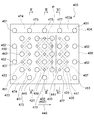
- FIG. 9 is a plan view showing a levitation plate 403 according to the third embodiment
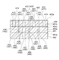
- FIG. 10 is a cross-sectional view taken along lines XX and XI-XI in FIG.
- the cross section taken along line III-III in FIG. 9 is the same as the cross sectional view of the levitating plate 103 of the first embodiment shown in FIG. 3, so FIG. 3 will be referred to as necessary.
- the levitation plate 403 according to the third embodiment includes a main suction circuit and first and second preliminary suction circuits, similarly to the levitation plate 103 according to the first embodiment shown in FIG.
- an air supply port 445 disposed in the main levitation region 433, an air supply port 443 disposed in the first preliminary levitation region 431, and an air supply port 447 disposed in the second preliminary levitation region 435 are provided.
- the compressed gas can be supplied independently from each other.
- the air supply circuits of the main levitation region 421, the first preliminary levitation region 431, and the second preliminary levitation region 435 are configured as separate circuits and can supply compressed gas independently.
- the suction circuit of the present embodiment is the same as the suction circuit according to the first embodiment, and the details are omitted.
- a main air supply circuit for applying a suction force to the supported object 300 is provided in the main floating area 433 of the support surface 403a of the floating plate 403, and the main floating area in the conveyance direction 449 in which the supported object 300 is conveyed.
- a first preliminary air supply circuit for applying a levitation force is provided in the first preliminary levitation region 431 extending to the upstream side of 433.
- a second preliminary air supply circuit is provided in the second preliminary floating region 435 on the downstream side of the main floating region 433 in the transport direction 449.
- the main air supply circuit disposed in the main levitation region 433 includes an air supply port 445 and an air supply groove 421 that connects the air supply port 445 to each other (see reference numeral 161 in FIG. 3). ), An internal air supply through-hole connected to the air supply groove 421 (see reference numeral 160 in FIG. 3), and an air supply through-hole connected to a gas source (not shown) (see reference numeral 163 in FIG. 3). And). Therefore, compressed gas from a gas source (not shown) is an air supply through port (see reference numeral 163 in FIG. 3), which is a main air supply circuit, and an internal air supply through port (see reference numeral 160 in FIG. 3). ) And the air supply groove 421, and is applied to the supported object 300 from each air supply port 445.
- the first preliminary air supply circuit is arranged in the first preliminary floating region 431 located on the upstream side of the main floating region 433 with respect to the transport direction 449.
- the first preliminary air supply circuit is similar to the main air supply circuit in that the air supply port 443, the air supply groove 423 that connects the air supply port 443 to each other, and the air supply groove 423 are provided.
- An internal air supply through-hole 427 communicating with the internal air supply through-hole 427 and an air supply through-hole 429 connecting a gas source (not shown).
- the air supply port 443 is a hole provided in the top plate 404 penetrating in the thickness direction, one end opening to the supported member 300 side, and the other end opening to the path constituting plate 481 side. is doing.
- the internal air supply through port 427 is a hole that connects to the air supply groove 423 provided on the upper surface 481b of the path configuration plate 481 and penetrates the path configuration plate 481 in the thickness direction.
- the bottom plate 483 has an air supply through port 429 that penetrates in the thickness direction (vertical direction in FIG. 10).
- the air supply through port 429 is formed so as to communicate with the internal air supply through port 427.
- the first preliminary suction circuit of the present embodiment includes a single air supply through port 429 and a single internal air supply through port 427. Accordingly, compressed gas supplied from a gas source (not shown) passes through the supply air through-hole 429 and the internal supply air through-hole 427 and is ejected from each supply air port 443 through the internal air supply passage 426. Further, since the main air supply circuit and the first preliminary air supply circuit described above are separate air supply circuits that are separated from each other, the levitation force from both air supply circuits is individually and independently supported 300. Can be granted.
- a cross-sectional view taken along line XI-XI in FIG. 9 is the same as the cross-sectional view taken along line XX in FIG. 9 and will be described with reference to FIG.
- reference numerals of elements of the second preliminary air supply circuit are enclosed in square brackets ([]).
- the second preliminary air supply circuit is arranged in the second preliminary levitation region 435 located on the downstream side of the main levitation region 433 in the transport direction 449.
- the air supply port 447, the air supply groove 425 that communicates with the air supply port 447, and the air supply groove 425 are communicated. It has the single internal air supply through-hole 428 and the single air supply through-hole 430 which connects the internal air supply through-hole 428 and a gas source not shown.
- the air supply port 447 is a hole provided in the top plate 404 that penetrates in the thickness direction. One end portion opens to the supported member 300 side, and the other end portion opens to the path constituting plate 481 side. is doing.
- the internal air supply through port 428 is a hole that connects to the air supply groove 425 provided on the upper surface 481b of the path configuration plate 481 and penetrates the path configuration plate 481 in the thickness direction.
- the bottom plate 483 has an air supply through hole 430 that penetrates in the thickness direction (vertical direction in FIG. 10).
- the air supply through port 430 is formed so as to communicate with the internal air supply through port 428.
- the second preliminary air supply circuit of the present embodiment includes a single air supply through port 430 and an internal air supply through port 428. Accordingly, compressed gas supplied from a gas source (not shown) passes through the supply air through-hole 430 and the internal supply air through-hole 428, and from each supply air port 447 to the supported object 300 via the internal air supply passage 432. Is granted. Further, since the main air supply circuit and the first and second preliminary air supply circuits are separate circuits, the levitation force from the air supply circuit is individually and independently supported 300. Can be granted.
- the supported object 300 advances along the transport direction 449 and covers all of the air supply port 443 and the suction port 437 in a plan view of the first preliminary levitation region 431, a predetermined distance from the support surface 403 a of the levitation plate 403 is obtained.
- the supported object 300 is supported in a non-contact manner in a state of being separated by a distance.
- the supported object 300 is in a position to cover all the air supply ports 443 and the suction ports 437 in the first preliminary levitation region 431 in a plan view, and the levitation force by the gas of a predetermined pressure discharged from the air supply port 443 and the suction This is because a predetermined suction force due to the gas being discharged from the port 437 at a predetermined exhaust speed is applied to the supported object 300.
- the portion of the supported object 300 extending to the first preliminary levitation region 431 is levitated in the longitudinal direction of the supported object 300 (the direction in which the front edge portion F or the rear edge portion E extends). Variations in quantity are eliminated.
- the supported object 300 advances downstream in the transport direction 449, and the front edge F enters the main levitation region 433 in plan view of the levitation plate 403.
- the suction force supplied from a part of the suction ports 439 arranged in the main levitation region 433 and the lift force supplied from a part of the air supply port 445 are received. That is, since the supported object 300 is in a state where a part of the suction ports 439 and the air supply ports 445 of the main levitation region 433 are covered in plan view, the front object F extending to the main levitation region 433 is included. A predetermined levitation force and suction force are not applied to the part.
- the object to be supported 300 covers all the suction port 437 and the air supply port 443 of the first preliminary levitation region 431 in plan view, the supported object 300 extends to the first preliminary levitation region 431.
- a predetermined support rigidity force is obtained at the part of the object 300. Therefore, the part including the front edge F extending to the main flying region 433 of the supported object 300 can be supported in a non-contact manner with a flying height that is substantially the same as the predetermined flying height.
- the coating liquid can be applied to the supported object 300 from the slit nozzle (see reference numeral 113 in FIG. 1) with a desired accuracy.
- the front edge portion is located at a position where the supported object 300 further proceeds downstream in the conveying direction 449 and covers the suction port 439 and the air supply port 445 arranged in the main floating region 433 in plan view. In the state where F has reached, it is supported in a non-contact manner with a predetermined flying height as described above.
- the supported object 300 further advances downstream in the transport direction 449, the trailing edge E of the supported object 300 enters the main levitation region 433, and part of the suction port 439 and the air supply port 445 in the main levitation region 433.
- the main levitation region 433 cannot supply a predetermined suction force and levitation force to the supported object 300, and a support rigidity force cannot be obtained.
- the supported object 300 covers all the suction ports 441 and the air supply ports 447 arranged in the second preliminary floating region 435 in plan view, the second preliminary floating region 435 of the supported object 300 is covered.
- a predetermined support rigidity force is obtained at a portion extending in the direction. Therefore, although the suction port 439 arranged in the main levitation region 433 is not partially covered, the supported object 300 is supported in a non-contact manner with a predetermined levitation amount or a levitation amount almost similar to the predetermined levitation amount. .
- the coating liquid can be applied from the slit nozzle 113 to the supported object 300 with a desired accuracy.
- the suction by the main suction circuit and the first and second preliminary suction circuits and the supply by the main air supply circuit and the first and second preliminary suction circuits are a plan view of the support surface 403a of the levitation plate 403.
- the control unit (see reference numeral 130 in FIG. 1) starts the process so that the object to be supported 300 starts before the opening of the intake and supply ports is partially covered.
- each of the first and second preliminary suction circuits and the first and second preliminary air supply circuits can be selectively used.
- the main air supply circuit and the first air supply circuit are compared with the non-contact support device using the levitation plate 103 according to the first embodiment. Since the air is supplied by the second preliminary air supply circuit, the flying height can be controlled with high accuracy.
- the control unit starts the process before the support object 300 covers even a part of the intake or supply ports constituting each circuit.
- FIG. 11 is a plan view showing a levitation plate 503 according to the fourth embodiment
- FIG. 12 is a cross-sectional view taken along line XII-XII in FIG. 11
- FIG. 13 is a line XIII in FIG. -XIII is a cross-sectional view taken along line XIV-XIV.
- the levitation plate 503 of the non-contact support device according to the fourth embodiment is similar to the levitation plate 203 according to the second embodiment shown in FIG. 6, and includes a main suction circuit, first and second preliminary suctions.
- the side main suction circuit, and the first and second side preliminary suction circuits the side main air supply circuit and the first and second side air circuits in the side main levitation region 565 are provided.
- First and second side preliminary air supply circuits are provided in the preliminary levitation areas 564 and 569. That is, the levitation plate 503 of the non-contact support device according to the fourth embodiment includes the same suction circuit as the levitation plate 203 of the second embodiment, and is the same main as the levitation plate 403 of the third embodiment. An air supply circuit and first and second preliminary air supply circuits are provided. Therefore, the side main air supply circuit of the levitation plate 503 and the first and second side preliminary air supply circuits will be mainly described.
- the lateral main levitation area 565 of the levitation plate 503 has lateral main levitation areas 565a and 565b on the left and right ends as viewed in the transport direction 549, and the lateral main suction circuit and the side are provided in the respective areas 565a and 565b.
- a main air supply circuit is arranged. As shown in FIG. 11, in the side main levitation region 565a (565b) arranged on the left (or right) side, one side main suction circuit (or the other side) is provided as in the second embodiment. Main suction circuit) and one side main air supply circuit (or the other side main air supply circuit).
- the side main air supply circuit includes an air supply port 575a (575b), an internal air supply through port 576a (576b) that communicates with the air supply port 575a (575b) and penetrates the path configuration plate 581, and an internal air supply through.
- An air supply through-hole 589a (589b) that communicates with the port 576a (576b) and penetrates the bottom plate 583 in the thickness direction thereof.
- the air supply through port 589a is connected to a gas source (not shown) and compressed from the air supply port 575a via the air supply through port 589a and the internal air supply through port 576a. Gas is applied.
- the air supply through holes 589a and 589b of the left and right side main air supply circuits are separate air supply circuits. Therefore.
- a suction port 563 for sucking a gas and an air supply for discharging the gas are provided in the first side preliminary floating region 564 located upstream with respect to the conveyance direction 549 of the side main floating region 565.
- a mouth 573 is arranged. As shown in FIG.
- the first side preliminary air supply circuit disposed in the left side (right side) first side preliminary floating region 564a (564b) includes an air supply port 573a (573b) and an air supply
- the internal air supply through hole 522a (522b) that communicates with the port 573a (573b) and penetrates in the thickness direction of the path forming plate 581 and the internal air supply through hole 522a (522b), and the thickness of the bottom plate 583 And an air supply through hole 524a (524b) penetrating in the direction.
- the air supply through port 524a (524b) is connected to a gas source (not shown), and compressed gas is supplied from the air supply port 573a (573b) through the air supply through port 524a (524b) and the internal air supply through port 522a (522b). Is granted.
- the first side preliminary air supply circuits arranged on the left and right sides in the transport direction 549 are separate circuits, so that the first and second side parts separated from each other in the left and right end regions with respect to the transport direction 549 are separated.
- the side preliminary air supply circuits can apply individual levitation forces independently of each other.
- the same second side preliminary air supply circuit is arranged in the second side preliminary levitation regions 569a and 569b arranged on the left and right sides in the transport direction 549. ing.
- the second side preliminary air supply circuit arranged in the left side (right side) second side preliminary levitation region 569a (569b) is denoted by reference numerals enclosed in square brackets ([]) in FIG. As shown, an air supply port 577a (577b), an internal air supply through hole 578a (578b) that communicates with the air supply port 577a (577b) and penetrates in the thickness direction of the path constituting plate 581, and an internal air supply through-hole.
- An air supply through-hole 526a (526b) that communicates with the port 578a (578b) and penetrates in the thickness direction of the bottom plate 583 is provided.
- the air supply through port 526a (526b) is connected to a gas source (not shown), and compressed gas is supplied from the air supply port 577a (577b) through the air supply through port 526a (526b) and the internal air supply through port 578a (578b). Is granted. Therefore, by using the second side preliminary air supply circuits in the left and right second side preliminary levitation regions 569a (569b), the levitation force is individually applied independently from the air supply ports 577a and 577b. it can.
- the supported object 300 advances along the conveying direction 549 and is positioned so as to partially cover the suction port 537 of the first preliminary floating region 531 and the suction port 563 and the air supply port 573 of the first lateral preliminary floating region 564.
- levitation force due to the compressed gas ejected from the air supply ports 543, 551, and 552 is applied to the supported object 300, and suction force from the suction ports 537 and 563 is applied.
- the suction port 563 and the air supply port 573 are not entirely covered, the flying height of the left and right edge portions L and R of the supported object 300 is short of the supported portion 300. There may be variations compared to the inside of the direction.
- the supported object 300 advances along the conveying direction 549, and the suction ports 537 and 563 and the air supply ports of the first preliminary floating region 531 and the first lateral preliminary floating region 564 in the plan view of the floating plate 503 are provided.
- the supported object 300 is supported in a non-contact manner in a state of being separated from the support surface 503a of the floating plate 503 by a predetermined distance.
- the supported object 300 is in a position to cover all the suction ports 537 and 563 and the air supply ports 543 and 573 in the first preliminary floating region 531 and the first lateral preliminary floating region 564 in a plan view.
- a predetermined levitation force is applied to the supported object 300 from 543 and 573, and gas is discharged from the suction ports 537 and 563 at a predetermined exhaust speed, and a predetermined suction force is applied to the supported object 300.
- the short direction of the supported object 300 (the front edge F or the rear edge). Variation in the flying height in the direction in which the edge E extends) is suppressed.
- the supported object 300 advances downstream in the conveying direction 549, and the front edge F enters the main levitation region 533 and the side main levitation region 565 in plan view of the levitation plate 503.
- the suction force supplied from a part of the suction ports 539 and 567 arranged in the main levitation region 533 and the side main levitation region 565 and the levitation force supplied from a part of the air supply ports 545 and 575 are received. It will be in the state.
- the main floating region A predetermined suction force and levitation force are not applied to the portion including the front edge F extending to 533 and the side main levitation region 565.
- the supported object 300 covers all of the suction port 537 and the air supply port 543 of the first preliminary floating region 531 and the suction port 563 and the air supply port 573 of the first lateral preliminary floating region 564. Therefore, the portion of the supported object 300 extending to the first preliminary levitation region 531 and the first lateral preliminary levitation region 564 has a predetermined support rigidity. Therefore, the part including the front edge F extending to the main levitation region 533 and the side main levitation region 565 of the supported object 300 can be supported in a non-contact manner with substantially the same levitation amount as the predetermined levitation amount.
- the supported object 300 further advances downstream in the transport direction 549, and the suction objects 539 and 567 and the air supply ports in which the supported object 300 is disposed in the main floating region 533 and the side main floating region 565 in a plan view.
- non-contact support is performed with a predetermined flying height.
- the supported object 300 further advances downstream in the transport direction 549, the trailing edge E of the supported object 300 enters the main levitation region 533 and the side main levitation region 565, and the main levitation region 533 and the side main levitation region.
- the suction ports 539 and 567 and the air supply ports 545 and 575 reach the position that is not covered by the supported object 300, the main floating region 533 and the side main floating region 565 are connected to the supported object 300.
- a predetermined suction force and levitation force cannot be applied, and a predetermined support rigidity force cannot be obtained.
- the supported object 300 is positioned so as to cover all the suction ports 541 and 571 and the air supply ports 547 and 577 arranged in the second preliminary floating region 535 and the second lateral preliminary floating region 569 in a plan view.
- a predetermined support rigidity force is obtained at a portion of the supported object 300 that extends to the second preliminary levitation region 535 and the second side preliminary levitation region 569. Accordingly, the supported object 300 is in a state where the suction ports 539 and 567 and the air supply ports 545 and 575 arranged in the main levitation region 533 and the side main levitation region 565 are not covered.
- the coating liquid can be applied to the supported object 300 from the slit nozzle (see reference numeral 113 in FIG. 1) with a desired accuracy.
- the floating plate 503 includes the side main suction circuit and the first and second side preliminary suction circuits in addition to the side main suction circuit and the first and second side preliminary suction circuits. Therefore, as compared with the case of using the floating plate 403 of the third embodiment, it is possible to increase the supporting rigidity force acting on the left edge portion L and the right edge portion R side of the supported object 300. As a result of intensive studies by the inventors, there is a tendency that a slight variation occurs in the flying height of the supported object 300 on the left and right edge portions L and R in the width direction of the supported object 300 compared to the inner side in the width direction.
- the side main suction circuit of the side main levitation region 565 in order to suppress a decrease in suction force and levitation force on the left and right edge portions L, R in the width direction of the supported object 300, the side main suction circuit of the side main levitation region 565 and By providing a lateral main air supply circuit, first and second lateral preliminary suction circuits for the first and second lateral preliminary levitation areas 564 and 569, and first and second lateral preliminary air supply circuits. Further, the uniform support rigidity force in the width direction of the supported object 300 is ensured.
- the left and right first and second side preliminary suctions of the first and second side preliminary floating regions 564 and 569 The configuration of operating either the circuit or the first and second side preliminary air supply circuits can be changed as appropriate.
- the air supply port 551 of the levitation plate 503 of the fourth embodiment has a configuration in which the air supply ports 151, 251, 451 arranged along the transport direction of the first to third embodiments communicate with each other. Are different from each other, and are configured to be connected to a gas source through an internal air supply through hole and an air supply through hole (not shown). However, it is also possible to connect all or some of the supply ports 551 to a common gas source.
- each circuit is constituted by the supported object 300 in the plan view of the support surface 503a of the levitation plate 503. Control is performed by the control unit (see reference numeral 130 in FIG. 1) so as to be started before even a part of the intake or supply port to be covered is covered.
- the levitation plates 103, 203, 403, 503 of the first to fourth embodiments are the top plates 104, 204, 404, 504, the path configuration plates 181, 281, 481, 581, the bottom plates 183, 283, 483, 583, which has a plurality of suction circuits and a structure capable of applying suction force independently of each other, or a plurality of air supply circuits, and which provides levitation force independently of each other
- the number of members constituting the levitation plate can be changed as appropriate as long as it can be configured.
- the levitation plates 103, 203, 403, and 503 of the first to fourth embodiments are configured to be placed on the upper surface 111a of the surface plate 111 of the coating apparatus 101, but the levitation plate 103 is placed on the surface plate 111 itself.
- the levitation plates 103, 203, 403, and 503 are placed on the surface plate 111 and the supported object 300 is conveyed.
- the levitation plate and the gantry are made movable. It is also possible to adopt a configuration in which the supported object 300 is placed on the surface plate 111.
- a suction port for sucking gas and an air supply port for discharging compressed gas are alternately arranged at a predetermined pitch in plan view of the levitation plate.
- the pitch dimension between adjacent air inlets, the pitch dimension between adjacent air inlets, the pitch dimension between adjacent air inlets and the air inlet, the size of the diameter, the number of holes, etc. Needless to say, it can be appropriately changed depending on the size, weight, shape, and the like. The same applies to the suction port and the air supply port arranged in the side main levitation area and the first and second side preliminary levitation areas of the second and fourth embodiments.
- the side main suction circuit and the first and second side preliminary suction circuits which are arranged on the left and right in the transport direction, are configured to operate independently of each other. It is also possible to connect to other gas sources. Similarly, in the second and fourth embodiments, the side main air supply circuit and the first and second side auxiliary air supply circuits, which are arranged on the left and right in the transport direction, operate independently. However, it is also possible to connect to a common gas source.
Landscapes
- Engineering & Computer Science (AREA)
- General Engineering & Computer Science (AREA)
- Mechanical Engineering (AREA)
- Container, Conveyance, Adherence, Positioning, Of Wafer (AREA)
- Magnetic Bearings And Hydrostatic Bearings (AREA)
Abstract
被支持物の浮上量をより高精度で制御できる非接触支持装置及び非接触支持方法を提供すること。 気体を吐出させることにより被支持物を非接触に支持する非接触支持方法であって、前記被支持物が処理される処理領域に延在する前記被支持物に対し吸引力を付与する主吸引を行い、前記被支持物が搬送される搬送方向に関し、前記処理領域の上流側で吸引力を付与する第1の予備吸引を行い、前記主吸引及び前記第1の予備吸引は互いに独立して行なわれる非接触支持方法又は当該方法を行う非接触支持装置。
Description
本発明は、薄板状材料である被支持物を非接触に支持する非接触支持装置及び非接触支持方法に関し、より具体的には、被支持物の浮上量を高精度で制御できる非接触支持装置及び非接触支持方法に関する。
従来より、液晶パネルや半導体素子等の製造工程では、ガラス基板や半導体ウエハといった薄板状の被支持物を浮上支持する非接触支持装置を利用する塗布装置、検査装置等が利用されている。
例えば、引用文献1は、非接触支持装置であるエア浮上ユニットを開示する。エア浮上ユニットは、被支持物を支持する定盤を備え、定盤の盤面には、エアを吹き出す複数の噴出孔と、エアを吸引する複数の吸引孔とが設けられている。エアの吐出及び吸引を行う目的は、浮上している被支持物の盤面からの高さが一定となるように、すなわち保持剛性を被支持物の全体に亘り均一化させるためである。なお、このエア浮上ユニットにおける吸引は、被支持物が搬送される搬送方向に沿って配置される複数の吸引孔ごとに纏めて行われている。
しかし、上述した従来の非接触装置のように、搬送方向に沿って配置される複数の吸引孔ごとに纏めて吸引を行うと、被支持物の部位によっては所望の保持剛性を実現できず、浮上量にばらつきが生じる恐れがある。
本発明は、かかる事情に鑑みてなされたものである。すなわち、被支持物の浮上量をより高精度で制御できる非接触支持装置及び非接触支持方法を提供することを目的とする。
上述した課題を解決し、目的を達成するために、本発明の非接触支持装置の第1の態様は、気体を吐出させることにより被支持物を非接触に支持する支持面を有する浮上用プレートを備え、前記支持面には、前記被支持物に対する処理が行われる処理領域が延在し、前記浮上用プレートは、前記処理領域に設けられる吸引力を付与するための主吸引回路と、前記被支持物が前記浮上用プレートに対して相対移動する搬送方向に関し前記処理領域の上流側に、前記主吸引回路とは独立して吸引力を付与するための第1の予備吸引回路とを有する。
本発明の非接触支持装置の第2の態様によれば、第1の態様の非接触支持装置であって、前記浮上用プレートは、前記搬送方向に関し前記処理領域の下流側に、前記主吸引回路及び前記第1の予備吸引回路とは独立して吸引力を付与するための第2の予備吸引回路を有する。
また、本発明の非接触支持装置の第3の態様によれば、第1又は第2の態様の非接触支持装置であって、前記浮上用プレートは、前記搬送方向に直交する幅方向に関し前記処理領域より遠い位置に、独立して吸引力を付与するための側方主吸引回路を有する。
本発明の非接触支持装置の第4の態様によれば、第1~第3の態様のいずれかの非接触支持装置であって、前記浮上用プレートは、前記搬送方向に直交する幅方向に関し前記第1の予備吸引回路及び第2の予備吸引回路の少なくとも一方より遠い位置に、独立して吸引力を付与するための側方予備吸引回路を有する。
本発明の非接触支持装置の第5の態様によれば、第1~第4の態様のいずれかの非接触支持装置であって、前記浮上用プレートは、前記処理領域に設けられる浮上力を付与するための主給気回路と、前記搬送方向に関し前記処理領域の上流側に、前記主給気回路とは独立して浮上力を付与するための第1の予備給気回路とを有する。
本発明の非接触支持装置の第6の態様によれば、第1~第5の態様のいずれかの非接触支持装置であって、前記浮上用プレートは、前記搬送方向に関し前記処理領域の下流側に、前記主給気回路及び前記第1の予備給気回路とは独立して浮上力を付与するための第2の予備給気回路を有する。
本発明の非接触支持装置の第7の態様によれば、第1~第6の態様のいずれかの非接触支持装置であって、前記浮上用プレートは、前記搬送方向に直交する幅方向に関し前記処理領域より遠い位置に、独立して浮上力を付与するための側方主給気回路を有する。
本発明の非接触支持装置の第8の態様によれば、第1~第7の態様のいずれかの非接触支持装置であって、前記浮上用プレートは、前記搬送方向に直交する幅方向に関し前記第1の予備給気回路及び第2の予備給気回路の少なくとも一方より遠い位置に、独立して浮上力を付与するための側方予備給気回路を有する。
さらに、上述した課題を解決し、目的を達成するために、本発明の非接触支持方法の第1の態様は、気体を吐出させることにより被支持物を非接触に支持する非接触支持方法であって、前記被支持物が処理される処理領域に延在する前記被支持物に対し吸引力を付与する主吸引を行い、前記被支持物が搬送される搬送方向に関し、前記処理領域の上流側で吸引力を付与する第1の予備吸引を行い、前記主吸引及び前記第1の予備吸引は互いに独立して行なわれる。
また、本発明の非接触支持方法の第2の態様によれば、第1の態様の非接触支持方法であって、前記搬送方向に関し前記処理領域より下流側で、吸引力を付与する第2の予備吸引を行い、前記主吸引並びに前記第1及び第2の予備吸引は互いに独立して行なわれる。
また、本発明の非接触支持方法の第3の態様によれば、第1又は第2の態様の非接触支持方法であって、前記搬送方向に直交する幅方向に関し前記処理領域から離れる位置で独立して吸引力を付与する側方主吸引を行う。
本発明の非接触支持方法の第4の態様によれば、第1~第3のいずれかの態様の非接触支持方法であって、前記搬送方向に直交する幅方向に関し前記第1及び第2の予備吸引の少なくとも一方が行われる位置から離れる位置で独立して吸引力を付与する側方予備吸引を行う。
本発明の非接触支持方法の第5の態様によれば、第1~第4のいずれかの態様の非接触支持方法であって、前記処理領域に延在する前記被支持物に対し浮上力を付与する主給気を行い、前記前記処理領域の上流側で浮上力を付与する第1の予備給気を行い、前記主給気及び前記第1の予備給気は互いに独立して行なわれる。
本発明の非接触支持方法の第6の態様によれば、第1~第5のいずれかの態様の非接触支持方法であって、前記搬送方向に関し前記処理領域より下流側で、浮上力を付与する第2の予備給気を行い、前記主給気並びに前記第1及び第2の予備給気は互いに独立して行なわれる。
本発明の非接触支持方法の第7の態様によれば、第1~第6のいずれかの態様の非接触支持方法であって、前記前記搬送方向に直交する幅方向に関し前記処理領域から離れる位置で独立して浮上力を付与する側方主給気を行う。
本発明の非接触支持方法の第8の態様によれば、第1~第7のいずれかの態様の非接触支持方法であって、前記搬送方向に直交する幅方向に関し前記第1及び第2の予備給気の少なくとも一方が行われる位置から離れる位置で独立して浮上力を付与する側方予備給気を行う。
本明細書において、支持剛性力とは、常温において大気圧より圧力を高めた気体である圧縮気体が被支持物に衝突する際に圧縮気体から被支持物に作用する浮上力を意味し、また、上記浮上力に加え当該被支持物の周囲の気体を吸引することによる吸引力を被支持物に作用させる場合には、浮上力と吸引力との合力を意味する。さらに、被支持物が所定の支持剛性力を得られるとは、圧縮気体が噴出される(吸引力を付与している場合には、吸引力を付与する)部材と被支持物との間のすきまが所定距離を有し被支持物が非接触支持される状態を意味する。
本発明にかかる非接触支持装置は、搬送方向に沿って、主吸引回路と第1の予備吸引回路とを備える。従って、主吸引回路により被支持物に十分な保持剛性を付与できない場合であっても、第1の予備吸引回路からの吸引力を付与することにより、処理領域において被支持物の保持剛性が確保でき、所定の浮上量を得ることができる。さらに、本発明にかかる非接触方法は、被支持物の搬送方向に沿って主吸引と、予備吸引とを行うことにより、被支持物の処理領域において保持剛性を確保でき、被支持物を所望の浮上量で浮上保持できる。
以下に、本発明に係る非接触支持装置を適用した塗布装置の実施形態について図面を参照しつつ説明する。なお、この実施形態により本発明が限定されるものではない。また、第1の実施形態の各要素の参照符号は、100番台で、第2の実施形態の各要素の参照符号は、200番台で示し、第3の実施形態の各要素の参照符号は、400番台で、第4の実施形態の各要素の参照符号は、500番台で示し、第1乃至第4の実施形態で下2ケタが同じ参照符号の要素同士は、特に説明しない場合は、同じ形状及び構成である。また、第1及び第2の実施形態における被支持物300の幅方向(被支持物300の搬送方向に垂直な方向)の寸法は、浮上用プレート103、203、403、503の幅方向の両端部に設けられている給気口151、251、451、551を、上面(平面)視で覆うことができる程度の寸法である。
〔第1の実施形態〕
図1は、実施形態に係る塗布装置101の一部を模式的に示す斜視図であり、図2は、図1に示す浮上用プレート103を示す上面(平面)図であり、図3は、図2の線III-IIIに沿った断面図であり、図4は、図2の線IV-IV、V-Vに沿った断面図であり、図5は、被支持物300の平面図である。
図1は、実施形態に係る塗布装置101の一部を模式的に示す斜視図であり、図2は、図1に示す浮上用プレート103を示す上面(平面)図であり、図3は、図2の線III-IIIに沿った断面図であり、図4は、図2の線IV-IV、V-Vに沿った断面図であり、図5は、被支持物300の平面図である。
図1に示すように、実施形態の塗布装置101は、主として、ガラス基板等の被支持部材300にレジスト液等の塗液を塗布するための塗布手段を構成するスロットノズル113と、スロットノズル113により塗液を塗布する際に被支持物300が配置される作業領域112aを有する定盤111と、作業領域112aに配置される浮上用プレート103を有し浮上用プレート103から被支持物300を所定距離離間し浮上支持する非接触支持装置102と、非接触支持装置102、スロットノズル113等の作動を司る制御部130と、を備える。
定盤111は直方体形状であり、その平坦な上面111aは、上面(平面)視で矩形状の作業領域112aと、上面111aの短手方向に関し作業領域112aを挟んで配置される支持領域112bと、を有する。作業領域112aは、定盤111の上面111aに配置される被支持物300に対してスリットノズル113により塗液の塗布が行われる領域であり、支持領域112bは、被支持物300を搬送するための従来から知られる搬送手段(不図示)が配置される領域である。なお、本実施形態の定盤111の上面111aは、定盤111の長手方向に延びる境界溝104により作業領域112aと支持領域112bとに分離されているが、境界溝104を備えない定盤を用いることも可能であることは言うまでもない。
また、図5に示すように、被支持物300は、ガラス基板等の矩形状の薄板部材であり、搬送方向に関し最も下流側に位置する縁部を前縁部Fとし、最も上流側に位置する縁部を後縁部Eとし、上面(平面)視で後縁部Eから前縁部Fに向かって左側の縁部を左縁部Lとし、右側の縁部を右縁部Rとする。搬送手段としては、定盤111の両支持領域112bに対向配置され、被支持物300の左縁部L、右縁部Rを吸引保持し搬送する構成等を利用する。搬送手段は、被支持物300の左縁部L、右縁部Rを吸引保持し、浮上用プレート103へ近づく方向や、浮上用プレート103から離れる方向へ搬送する。
図1に示すように、ガントリ109は、スロットノズル113が装着されている水平保持部109aと、水平保持部109aの長手方向の両端部それぞれに連続する2つの支持部109bと、を備える。各支持部109bは、水平保持部109aに対して垂直方向に延在し、各支持部109bの一端部は、水平保持部109aの一端部に連結され、各支持部109bの他端部は、定盤111の側面111bに固定される。
次に、気体を吐出させることにより被支持物300を浮上させた状態にて保持する非接触支持装置102について説明する。非接触支持装置102は、気体を被支持物300に向かって吐出させることにより被支持物300を非接触状態にて支持する支持面103aを有する浮上手段である浮上用プレート103と、被支持物300に対し支持面103aに向かう吸引力を付与する吸引手段(不図示)と、圧縮気体を供給するポンプ等の気体源(不図示)と、を備える。なお、吸引手段や気体源は、制御部130からの指令信号により駆動される。
浮上用プレート103の支持面103aの中央領域付近の主浮上領域133に、支持面103aと被支持物300の間に介在する気体を吸引することにより被支持物300に対して支持面103a方向への主要な吸引力を付与する主吸引回路が設けられ、被支持物300が搬送される搬送方向149に関し主浮上領域133の上流側(反搬送方向(搬送方向149に対向する方向)側)に延在する第1の予備浮上領域131には、主浮上領域133において付与される主要な吸引力を付与する前に予備的な吸引力を被支持物300に対して支持面103a方向へ付与する第1の予備吸引回路が設けられている。さらに、本実施形態では、搬送方向149に関し主浮上領域133の下流側(反搬送方向側)の第2の予備浮上領域135には、被支持物300に対して支持面103a方向への主要な吸引力を付与された後の予備的な吸引力を付与するための第2の予備吸引回路が設けられている。
なお、被支持物300の処理が行われる処理領域、すなわち、本実施形態の塗布装置101では、スリットノズル113から塗布される塗液が到達する塗布領域Pが、主浮上領域133内に配置され、当該塗布領域Pは、吸引口139の中心を通る線で規定される矩形の領域である。
図3に示すように浮上用プレート103は、トッププレート104、経路構成プレート181、ボトムプレート183を有し、被支持部材300が位置する側からトッププレート104、経路構成プレート181、ボトムプレート183の順に重ねた状態で公知の締結手段により締結されている。
図2、3に示されるように、主浮上領域133に配置される主吸引回路は、吸引口139と、吸引口139に連通する内部吸引貫通口140、内部吸引貫通口140を互いに連通する吸引用溝155と、不図示の吸引手段と吸引用溝155とを連結する吸引貫通口185と、を有する。
吸引口139はトッププレート104に設けられた厚さ方向に貫通する孔であり、一方の端部は被支持部材300側に開口しており、他方の端部は経路構成プレート181側に開口している。
内部吸引貫通口140は、トッププレート104に設けられている吸引口139に連通して設けられ、経路構成プレート181をその厚さ方向に貫通する穴である。吸引用溝155は、経路構成プレート181の下面181aに設けられている溝であり、内部吸引貫通口140に連通する。経路構成プレート181の下面181aをボトムプレート183の上面183aに接合すると、吸引用溝155を介し内部吸引貫通口140同士を連通する内部吸引通路154が形成される。また、内部吸引通路154及び内部吸引貫通口140により、主浮上領域133内に延在する全ての吸引口139のみが互いに連通した状態となる。
内部吸引貫通口140は、トッププレート104に設けられている吸引口139に連通して設けられ、経路構成プレート181をその厚さ方向に貫通する穴である。吸引用溝155は、経路構成プレート181の下面181aに設けられている溝であり、内部吸引貫通口140に連通する。経路構成プレート181の下面181aをボトムプレート183の上面183aに接合すると、吸引用溝155を介し内部吸引貫通口140同士を連通する内部吸引通路154が形成される。また、内部吸引通路154及び内部吸引貫通口140により、主浮上領域133内に延在する全ての吸引口139のみが互いに連通した状態となる。
また、ボトムプレート183は、その厚さ方向(図3の上下方向)に貫通する吸引貫通口185を有する。吸引貫通口185は、吸引用溝155に連通するように形成されている。なお、本実施形態の主吸引回路は、単一の吸引貫通口185を備える。従って、主吸引回路内における不図示の吸引手段からの吸引力は、主吸引回路にある単一の吸引貫通口185から内部吸引通路154及び各内部吸引貫通口140を介した後、各吸引口139から被支持物300に対し付与される。
次に、第1の予備吸引回路について説明する。搬送方向149に関し、主浮上領域133の上流側に位置する第1の予備浮上領域131(図2参照。)に配置されるのが、第1の予備吸引回路である。第1の予備吸引回路は、主吸引回路と同様に、被支持物300が位置する側から吸引口137と、吸引口137と連通する内部吸引貫通口138と、内部吸引貫通口138を互いに連通する吸引用溝153と、不図示の吸引手段と吸引用溝153とを連結する吸引貫通口184と、を有する(図4参照。)。
吸引口137はトッププレート104に設けられた厚さ方向に貫通する孔であり、一方の端部は被支持部材300側に開口しており、他方の端部は経路構成プレート181側に開口している。
内部吸引貫通口138は、トッププレート104に設けられている吸引口137に連通して設けられ、経路構成プレート181をその厚さ方向に貫通する穴である。吸引用溝153は、経路構成プレート181の下面181aに設けられている溝であり、経路構成プレート181の下面181aをボトムプレート183の上面183aに接合することにより、内部吸引貫通口138同士を連通する内部吸引通路152が形成される。また、内部吸引通路152及び内部吸引貫通口138により、第1の予備浮上領域131内に配置される吸引口137のみが互いに連通する。
内部吸引貫通口138は、トッププレート104に設けられている吸引口137に連通して設けられ、経路構成プレート181をその厚さ方向に貫通する穴である。吸引用溝153は、経路構成プレート181の下面181aに設けられている溝であり、経路構成プレート181の下面181aをボトムプレート183の上面183aに接合することにより、内部吸引貫通口138同士を連通する内部吸引通路152が形成される。また、内部吸引通路152及び内部吸引貫通口138により、第1の予備浮上領域131内に配置される吸引口137のみが互いに連通する。
ボトムプレート183は、その厚さ方向(図4の上下方向)に貫通する吸引貫通口184を有する。吸引貫通口184は、吸引用溝153に連通するように形成されている。なお、本実施形態の第1の予備吸引回路は、単一の吸引貫通口184を備える。従って、不図示の吸引手段からの吸引力は、第1の予備吸引回路内に配置された単一の吸引貫通口184、各内部吸引通路152及び各内部吸引貫通口138を介し各吸引口137から、被支持物300に対し付与される。このように、前述の主吸引回路と第1の予備吸引回路は連通している部位を有しない完全に分離した別回路であるので、両吸引回路からの吸引力は、互いに独立して個別に被支持物300に付与することができる。
次に、第2の予備吸引回路について説明する。図2の線V-Vに沿った断面図は、図2の線IV-IVに沿った断面図と同じであるので、図4を参照しつつ説明する。なお、図4において、第2の予備吸引回路の要素の参照符号は、大かっこ([])で括られて記載されている。
図2に示されるように、搬送方向149に関し、主浮上領域133の下流側に位置する第2の予備浮上領域135には、第2の予備吸引回路が配置される。前述の第1の予備吸引回路と同様に、被支持物300が位置する側から吸引口141と、吸引口141と連通する内部吸引貫通口142と、内部吸引貫通口142と連通する吸引用溝157と、不図示の吸引手段と吸引用溝157とを連結する吸引貫通口186と、を有する。
吸引口141はトッププレート104に設けられた厚さ方向に貫通する孔であり、一方の端部は被支持部材300側に開口しており、他方の端部は経路構成プレート181側に開口している。
内部吸引貫通口142は、トッププレート104に設けられている吸引口141に連通して設けられ、経路構成プレート181をその厚さ方向に貫通する穴である。吸引用溝157は、経路構成プレート181の下面181aに設けられている溝であり、経路構成プレート181の下面181aをボトムプレート183の上面183aに接合することにより、内部吸引貫通口142同士を連通する内部吸引通路156が形成される。また、内部吸引通路156及び内部吸引貫通口142により、第2の予備浮上領域135内に延在する吸引口141のみが互いに連通する。
内部吸引貫通口142は、トッププレート104に設けられている吸引口141に連通して設けられ、経路構成プレート181をその厚さ方向に貫通する穴である。吸引用溝157は、経路構成プレート181の下面181aに設けられている溝であり、経路構成プレート181の下面181aをボトムプレート183の上面183aに接合することにより、内部吸引貫通口142同士を連通する内部吸引通路156が形成される。また、内部吸引通路156及び内部吸引貫通口142により、第2の予備浮上領域135内に延在する吸引口141のみが互いに連通する。
ボトムプレート183は、その厚さ方向(図4の上下方向)に貫通する吸引貫通口186を有する。吸引貫通口186は、吸引用溝157に連通するように形成されている。なお、本実施形態の第2の予備吸引回路は、単一の吸引貫通口186を備える。従って、不図示の吸引手段からの吸引力は、単一の吸引貫通口186、各内部吸引通路156及び各内部吸引貫通口142を介し、各吸引口141から、被支持物300に対し付与される。前述の主吸引回路、第1及び第2の予備吸引回路は、別回路であるので、上記吸引回路からの吸引力は、互いに独立して個別に被支持物300に付与することができる。このように、主浮上領域133、第1の予備浮上領域131、第2の予備浮上領域135は、互いに独立して個別に被支持物に吸引力を付与できる構成である。
さらに、浮上用プレート103には、被支持物300を浮上させる圧縮気体を吐出するための第1の給気回路が設けられている。第1の給気回路は、図2に示されるように、主浮上領域133内に配置される給気口145と、第1及び第2の予備浮上領域131、135内に配置される給気口143、147と、給気口143、145、147同士を連通する給気用溝161(図3、4参照。)と、給気口145に連通する内部給気貫通口160と、内部給気貫通口160と連通する給気貫通口163と、を有する。
給気口145はトッププレート104に設けられた厚さ方向に貫通する孔であり、一方の端部は被支持部材300側に開口しており、他方の端部は経路構成プレート181側に開口している。
内部給気貫通口160は、複数の給気口145の内、一の給気口145に連通するように経路構成プレート181に設けられ、経路構成プレート181の厚さ方向に貫通している。さらに、給気貫通口163は、ボトムプレート183の厚さ方向に貫通し、内部給気貫通口160に連通する。給気用溝161は、経路構成プレート181の上面181bに設けられている溝であり、経路構成プレート181の上面181bをトッププレート104の下面104bに接合することにより、給気口143、145、147同士を連通する内部給気通路162が形成される。なお、本実施形態では、単一の内部給気貫通口160及び給気貫通口163を設け、各内部給気通路162を介して、他の給気口143、145、147同士が連通する。
内部給気貫通口160は、複数の給気口145の内、一の給気口145に連通するように経路構成プレート181に設けられ、経路構成プレート181の厚さ方向に貫通している。さらに、給気貫通口163は、ボトムプレート183の厚さ方向に貫通し、内部給気貫通口160に連通する。給気用溝161は、経路構成プレート181の上面181bに設けられている溝であり、経路構成プレート181の上面181bをトッププレート104の下面104bに接合することにより、給気口143、145、147同士を連通する内部給気通路162が形成される。なお、本実施形態では、単一の内部給気貫通口160及び給気貫通口163を設け、各内部給気通路162を介して、他の給気口143、145、147同士が連通する。
さらに、本実施形態では、主浮上領域133及び第1及び第2の予備浮上領域131、135の周囲に、別の給気回路が設けられている。すなわち、第2の給気回路が浮上用プレート103の上面103aの長手方向縁部(搬送方向149と平行方向に延びる縁部)に沿って配置され、第3の給気回路が、短手方向縁部(搬送方向149と垂直方向に延びる縁部)に沿って配置される。第2の給気回路は、搬送方向149に関し左右両側(図2中の上下両側)にそれぞれ配置され、一方の第2の給気回路は、搬送方向149に関し左側(図2中の上側)に位置する給気口151、173、175、177及び151と、これらの給気口151、173、175、177及び151を互いに連通する給気用溝174と、給気口175に連通する単一の内部給気貫通口176及び給気貫通口189と、を有する。
また、給気用溝174は、経路構成プレート181の上面181bに設けられている溝であり、経路構成プレート181の上面181bをトッププレート104の下面104bに接合することにより、給気口151、173、175、177及び151同士を連通する内部給気通路172が形成される。従って、不図示の気体源から供給される圧縮気体は、給気貫通口189、内部給気貫通口176、及び内部給気通路172を介し、各給気口151、173、175、177及び151へ到達する。搬送方向149に関し右側(図2中の下側)に位置する他方の第2の給気回路も同様の構成である。
第3の給気回路は、浮上用プレート103の支持面103aの短手方向縁部に沿って配置され、搬送方向149に関し上流側及び下流側(図2中の左右側)にそれぞれ位置する。上流側に配置される一方の第3の給気回路は、給気口152と、給気口152を互いに連結する給気用溝156と、給気口152に連通し経路構成プレート181を貫通する内部給気貫通口(不図示)、内部給気貫通口に連通し、ボトムプレート183を貫通する給気貫通口(不図示)を備える。給気用溝156、内部給気貫通口、給気貫通口等の構成は、上記の第1及び第2の給気回路と同様の態様で形成されている。下流側に配置される他方の第3の給気回路も同様の構成である。上記構成の第1~第3の給気回路は、不図示の気体源から圧縮気体が供給され、各給気口から圧縮気体が吐出される。また、第1~第3の給気回路は、各々異なる気体源から圧縮気体を供給する構成としたが、単一の気体源から供給する構成に適宜変更できる。
上記構成の非接触支持装置102により被支持物300を浮上支持する動作について説明する。被支持物300が搬送方向149に沿って進み、例えば第1の予備浮上領域131の搬送方向149に対して垂直方向に2列に配置される吸引口137の内、端部側(搬送方向149下流側)に位置する一方の列のみの吸引口137を覆うといったように、第1の予備浮上領域131に存在する吸引口137を部分的に覆う位置に前縁部Fが到達すると、被支持物300に対して、給気口143、151、152から噴出される圧縮気体による浮上力が加わるとともに、吸引口137からの吸引力が加わる。この状態では、第1の予備浮上領域131内に連通状態で配置されている吸引口137の全てが覆われている状態ではないため、所定の支持剛性力を得ることができず、被支持物300の長手方向(前縁部F又は後縁部Eが延びる方向)に関し浮上量のばらつきが生じる可能性がある。
さらに、搬送方向149に沿って被支持物300が進み、第1の予備浮上領域131の上面(平面)視において搬送方向149に対して垂直方向に2列で存在する吸引口137の全てを覆うと、第1の予備浮上領域131内に連通状態にて配置された吸引口137を全て覆うことができるため、所定の支持剛性力を得ることができ、浮上用プレート103の支持面103aから所定距離浮上(離間)した状態で被支持物300が非接触支持される。この状態では、第1の予備浮上領域131に延在している被支持物300の部位について、被支持物300の長手方向(前縁部F又は後縁部Eの延在する方向)における浮上量のばらつきは解消される。
さらに、被支持物300が、搬送方向149の下流側に進み、前縁部Fが、浮上用プレート103の上面(平面)視において、搬送方向149に対し垂直方向に3列に配置される吸引口139の内、主浮上領域133の搬送方向149下流側の端部1列を構成する吸引口139の全てを覆う状態になるまで、主浮上領域133に進入する。この場合には、主浮上領域133に配置され、互いに連通する全ての吸引口139の内の一部の吸引口139から供給される吸引力及び給気口145の一部から供給される浮上力を受けている状態となる。すなわち、平面視において被支持物300が主浮上領域133に配置され互いに連通する全ての吸引口139の内、一部の吸引口139を覆っている状態であるので、主浮上領域133に延在する前縁部Fを含む部位には、所定の吸引力が付与されないため、所定の支持剛性力が付与されない。
しかし、平面視において、被支持物300が第1の予備浮上領域131内に配置され互いに連通する全ての吸引口137を覆っている状態であるので、第1の予備浮上領域131に延在する被支持物300の部位は、所定の支持剛性力が得られる。従って、被支持物300の主浮上領域133に延在する前縁部Fを含む部位においても、第1の予備浮上領域131に延在する被支持物300の部位の所定の浮上量とほぼ同一の浮上量で非接触支持することができる。結果として、スリットノズル113から被支持物300に対して所望の精度で塗液を塗布することが可能である。
被支持物300が、搬送方向149の下流側にさらに進行し、被支持物300が平面視で主浮上領域133に互いに連通して配置される吸引口139の全てを覆う位置に前縁部Fが到達した状態では、前述の通り所定の浮上量で非接触支持される。
被支持物300が搬送方向149の下流側にさらに進み、被支持物300の後縁部Eが搬送方向149に対し垂直方向に3列に配置される吸引口137の内、主浮上領域133の搬送方向149下流側に配置される1列の吸引口137の全てを覆う状態になるまで主浮上領域133内に進入した後、主浮上領域133の吸引口139の一部が被支持物300により覆われないような位置に被支持物300が到達すると、主浮上領域133に延在する被支持物300の部位に対して所定の吸引力が供給できず所定の支持剛性力が得られない。
しかし、被支持物300は、平面視において第2の予備浮上領域135に互いに連通して配置されるすべての吸引口141が覆われると、被支持物300の、第2の予備浮上領域135に延在する部位で所定の支持剛性力が得られる。従って、主浮上領域133に互いに連通して配置される吸引口139の一部が覆われていない状態であるにも拘わらず、被支持物300は所定の浮上量又はそれにほぼ近い浮上量で非接触支持される。したがって、スリットノズル113から被支持物300に対して所望の精度で塗液を塗布することが可能である。
上述の通り、主浮上領域133に配置される吸引口139の数や径は、非接触支持装置102を利用して被支持物300の処理が行われる処理領域、すなわち塗布領域Pが、主浮上領域133に配置される吸引口139の中心を通る線で規定される矩形内に収まるように設定することが好ましい。
また、主吸引回路及び第1及び第2の予備吸引回路による吸引、並びに第1~第3の給気回路による給気は、浮上用プレート103の支持面103aの平面視において、被支持物300により各回路を構成する吸気口又は給気口が一部でも覆われる前に開始されるように制御部130により制御される。また、第1及び第2の予備吸引回路は、選択的に使用する構成とすることも可能である。
〔第2の実施形態〕
第2の実施形態の浮上用プレート203について、図面を参照しつつ説明する。図6は、第2の実施形態に係る浮上用プレート203を示す平面図であり、図7は、図6の線VII-VIIに沿った断面図であり、図8は、図6の線VII-VII、線IX-IXに沿った断面図である。
第2の実施形態の浮上用プレート203について、図面を参照しつつ説明する。図6は、第2の実施形態に係る浮上用プレート203を示す平面図であり、図7は、図6の線VII-VIIに沿った断面図であり、図8は、図6の線VII-VII、線IX-IXに沿った断面図である。
第2の実施形態に係る非接触支持装置の浮上用プレート203は、第1の実施形態に係る浮上用プレート103の、被支持物300の左右縁部L、R側の部位が通る領域の中央部に、側方主浮上領域265を備え、この側方主浮上領域265の搬送方向249に対する上流側ならびに下流側にそれぞれ第1及び第2の側方予備浮上領域264、269を備える。第2の実施形態に係る非接触支持装置は、浮上用プレート203を除き、第1の実施形態の非接触支持装置102と同じ構成である。従って、特に説明しない第2の実施形態の構成、効果等は、第1の実施形態と同じである。
浮上用プレート203は、第1の実施形態の浮上用プレート103と同様に、主浮上領域233に配置される主吸引回路、第1及び第2の予備浮上領域231、235に配置される第1及び第2の予備吸引回路を備える。さらに、浮上用プレート203は、側方主浮上領域265に配置される側方主吸引回路、第1の側方予備浮上領域264に配置される第1の側方予備吸引回路、及び第2の側方予備浮上領域269に配置される第2の側方予備吸引回路を備える。
図6に示されるように、側方主浮上領域265は、処理領域である塗布領域P(図2参照。)及び主浮上領域233から、搬送方向249に交差する方向に離れる位置、すなわち被支持物300(図5参照。)の左縁部L及び右縁部R側が通る位置に配置されている。同様に、第1及び第2の側方予備浮上領域264、269は、第1及び第2の予備浮上領域231、235から、搬送方向249に交差する方向に離れる位置、被支持物300(図5参照。)の左縁部L及び右縁部R側が通る位置に配置される。
側方主浮上領域265内には、気体を吸引するための2つの吸引口267と、気体を吐出するための給気口275が配置されている。また、側方主浮上領域265は、搬送方向249に視て左右両端部側にそれぞれ側方主浮上領域265a、265bを有し、それぞれの領域265a、265bに側方主吸引回路が配置される。図7に示すように、左側(又は右側)に配置される側方主浮上領域265a(265b)内には、一方の側方主吸引回路を構成する2つの吸引口267a(267b)と、吸引口267a(267b)に連通する内部吸引貫通口282a(282b)と、内部吸引貫通口282a(282b)に連通する吸引用溝284a(284b)と、吸引用溝284a(284b)に連通し、ボトムプレート283をその厚さ方向に貫通する吸引貫通口286a(図7には、右側の吸引貫通口が表れない。)と、を有する。
従って、例えば、左側の側方主吸引回路では、吸引貫通口286aが、不図示の吸引手段に接続され、吸引力が吸引貫通口286a、吸引用溝284aとボトムプレート283の上面283aとにより形成される内部吸引通路291a、及び内部吸引貫通口282aを介し吸引口267aから付与される。なお、左右の側方主吸引回路それぞれは、単一の吸引貫通口286を有し、2つの吸引口267への吸引力は、吸引貫通口286から内部吸引貫通口282及び内部吸引通路291を介して付与される。また、左右の側方主浮上領域265内の側方主吸引回路は、互いに分離した別回路であるので、それぞれ独立して個別に吸引力を付与することができる。
側方主浮上領域265の搬送方向249に関する上流側には、第1の側方予備浮上領域264が配置される。第1の側方予備浮上領域264内には、気体を吸引するための吸引口263と、気体を吐出するための給気口273が配置されている。また、第1の側方予備浮上領域264は、搬送方向249に視て左右両端部側に第1の側方予備浮上領域264a、264bを有し、各領域264a、264bに同一の第1の側方予備吸引回路が設けられている。図8に示すように、左側(右側)に配置される第1の側方予備浮上領域264a(264b)に配置される側方予備吸引回路は、2つの吸引口263a(263b)と、吸引口263a(263b)に連通し、経路構成プレート281の厚さ方向に貫通する内部吸引貫通口291と、内部吸引貫通口291に連通し、ボトムプレート283の厚さ方向に貫通する吸引貫通口293と、を有する。吸引貫通口293は、不図示の吸引手段に接続され、吸引力が吸引貫通口293、内部吸引貫通口291を介し吸引口263から付与される。また、搬送方向249に対し左右端部側のそれぞれの第1の側方予備浮上領域264内に第1の側方予備吸引回路をそれぞれ用いることで、吸引口263a、263bから、互いに独立して個別に吸引力を付与することができる。
側方主浮上領域265の搬送方向249に関する下流側には、第2の側方予備浮上領域269が配置されている。搬送方向249に対して、左右端部の第2の側方予備浮上領域269a、269bには、第1の側方予備浮上領域264と同様に、それぞれ同一の第2の側方予備吸引回路が配置されている。第2の側方予備浮上領域269内には、気体を吸引するための吸引口271と、気体を吐出するための給気口277が配置されている。図8の大括弧([])で括られている参照符号で示すように、左側(右側)の第2の側方予備浮上領域269a(269b)内に配置される第2の側方予備吸引回路は、吸引口271a(271b)と、吸引口271a(271b)に連通し、経路構成プレート281の厚さ方向に貫通する内部吸引貫通孔291と、内部吸引貫通口291に連通し、ボトムプレート283の厚さ方向に貫通する吸引貫通口293と、を有する。吸引貫通口293は、不図示の吸引手段に接続され、吸引力が吸引貫通口293、内部吸引貫通口291を介しプレートに配置された吸引口271から付与される。また、搬送方向249に対し左右端部側のそれぞれの第2の側方予備浮上領域269内に第2の側方予備吸引回路をそれぞれ設けることで、吸引口271a、271bから、互いに独立して個別の吸引力を付与できる。
上記構成の非接触支持装置により被支持物300を浮上支持する動作について説明する。被支持物300が搬送方向に249に沿って進み、第1の予備浮上領域231の吸引口237及び第1の側方予備浮上領域264の吸引口263を部分的に覆う位置に前縁部Fが到達すると、被支持物300に対して、給気口243、251、252から噴出される圧縮気体による浮上力が加わるとともに、吸引口237、263からの吸引力が加わる。この状態では、吸引口263の全体が覆われている状態ではないため、被支持物300の左右縁部L、R側の部位の浮上量が、被支持部300の短手方向内方に比べばらつきが生じる可能性がある。
さらに、搬送方向249に沿って被支持物300が進み、第1の予備浮上領域231及び第1の側方予備浮上領域264の平面視において吸引口237、263の全てを覆うと、浮上用プレート203の支持面203aから所定距離離間した状態で被支持物300が非接触支持される。被支持物300は、第1の予備浮上領域231及び第1の側方予備浮上領域264の全ての吸引口237、263を平面視において覆う位置となり、吸引口237、263から所定の排気速度で気体が排出され、所定の吸引力が被支持物300に付与されるからである。この状態では、第1の予備浮上領域231及び第1の側方予備浮上領域264に延在している被支持物300の部位について、被支持物300の短手方向(前縁部F又は後縁部Eの延在する方向)における浮上量のばらつきが抑制される。
さらに、被支持物300が、搬送方向249の下流側に進み、前縁部Fが、浮上用プレート203の平面視において主浮上領域233及び側方主浮上領域265に進入する。この場合には、主浮上領域233及び側方主浮上領域265に配置される一部の吸引口239、267から供給される吸引力及び給気口245、275の一部から供給される浮上力を受けている状態となる。すなわち、平面視において被支持物300が主浮上領域233及び側方主浮上領域265の一部の吸引口239、267が覆われている状態であるので、主浮上領域233及び側方主浮上領域265に延在する前縁部Fを含む部位には、所定の吸引力が付与されない。
しかし、平面視において、被支持物300が第1の予備浮上領域231の吸引口237及び第1の側方予備浮上領域264の吸引口263を全て覆っている状態であるので、第1の予備浮上領域231及び第1の側方予備浮上領域264に延在する被支持物300の部位は、所定の支持剛性力が得られる。従って、被支持物300の主浮上領域233及び側方主浮上領域265に延在する前縁部Fを含む部位は、所定の浮上量とほぼ同一の浮上量で非接触支持することができる。さらに、被支持物300の左右縁部L、R側の部位は、幅方向内方の部位に比較しても、浮上量のばらつきをさらに抑制できる。したがって、スリットノズル113から被支持物300の幅方向に関しても所望の精度で塗液を塗布することが可能である。
被支持物300が、搬送方向249の下流側にさらに進行し、被支持物300が平面視で主浮上領域233、及び側方主浮上領域265に配置される吸引口239、267の全てを覆う位置に前縁部Fが到達した状態では、前述の通り所定の浮上量で非接触支持される。
被支持物300が搬送方向249の下流側にさらに進み、被支持物300の後縁部Eが主浮上領域233及び側方主浮上領域265に進入し、主浮上領域233及び側方主浮上領域265の吸引口239、267の一部が、被支持物300により覆われない位置に到達すると、主浮上領域233及び側方主浮上領域265において、被支持物300に対して所定の吸引力を付与できず所定の支持剛性力が得られない。
しかし、被支持物300は、平面視において第2の予備浮上領域235及び第2の側方予備浮上領域269に配置されるすべての吸引口241、271を覆う状態であるので、被支持物300は、第2の予備浮上領域235及び第2の側方予備浮上領域269に延在する部位で所定の支持剛性力が得られている。従って、主浮上領域233及び側方主浮上領域265に配置される吸引口239、267の一部が覆われていない状態であるにも拘わらず、被支持物300は所定の浮上量又はそれにほぼ近い浮上量で非接触支持される。したがって、スリットノズル113から被支持物300に対して所望の精度で塗液を塗布することが可能である。
上述の通り、浮上プレート203は、側方主吸引回路及び第1及び第2の側方予備吸引回路を備えるので、第1の実施形態の浮上プレート103を利用する場合に比べ、さらに被支持物300の左縁部L及び右縁部R側の部位に作用する支持剛性力を高めることができる。
第1の実施形態の浮上プレート103を利用する場合は、被支持物300の幅方向の左右縁部L、R側では、幅方向内方に比べ、被支持物300の浮上量に若干のばらつきが生じる傾向が見られる。これは、被支持物300の左右縁部L、R付近には、吸引する手段が存在しないため、被支持物300の幅方向内方に比べ、被支持物300の左右縁部L、R側への吸引力が減少するためと考えられる。そこで、第2の実施形態では、被支持物300の幅方向の左右縁部L、R側において吸引力の減少を抑制するため、側方主浮上領域265の側方主吸引回路、第1及び第2の側方予備浮上領域264、269の第1及び第2の側方予備吸引回路を設けることで、被支持物300の幅方向に関する支持剛性力の均一化を確保している。
第1の実施形態の浮上プレート103を利用する場合は、被支持物300の幅方向の左右縁部L、R側では、幅方向内方に比べ、被支持物300の浮上量に若干のばらつきが生じる傾向が見られる。これは、被支持物300の左右縁部L、R付近には、吸引する手段が存在しないため、被支持物300の幅方向内方に比べ、被支持物300の左右縁部L、R側への吸引力が減少するためと考えられる。そこで、第2の実施形態では、被支持物300の幅方向の左右縁部L、R側において吸引力の減少を抑制するため、側方主浮上領域265の側方主吸引回路、第1及び第2の側方予備浮上領域264、269の第1及び第2の側方予備吸引回路を設けることで、被支持物300の幅方向に関する支持剛性力の均一化を確保している。
なお、被支持物300の幅方向に関し必要な支持剛性力に応じて、左右の側方主浮上領域265a、265bの側方主吸引回路の一方又は両方を作動させる構成や、左右の両方又は一方の側方主吸引回路に加え、第1及び第2の側方予備浮上領域264、269の第1及び第2の側方予備吸引回路の一方又は両方を作動させる構成等、適宜変更できる。
なお、主吸引回路、第1及び第2の予備吸引回路、側方主吸引回路、及び第1及び第2の側方予備吸引回路による吸引、並びに第1~第3の給気回路による給気は、浮上用プレート203の支持面203aの平面視において、被支持物300により各回路を構成する吸気口又は給気口が一部でも覆われる前に開始されるように制御部(図1の参照符号130参照)により制御される。
〔第3の実施形態〕
第3の実施形態の浮上用プレート403について、図面を参照しつつ説明する。図9は、第3の実施形態に係る浮上用プレート403を示す平面図であり、図10は、図9の線X-X、XI-XIに沿った断面図である。なお、図9の線III-IIIに沿った断面は、図3に示す第1の実施形態の浮上用プレート103の断面図と同じであるので、必要に応じて図3を参照する。
第3の実施形態の浮上用プレート403について、図面を参照しつつ説明する。図9は、第3の実施形態に係る浮上用プレート403を示す平面図であり、図10は、図9の線X-X、XI-XIに沿った断面図である。なお、図9の線III-IIIに沿った断面は、図3に示す第1の実施形態の浮上用プレート103の断面図と同じであるので、必要に応じて図3を参照する。
第3の実施形態に係る浮上用プレート403は、図2に示される第1の実施形態に係る浮上用プレート103と同様に、主吸引回路、並びに第1及び第2の予備吸引回路を備えることに加え、主浮上領域433内に配置される給気口445、第1の予備浮上領域431内に配置される給気口443、第2の予備浮上領域435に配置される給気口447が、互いに独立して個別に圧縮気体を供給できる構成である。すなわち、主浮上領域421、第1の予備浮上領域431、第2の予備浮上領域435の各給気回路が、別回路として構成され、独立して個別に圧縮気体が供給できる構成である。なお、本実施形態の吸引回路は、第1の実施形態に係る吸引回路と同じであるので詳細は割愛する。
浮上用プレート403の支持面403aの主浮上領域433に、被支持物300に対して吸引力を付与する主給気回路が設けられ、被支持物300が搬送される搬送方向449に関し主浮上領域433の上流側に延在する第1の予備浮上領域431には、浮上力を付与する第1の予備給気回路が設けられている。さらに、本実施形態では、搬送方向449に関し主浮上領域433の下流側の第2の予備浮上領域435には、第2の予備給気回路が設けられている。
図9に示されるように、主浮上領域433に配置される主給気回路は、給気口445と、給気口445を互いに連通する給気用溝421(図3の参照符号161を参照。)と、給気用溝421に連結する内部給気貫通口(図3の参照符号160を参照。)及び不図示の気体源に連結する給気貫通口(図3の参照符号163を参照。)と、を有する。従って、不図示の気体源からの圧縮気体は、主給気回路である給気貫通口(図3の参照符号163を参照。)、内部給気貫通口(図3の参照符号160を参照。)、及び給気用溝421を介し、各給気口445から被支持物300に対し付与される。
次に、第1の予備給気回路について説明する。搬送方向449に関し、主浮上領域433の上流側に位置する第1の予備浮上領域431に配置されるのが、第1の予備給気回路である。図10に示すように、第1の予備給気回路は、主給気回路と同様に、給気口443と、給気口443を互いに連通する給気用溝423と、給気用溝423に連通する内部給気貫通口427と、内部給気貫通口427と不図示の気体源を連結する給気貫通口429と、を有する。
給気口443はトッププレート404に設けられた厚さ方向に貫通する孔であり、一方の端部は被支持部材300側に開口しており、他方の端部は経路構成プレート481側に開口している。
内部給気貫通口427は、経路構成プレート481の上面481bに設けられている給気用溝423に接続し、経路構成プレート481をその厚さ方向に貫通する穴である。経路構成プレート481の上面481bをトッププレート404の下面404bに接合することにより、給気口443同士を連通する内部給気通路426が形成される。また、内部給気通路426により、第1の予備浮上領域431内に配置される給気口443のみが互いに連通する。
内部給気貫通口427は、経路構成プレート481の上面481bに設けられている給気用溝423に接続し、経路構成プレート481をその厚さ方向に貫通する穴である。経路構成プレート481の上面481bをトッププレート404の下面404bに接合することにより、給気口443同士を連通する内部給気通路426が形成される。また、内部給気通路426により、第1の予備浮上領域431内に配置される給気口443のみが互いに連通する。
ボトムプレート483は、その厚さ方向(図10の上下方向)に貫通する給気貫通口429を有する。給気貫通口429は、内部給気貫通口427に連通するように形成されている。なお、本実施形態の第1の予備吸引回路は、単一の給気貫通口429及び単一の内部給気貫通口427を備える。従って、不図示の気体源から供給される圧縮気体は、給気貫通口429、内部給気貫通口427を通り、内部給気通路426を介し各給気口443から噴出する。さらに、前述の主給気回路と第1の予備給気回路は、互いに分離した別個の給気回路であるので、両給気回路からの浮上力は、互いに独立して個別に被支持物300に付与することができる。
次に、第2の予備給気回路について説明する。図9の線XI-XIに沿った断面図は、図9の線X-Xに沿った図10の断面図と同じであるので、図10を参照しつつ説明する。なお、図10において、第2の予備給気回路の要素の参照符号は、大かっこ([])により括られている。
図9に示されるように、搬送方向449に関し、主浮上領域433の下流側に位置する第2の予備浮上領域435には、第2の予備給気回路が配置される。図10に示されるように、前述の第1の予備給気回路と同様に、給気口447と、給気口447を互いに連通する給気用溝425と、給気用溝425に連通する単一の内部給気貫通口428と、内部給気貫通口428と不図示の気体源を連結する単一の給気貫通口430と、を有する。
給気口447はトッププレート404に設けられた厚さ方向に貫通する孔であり、一方の端部は被支持部材300側に開口しており、他方の端部は経路構成プレート481側に開口している。
内部給気貫通口428は、経路構成プレート481の上面481bに設けられている給気用溝425に接続し、経路構成プレート481をその厚さ方向に貫通する穴である。経路構成プレート481の上面481bをトッププレート404の下面404bに接合することにより、給気口447同士を連通する内部給気通路432が形成される。また、内部給気通路432により、第2の予備浮上領域435内に配置される給気口447のみが互いに連通する。
内部給気貫通口428は、経路構成プレート481の上面481bに設けられている給気用溝425に接続し、経路構成プレート481をその厚さ方向に貫通する穴である。経路構成プレート481の上面481bをトッププレート404の下面404bに接合することにより、給気口447同士を連通する内部給気通路432が形成される。また、内部給気通路432により、第2の予備浮上領域435内に配置される給気口447のみが互いに連通する。
ボトムプレート483は、その厚さ方向(図10の上下方向)に貫通する給気貫通口430を有する。給気貫通口430は、内部給気貫通口428に連通するように形成されている。なお、本実施形態の第2の予備給気回路は、単一の給気貫通口430及び内部給気貫通口428を備える。従って、不図示の気体源から供給される圧縮気体は、給気貫通口430、内部給気貫通口428を通り、内部給気通路432を介し各給気口447から、被支持物300に対し付与される。さらに、前述の主給気回路、第1及び第2の予備給気回路は、互いに分離した別回路であるので、上記給気回路からの浮上力は、互いに独立して個別に被支持物300に付与することができる。
上記構成の浮上用プレート403を有する非接触支持装置により被支持物300を浮上支持する動作について説明する。被支持物300が搬送方向に449に沿って進み、第1の予備浮上領域431の給気口443及び吸引口437を部分的に覆う位置に前縁部Fが到達すると、被支持物300に対して、給気口443、451、452から噴出される圧縮気体による浮上力が加わるとともに、吸引口437からの吸引力が加わる。この状態では、給気口443及び吸引口437の全てが覆われている状態ではないため、被支持物300の長手方向(前縁部F又は後縁部Eが延びる方向)に関し浮上力及び吸引力にばらつきが生じる可能性がある。
さらに、搬送方向449に沿って被支持物300が進み、第1の予備浮上領域431の平面視において給気口443及び吸引口437の全てを覆うと、浮上用プレート403の支持面403aから所定距離離間した状態で被支持物300が非接触支持される。被支持物300は、第1の予備浮上領域431の全ての給気口443及び吸引口437を平面視において覆う位置となり、給気口443から吐出される所定圧力の気体による浮上力と、吸引口437から所定の排気速度で気体が排出されることによる所定の吸引力が被支持物300に付与されるからである。この状態では、第1の予備浮上領域431に延在している被支持物300の部位について、被支持物300の長手方向(前縁部F又は後縁部Eの延在する方向)における浮上量のばらつきは解消される。
さらに、被支持物300が、搬送方向449の下流側に進み、前縁部Fが、浮上用プレート403の平面視において主浮上領域433に進入する。このときには、主浮上領域433に配置される一部の吸引口439から供給される吸引力及び給気口445の一部から供給される浮上力を受けている状態となる。すなわち、平面視において被支持物300が主浮上領域433の一部の吸引口439及び給気口445が覆われている状態であるので、主浮上領域433に延在する前縁部Fを含む部位には、所定の浮上力と吸引力が付与されない。
しかし、平面視において、被支持物300が第1の予備浮上領域431の吸引口437及び給気口443を全て覆っている状態であるので、第1の予備浮上領域431に延在する被支持物300の部位は、所定の支持剛性力が得られる。従って、被支持物300の主浮上領域433に延在する前縁部Fを含む部位は、所定の浮上量とほぼ同一の浮上量で非接触支持することができる。結果として、スリットノズル(図1の参照符号113参照。)から被支持物300に対して所望の精度で塗液を塗布することが可能となる。
被支持物300が、搬送方向449の下流側にさらに進行し、被支持物300が平面視で主浮上領域433に配置される吸引口439及び給気口445の全てを覆う位置に前縁部Fが到達した状態では、前述の通り所定の浮上量で非接触支持される。
被支持物300が搬送方向449の下流側にさらに進み、被支持物300の後縁部Eが主浮上領域433内に進入し、主浮上領域433の吸引口439及び給気口445の一部が被支持物300により覆われないような位置に到達すると、主浮上領域433において、被支持物300に対して所定の吸引力及び浮上力が供給できず支持剛性力が得られない。
しかし、被支持物300は、平面視において第2の予備浮上領域435に配置されるすべての吸引口441及び給気口447を覆われると、被支持物300の、第2の予備浮上領域435に延在する部位で所定の支持剛性力が得られている。従って、主浮上領域433に配置される吸引口439の一部が覆われていない状態であるにも拘わらず、被支持物300は所定の浮上量又はそれにほぼ近い浮上量で非接触支持される。結果として、スリットノズル113から被支持物300に対して所望の精度で塗液を塗布することが可能である。
また、主吸引回路及び第1及び第2の予備吸引回路による吸引と、主給気回路及び第1及び第2の予備給気回路による給気は、浮上用プレート403の支持面403aの平面視において、被支持物300により吸気口、給気口の開口が一部でも覆われる前に開始されるように制御部(図1の参照符号130を参照。)により制御される。さらに、第1及び第2の予備吸引回路並びに第1及び第2の予備給気回路の各々は、選択的に使用する構成とすることも可能である。
上述の通り、第1の実施形態に係る浮上用プレート103を用いる非接触支持装置に比べ、第3の実施形態に係る浮上用プレート403を用いる非接触支持装置では、主給気回路並びに第1及び第2の予備給気回路による給気が行われるので、高精度に浮上量を制御することができる。
なお、主吸引回路、第1及び第2の予備吸引回路による吸引、並びに主給気回路、第1及び第2の予備給気回路による給気は、浮上用プレート403の支持面403aの平面視において、被支持物300により各回路を構成する吸気口又は給気口が一部でも覆われる前に開始されるように制御部(図1の参照符号130参照)により制御される。
〔第4の実施形態〕
第4の実施形態の浮上用プレート503について、図面を参照しつつ説明する。図11は、第4の実施形態に係る浮上用プレート503を示す平面図であり、図12は、図11の線XII-XIIに沿った断面図であり、図13は、図11の線XIII-XIII、線XIV-XIVに沿った断面図である。
第4の実施形態の浮上用プレート503について、図面を参照しつつ説明する。図11は、第4の実施形態に係る浮上用プレート503を示す平面図であり、図12は、図11の線XII-XIIに沿った断面図であり、図13は、図11の線XIII-XIII、線XIV-XIVに沿った断面図である。
第4の実施形態に係る非接触支持装置の浮上用プレート503は、図6に示される第2の実施形態に係る浮上用プレート203と同様に、主吸引回路、第1及び第2の予備吸引回路、側方主吸引回路、並びに第1及び第2の側方予備吸引回路を備えることに加え、側方主浮上領域565内に側方主給気回路、並びに第1及び第2の側方予備浮上領域564、569内に、第1及び第2の側方予備給気回路を備える。すなわち、第4の実施形態に係る非接触支持装置の浮上用プレート503は、第2の実施形態の浮上用プレート203と同じ吸引回路を備え、第3の実施形態の浮上用プレート403と同じ主給気回路及び第1及び第2の予備給気回路を備える。従って、浮上用プレート503の側方主給気回路、並びに第1及び第2の側方予備給気回路を主として説明する。
浮上用プレート503の側方主浮上領域565は、搬送方向549に視て左右両端部側に側方主浮上領域565a、565bを有し、それぞれの領域565a、565bに側方主吸引回路及び側方主給気回路が配置される。図11に示すように、左側(又は右側)に配置される側方主浮上領域565a(565b)内には、第2の実施形態と同様に一方の側方主吸引回路(又は他方の側方主吸引回路)と、一方の側方主給気回路(又は他方の側方主給気回路)とを有する。側方主給気回路は、給気口575a(575b)と、給気口575a(575b)に連通し、経路構成プレート581を貫通する内部給気貫通口576a(576b)と、内部給気貫通口576a(576b)に連通し、ボトムプレート583をその厚さ方向に貫通する給気貫通口589a(589b)と、を有する。
従って、例えば、左側の側方主給気回路では、給気貫通口589aが、不図示の気体源に接続され、給気貫通口589a、内部給気貫通口576aを介し給気口575aから圧縮気体が付与される。なお、左右の側方主給気回路の給気貫通口589a、589bは、それぞれ、別個の給気回路である。従って。左右の側方主浮上領域565内の側方主給気回路を用いることで、互いに独立して個別に浮上力を付与することができる。
側方主浮上領域565の搬送方向549に対して上流側に位置する第1の側方予備浮上領域564内には、気体を吸引するための吸引口563と、気体を吐出するための給気口573が配置されている。図13に示すように、左側(右側)の第1の側方予備浮上領域564a(564b)に配置される第1の側方予備給気回路は、給気口573a(573b)と、給気口573a(573b)に連通し、経路構成プレート581の厚さ方向に貫通する内部給気貫通口522a(522b)と、内部給気貫通口522a(522b)に連通し、ボトムプレート583の厚さ方向に貫通する給気貫通口524a(524b)と、を有する。給気貫通口524a(524b)は、不図示の気体源に接続され、圧縮気体が給気貫通口524a(524b)、内部給気貫通口522a(522b)を介し給気口573a(573b)から付与される。このように、搬送方向549に関し左右に配置される第1の側方予備給気回路を別個の回路とすることにより、搬送方向549に対し左右両側端部領域で互いに分離された両第1の側方予備給気回路は、互いに独立して個別の浮上力を付与することができる。
搬送方向549に関し左右に配置される第2の側方予備浮上領域569a、569bには、第1の側方予備浮上領域564と同様に、同一の第2の側方予備給気回路が配置されている。左側(右側)の第2の側方予備浮上領域569a(569b)内に配置される第2の側方予備給気回路は、図13の大括弧([])で括られている参照符号で示すように、給気口577a(577b)と、給気口577a(577b)に連通し、経路構成プレート581の厚さ方向に貫通する内部給気貫通孔578a(578b)と、内部給気貫通口578a(578b)に連通し、ボトムプレート583の厚さ方向に貫通する給気貫通口526a(526b)と、を有する。給気貫通口526a(526b)は、不図示の気体源に接続され、圧縮気体が給気貫通口526a(526b)、内部給気貫通口578a(578b)を介し給気口577a(577b)から付与される。従って、左右の第2の側方予備浮上領域569a(569b)内の第2の側方予備給気回路を用いることで、給気口577a、577bから、互いに独立して個別に浮上力を付与できる。
上記構成の非接触支持装置により被支持物300を浮上支持する動作について説明する。被支持物300が搬送方向549に沿って進み、第1の予備浮上領域531の吸引口537及び第1の側方予備浮上領域564の吸引口563及び給気口573を部分的に覆う位置に前縁部Fが到達すると、被支持物300に対して、給気口543、551、552から噴出される圧縮気体による浮上力が加わるとともに、吸引口537、563からの吸引力が加わる。この状態では、吸引口563及び給気口573の全体が覆われている状態ではないため、被支持物300の左右縁部L、R側の部位の浮上量が、被支持部300の短手方向内方に比べばらつきが生じる可能性がある。
さらに、搬送方向549に沿って被支持物300が進み、浮上用プレート503の平面視において第1の予備浮上領域531及び第1の側方予備浮上領域564の吸引口537、563、給気口543、573の全てを覆うと、浮上用プレート503の支持面503aから所定距離離間した状態で被支持物300が非接触支持される。被支持物300は、第1の予備浮上領域531及び第1の側方予備浮上領域564の全ての吸引口537、563、及び給気口543、573を平面視において覆う位置となり、給気口543、573から所定の浮上力が被支持物300へ付与されるとともに、吸引口537、563から所定の排気速度で気体が排出され、所定の吸引力が被支持物300に付与される。この状態では、第1の予備浮上領域531及び第1の側方予備浮上領域564に延在している被支持物300の部位について、被支持物300の短手方向(前縁部F又は後縁部Eの延在する方向)における浮上量のばらつきが抑制される。
さらに、被支持物300が、搬送方向549の下流側に進み、前縁部Fが、浮上用プレート503の平面視において主浮上領域533及び側方主浮上領域565に進入する。このときには、主浮上領域533及び側方主浮上領域565に配置される一部の吸引口539、567から供給される吸引力及び給気口545、575の一部から供給される浮上力を受けている状態となる。すなわち、平面視において被支持物300が主浮上領域533及び側方主浮上領域565の一部の吸引口539、567及び給気口545、575が覆われている状態であるので、主浮上領域533及び側方主浮上領域565に延在する前縁部Fを含む部位には、所定の吸引力及び浮上力が付与されない。
しかし、平面視において、被支持物300が第1の予備浮上領域531の吸引口537及び給気口543並びに第1の側方予備浮上領域564の吸引口563及び給気口573を全て覆っている状態であるので、第1の予備浮上領域531及び第1の側方予備浮上領域564に延在する被支持物300の部位は、所定の支持剛性力が得られる。従って、被支持物300の主浮上領域533及び側方主浮上領域565に延在する前縁部Fを含む部位は、所定の浮上量とほぼ同一の浮上量で非接触支持することができる。さらに、被支持物300の左右縁部L、R側の部位は、幅方向内側の部位に比較しても、浮上量のばらつきをさらに抑制できる。結果として、スリットノズル(図1の参照符号113参照。)から被支持物300の幅方向に関しても所望の精度で塗液を塗布することが可能である。
被支持物300が、搬送方向549の下流側にさらに進行し、被支持物300が平面視で主浮上領域533、及び側方主浮上領域565に配置される吸引口539、567及び給気口545、575の全てを覆う位置に前縁部Fが到達した状態では、前述の通り所定の浮上量で非接触支持される。
被支持物300が搬送方向549の下流側にさらに進み、被支持物300の後縁部Eが主浮上領域533及び側方主浮上領域565に進入し、主浮上領域533及び側方主浮上領域565の吸引口539、567及び給気口545、575の一部が、被支持物300により覆われない位置に到達すると、主浮上領域533及び側方主浮上領域565において、被支持物300に対して所定の吸引力及び浮上力を付与できず所定の支持剛性力が得られない。
しかし、被支持物300は、平面視において第2の予備浮上領域535及び第2の側方予備浮上領域569に配置されるすべての吸引口541、571及び給気口547、577を覆う位置にある場合には、被支持物300の、第2の予備浮上領域535及び第2の側方予備浮上領域569に延在する部位で所定の支持剛性力が得られている。従って、主浮上領域533及び側方主浮上領域565に配置される吸引口539、567及び給気口545、575の一部が覆われていない状態であるにも拘わらず、被支持物300は所定の浮上量又はそれにほぼ近い浮上量で非接触支持される。結果として、スリットノズル(図1の参照符号113参照。)から被支持物300に対して所望の精度で塗液を塗布することが可能である。
上述の通り、浮上プレート503は、側方主吸引回路及び第1及び第2の側方予備吸引回路に加え、側方主給気回路及び第1及び第2の側方予備給気回路を備えるので、第3の実施形態の浮上プレート403を利用する場合に比べ、被支持物300の左縁部L及び右縁部R側の部位に作用する支持剛性力を高めることができる。発明者等が鋭意研究したところ、被支持物300の幅方向の左右縁部L、R側では、幅方向内側に比べ、被支持物300の浮上量に若干のばらつきが生じる傾向が見られる。これは、被支持物300の左右縁部L、Rの幅方向外側には、吸引及び給気する対象物が存在しないため(被支持物と浮上プレートとにより画成される閉じた空間が形成されないことにより)、被支持物300の幅方向内側に比べ、被支持物300の左右縁部L、R側への吸引力及び浮上力が減少するためと考えられる。そこで、第4の実施形態では、被支持物300の幅方向の左右縁部L、R側において吸引力及び浮上力の減少を抑制するため、側方主浮上領域565の側方主吸引回路及び側方主給気回路、第1及び第2の側方予備浮上領域564、569の第1及び第2の側方予備吸引回路並びに第1及び第2の側方予備給気回路を設けることで、被支持物300の幅方向に関する支持剛性力の均一化を確保している。
なお、被支持物300の幅方向に関し必要な支持剛性力に応じて、左右の側方主浮上領域565a、565bの側方主吸引回路及び側方主給気回路の一方又は両方を作動させる構成や、左右の両方又は一方の側方主吸引回路及び側方主給気回路に加え、第1及び第2の側方予備浮上領域564、569の左右の第1及び第2の側方予備吸引回路並びに第1及び第2の側方予備給気回路のいずれかを作動させる構成等、適宜変更できる。
なお、第4の実施形態の浮上用プレート503の給気口551は、第1乃至第3の実施形態の搬送方向に沿って配置される給気口151、251、451が互いに連通する構成とは異なり、各々不図示の内部給気貫通口及び給気貫通口を介し気体源に連結する構成としている。しかし、全ての又は一部の給気口551を共通する気体源に連結する構成とすることも可能である。
なお、主吸引回路、第1及び第2の予備吸引回路、側方主吸引回路、及び第1及び第2の側方予備吸引回路による吸引、並びに主給気回路、第1及び第2の予備給気回路、側方主給気回路、第1及び第2の側方予備給気回路による給気は、浮上用プレート503の支持面503aの平面視において、被支持物300により各回路を構成する吸気口又は給気口が一部でも覆われる前に開始されるように制御部(図1の参照符号130参照)により制御される。
第1乃至第4の実施形態の浮上用プレート103、203、403、503は、トッププレート104、204、404、504、経路構成プレート181、281、481、581、ボトムプレート183、283、483、583の3つの部材から構成されているが、複数の吸引回路を有し、かつ互いに独立して吸引力を付与できる構成又は複数の給気回路を有し、かつ互いに独立して浮上力を付与できる構成であれば、浮上用プレートを構成する部材の数は適宜変更できる。
第1乃至第4の実施形態の浮上用プレート103、203、403、503の第1の予備浮上領域131、231、431、531、主浮上領域133、233、433、533、第2の予備浮上領域135、235、435、535を通じて、吸引口と給気口とが互い違いに配置される構成としている。しかし、被支持物の形状、寸法等に応じて吸引力や浮上力を調整するために、給気口や吸引口の数、形状、径寸法、配置等を変更できることは言うまでもない。
第1乃至第4の実施形態の浮上用プレート103、203、403、503は、塗布装置101の定盤111の上面111aに載置される構成であるが、定盤111自体に浮上用プレート103、203、403、503が備える主吸引回路、第1及び第2の予備吸引回路、側方主吸引回路、第1及び第2の側方予備吸引回路、及び主給気回路、第1及び第2の予備給気回路、側方主給気回路、第1及び第2の側方予備給気回路を適宜組み合わせて設けることも可能である。
第1乃至第4の実施形態では、浮上用プレート103、203、403、503を定盤111に載置し、被支持物300を搬送する構成であるが、浮上用プレート及びガントリを移動式にし、被支持物300を定盤111に載置する構成とすることも可能である。
また、第1乃至第4の実施形態の主浮上領域内、並びに第1及び第2の予備浮上領域内には、気体を吸引するための吸引口と、圧縮気体を吐出するための給気口が浮上用プレートの平面視において互い違いに所定ピッチで配置されている。隣り合う給気口間のピッチ寸法、隣り合う吸引口間のピッチ寸法、及び隣り合う給気口と吸引口との間のピッチ寸法、径の大きさ、穴数等は、被支持物300の寸法、重量、形状等により適宜変更できることは言うまでもない。第2及び第4の実施形態の側方主浮上領域内、並びに第1及び第2の側方予備浮上領域内に配置される吸引口及び給気口についても同様である。
第2及び第4の実施形態では、搬送方向に関し左右に配置される、側方主吸引回路並びに第1及び第2の側方予備吸引回路は、それぞれ独立して作動する構成としたが、共通の気体源に連結することも可能である。同様に、第2及び第4の実施形態では、搬送方向に関し左右に配置される、側方主給気回路並びに第1及び第2の側方予備給気回路は、それぞれ独立して作動する構成であるが、共通の気体源に連結する構成とすることも可能である。
本出願は、2013年2月22日に出願された日本特許出願2013-33206号の利益を主張するものであり、その内容は全体として参照して本明細書に援用される。
101 塗布装置
102 非接触支持装置
103 浮上用プレート
103a 支持面
104 トッププレート
109 ガントリ
111 定盤
111a 上面
113 スリットノズル
130 制御部
131、231、431、531 第1の予備浮上領域
133、233、433、533 主浮上領域
135、235、435、535 第2の予備浮上領域
137、139、141、263、263a、263b、267、267a、267b、271、271a、271b、437、439、441、537、539、541、563、563a、563b、567、567a、567b、571、571a、571b、 吸引口
149、249、449、549 搬送方向
151、173、175、177、243、245、247、251、273、275、277、443、445、447、451、452、473、475、477、543、545、547、551、573、575、577、 給気口
181 経路構成プレート
183 ボトムプレート
264、264a、264b、564、564a、564b 第1の側方予備浮上領域
265、265a、265b、565、565a、565b 側方主浮上領域
269、269a、269b、569、569a、569b 第2の側方予備浮上領域
300 被支持物
102 非接触支持装置
103 浮上用プレート
103a 支持面
104 トッププレート
109 ガントリ
111 定盤
111a 上面
113 スリットノズル
130 制御部
131、231、431、531 第1の予備浮上領域
133、233、433、533 主浮上領域
135、235、435、535 第2の予備浮上領域
137、139、141、263、263a、263b、267、267a、267b、271、271a、271b、437、439、441、537、539、541、563、563a、563b、567、567a、567b、571、571a、571b、 吸引口
149、249、449、549 搬送方向
151、173、175、177、243、245、247、251、273、275、277、443、445、447、451、452、473、475、477、543、545、547、551、573、575、577、 給気口
181 経路構成プレート
183 ボトムプレート
264、264a、264b、564、564a、564b 第1の側方予備浮上領域
265、265a、265b、565、565a、565b 側方主浮上領域
269、269a、269b、569、569a、569b 第2の側方予備浮上領域
300 被支持物
Claims (16)
- 気体を吐出させることにより被支持物を非接触に支持する支持面を有する浮上用プレートを備え、
前記支持面には、前記被支持物に対する処理が行われる処理領域が延在し、
前記浮上用プレートは、前記処理領域に設けられる吸引力を付与するための主吸引回路と、前記被支持物が前記浮上用プレートに対して相対移動する搬送方向に関し前記処理領域の上流側に、前記主吸引回路とは独立して吸引力を付与するための第1の予備吸引回路とを有することを特徴とする非接触支持装置。 - 前記浮上用プレートは、前記搬送方向に関し前記処理領域の下流側に、前記主吸引回路及び前記第1の予備吸引回路とは独立して吸引力を付与するための第2の予備吸引回路を有することを特徴とする請求項1に記載の非接触支持装置。
- 前記浮上用プレートは、前記搬送方向に直交する幅方向に関し前記処理領域より遠い位置に、独立して吸引力を付与するための側方主吸引回路を有することを特徴とする請求項1又は2に記載の非接触支持装置。
- 前記浮上用プレートは、前記搬送方向に直交する幅方向に関し前記第1の予備吸引回路及び第2の予備吸引回路の少なくとも一方より遠い位置に、独立して吸引力を付与するための側方予備吸引回路を有することを特徴とする請求項1~3のいずれかに記載の非接触支持装置。
- 前記浮上用プレートは、前記処理領域に設けられる浮上力を付与するための主給気回路と、前記搬送方向に関し前記処理領域の上流側に、前記主給気回路とは独立して浮上力を付与するための第1の予備給気回路とを有することを特徴とする請求項1~4のいずれかに記載の非接触支持装置。
- 前記浮上用プレートは、前記搬送方向に関し前記処理領域の下流側に、前記主給気回路及び前記第1の予備給気回路とは独立して浮上力を付与するための第2の予備給気回路を有することを特徴とする請求項1~5のいずれかに記載の非接触支持装置。
- 前記浮上用プレートは、前記搬送方向に直交する幅方向に関し前記処理領域より遠い位置に、独立して浮上力を付与するための側方主給気回路を有することを特徴とする請求項1~6のいずれかに記載の非接触支持装置。
- 前記浮上用プレートは、前記搬送方向に直交する幅方向に関し前記第1の予備給気回路及び第2の予備給気回路の少なくとも一方より遠い位置に、独立して浮上力を付与するための側方予備給気回路を有することを特徴とする請求項1~7のいずれかに記載の非接触支持装置。
- 気体を吐出させることにより被支持物を非接触に支持する非接触支持方法であって、
前記被支持物が処理される処理領域に延在する前記被支持物に対し吸引力を付与する主吸引を行い、
前記被支持物が搬送される搬送方向に関し、前記処理領域の上流側で吸引力を付与する第1の予備吸引を行い、
前記主吸引及び前記第1の予備吸引は互いに独立して行なわれることを特徴とする非接触支持方法。 - 前記搬送方向に関し前記処理領域より下流側で、吸引力を付与する第2の予備吸引を行い、前記主吸引並びに前記第1及び第2の予備吸引は互いに独立して行なわれることを特徴とする請求項9に記載の非接触支持方法。
- 前記搬送方向に直交する幅方向に関し前記処理領域から離れる位置で独立して吸引力を付与する側方主吸引を行うことを特徴とする請求項9又は10に記載の非接触支持方法。
- 前記搬送方向に直交する幅方向に関し前記第1及び第2の予備吸引の少なくとも一方が行われる位置から離れる位置で独立して吸引力を付与する側方予備吸引を行うことを特徴とする請求項9~11のいずれかに記載の非接触支持方法。
- 前記処理領域に延在する前記被支持物に対し浮上力を付与する主給気を行い、
前記前記処理領域の上流側で浮上力を付与する第1の予備給気を行い、
前記主給気及び前記第1の予備給気は互いに独立して行なわれることを特徴とする請求項9~12のいずれかに記載の非接触支持方法。 - 前記搬送方向に関し前記処理領域より下流側で、浮上力を付与する第2の予備給気を行い、前記主給気並びに前記第1及び第2の予備給気は互いに独立して行なわれることを特徴とする請求項9~13のいずれかに記載の非接触支持方法。
- 前記前記搬送方向に直交する幅方向に関し前記処理領域から離れる位置で独立して浮上力を付与する側方主給気を行うことを特徴とする請求項9~14のいずれかに記載の非接触支持方法。
- 前記搬送方向に直交する幅方向に関し前記第1及び第2の予備給気の少なくとも一方が行われる位置から離れる位置で独立して浮上力を付与する側方予備給気を行うことを特徴とする請求項9~15のいずれかに記載の非接触支持方法。
Applications Claiming Priority (2)
| Application Number | Priority Date | Filing Date | Title |
|---|---|---|---|
| JP2013-033206 | 2013-02-22 | ||
| JP2013033206A JP6219038B2 (ja) | 2013-02-22 | 2013-02-22 | 非接触支持装置及び非接触支持方法 |
Publications (1)
| Publication Number | Publication Date |
|---|---|
| WO2014129567A1 true WO2014129567A1 (ja) | 2014-08-28 |
Family
ID=51391348
Family Applications (1)
| Application Number | Title | Priority Date | Filing Date |
|---|---|---|---|
| PCT/JP2014/054096 Ceased WO2014129567A1 (ja) | 2013-02-22 | 2014-02-21 | 非接触支持装置及び非接触支持方法 |
Country Status (3)
| Country | Link |
|---|---|
| JP (1) | JP6219038B2 (ja) |
| TW (1) | TW201441129A (ja) |
| WO (1) | WO2014129567A1 (ja) |
Cited By (1)
| Publication number | Priority date | Publication date | Assignee | Title |
|---|---|---|---|---|
| CN112830256A (zh) * | 2020-12-31 | 2021-05-25 | 合肥工业大学 | 薄板气浮支承系统弹性稳压装置 |
Families Citing this family (4)
| Publication number | Priority date | Publication date | Assignee | Title |
|---|---|---|---|---|
| WO2017154173A1 (ja) * | 2016-03-10 | 2017-09-14 | 三菱電機株式会社 | 基板吸着ステージ、基板処理装置、基板処理方法 |
| KR102390540B1 (ko) * | 2020-05-06 | 2022-04-26 | 주식회사 티오에이치 | 디스플레이 패널용 비접촉 이송장치 |
| KR102451485B1 (ko) * | 2022-03-10 | 2022-10-06 | 황희진 | 흡기라인에 이물질 수용공간을 갖는 디스플레이 패널 부상 스테이지장치 |
| KR102451501B1 (ko) * | 2022-03-10 | 2022-10-06 | 황희진 | 진공 동기라인을 갖는 디스플레이 패널 부상 스테이지장치 |
Citations (2)
| Publication number | Priority date | Publication date | Assignee | Title |
|---|---|---|---|---|
| JP2010232472A (ja) * | 2009-03-27 | 2010-10-14 | Dainippon Screen Mfg Co Ltd | 基板搬送装置および基板処理装置 |
| JP2012190890A (ja) * | 2011-03-09 | 2012-10-04 | Tokyo Electron Ltd | 基板浮上搬送方法及び基板浮上搬送装置及び基板処理装置 |
Family Cites Families (1)
| Publication number | Priority date | Publication date | Assignee | Title |
|---|---|---|---|---|
| JP5465595B2 (ja) * | 2010-05-10 | 2014-04-09 | オイレス工業株式会社 | 非接触搬送装置 |
-
2013
- 2013-02-22 JP JP2013033206A patent/JP6219038B2/ja active Active
-
2014
- 2014-02-21 TW TW103105959A patent/TW201441129A/zh unknown
- 2014-02-21 WO PCT/JP2014/054096 patent/WO2014129567A1/ja not_active Ceased
Patent Citations (2)
| Publication number | Priority date | Publication date | Assignee | Title |
|---|---|---|---|---|
| JP2010232472A (ja) * | 2009-03-27 | 2010-10-14 | Dainippon Screen Mfg Co Ltd | 基板搬送装置および基板処理装置 |
| JP2012190890A (ja) * | 2011-03-09 | 2012-10-04 | Tokyo Electron Ltd | 基板浮上搬送方法及び基板浮上搬送装置及び基板処理装置 |
Cited By (2)
| Publication number | Priority date | Publication date | Assignee | Title |
|---|---|---|---|---|
| CN112830256A (zh) * | 2020-12-31 | 2021-05-25 | 合肥工业大学 | 薄板气浮支承系统弹性稳压装置 |
| CN112830256B (zh) * | 2020-12-31 | 2023-07-28 | 合肥工业大学 | 薄板气浮支承系统弹性稳压装置 |
Also Published As
| Publication number | Publication date |
|---|---|
| TW201441129A (zh) | 2014-11-01 |
| JP6219038B2 (ja) | 2017-10-25 |
| JP2014162580A (ja) | 2014-09-08 |
Similar Documents
| Publication | Publication Date | Title |
|---|---|---|
| JP6219038B2 (ja) | 非接触支持装置及び非接触支持方法 | |
| JP4876640B2 (ja) | ワーク搬送装置およびワーク搬送方法 | |
| JP5349881B2 (ja) | スクライブ装置および基板分断システム | |
| US7513716B2 (en) | Workpiece conveyor and method of conveying workpiece | |
| JP4896236B2 (ja) | 基板搬送装置及び基板搬送方法 | |
| JP5744109B2 (ja) | 脆性基板搬送ユニット | |
| JP2011225355A (ja) | エア浮上ユニット、ステージ装置、検査システム、露光システム及び塗布システム | |
| CN101144920B (zh) | 基板检查装置 | |
| KR20060123211A (ko) | 기판 가공방법, 기판 가공장치 및 기판 반송방법, 기판반송기구 | |
| CN102470998A (zh) | 空气浮起式基板搬运装置 | |
| JP2008310249A (ja) | 近接スキャン露光装置及びその制御方法 | |
| JP6804155B2 (ja) | 基板浮上搬送装置 | |
| CN106684014B (zh) | 基板浮起输送装置 | |
| KR20130017443A (ko) | 기판 도포 장치, 부상식 기판 반송 장치 및 부상식 기판 반송 방법 | |
| JP2012201437A (ja) | 基板搬送装置及び基板搬送方法 | |
| TWI753324B (zh) | 基板搬送裝置及塗布裝置 | |
| KR100733729B1 (ko) | 기판 정렬장치 | |
| JP7299790B2 (ja) | 基板浮上搬送装置及び基板浮上搬送装置の基板位置補正方法 | |
| CN106548965A (zh) | 基板处理装置及基板处理方法 | |
| KR20140029694A (ko) | 부상방식의 기판 이송 장치의 높이 조절 장치 및 방법, 및 이를 구비한 부상방식의 기판 이송 장치 및 코팅 장치 | |
| JP4595841B2 (ja) | ワーク搬送装置 | |
| JP2021150351A (ja) | 基板浮上搬送装置 | |
| CN222433526U (zh) | 气浮装置 | |
| CN111715473B (zh) | 基板处理装置及基板处理方法 | |
| KR20260037015A (ko) | 기판 처리 장치 |
Legal Events
| Date | Code | Title | Description |
|---|---|---|---|
| 121 | Ep: the epo has been informed by wipo that ep was designated in this application |
Ref document number: 14754742 Country of ref document: EP Kind code of ref document: A1 |
|
| NENP | Non-entry into the national phase |
Ref country code: DE |
|
| 122 | Ep: pct application non-entry in european phase |
Ref document number: 14754742 Country of ref document: EP Kind code of ref document: A1 |