WO2014129064A1 - 障害物検出装置および障害物検出方法 - Google Patents
障害物検出装置および障害物検出方法 Download PDFInfo
- Publication number
- WO2014129064A1 WO2014129064A1 PCT/JP2013/083724 JP2013083724W WO2014129064A1 WO 2014129064 A1 WO2014129064 A1 WO 2014129064A1 JP 2013083724 W JP2013083724 W JP 2013083724W WO 2014129064 A1 WO2014129064 A1 WO 2014129064A1
- Authority
- WO
- WIPO (PCT)
- Prior art keywords
- image
- block
- coordinate
- same
- parallax
- Prior art date
- Legal status (The legal status is an assumption and is not a legal conclusion. Google has not performed a legal analysis and makes no representation as to the accuracy of the status listed.)
- Ceased
Links
Images







Classifications
-
- G—PHYSICS
- G01—MEASURING; TESTING
- G01C—MEASURING DISTANCES, LEVELS OR BEARINGS; SURVEYING; NAVIGATION; GYROSCOPIC INSTRUMENTS; PHOTOGRAMMETRY OR VIDEOGRAMMETRY
- G01C3/00—Measuring distances in line of sight; Optical rangefinders
- G01C3/02—Details
- G01C3/06—Use of electric means to obtain final indication
- G01C3/08—Use of electric radiation detectors
- G01C3/085—Use of electric radiation detectors with electronic parallax measurement
-
- G—PHYSICS
- G06—COMPUTING OR CALCULATING; COUNTING
- G06T—IMAGE DATA PROCESSING OR GENERATION, IN GENERAL
- G06T7/00—Image analysis
- G06T7/50—Depth or shape recovery
- G06T7/55—Depth or shape recovery from multiple images
- G06T7/593—Depth or shape recovery from multiple images from stereo images
-
- G—PHYSICS
- G06—COMPUTING OR CALCULATING; COUNTING
- G06V—IMAGE OR VIDEO RECOGNITION OR UNDERSTANDING
- G06V10/00—Arrangements for image or video recognition or understanding
- G06V10/70—Arrangements for image or video recognition or understanding using pattern recognition or machine learning
- G06V10/74—Image or video pattern matching; Proximity measures in feature spaces
- G06V10/75—Organisation of the matching processes, e.g. simultaneous or sequential comparisons of image or video features; Coarse-fine approaches, e.g. multi-scale approaches; using context analysis; Selection of dictionaries
- G06V10/751—Comparing pixel values or logical combinations thereof, or feature values having positional relevance, e.g. template matching
-
- G—PHYSICS
- G06—COMPUTING OR CALCULATING; COUNTING
- G06V—IMAGE OR VIDEO RECOGNITION OR UNDERSTANDING
- G06V10/00—Arrangements for image or video recognition or understanding
- G06V10/94—Hardware or software architectures specially adapted for image or video understanding
-
- G—PHYSICS
- G06—COMPUTING OR CALCULATING; COUNTING
- G06V—IMAGE OR VIDEO RECOGNITION OR UNDERSTANDING
- G06V20/00—Scenes; Scene-specific elements
- G06V20/50—Context or environment of the image
- G06V20/56—Context or environment of the image exterior to a vehicle by using sensors mounted on the vehicle
- G06V20/58—Recognition of moving objects or obstacles, e.g. vehicles or pedestrians; Recognition of traffic objects, e.g. traffic signs, traffic lights or roads
-
- G—PHYSICS
- G06—COMPUTING OR CALCULATING; COUNTING
- G06T—IMAGE DATA PROCESSING OR GENERATION, IN GENERAL
- G06T2207/00—Indexing scheme for image analysis or image enhancement
- G06T2207/10—Image acquisition modality
- G06T2207/10004—Still image; Photographic image
- G06T2207/10012—Stereo images
-
- G—PHYSICS
- G06—COMPUTING OR CALCULATING; COUNTING
- G06T—IMAGE DATA PROCESSING OR GENERATION, IN GENERAL
- G06T2207/00—Indexing scheme for image analysis or image enhancement
- G06T2207/30—Subject of image; Context of image processing
- G06T2207/30248—Vehicle exterior or interior
- G06T2207/30252—Vehicle exterior; Vicinity of vehicle
- G06T2207/30261—Obstacle
-
- G—PHYSICS
- G08—SIGNALLING
- G08G—TRAFFIC CONTROL SYSTEMS
- G08G1/00—Traffic control systems for road vehicles
- G08G1/16—Anti-collision systems
- G08G1/166—Anti-collision systems for active traffic, e.g. moving vehicles, pedestrians, bikes
Definitions
- the present invention relates to an obstacle detection device and an obstacle detection method, and more particularly to an obstacle detection device and an obstacle detection method for detecting road surface irregularities and obstacles from an image captured using a stereo camera.
- Patent Document 1 Japanese Patent Laid-Open No. 5-1114099
- the distance measurement technology based on this image is based on the technology that estimates the distance to the object using the relationship between the monocular image and the camera position, and the object that uses the triangulation principle from multiple images taken by multiple cameras. It is roughly divided into the technology that calculates the distance.
- the measurement technique for obtaining the distance from a plurality of images using the principle of triangulation obtains the distance from the relative shift of the position of the same object in the left and right images, and therefore, an accurate distance can be obtained.
- the parallax is obtained, and the distance is calculated from the parallax.
- a camera having a pixel number of at least 640 ⁇ 480 pixels is necessary.
- the parallax between the left and right cameras of the obstacle is about 60 pixels.
- the position where the parallax is 0 to 60 pixels must be searched for a block in which the same obstacle is reflected.
- the parallax becomes larger, so that a wider range has to be searched, and the processing time and hardware scale increase.
- an object of the present invention is to provide an obstacle detection device and an obstacle detection method capable of simplifying the process of finding an obstacle, reducing the processing time, and simplifying the hardware configuration.
- the obstacle detection device of the present invention is: A stereo camera, A parallax calculation unit for obtaining parallax of an object shown in the first and second images based on the first image and the second image taken by the stereo camera; An obstacle detection unit that obtains a distance to the object based on the parallax of the object shown in the first and second images obtained by the parallax calculation unit and detects whether the object is an obstacle or not.
- the horizontal direction of the first and second images is the X coordinate
- the vertical direction of the first and second images is the Y coordinate
- the first image is divided into a plurality of blocks arranged in a matrix
- the parallax calculator is Correspondence in the second image in which the same or similar object to the block in the bottom row of the first image has the same Y coordinate as the block and the same or similar object is reflected in the block Explore the block
- the first image In the X coordinate setting range centered on the X coordinate of the corresponding block of the second image corresponding to the searched block immediately below the block of the first image and the same Y coordinate as the Y coordinate of the block of Search for a corresponding block in the second image in which an object that is the same as or similar to the block of one image is shown
- the parallax of the object appearing in the first and second images is obtained from the
- a plurality of blocks arranged in the horizontal direction are set as one row, and a plurality of blocks arranged in the vertical direction are set as one column.
- the parallax calculator is Based on the vertical angle of view, depression angle and camera height of the stereo camera, calculate the distance to the road surface shown in the bottom row block of the first image, Based on the distance to the road surface that appears in the bottom row block of the first image, the parallax between the road surface that appears in the bottom row block of the first image and the road surface that may appear in the second image To calculate The block of the first image in the X coordinate setting range having the same Y coordinate as the Y coordinate of the block in the bottom row of the first image and centering on the X coordinate obtained by subtracting the parallax from the X coordinate of the block The corresponding block in the second image in which the same or similar object is reflected is searched.
- the first and second image data are transferred from the stereo camera to the parallax calculation unit line by line from the bottom to the top
- the parallax calculator is The same or similar to the object shown in the block of the first image when the image data included in the block of one row of the first image and the image data of the second image corresponding to the image data are aligned. The corresponding block of the second image in which the object is reflected is searched.
- the first and second image data are transferred from the stereo camera to the parallax calculation unit one column from the right column to the left, or one column from the left column to the right,
- the parallax calculator is When the image data included in the plurality of blocks of the first image and the image data of the second image corresponding to the image data are aligned, the same or similar to the object shown in the block of the first image The corresponding block of the second image in which the object is reflected is searched.
- a parallax calculation step for obtaining a parallax of an object shown in the first and second images based on the first image and the second image captured by the stereo camera, An obstacle for detecting the distance to the object based on the parallax of the object shown in the first and second images obtained in the parallax calculation step and detecting whether the object is an obstacle by the obstacle detection unit
- An obstacle detection method comprising a detection step, The horizontal direction of the first and second images is the X coordinate, the vertical direction of the first and second images is the Y coordinate, and the first image is divided into a plurality of blocks arranged in a matrix,
- the parallax calculation step includes Correspondence in the second image in which the same or similar object to the block in the bottom row of the first image has the same Y coordinate as the block and the same or similar object is reflected in the block A first step of searching for blocks; Next, when searching for a corresponding block in the second image in which an object that is the same as or similar to the block is
- the parallax calculation unit first captures the block in the bottom row of the first image with the same Y coordinate as the Y coordinate of the block, and is reflected in the block. Search for a corresponding block in the second image in which an object that is the same as or similar to the existing object is shown, and then, for blocks that are sequentially from the searched block of the first image, an object that is the same or similar to that block When searching for a corresponding block in the second image in which is shown, the second image corresponding to a searched block immediately below the block of the first image with the same Y coordinate as the Y coordinate of the block of the first image By searching for a corresponding block in the second image in which an object that is the same as or similar to the block of the first image is searched in the X coordinate setting range centered on the X coordinate of the corresponding block of It is possible to find only obstacle at the location parallax is large to explore, the processing time for finding an obstacle becomes shorter, the hardware scale of searching process is
- FIG. 1 is a block diagram of an obstacle detection apparatus according to a first embodiment of the present invention.
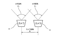
- FIG. 2 is a view of the camera unit of the obstacle detection apparatus as viewed from above.
- FIG. 3 is a side view of the camera unit of the obstacle detection apparatus.
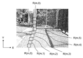
- FIG. 4 is a diagram illustrating an example of a left image (first image) of stereo images captured by the camera unit.
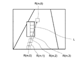
- FIG. 5 is a diagram illustrating an example of the right image (second image) of the stereo images.
- FIG. 6 is a flowchart for explaining the operation of the calculation unit of the obstacle detection apparatus.
- FIG. 7 is a diagram illustrating an example of a first image of a small obstacle.
- FIG. 8 is a diagram illustrating an example of a second image of a small obstacle.
- FIG. 7 is a diagram illustrating an example of a first image of a small obstacle.
- FIG. 10A is a schematic diagram illustrating a transfer order of image data captured by the camera unit of the obstacle detection apparatus according to the third embodiment of the present invention.
- FIG. 10B is a schematic diagram illustrating a transfer order of image data captured by the camera unit of the obstacle detection apparatus.
- FIG. 10C is a schematic diagram illustrating a transfer order of image data captured by the camera unit of the obstacle detection apparatus.
- FIG. 10D is a schematic diagram illustrating a transfer order of image data captured by the camera unit of the obstacle detection apparatus.
- FIG. 1 shows a block diagram of an obstacle detection apparatus according to a first embodiment of the present invention.
- the obstacle detection apparatus includes a camera unit 1 as an example of a stereo camera, a calculation unit 2, and an output device 3 that outputs a calculation result of the calculation unit 2.
- the camera unit 1 includes two cameras 11 and 12 that are arranged with a predetermined interval on the left and right sides and with the optical axes in parallel.
- the calculation unit 2 receives image data of stereo images captured by the two cameras 11 and 12 and is obtained by the parallax calculation unit 21 that obtains the parallax at each location in the stereo image and the parallax calculation unit 21.
- FIG. 2 is a diagram of the camera unit 1 of the obstacle detection device as viewed from above
- FIG. 3 is a diagram of the camera unit 1 of the obstacle detection device as viewed from the side.
- the two cameras 11 and 12 shown in FIGS. 2 and 3 are installed on the left and right of the front part of a senior car or an electric wheelchair (not shown).
- the interval between the optical axes of the left and right cameras 11 and 12 is defined as “camera interval W”.
- the height from the road surface on which the cameras 11 and 12 are mounted is defined as “mounting height H” (camera height), and the angle with respect to the horizontal plane when the cameras 11 and 12 are faced down is defined as “the depression angle ⁇ ”.
- the horizontal angle of view of the cameras 11 and 12 is ⁇ H and the vertical angle of view ⁇ V.
- the two cameras 11 and 12 are mounted apart from each other in the left and right directions, but they may be attached in the vertical and diagonal directions. In the following, an example in which the two cameras 11 and 12 are mounted apart from each other will be described.
- FIGS. 4 and 5 are examples of left and right images taken by two cameras 11 and 12 (shown in FIGS. 2 and 3). Since the cameras 11 and 12 are left and right, the images of the left camera 11 facing the subject and the right camera 12 facing the subject are different.
- the left image (first image) captured by the left camera 11 is divided into a plurality of blocks arranged in a matrix, and the image shown in each block is the right image (second image) captured by the right camera 12. )
- the first purpose is to find out where it is.
- the size of the block that divides the left image may be any size, but if it is too small, there is a high possibility that it will be mistaken for a different place, and accuracy will be reduced. On the other hand, if the size of the block is too large, a plurality of objects at different distances may appear in the block, which also causes a decrease in accuracy. In the case of an image size of 640 ⁇ 480, it is appropriate that the size is approximately 64 ⁇ 32 pixels or 32 ⁇ 32 pixels.
- the left image (first image) is divided into a plurality of blocks arranged in a matrix of N rows (N is an integer of 2 or more) ⁇ M columns (M is an integer of 2 or more).
- a rectangular area of the right image (second image) shown in FIG. 5 in which an object that is the same as or similar to the object shown in the block L (m, n) of the left image (first image) is shown is the corresponding block R ( m, n).
- the XY coordinates of the corresponding block of the right image (second image) shown in FIG. 5 are obtained with reference to the left image (first image) shown in FIG.
- the XY coordinates of the corresponding block may be obtained using the left image as the image and the second image.
- the horizontal direction of the first and second images is the X coordinate
- the vertical direction of the first and second images is the Y coordinate
- the XY coordinates representing the position of each block of the first and second images may be the coordinates of the center position of the rectangular block, the coordinates of the lower left corner of the rectangular block, or the like.
- FIG. 6 is a flowchart for explaining the operation of the processing of the calculation unit 2 shown in FIG. 1, and searches for the corresponding block of the right image (second image) corresponding to each block of the left image (first image). Find the parallax.
- the parallax calculation unit 21 sequentially executes the columns m of the left image (first image) in FIG.
- Step S2 (First step of parallax calculation step) Next, for the lowermost block L (m, 0) of the m columns of the left image (first image), the corresponding block R (m, 0) of the right image (second image) in which the same or similar object is shown. Search for 0).
- the Y coordinate of the corresponding block R (m, 0) is the block L ( It is the same as the Y coordinate of m, 0). Therefore, only the X coordinate of the corresponding block R (m, 0) needs to be obtained. For this, a block at the position of each X coordinate in the 0th row of the right image (second image) is cut out and compared with the block L (m, 0), and the right image (second image) with the most similar image is extracted. Find the corresponding block.
- Step S4 (Second step of parallax calculation step) Next, the corresponding block R (m, n) corresponding to the block L (m, n) is searched in the X coordinate setting range with the X coordinate of the corresponding block R (m, 0) as the center.
- the Y coordinate of the corresponding block R (m, n) is the same as the Y coordinate of the block L (m, n). Further, as the X coordinate of the corresponding block R (m, n), the vicinity of the X coordinate of the corresponding block R (m, n ⁇ 1) obtained in step S1 may be searched. A predetermined X coordinate setting range centering on the X coordinate of the corresponding block R (m, n-1) corresponding to the block L (m, n-1) is searched.
- the lower part of the left and right images is near a senior car or an electric wheelchair, so the road surface (including the floor surface) is shown, but the distance to the road surface changes continuously, so the corresponding block R (m, 0)
- the X coordinate of the corresponding block R (m, 1) does not change greatly. Therefore, in the case of an image of 640 ⁇ 480 pixels, for example, it is sufficient to search for a range of ⁇ 16 pixels.
- Step S6 Increment n and return to step S4 to repeat steps S4 and S5.
- Step S8 Increment m and return to step S2, and repeat steps S2 to S8.
- Step S9 (Third step of the parallax calculation step)
- the parallax of each block of the left and right images (first and second images) is obtained as the difference between the X coordinate of L (m, n) and the X coordinate of R (m, n).
- the relationship between the parallax of the object and the distance to the object is a simple proportional relationship, and the proportionality coefficient is obtained from the angle of view of the camera and the number of pixels, but it is proportional by actually measuring the relationship between the parallax of the object and the distance to the object. A coefficient may be obtained.
- Step S10 (obstacle detection step) Then, based on the parallax of each block of the left and right images (first and second images) obtained by the parallax calculation unit 21 in step S9, the obstacle detection unit 22 obtains the distance to the object, and the object is obstructed. Whether it is an object is detected.
- processing is performed for each column, but processing is performed for each row, such as processing all of the lower row and then processing the upper row in order. You may do.
- the parallax calculation unit 21 first uses the same Y coordinate as the Y coordinate of the block for the bottom block of the left image (first image), In addition, the corresponding block in the second image in which an object that is the same as or similar to the object in the block is reflected is searched, and then the searched block in the left image (first image) is sequentially shifted to the upper block.
- the Y coordinate is the same as the Y coordinate of the block of the left image (first image) image.
- the obstacle detection apparatus of 2nd Embodiment of this invention has the same structure as the obstacle detection apparatus of 1st Embodiment except the operation
- step S2 shown in FIG. 6 of the first embodiment the corresponding block R (m, 0) is searched for all X coordinates of the right image (second image).
- the approximate parallax is obtained from the mounting depression angle and height of the cameras 11 and 12 and the vertical angle of view, and the vicinity thereof is searched.
- the parallax of the left and right images (first and second images) is obtained, and the vicinity of the coordinates obtained by subtracting the parallax from the X coordinate of the block L (m, 0). If the X coordinate setting range (for example, ⁇ 16 pixels) is searched, the coordinates of the corresponding block R (m, 0) can be obtained in a short time.
- the obstacle detection device of the second embodiment has the same effect as the obstacle detection device of the first embodiment.
- the obstacle detection device of the third embodiment of the present invention has the same configuration as the obstacle detection device of the first embodiment except for the mounting direction of the cameras 11 and 12 and the operation of the parallax calculation unit 21.
- FIG. 1 is incorporated.
- the mounting directions of the cameras 11 and 12 are changed, but the arrangement direction of the cameras 11 and 12 is not changed in the horizontal direction.
- a normal camera is configured to transfer data from the top left to the bottom line one line at a time from the top left to the top right as shown in FIG. 10A.
- the parallax calculation process is sequentially performed from the block in the lower row as in the obstacle detection device of the first embodiment, the process is started only after all the images on one screen are stored in the memory. I can't.
- the image data is transferred from the cameras 11 and 12 to the parallax calculation unit 21 in order from the lower right to the lower left of the screen, and from the lower to the upper.
- the parallax calculation process can be started in order.
- the right image (second image) is sequentially transferred according to the transfer of the image data.
- the corresponding block of the image) can be searched, and the obstacle detection time can be shortened.
- FIG. 10C when the cameras 11 and 12 are rotated 90 degrees counterclockwise and attached, data can be transferred one column at a time from the left to the right of the image.
- FIG. 10D when the cameras 11 and 12 are rotated 90 degrees in the clockwise direction and attached, data can be transferred one column at a time from the right to the left of the image. In this case, the processing can be started as soon as the image data of one column of the left or right column is completed.
- the left and right images are transferred from the cameras 11 and 12 to the parallax calculation unit 21 one column at a time from the right column to the left, or one column from the left column to the right.
- the corresponding block of the right image (second image) can be searched sequentially according to the transfer of the image data, and the obstacle detection time can be shortened.
- the obstacle detection device of the third embodiment has the same effect as the obstacle detection device of the first embodiment.
- the obstacle detection device used for the senior car and the electric wheelchair has been described.
- the obstacle detection device may be applied to other moving means such as a transport vehicle.
- the obstacle detection device of this invention Stereo camera (11, 12), A parallax calculation unit 21 for obtaining parallax of an object appearing in the first and second images based on the first image and the second image captured by the stereo camera (11, 12); An obstacle detection unit 22 for obtaining a distance to the object based on the parallax of the object shown in the first and second images obtained by the parallax calculation unit 21 and detecting whether the object is an obstacle;
- the horizontal direction of the first and second images is the X coordinate
- the vertical direction of the first and second images is the Y coordinate
- the first image is divided into a plurality of blocks arranged in a matrix
- the parallax calculation unit 21 Correspondence in the second image in which the same or similar object to the block in the bottom row of the first image has the same Y coordinate as the block and the same or similar object is reflected in the block Explore the block, Next, when searching for a corresponding block in the second image in which an object that is the same as or similar to the block is sequentially
- a plurality of blocks arranged in the horizontal direction are set as one row, and a plurality of blocks arranged in the vertical direction are set as one column.
- the process of finding an obstacle can be simplified, the processing time can be shortened, and the hardware configuration can be simplified.
- the parallax calculation unit 21 Based on the vertical angle of view, depression angle and camera height of the stereo camera, calculate the distance to the road surface shown in the bottom row block of the first image, Based on the distance to the road surface that appears in the bottom row block of the first image, the parallax between the road surface that appears in the bottom row block of the first image and the road surface that may appear in the second image To calculate The block of the first image in the X coordinate setting range having the same Y coordinate as the Y coordinate of the block in the bottom row of the first image and centering on the X coordinate obtained by subtracting the parallax from the X coordinate of the block The corresponding block in the second image in which the same or similar object is reflected is searched.
- the parallax between the road surface that appears in the bottom block of one image and the road surface that would appear in the second image can be easily calculated, and an obstacle can be detected in a shorter time.
- the first and second image data are transferred from the stereo camera (11, 12) to the parallax calculation unit 21 line by line from the bottom line to the top,
- the parallax calculation unit 21 The same or similar to the object shown in the block of the first image when the image data included in the block of one row of the first image and the image data of the second image corresponding to the image data are aligned.
- the corresponding block of the second image in which the object is reflected is searched.
- the first and second image data are transferred from the stereo camera (11, 12) to the parallax calculation unit 21 line by line from the bottom line to the top, according to the transfer of the image data.
- the corresponding block of the second image can be searched sequentially, and the obstacle detection time can be shortened.
- the first and second image data are transferred from the stereo camera (11, 12) to the parallax calculation unit 21 one column from the right column to the left, or one column from the left column to the right.
- the parallax calculation unit 21 When the image data included in the plurality of blocks of the first image and the image data of the second image corresponding to the image data are aligned, the same or similar to the object shown in the block of the first image The corresponding block of the second image in which the object is reflected is searched.
- the first and second image data from the stereo camera (11, 12) to the parallax calculation unit 21 one column from the right column to the left, or from the left column to the right.
- the corresponding block of the second image can be searched sequentially according to the transfer of the image data, and the obstacle detection time can be reduced.
- a parallax calculation step in which the parallax calculation unit 21 obtains the parallax of the object shown in the first and second images based on the two first and second images having parallax photographed by the stereo camera (11, 12); , Based on the parallax of the object shown in the first and second images obtained in the parallax calculation step, the distance to the object is obtained, and the obstacle detection unit 22 detects whether the object is an obstacle.
- An obstacle detection method comprising the steps of:
- the horizontal direction of the first and second images is the X coordinate
- the vertical direction of the first and second images is the Y coordinate
- the first image is divided into a plurality of blocks arranged in a matrix
- the parallax calculation step includes Correspondence in the second image in which the same or similar object to the block in the bottom row of the first image has the same Y coordinate as the block and the same or similar object is reflected in the block
- a first step of searching for blocks Next, when searching for a corresponding block in the second image in which an object that is the same as or similar to the block is sequentially searched from the searched block of the first image, the first image In the X coordinate setting range centered on the X coordinate of the corresponding block of the second image corresponding to the searched block immediately below the block of the first image and the same Y coordinate as the Y coordinate of the block of
- the process of finding an obstacle can be simplified, the processing time can be shortened, and the hardware configuration can be simplified.
Landscapes
- Engineering & Computer Science (AREA)
- Physics & Mathematics (AREA)
- General Physics & Mathematics (AREA)
- Theoretical Computer Science (AREA)
- Multimedia (AREA)
- Computer Vision & Pattern Recognition (AREA)
- Software Systems (AREA)
- Electromagnetism (AREA)
- Radar, Positioning & Navigation (AREA)
- Remote Sensing (AREA)
- Artificial Intelligence (AREA)
- Computing Systems (AREA)
- Databases & Information Systems (AREA)
- Evolutionary Computation (AREA)
- General Health & Medical Sciences (AREA)
- Medical Informatics (AREA)
- Health & Medical Sciences (AREA)
- Measurement Of Optical Distance (AREA)
- Image Analysis (AREA)
- Image Processing (AREA)
- Traffic Control Systems (AREA)
Abstract
視差演算部によって、まず、第1画像の最下行のブロックに対して、そのブロックのY座標と同じY座標で、かつ、そのブロックに写っている物体と同一または類似の物体が写っている第2画像中の対応ブロックを探索し(S2)、次に、第1画像の探索済みブロックから順次上のブロックに対して、そのブロックと同一または類似の物体が写っている第2画像中の対応ブロックを探索するときに、第1画像像のブロックのY座標と同じY座標で、かつ、第1画像のブロックの直下の探索済みブロックに対応する第2画像の対応ブロックのX座標を中心とするX座標設定範囲において、第1画像のブロックと同一または類似の物体が写っている第2画像中の対応ブロックを探索する(S4)。これにより、障害物を見つける処理を簡略化でき、処理時間を短縮できると共に、ハードウェア構成を簡略化できる障害物検出装置を提供する。
Description
この発明は、障害物検出装置および障害物検出方法に関し、詳しくは、ステレオカメラを用いて撮像した画像から路面の凹凸や障害物を検出する障害物検出装置および障害物検出方法に関する。
最近では、自動車に搭載したカメラ等により車外の対象風景を撮像し、この撮像した画像を画像処理して自動車から対象物までの距離を求める計測技術が有力な手段として採用されるようになった(例えば、特開平5-114099号公報(特許文献1)参照)。
この画像による距離計測技術は、単眼視像からカメラ位置との関係を用いて対象物までの距離を推定する技術と、複数のカメラにより撮影した複数画像から、三角測量の原理を用いて対象物までの距離を求める技術とに大別される。
このうち、複数の画像から三角測量の原理を用いて距離を求める計測技術は、左右画像における同一物体の位置の相対的なずれから距離を求めるので、正確な距離を求めることができる。
このような画像による距離計測技術を用いて自動車から対象物までの距離を求め、前方車両やガードレールなどとの衝突の危険を予測して、車両にブレーキをかけるなどの制御を行う方法が実用化されている。
一方、法令で定められた制限の元で歩行者と看做される車両として、シニアカーや電動車椅子があり、社会の高齢化に伴い、今後走行台数の増加が予測される。これらのシニアカーや電動車椅子は、運転者が高齢であったり、障害を持っていたりするという点で、より安全に配慮されたものでなければならない。したがって、シニアカー用や電動車椅子用に、自動車用にあるようなカメラを用いた危険予測を行う方法の開発が急務である。
上記電動車椅子では、ガードレールや壁などの障害物に衝突するのはもちろん、路面の小さな段差で転倒したりする事故が報告されており、それを防止するためには、前方の障害物だけではなく、路面の小さな障害物や段差も検出する必要がある。
上記画像による距離計測技術では、ステレオカメラで障害物までの距離を求める場合、左画像に写っている障害物が右画像のどこに写っているかを探索し、左右画像に写っている座標の差から視差を求め、その視差から距離を算出する。ここで、路面上にある5cmほどの大きさの障害物を判別するためには、最低でも640×480ピクセルの画素数のカメラが必要である。この画素数のステレオカメラで2m先の障害物を撮影した場合、その障害物の左右カメラでの視差は約60ピクセルとなるため、障害物が写った左画像のブロックに対して、右画像で最低でも視差が0~60ピクセルの位置を探索して同一の障害物が写っているブロックを探さねばならない。障害物がより近くにある場合は、視差が大きくなるため、さらに広い範囲を探索せねばならず、処理時間やハードウェア規模が大きくなってしまう。
そこで、この発明の課題は、障害物を見つける処理を簡略化でき、処理時間を短縮できると共に、ハードウェア構成を簡略化できる障害物検出装置および障害物検出方法を提供することにある。
上記課題を解決するため、この発明の障害物検出装置は、
ステレオカメラと、
上記ステレオカメラで撮影された第1画像と第2画像に基づいて、上記第1,第2画像に写る物体の視差を求める視差演算部と、
上記視差演算部により求めた上記第1,第2画像に写る物体の視差に基づいて、上記物体までの距離を求めて、上記物体が障害物か否かを検出する障害物検出部と
を備え、
上記第1,第2画像の横方向をX座標とし、上記第1,第2画像の縦方向をY座標とすると共に、上記第1画像をマトリックス状に配列された複数のブロックに分割し、
上記視差演算部は、
上記第1画像の最下行のブロックに対して、そのブロックのY座標と同じY座標で、かつ、そのブロックに写っている物体と同一または類似の物体が写っている上記第2画像中の対応ブロックを探索し、
次に、上記第1画像の探索済みブロックから順次上のブロックに対して、そのブロックと同一または類似の物体が写っている上記第2画像中の対応ブロックを探索するときに、上記第1画像のブロックのY座標と同じY座標で、かつ、上記第1画像のブロックの直下の探索済みブロックに対応する上記第2画像の対応ブロックのX座標を中心とするX座標設定範囲において、上記第1画像のブロックと同一または類似の物体が写っている上記第2画像中の対応ブロックを探索して、
上記第1画像のブロックのX座標とそのブロックに対応する上記第2画像の対応ブロックのX座標との差から上記第1,第2画像に写る物体の視差を求めることを特徴とする。
ステレオカメラと、
上記ステレオカメラで撮影された第1画像と第2画像に基づいて、上記第1,第2画像に写る物体の視差を求める視差演算部と、
上記視差演算部により求めた上記第1,第2画像に写る物体の視差に基づいて、上記物体までの距離を求めて、上記物体が障害物か否かを検出する障害物検出部と
を備え、
上記第1,第2画像の横方向をX座標とし、上記第1,第2画像の縦方向をY座標とすると共に、上記第1画像をマトリックス状に配列された複数のブロックに分割し、
上記視差演算部は、
上記第1画像の最下行のブロックに対して、そのブロックのY座標と同じY座標で、かつ、そのブロックに写っている物体と同一または類似の物体が写っている上記第2画像中の対応ブロックを探索し、
次に、上記第1画像の探索済みブロックから順次上のブロックに対して、そのブロックと同一または類似の物体が写っている上記第2画像中の対応ブロックを探索するときに、上記第1画像のブロックのY座標と同じY座標で、かつ、上記第1画像のブロックの直下の探索済みブロックに対応する上記第2画像の対応ブロックのX座標を中心とするX座標設定範囲において、上記第1画像のブロックと同一または類似の物体が写っている上記第2画像中の対応ブロックを探索して、
上記第1画像のブロックのX座標とそのブロックに対応する上記第2画像の対応ブロックのX座標との差から上記第1,第2画像に写る物体の視差を求めることを特徴とする。
ここで、第1画像のマトリックス状に配列された複数のブロックは、横方向に並んだ複数のブロックを1行とし、縦方向に並んだ複数のブロックを1列とする。
また、一実施形態の障害物検出装置では、
上記視差演算部は、
上記ステレオカメラの垂直画角,俯角およびカメラ高さに基づいて、上記第1画像の最下行のブロックに写っている路面までの距離を算出し、
上記第1画像の最下行のブロックに写る上記路面までの距離に基づいて、上記第1画像の最下行のブロックに写る上記路面と上記第2画像に写っているであろう上記路面との視差を算出して、
上記第1画像の最下行のブロックのY座標と同じY座標で、かつ、そのブロックのX座標から上記視差を減算したX座標を中心とする上記X座標設定範囲において、上記第1画像のブロックと同一または類似の物体が写っている上記第2画像中の対応ブロックを探索する。
上記視差演算部は、
上記ステレオカメラの垂直画角,俯角およびカメラ高さに基づいて、上記第1画像の最下行のブロックに写っている路面までの距離を算出し、
上記第1画像の最下行のブロックに写る上記路面までの距離に基づいて、上記第1画像の最下行のブロックに写る上記路面と上記第2画像に写っているであろう上記路面との視差を算出して、
上記第1画像の最下行のブロックのY座標と同じY座標で、かつ、そのブロックのX座標から上記視差を減算したX座標を中心とする上記X座標設定範囲において、上記第1画像のブロックと同一または類似の物体が写っている上記第2画像中の対応ブロックを探索する。
また、一実施形態の障害物検出装置では、
上記ステレオカメラから上記視差演算部に上記第1,第2画像データが下の行から上に向かって1行ずつ転送され、
上記視差演算部は、
上記第1画像の1行のブロックに含まれる画像データとその画像データに対応する上記第2画像の画像データとが揃った時点で、上記第1画像のブロックに写っている物体と同一または類似の物体が写っている上記第2画像の対応ブロックを探索する。
上記ステレオカメラから上記視差演算部に上記第1,第2画像データが下の行から上に向かって1行ずつ転送され、
上記視差演算部は、
上記第1画像の1行のブロックに含まれる画像データとその画像データに対応する上記第2画像の画像データとが揃った時点で、上記第1画像のブロックに写っている物体と同一または類似の物体が写っている上記第2画像の対応ブロックを探索する。
また、一実施形態の障害物検出装置では、
上記ステレオカメラから上記視差演算部に上記第1,第2画像データが右の列から左に向かって1列ずつ、または、左の列から右に向かって1列ずつ転送され、
上記視差演算部は、
上記第1画像の複数列のブロックに含まれる画像データとその画像データに対応する上記第2画像の画像データとが揃った時点で、上記第1画像のブロックに写っている物体と同一または類似の物体が写っている上記第2画像の対応ブロックを探索する。
上記ステレオカメラから上記視差演算部に上記第1,第2画像データが右の列から左に向かって1列ずつ、または、左の列から右に向かって1列ずつ転送され、
上記視差演算部は、
上記第1画像の複数列のブロックに含まれる画像データとその画像データに対応する上記第2画像の画像データとが揃った時点で、上記第1画像のブロックに写っている物体と同一または類似の物体が写っている上記第2画像の対応ブロックを探索する。
また、この発明の障害物検出方法では、
ステレオカメラで撮影された第1画像と第2画像に基づいて、上記第1,第2画像に写る物体の視差を視差演算部により求める視差演算ステップと、
上記視差演算ステップで求めた上記第1,第2画像に写る物体の視差に基づいて、上記物体までの距離を求めて、上記物体が障害物か否かを障害物検出部により検出する障害物検出ステップと
を有する障害物検出方法であって、
上記第1,第2画像の横方向をX座標とし、上記第1,第2画像の縦方向をY座標とすると共に、上記第1画像をマトリックス状に配列された複数のブロックに分割し、
上記視差演算ステップは、
上記第1画像の最下行のブロックに対して、そのブロックのY座標と同じY座標で、かつ、そのブロックに写っている物体と同一または類似の物体が写っている上記第2画像中の対応ブロックを探索する第1のステップと、
次に、上記第1画像の探索済みブロックから順次上のブロックに対して、そのブロックと同一または類似の物体が写っている上記第2画像中の対応ブロックを探索するときに、上記第1画像のブロックのY座標と同じY座標で、かつ、上記第1画像のブロックの直下の探索済みブロックに対応する上記第2画像の対応ブロックのX座標を中心とするX座標設定範囲において、上記第1画像のブロックと同一または類似の物体が写っている上記第2画像中の対応ブロックを探索する第2のステップと、
上記第1,第2のステップで得られた上記第1画像のブロックのX座標とそのブロックに対応する上記第2画像の対応ブロックのX座標との差から上記第1,第2画像に写る物体の視差を求める第3のステップと
を有することを特徴とする。
ステレオカメラで撮影された第1画像と第2画像に基づいて、上記第1,第2画像に写る物体の視差を視差演算部により求める視差演算ステップと、
上記視差演算ステップで求めた上記第1,第2画像に写る物体の視差に基づいて、上記物体までの距離を求めて、上記物体が障害物か否かを障害物検出部により検出する障害物検出ステップと
を有する障害物検出方法であって、
上記第1,第2画像の横方向をX座標とし、上記第1,第2画像の縦方向をY座標とすると共に、上記第1画像をマトリックス状に配列された複数のブロックに分割し、
上記視差演算ステップは、
上記第1画像の最下行のブロックに対して、そのブロックのY座標と同じY座標で、かつ、そのブロックに写っている物体と同一または類似の物体が写っている上記第2画像中の対応ブロックを探索する第1のステップと、
次に、上記第1画像の探索済みブロックから順次上のブロックに対して、そのブロックと同一または類似の物体が写っている上記第2画像中の対応ブロックを探索するときに、上記第1画像のブロックのY座標と同じY座標で、かつ、上記第1画像のブロックの直下の探索済みブロックに対応する上記第2画像の対応ブロックのX座標を中心とするX座標設定範囲において、上記第1画像のブロックと同一または類似の物体が写っている上記第2画像中の対応ブロックを探索する第2のステップと、
上記第1,第2のステップで得られた上記第1画像のブロックのX座標とそのブロックに対応する上記第2画像の対応ブロックのX座標との差から上記第1,第2画像に写る物体の視差を求める第3のステップと
を有することを特徴とする。
以上より明らかなように、この発明によれば、視差演算部によって、まず、第1画像の最下行のブロックに対して、そのブロックのY座標と同じY座標で、かつ、そのブロックに写っている物体と同一または類似の物体が写っている第2画像中の対応ブロックを探索し、次に、第1画像の探索済みブロックから順次上のブロックに対して、そのブロックに同一または類似の物体が写っている第2画像中の対応ブロックを探索するときに、第1画像のブロックのY座標と同じY座標で、かつ、第1画像のブロックの直下の探索済みブロックに対応する第2画像の対応ブロックのX座標を中心とするX座標設定範囲において、第1画像のブロックと同一または類似の物体が写っている第2画像中の対応ブロックを探索することによって、狭い範囲を探索するだけで視差が大きい場所にある障害物を見つけることができるため、障害物を見つけるときの処理時間が短くなると共に、探索処理を行うハードウェアの規模も小さくなる。
以下、この発明の障害物検出装置および障害物検出方法を図示の実施の形態により詳細に説明する。
〔第1実施形態〕
図1はこの発明の第1実施形態の障害物検出装置のブロック図を示している。
図1はこの発明の第1実施形態の障害物検出装置のブロック図を示している。
この第1実施形態の障害物検出装置は、図1に示すように、ステレオカメラの一例としてのカメラ部1と、演算部2と、演算部2の演算結果を出力する出力装置3とを備えている。カメラ部1は、左右に所定の間隔をあけて光軸を平行にして配置された2つのカメラ11,12を有する。また、演算部2は、2つのカメラ11,12で撮影されたステレオ画像の画像データが入力され、ステレオ画像中の各箇所の視差を求める視差演算部21と、視差演算部21により得られた視差に基づいて障害物や段差を検出する障害物検出部22を有する。上記障害物検出部22は、視差に基づいて算出した距離が一定距離以下になると、障害物があると判断する。
図2は上記障害物検出装置のカメラ部1を上方から見た図であり、図3は上記障害物検出装置のカメラ部1を側方から見た図である。
図2,図3に示す2つのカメラ11,12は、図示しないシニアカーや電動車椅子の前方部の左右に設置する。左右のカメラ11,12の光軸の間隔を「カメラ間隔W」とする。カメラ11,12を取付けた路面からの高さを「取付高H」(カメラ高さ)とし、カメラ11,12を下向きにつけた場合の水平面に対する角度を「俯角β」とする。また、カメラ11,12の水平画角をθHとし、垂直画角θVとする。
カメラ11,12の「水平画角θH」や「垂直画角θV」が大きすぎると、障害物や段差が小さく写ってしまうため、精度が悪くなるが、逆に「水平画角θH」や「垂直画角θV」が小さすぎると、障害物や段差を検出できる範囲が狭くなるため、適切に設定する必要がある。また、「俯角β」はシニアカーや電動車椅子の近くが視野に入るように設定する。
図2,図3では、2つのカメラ11,12を左右に離して取付けているが、上下や斜め方向に離して取付けてもかまわない。以降では、2つのカメラ11,12は左右に離して取付けている例について説明するが、上下や斜めでも基本的には同じである。
図4,図5は2つのカメラ11,12(図2,図3に示す)で撮影された左右画像の一例である。カメラ11,12が左右に離れているため、被写体に向かって左側のカメラ11と被写体に向かって右側のカメラ12の画像は異なっている。左側のカメラ11で撮像した左画像(第1画像)をマトリックス状に配列された複数のブロックに分割し、各ブロックに写っている画像が、右側のカメラ12で撮像した右画像(第2画像)のどこに写っているかを求めるのが第一の目的となる。
上記左画像(第1画像)を分割するブロックの大きさは、任意の大きさでかまわないが、小さすぎると似た異なる場所と間違えてしまう可能性が大きくなり、精度が落ちてしまう。逆に、ブロックの大きさが大きすぎると、ブロック内に異なる距離にある複数の物体が写ってしまう場合があり、こちらも精度が落ちる原因となる。640×480の画像サイズの場合、およそ64×32ピクセルや32×32ピクセルとするのが適切である。
ここで、左画像(第1画像)は、N行(Nは2以上の整数)×M列(Mは2以上の整数)のマトリックス状に配列された複数のブロックに分割される。
図4,図5のとおり、図4に示す左画像(第1画像)は左下のブロックをL(0,0)とし、右にm個(m=0,1,2,…,M)、上にn個(n=0,1,2,…,N)の位置のブロックをブロックL(m,n)とする。この左画像(第1画像)のブロックL(m,n)に写っている物体と同一または類似の物体が写っている図5に示す右画像(第2画像)の矩形領域を対応ブロックR(m,n)とする。
この実施の形態では、図4に示す左画像(第1画像)を基準として図5に示す右画像(第2画像)の対応ブロックのXY座標を求めるが、逆に右画像を基準の第1画像として左画像を第2画像として対応ブロックのXY座標を求めてもよい。
なお、上記第1,第2画像の横方向をX座標とし、第1,第2画像の縦方向をY座標とする。また、第1,第2画像の各ブロックの位置を表すXY座標は、矩形のブロックの中心位置の座標でもよいし、矩形のブロックの左下の角部の座標などでもよい。
そして、図4,図5示す左右一対の画像(ステレオ画像)が図1に示す演算部2に送られる。
図6は図1に示す演算部2の処理の動作を説明するためのフローチャートであり、左画像(第1画像)の各ブロックに対応する右画像(第2画像)の対応ブロックを探索して視差を求める。ここで、視差演算部21は、ステップS1~S9で図4の左画像(第1画像)の各列mが0からMについて順に実行する。
〔ステップS1〕
m=0とする。
m=0とする。
〔ステップS2〕 (視差演算ステップの第1のステップ)
次に、左画像(第1画像)のm列の一番下のブロックL(m,0)について、同一または類似の物体が写っている右画像(第2画像)の対応ブロックR(m,0)を探索する。
次に、左画像(第1画像)のm列の一番下のブロックL(m,0)について、同一または類似の物体が写っている右画像(第2画像)の対応ブロックR(m,0)を探索する。
ここで、ステレオカメラ(カメラ11,12)で撮影した左右画像(第1,第2画像)は、左右方向にのみずれているため、対応ブロックR(m,0)のY座標はブロックL(m,0)のY座標と同じである。よって、対応ブロックR(m,0)のX座標のみを求めればよい。これには、右画像(第2画像)の0行の各X座標の位置のブロックを切り出し、ブロックL(m,0)と比較し、画像が最も似ている右画像(第2画像)の対応ブロックを見つける。
左画像(第1画像)と右画像(第2画像)のブロックの比較は、左右ブロック内の各点について、ピクセル値を比較し、その絶対値の和を取る方法などがあるが、どのような方法を用いてもよい。
〔ステップS3〕
次に、n=1とする。
次に、n=1とする。
〔ステップS4〕 (視差演算ステップの第2のステップ)
次に、ブロックL(m,n)に対応する対応ブロックR(m,n)を対応ブロックR(m,0)のX座標を中心としてX座標設定範囲で探索する。
次に、ブロックL(m,n)に対応する対応ブロックR(m,n)を対応ブロックR(m,0)のX座標を中心としてX座標設定範囲で探索する。
このとき、対応ブロックR(m,n)のY座標はブロックL(m,n)のY座標と同じである。また、対応ブロックR(m,n)のX座標としては、ステップS1で求めた対応ブロックR(m,n-1)のX座標の近辺を探索すればよく、この実施形態では、探索済みのブロックL(m,n-1)に対応する対応ブロックR(m,n-1)のX座標を中心とする所定のX座標設定範囲を探索する。
左右画像の下部はシニアカーや電動車椅子の近くであるため、路面(床面などを含む)が写っているが、路面への距離は連続的に変化するため、対応ブロックR(m,0)と対応ブロックR(m,1)のX座標は大きく変化しない。よって、640×480ピクセルの画像の場合、例えば、±16ピクセルの範囲を探索すれば十分である。
また、図5では、対応ブロックR(m,0)から対応ブロックR(m,4)までは路面が写っているため、X座標が徐々に変化している。対応ブロックR(m,5)より上は障害物が写っているが、障害物が路面と接する位置では、障害物の視差は路面の視差と等しいので、障害物の左右画像(第1,第2画像)での視差が大きくても小さくても限定された範囲を探索するだけで視差を求めることが可能となる。
〔ステップS5〕
m列について、一番上まで繰り返したか否かを判定する(n=Nか否かを判定)。そして、一番上まで繰り返していない(n<N)と判定すると、ステップS6に進む一方、一番上まで繰り返した(n=N)と判定すると、ステップS7に進む。
m列について、一番上まで繰り返したか否かを判定する(n=Nか否かを判定)。そして、一番上まで繰り返していない(n<N)と判定すると、ステップS6に進む一方、一番上まで繰り返した(n=N)と判定すると、ステップS7に進む。
〔ステップS6〕
nをインクリメントしてステップS4に戻り、ステップS4,S5を繰り返す。
〔ステップS7〕
全ての列で繰り返したか否かを判定する(m=Mか否かを判定)。そして、全ての列で繰り返していない(m<M)と判定すると、ステップS8に進む一方、全ての列で繰り返した(m=M)と判定すると、この処理を終了する。
nをインクリメントしてステップS4に戻り、ステップS4,S5を繰り返す。
〔ステップS7〕
全ての列で繰り返したか否かを判定する(m=Mか否かを判定)。そして、全ての列で繰り返していない(m<M)と判定すると、ステップS8に進む一方、全ての列で繰り返した(m=M)と判定すると、この処理を終了する。
〔ステップS8〕
mをインクリメントしてステップS2に戻り、ステップS2~S8を繰り返す。
mをインクリメントしてステップS2に戻り、ステップS2~S8を繰り返す。
以上で、左画像(第1画像)の各ブロックL(m,n)について、対応する右画像(第2画像)の対応ブロックR(m,n)のXY座標がわかる。
〔ステップS9〕 (視差演算ステップの第3のステップ)
次に、左右画像(第1,第2画像)の各ブロックの視差を演算する。この左右画像(第1,第2画像)各ブロックの視差は、L(m,n)のX座標とR(m,n)のX座標の差として求まる。物体の視差と物体への距離の関係は、単純な比例関係であり、比例係数は、カメラの画角とピクセル数から求まるが、物体の視差と物体への距離の関係を実測して、比例係数を求めてもよい。
次に、左右画像(第1,第2画像)の各ブロックの視差を演算する。この左右画像(第1,第2画像)各ブロックの視差は、L(m,n)のX座標とR(m,n)のX座標の差として求まる。物体の視差と物体への距離の関係は、単純な比例関係であり、比例係数は、カメラの画角とピクセル数から求まるが、物体の視差と物体への距離の関係を実測して、比例係数を求めてもよい。
〔ステップS10〕 (障害物検出ステップ)
そして、ステップS9で視差演算部21により求めた左右画像(第1,第2画像)の各ブロックの視差に基づいて、障害物検出部22によって、物体までの距離を求めて、その物体が障害物か否かを検出する。
そして、ステップS9で視差演算部21により求めた左右画像(第1,第2画像)の各ブロックの視差に基づいて、障害物検出部22によって、物体までの距離を求めて、その物体が障害物か否かを検出する。
図6のフローチャートに示す障害物検出方法では、1列ずつ処理を行うようにしているが、下の1行を全部処理し、次に上の行を順に処理するというように、1行ずつ処理をしてもよい。
図7,図8に示すような背の低い障害物がある場合、図7に示す左画像(第1画像)の障害物の上のブロックL(m,8)に対応する図8に示す右画像(第2画像)の対応ブロックR(m,8)を探索するとき、ブロックL(m,7)のX座標と同じX座標の近傍を探しても対応する場所が見つからない場合がある。このときは、手前側にすでに障害物が見つかっているので、それより奥側の障害物を検出する必要は特にないので、探索を打ち切ってもよい。
しかしながら、もし正しく対応ブロックR(m,8)を見つけたい場合には、R(m,8)が路面であるならば、同じく路面である対応ブロックR(m,0)~R(m,4)のX座標の延長線L上を探索すれば正しい対応ブロックR(m,8)を見つけることができる。対応ブロックR(m,0)~R(m,4)が路面かどうかは、それらのX座標が一定の傾きの直線上であれば路面上であると推定できる。
上記構成の障害物検出装置および障害物検出方法よれば、視差演算部21によって、まず、左画像(第1画像)の最下行のブロックに対して、そのブロックのY座標と同じY座標で、かつ、そのブロックに写っている物体と同一または類似の物体が写っている第2画像中の対応ブロックを探索し、次に、左画像(第1画像)の探索済みブロックから順次上のブロックに対して、そのブロックに同一または類似の物体が写っている右画像(第2画像)中の対応ブロックを探索するときに、左画像(第1画像)像のブロックのY座標と同じY座標で、かつ、左画像(第1画像)のブロックの直下の探索済みブロックに対応する右画像(第2画像)の対応ブロックのX座標を中心とするX座標設定範囲において、左画像(第1画像)のブロックと同一または類似の物体が写っている右画像(第2画像)中の対応ブロックを探索することによって、障害物を見つける処理を簡略化でき、処理時間の短縮化とハードウェア構成の簡略化ができる。
〔第2実施形態〕
また、この発明の第2実施形態の障害物検出装置は、視差演算部21の動作を除いて第1実施形態の障害物検出装置と同一の構成をしており、図1を援用する。
また、この発明の第2実施形態の障害物検出装置は、視差演算部21の動作を除いて第1実施形態の障害物検出装置と同一の構成をしており、図1を援用する。
上記第1実施形態の図6に示すステップS2では、対応ブロックR(m,0)は右画像(第2画像)の全X座標について探索したが、この第2実施形態の障害物検出装置では、カメラ11,12の取り付け俯角と高さと垂直画角からおおよその視差を求め、その付近を探索する。
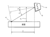
詳しくは、図9に示すように、カメラ11,12の垂直画角の半分をθ、カメラ11,12の俯角をβ、カメラ高さをhcとすると、画面の一番下に写っている路面(点P)までの距離dは、
d = hc / sin(β+θ)
で表される。
d = hc / sin(β+θ)
で表される。
そして、上記路面(点P)までの距離dに基づいて、左右画像(第1,第2画像)の視差を求め、ブロックL(m,0)のX座標から視差を差し引いた座標の付近のX座標設定範囲(例えば±16ピクセル)を探索すれば、短時間で対応ブロックR(m,0)の座標を求めることができる。
上記第2実施形態の障害物検出装置は、第1実施形態の障害物検出装置と同様の効果を有する。
〔第3実施形態〕
また、この発明の第3実施形態の障害物検出装置は、カメラ11,12の取付向きと視差演算部21の動作を除いて第1実施形態の障害物検出装置と同一の構成をしており、図1を援用する。
また、この発明の第3実施形態の障害物検出装置は、カメラ11,12の取付向きと視差演算部21の動作を除いて第1実施形態の障害物検出装置と同一の構成をしており、図1を援用する。
この第3実施形態の障害物検出装置では、カメラ11,12の夫々の取付向きを変えるが、カメラ11,12の配置方向は横方向で変わらない。
通常のカメラは、図10Aのように画面の左上端から右上端の1行ずつ、上から下の行に向けてデータを転送するようになっている。
したがって、上記第1実施形態の障害物検出装置のように、下の行のブロックから順に視差演算の処理を行う場合には、1画面全ての画像をメモリに記憶してからしか処理を開始することができない。
これに対して、この第3実施形態の障害物検出装置では、カメラ11,12の夫々を光軸に対して直角な平面に沿って時計方向に180度回転させて取り付けると、図10Bのように、まず画面の右下から左下の1行、下から上に向かって順に1行ずつ画像データがカメラ11,12から視差演算部21に転送される。これにより、左右画像(第1,第2画像)の下の行のブロックの画像データが揃い次第、順に視差演算の処理を開始することが可能となる。
上記カメラ11,12から視差演算部21に左右画像(第1,第2画像)が下の行から上に向かって1行ずつ転送される構成では、画像データの転送に従って順次右画像(第2画像)の対応ブロックを探索でき、障害物の検出時間を短縮できる。
また、図10Cのように、カメラ11,12を反時計方向に90度回転して取り付けると、画像の左から右方向に1列ずつデータを転送することも可能である。また、図10Dのように、カメラ11,12を時計方向に90度回転して取り付けると、画像の右から左方向に1列ずつデータを転送することも可能である。この場合、左または右の1列のブロックの画像データが揃い次第、処理を開始することが可能となる。
上記カメラ11,12から視差演算部21に左右画像(第1,第2画像)が右の列から左に向かって1列ずつ、または、左の列から右に向かって1列ずつ転送される構成において、画像データの転送に従って順次右画像(第2画像)の対応ブロックを探索でき、障害物の検出時間を短縮できる。
上記第3実施形態の障害物検出装置は、第1実施形態の障害物検出装置と同様の効果を有する。
上記第1~第3実施の形態では、シニアカーや電動車椅子に用いられる障害物検出装置について説明したが、障害物検出装置は運搬車などの他の移動手段などに適用してもよい。
この発明の具体的な実施の形態について説明したが、この発明は上記第1~第3実施形態に限定されるものではなく、この発明の範囲内で種々変更して実施することができる。
この発明の障害物検出装置は、
ステレオカメラ(11,12)と、
上記ステレオカメラ(11,12)で撮影された第1画像と第2画像に基づいて、上記第1,第2画像に写る物体の視差を求める視差演算部21と、
上記視差演算部21により求めた上記第1,第2画像に写る物体の視差に基づいて、上記物体までの距離を求めて、上記物体が障害物か否かを検出する障害物検出部22と
を備え、
上記第1,第2画像の横方向をX座標とし、上記第1,第2画像の縦方向をY座標とすると共に、上記第1画像をマトリックス状に配列された複数のブロックに分割し、
上記視差演算部21は、
上記第1画像の最下行のブロックに対して、そのブロックのY座標と同じY座標で、かつ、そのブロックに写っている物体と同一または類似の物体が写っている上記第2画像中の対応ブロックを探索し、
次に、上記第1画像の探索済みブロックから順次上のブロックに対して、そのブロックと同一または類似の物体が写っている上記第2画像中の対応ブロックを探索するときに、上記第1画像のブロックのY座標と同じY座標で、かつ、上記第1画像のブロックの直下の探索済みブロックに対応する上記第2画像の対応ブロックのX座標を中心とするX座標設定範囲において、上記第1画像のブロックと同一または類似の物体が写っている上記第2画像中の対応ブロックを探索して、
上記第1画像のブロックのX座標とそのブロックに対応する上記第2画像の対応ブロックのX座標との差から上記第1,第2画像に写る物体の視差を求めることを特徴とする。
ステレオカメラ(11,12)と、
上記ステレオカメラ(11,12)で撮影された第1画像と第2画像に基づいて、上記第1,第2画像に写る物体の視差を求める視差演算部21と、
上記視差演算部21により求めた上記第1,第2画像に写る物体の視差に基づいて、上記物体までの距離を求めて、上記物体が障害物か否かを検出する障害物検出部22と
を備え、
上記第1,第2画像の横方向をX座標とし、上記第1,第2画像の縦方向をY座標とすると共に、上記第1画像をマトリックス状に配列された複数のブロックに分割し、
上記視差演算部21は、
上記第1画像の最下行のブロックに対して、そのブロックのY座標と同じY座標で、かつ、そのブロックに写っている物体と同一または類似の物体が写っている上記第2画像中の対応ブロックを探索し、
次に、上記第1画像の探索済みブロックから順次上のブロックに対して、そのブロックと同一または類似の物体が写っている上記第2画像中の対応ブロックを探索するときに、上記第1画像のブロックのY座標と同じY座標で、かつ、上記第1画像のブロックの直下の探索済みブロックに対応する上記第2画像の対応ブロックのX座標を中心とするX座標設定範囲において、上記第1画像のブロックと同一または類似の物体が写っている上記第2画像中の対応ブロックを探索して、
上記第1画像のブロックのX座標とそのブロックに対応する上記第2画像の対応ブロックのX座標との差から上記第1,第2画像に写る物体の視差を求めることを特徴とする。
ここで、第1画像のマトリックス状に配列された複数のブロックは、横方向に並んだ複数のブロックを1行とし、縦方向に並んだ複数のブロックを1列とする。
上記構成によれば、障害物を見つける処理を簡略化でき、処理時間の短縮化とハードウェア構成の簡略化ができる。
また、一実施形態の障害物検出装置では、
上記視差演算部21は、
上記ステレオカメラの垂直画角,俯角およびカメラ高さに基づいて、上記第1画像の最下行のブロックに写っている路面までの距離を算出し、
上記第1画像の最下行のブロックに写る上記路面までの距離に基づいて、上記第1画像の最下行のブロックに写る上記路面と上記第2画像に写っているであろう上記路面との視差を算出して、
上記第1画像の最下行のブロックのY座標と同じY座標で、かつ、そのブロックのX座標から上記視差を減算したX座標を中心とする上記X座標設定範囲において、上記第1画像のブロックと同一または類似の物体が写っている上記第2画像中の対応ブロックを探索する。
上記視差演算部21は、
上記ステレオカメラの垂直画角,俯角およびカメラ高さに基づいて、上記第1画像の最下行のブロックに写っている路面までの距離を算出し、
上記第1画像の最下行のブロックに写る上記路面までの距離に基づいて、上記第1画像の最下行のブロックに写る上記路面と上記第2画像に写っているであろう上記路面との視差を算出して、
上記第1画像の最下行のブロックのY座標と同じY座標で、かつ、そのブロックのX座標から上記視差を減算したX座標を中心とする上記X座標設定範囲において、上記第1画像のブロックと同一または類似の物体が写っている上記第2画像中の対応ブロックを探索する。
上記実施形態によれば、1画像の最下行のブロックに写る路面と第2画像に写っているであろう路面との視差を簡単に算出でき、より短時間で障害物を検出できる。
また、一実施形態の障害物検出装置では、
上記ステレオカメラ(11,12)から上記視差演算部21に上記第1,第2画像データが下の行から上に向かって1行ずつ転送され、
上記視差演算部21は、
上記第1画像の1行のブロックに含まれる画像データとその画像データに対応する上記第2画像の画像データとが揃った時点で、上記第1画像のブロックに写っている物体と同一または類似の物体が写っている上記第2画像の対応ブロックを探索する。
上記ステレオカメラ(11,12)から上記視差演算部21に上記第1,第2画像データが下の行から上に向かって1行ずつ転送され、
上記視差演算部21は、
上記第1画像の1行のブロックに含まれる画像データとその画像データに対応する上記第2画像の画像データとが揃った時点で、上記第1画像のブロックに写っている物体と同一または類似の物体が写っている上記第2画像の対応ブロックを探索する。
上記実施形態によれば、ステレオカメラ(11,12)から視差演算部21に第1,第2画像データが下の行から上に向かって1行ずつ転送される構成において、画像データの転送に従って順次第2画像の対応ブロックを探索でき、障害物の検出時間を短縮できる。
また、一実施形態の障害物検出装置では、
上記ステレオカメラ(11,12)から上記視差演算部21に上記第1,第2画像データが右の列から左に向かって1列ずつ、または、左の列から右に向かって1列ずつ転送され、
上記視差演算部21は、
上記第1画像の複数列のブロックに含まれる画像データとその画像データに対応する上記第2画像の画像データとが揃った時点で、上記第1画像のブロックに写っている物体と同一または類似の物体が写っている上記第2画像の対応ブロックを探索する。
上記ステレオカメラ(11,12)から上記視差演算部21に上記第1,第2画像データが右の列から左に向かって1列ずつ、または、左の列から右に向かって1列ずつ転送され、
上記視差演算部21は、
上記第1画像の複数列のブロックに含まれる画像データとその画像データに対応する上記第2画像の画像データとが揃った時点で、上記第1画像のブロックに写っている物体と同一または類似の物体が写っている上記第2画像の対応ブロックを探索する。
上記実施形態によれば、ステレオカメラ(11,12)から視差演算部21に第1,第2画像データが右の列から左に向かって1列ずつ、または、左の列から右に向かって1列ずつ転送される構成において、画像データの転送に従って順次第2画像の対応ブロックを探索でき、障害物の検出時間を短縮できる。
また、この発明の障害物検出方法では、
ステレオカメラ(11,12)で撮影した視差を有する2枚の第1画像と第2画像に基づいて、上記第1,第2画像に写る物体の視差を視差演算部21により求める視差演算ステップと、
上記視差演算ステップで求めた上記第1,第2画像に写る物体の視差に基づいて、上記物体までの距離を求めて、上記物体が障害物となるか否かを障害物検出部22により検出する障害物検出ステップと
を有する障害物検出方法であって、
上記第1,第2画像の横方向をX座標とし、上記第1,第2画像の縦方向をY座標とすると共に、上記第1画像をマトリックス状に配列された複数のブロックに分割し、
上記視差演算ステップは、
上記第1画像の最下行のブロックに対して、そのブロックのY座標と同じY座標で、かつ、そのブロックに写っている物体と同一または類似の物体が写っている上記第2画像中の対応ブロックを探索する第1のステップと、
次に、上記第1画像の探索済みブロックから順次上のブロックに対して、そのブロックと同一または類似の物体が写っている上記第2画像中の対応ブロックを探索するときに、上記第1画像のブロックのY座標と同じY座標で、かつ、上記第1画像のブロックの直下の探索済みブロックに対応する上記第2画像の対応ブロックのX座標を中心とするX座標設定範囲において、上記第1画像のブロックと同一または類似の物体が写っている上記第2画像中の対応ブロックを探索する第2のステップと、
上記第1,第2のステップで得られた上記第1画像のブロックのX座標とそのブロックに対応する上記第2画像の対応ブロックのX座標との差から上記第1,第2画像に写る物体の視差を求める第3のステップと
を有することを特徴とする。
ステレオカメラ(11,12)で撮影した視差を有する2枚の第1画像と第2画像に基づいて、上記第1,第2画像に写る物体の視差を視差演算部21により求める視差演算ステップと、
上記視差演算ステップで求めた上記第1,第2画像に写る物体の視差に基づいて、上記物体までの距離を求めて、上記物体が障害物となるか否かを障害物検出部22により検出する障害物検出ステップと
を有する障害物検出方法であって、
上記第1,第2画像の横方向をX座標とし、上記第1,第2画像の縦方向をY座標とすると共に、上記第1画像をマトリックス状に配列された複数のブロックに分割し、
上記視差演算ステップは、
上記第1画像の最下行のブロックに対して、そのブロックのY座標と同じY座標で、かつ、そのブロックに写っている物体と同一または類似の物体が写っている上記第2画像中の対応ブロックを探索する第1のステップと、
次に、上記第1画像の探索済みブロックから順次上のブロックに対して、そのブロックと同一または類似の物体が写っている上記第2画像中の対応ブロックを探索するときに、上記第1画像のブロックのY座標と同じY座標で、かつ、上記第1画像のブロックの直下の探索済みブロックに対応する上記第2画像の対応ブロックのX座標を中心とするX座標設定範囲において、上記第1画像のブロックと同一または類似の物体が写っている上記第2画像中の対応ブロックを探索する第2のステップと、
上記第1,第2のステップで得られた上記第1画像のブロックのX座標とそのブロックに対応する上記第2画像の対応ブロックのX座標との差から上記第1,第2画像に写る物体の視差を求める第3のステップと
を有することを特徴とする。
上記構成によれば、障害物を見つける処理を簡略化でき、処理時間の短縮化とハードウェア構成の簡略化ができる。
1…カメラ部
2…演算部
3…出力装置
11,12…カメラ
21…視差演算部
22…障害物検出部
2…演算部
3…出力装置
11,12…カメラ
21…視差演算部
22…障害物検出部
Claims (5)
- ステレオカメラ(11,12)と、
上記ステレオカメラ(11,12)で撮影された第1画像と第2画像に基づいて、上記第1,第2画像に写る物体の視差を求める視差演算部(21)と、
上記視差演算部(21)により求めた上記第1,第2画像に写る物体の視差に基づいて、上記物体までの距離を求めて、上記物体が障害物か否かを検出する障害物検出部(22)と
を備え、
上記第1,第2画像の横方向をX座標とし、上記第1,第2画像の縦方向をY座標とすると共に、上記第1画像をマトリックス状に配列された複数のブロックに分割し、
上記視差演算部(21)は、
上記第1画像の最下行のブロックに対して、そのブロックのY座標と同じY座標で、かつ、そのブロックに写っている物体と同一または類似の物体が写っている上記第2画像中の対応ブロックを探索し、
次に、上記第1画像の探索済みブロックから順次上のブロックに対して、そのブロックと同一または類似の物体が写っている上記第2画像中の対応ブロックを探索するときに、上記第1画像のブロックのY座標と同じY座標で、かつ、上記第1画像のブロックの直下の探索済みブロックに対応する上記第2画像の対応ブロックのX座標を中心とするX座標設定範囲において、上記第1画像のブロックと同一または類似の物体が写っている上記第2画像中の対応ブロックを探索して、
上記第1画像のブロックのX座標とそのブロックに対応する上記第2画像の対応ブロックのX座標との差から上記第1,第2画像に写る物体の視差を求めることを特徴とする障害物検出装置。 - 請求項1に記載の障害物検出装置において、
上記視差演算部(21)は、
上記ステレオカメラ(11,12)の垂直画角,俯角およびカメラ高さに基づいて、上記第1画像の最下行のブロックに写っている路面までの距離を算出し、
上記第1画像の最下行のブロックに写る上記路面までの距離に基づいて、上記第1画像の最下行のブロックに写る上記路面と上記第2画像に写っているであろう上記路面との視差を算出して、
上記第1画像の最下行のブロックのY座標と同じY座標で、かつ、そのブロックのX座標から上記視差を減算したX座標を中心とする上記X座標設定範囲において、上記第1画像のブロックと同一または類似の物体が写っている上記第2画像中の対応ブロックを探索することを特徴とする障害物検出装置。 - 請求項1に記載の障害物検出装置において、
上記ステレオカメラ(11,12)から上記視差演算部(21)に上記第1,第2画像データが下の行から上に向かって1行ずつ転送され、
上記視差演算部(21)は、
上記第1画像の1行のブロックに含まれる画像データとその画像データに対応する上記第2画像の画像データとが揃った時点で、上記第1画像のブロックに写っている物体と同一または類似の物体が写っている上記第2画像の対応ブロックを探索することを特徴とする障害物検出装置。 - 請求項1に記載の障害物検出装置において、
上記ステレオカメラ(11,12)から上記視差演算部(21)に上記第1,第2画像データが右の列から左に向かって1列ずつ、または、左の列から右に向かって1列ずつ転送され、
上記視差演算部(21)は、
上記第1画像の複数列のブロックに含まれる画像データとその画像データに対応する上記第2画像の画像データとが揃った時点で、上記第1画像のブロックに写っている物体と同一または類似の物体が写っている上記第2画像の対応ブロックを探索することを特徴とする障害物検出装置。 - ステレオカメラ(11,12)で撮影された第1画像と第2画像に基づいて、上記第1,第2画像に写る物体の視差を視差演算部(21)により求める視差演算ステップと、
上記視差演算ステップで求めた上記第1,第2画像に写る物体の視差に基づいて、上記物体までの距離を求めて、上記物体が障害物か否かを障害物検出部(22)により検出する障害物検出ステップと
を有する障害物検出方法であって、
上記第1,第2画像の横方向をX座標とし、上記第1,第2画像の縦方向をY座標とすると共に、上記第1画像をマトリックス状に配列された複数のブロックに分割し、
上記視差演算ステップは、
上記第1画像の最下行のブロックに対して、そのブロックのY座標と同じY座標で、かつ、そのブロックに写っている物体と同一または類似の物体が写っている上記第2画像中の対応ブロックを探索する第1のステップと、
次に、上記第1画像の探索済みブロックから順次上のブロックに対して、そのブロックと同一または類似の物体が写っている上記第2画像中の対応ブロックを探索するときに、上記第1画像のブロックのY座標と同じY座標で、かつ、上記第1画像のブロックの直下の探索済みブロックに対応する上記第2画像の対応ブロックのX座標を中心とするX座標設定範囲において、上記第1画像のブロックと同一または類似の物体が写っている上記第2画像中の対応ブロックを探索する第2のステップと、
上記第1,第2のステップで得られた上記第1画像のブロックのX座標とそのブロックに対応する上記第2画像の対応ブロックのX座標との差から上記第1,第2画像に写る物体の視差を求める第3のステップと
を有することを特徴とする障害物検出方法。
Priority Applications (2)
| Application Number | Priority Date | Filing Date | Title |
|---|---|---|---|
| US14/760,760 US9594966B2 (en) | 2013-02-21 | 2013-12-17 | Obstacle detection device and obstacle detection method |
| CN201380072707.7A CN104981836B (zh) | 2013-02-21 | 2013-12-17 | 障碍物检测装置和障碍物检测方法 |
Applications Claiming Priority (2)
| Application Number | Priority Date | Filing Date | Title |
|---|---|---|---|
| JP2013031979A JP5982298B2 (ja) | 2013-02-21 | 2013-02-21 | 障害物検出装置および障害物検出方法 |
| JP2013-031979 | 2013-02-21 |
Publications (1)
| Publication Number | Publication Date |
|---|---|
| WO2014129064A1 true WO2014129064A1 (ja) | 2014-08-28 |
Family
ID=51390875
Family Applications (1)
| Application Number | Title | Priority Date | Filing Date |
|---|---|---|---|
| PCT/JP2013/083724 Ceased WO2014129064A1 (ja) | 2013-02-21 | 2013-12-17 | 障害物検出装置および障害物検出方法 |
Country Status (4)
| Country | Link |
|---|---|
| US (1) | US9594966B2 (ja) |
| JP (1) | JP5982298B2 (ja) |
| CN (1) | CN104981836B (ja) |
| WO (1) | WO2014129064A1 (ja) |
Families Citing this family (12)
| Publication number | Priority date | Publication date | Assignee | Title |
|---|---|---|---|---|
| JP2014191485A (ja) * | 2013-03-26 | 2014-10-06 | Sharp Corp | 障害物検出装置、及びそれを備えた電動車両 |
| JP5959073B2 (ja) * | 2014-09-30 | 2016-08-02 | インターナショナル・ビジネス・マシーンズ・コーポレーションInternational Business Machines Corporation | 検出装置、検出方法、及び、プログラム |
| JP6406289B2 (ja) * | 2016-03-14 | 2018-10-17 | オムロン株式会社 | 路面形状測定装置、測定方法、及び、プログラム |
| JP6723079B2 (ja) * | 2016-06-08 | 2020-07-15 | 日立オートモティブシステムズ株式会社 | 物体距離検出装置 |
| JP6794243B2 (ja) * | 2016-12-19 | 2020-12-02 | 日立オートモティブシステムズ株式会社 | 物体検出装置 |
| WO2018120027A1 (zh) * | 2016-12-30 | 2018-07-05 | 深圳前海达闼云端智能科技有限公司 | 一种障碍物检测方法及装置 |
| CN109753858A (zh) * | 2017-11-07 | 2019-05-14 | 北京中科慧眼科技有限公司 | 一种基于双目视觉的道路障碍物检测方法与装置 |
| CN108470469A (zh) * | 2018-03-12 | 2018-08-31 | 海信集团有限公司 | 道路障碍物预警方法、装置及终端 |
| US20190387165A1 (en) * | 2018-06-07 | 2019-12-19 | Eys3D Microelectronics, Co. | Image device for generating depth images and related electronic device |
| CN112236116B (zh) * | 2018-07-13 | 2023-07-07 | Whill株式会社 | 电动移动车 |
| CN109542222B (zh) * | 2018-11-13 | 2021-12-14 | 深圳市创凯智能股份有限公司 | 三维视角控制方法、装置、设备以及可读存储介质 |
| JP7229129B2 (ja) * | 2019-09-05 | 2023-02-27 | 京セラ株式会社 | 物体検出装置、物体検出システム、移動体及び物体検出方法 |
Citations (4)
| Publication number | Priority date | Publication date | Assignee | Title |
|---|---|---|---|---|
| JPH0229879A (ja) * | 1988-07-20 | 1990-01-31 | Agency Of Ind Science & Technol | 画像処理方法 |
| JP2003281552A (ja) * | 2002-03-25 | 2003-10-03 | Toshiba Corp | 画像処理装置及びその方法 |
| JP2009015696A (ja) * | 2007-07-06 | 2009-01-22 | Konica Minolta Holdings Inc | 情報処理システム |
| JP2013174494A (ja) * | 2012-02-24 | 2013-09-05 | Ricoh Co Ltd | 画像処理装置、画像処理方法、及び車両 |
Family Cites Families (8)
| Publication number | Priority date | Publication date | Assignee | Title |
|---|---|---|---|---|
| JP3167752B2 (ja) | 1991-10-22 | 2001-05-21 | 富士重工業株式会社 | 車輌用距離検出装置 |
| JP3242529B2 (ja) * | 1994-06-07 | 2001-12-25 | 松下通信工業株式会社 | ステレオ画像対応付け方法およびステレオ画像視差計測方法 |
| JP4052650B2 (ja) * | 2004-01-23 | 2008-02-27 | 株式会社東芝 | 障害物検出装置、方法及びプログラム |
| US7697749B2 (en) * | 2004-08-09 | 2010-04-13 | Fuji Jukogyo Kabushiki Kaisha | Stereo image processing device |
| US8831335B2 (en) * | 2008-11-25 | 2014-09-09 | Nec Solution Innovators, Ltd. | Stereo matching processing apparatus, stereo matching processing method and computer-readable recording medium |
| JP5468426B2 (ja) * | 2010-03-12 | 2014-04-09 | 日立オートモティブシステムズ株式会社 | ステレオカメラ装置 |
| CN101852609B (zh) * | 2010-06-02 | 2011-10-19 | 北京理工大学 | 一种基于机器人双目立体视觉的地面障碍物检测方法 |
| CN102313536B (zh) * | 2011-07-21 | 2014-02-19 | 清华大学 | 基于机载双目视觉的障碍物感知方法 |
-
2013
- 2013-02-21 JP JP2013031979A patent/JP5982298B2/ja active Active
- 2013-12-17 US US14/760,760 patent/US9594966B2/en not_active Expired - Fee Related
- 2013-12-17 WO PCT/JP2013/083724 patent/WO2014129064A1/ja not_active Ceased
- 2013-12-17 CN CN201380072707.7A patent/CN104981836B/zh not_active Expired - Fee Related
Patent Citations (4)
| Publication number | Priority date | Publication date | Assignee | Title |
|---|---|---|---|---|
| JPH0229879A (ja) * | 1988-07-20 | 1990-01-31 | Agency Of Ind Science & Technol | 画像処理方法 |
| JP2003281552A (ja) * | 2002-03-25 | 2003-10-03 | Toshiba Corp | 画像処理装置及びその方法 |
| JP2009015696A (ja) * | 2007-07-06 | 2009-01-22 | Konica Minolta Holdings Inc | 情報処理システム |
| JP2013174494A (ja) * | 2012-02-24 | 2013-09-05 | Ricoh Co Ltd | 画像処理装置、画像処理方法、及び車両 |
Non-Patent Citations (1)
| Title |
|---|
| NORIKO SHIMOMURA: "A Study on Preceding Vehicle Tracking on Curved Roads Using Stereo Vision", IEICE TECHNICAL REPORT, vol. 97, no. 41, 16 May 1997 (1997-05-16), pages 15 - 23 * |
Also Published As
| Publication number | Publication date |
|---|---|
| US20150356358A1 (en) | 2015-12-10 |
| CN104981836A (zh) | 2015-10-14 |
| JP2014164318A (ja) | 2014-09-08 |
| JP5982298B2 (ja) | 2016-08-31 |
| CN104981836B (zh) | 2018-01-30 |
| US9594966B2 (en) | 2017-03-14 |
Similar Documents
| Publication | Publication Date | Title |
|---|---|---|
| JP5982298B2 (ja) | 障害物検出装置および障害物検出方法 | |
| US10025317B2 (en) | Methods and systems for camera-based autonomous parking | |
| JP6151150B2 (ja) | 物体検出装置及びそれを用いた車両 | |
| KR102267562B1 (ko) | 무인자동주차 기능 지원을 위한 장애물 및 주차구획 인식 장치 및 그 방법 | |
| JP3895238B2 (ja) | 障害物検出装置及びその方法 | |
| CN108367722B (zh) | 停车辅助方法及装置 | |
| JP3937414B2 (ja) | 平面検出装置及び検出方法 | |
| US20180059679A1 (en) | Depth map estimation with stereo images | |
| CN101498889B (zh) | 一种多目立体摄像方法及装置 | |
| WO2018105179A1 (ja) | 車載用画像処理装置 | |
| CN103679120B (zh) | 不平道路的检测方法和系统 | |
| US20140362193A1 (en) | Distance measuring apparatus and distance measuring method | |
| JP2012003662A (ja) | 移動距離検出装置及び移動距離検出方法 | |
| US10984263B2 (en) | Detection and validation of objects from sequential images of a camera by using homographies | |
| JP3727400B2 (ja) | 横断者の検出装置 | |
| JP5957359B2 (ja) | ステレオ画像処理装置及びステレオ画像処理方法 | |
| KR101030317B1 (ko) | 스테레오 비전을 이용하여 장애물을 추적하는 장치 및 방법 | |
| US11087150B2 (en) | Detection and validation of objects from sequential images of a camera by using homographies | |
| JP4052291B2 (ja) | 車両用画像処理装置 | |
| JP2019067116A (ja) | 立体物接地判定装置 | |
| JP2018036225A (ja) | 状態推定装置 | |
| JP2010176592A (ja) | 車両用運転支援装置 | |
| JP6072508B2 (ja) | 路面段差検出方法、路面段差検出装置、路面段差検出装置を備えた車両 | |
| CN110598505A (zh) | 障碍物悬空状态判断方法、装置及终端 | |
| Fang et al. | Automatic roadblock identification algorithm for unmanned vehicles based on binocular vision |
Legal Events
| Date | Code | Title | Description |
|---|---|---|---|
| 121 | Ep: the epo has been informed by wipo that ep was designated in this application |
Ref document number: 13875741 Country of ref document: EP Kind code of ref document: A1 |
|
| WWE | Wipo information: entry into national phase |
Ref document number: 14760760 Country of ref document: US |
|
| NENP | Non-entry into the national phase |
Ref country code: DE |
|
| 122 | Ep: pct application non-entry in european phase |
Ref document number: 13875741 Country of ref document: EP Kind code of ref document: A1 |