WO2014129062A1 - 回転電機 - Google Patents
回転電機 Download PDFInfo
- Publication number
- WO2014129062A1 WO2014129062A1 PCT/JP2013/083714 JP2013083714W WO2014129062A1 WO 2014129062 A1 WO2014129062 A1 WO 2014129062A1 JP 2013083714 W JP2013083714 W JP 2013083714W WO 2014129062 A1 WO2014129062 A1 WO 2014129062A1
- Authority
- WO
- WIPO (PCT)
- Prior art keywords
- inner case
- convex portion
- stator
- case
- motor
- Prior art date
- Legal status (The legal status is an assumption and is not a legal conclusion. Google has not performed a legal analysis and makes no representation as to the accuracy of the status listed.)
- Ceased
Links
Images





Classifications
-
- H—ELECTRICITY
- H02—GENERATION; CONVERSION OR DISTRIBUTION OF ELECTRIC POWER
- H02K—DYNAMO-ELECTRIC MACHINES
- H02K1/00—Details of the magnetic circuit
- H02K1/06—Details of the magnetic circuit characterised by the shape, form or construction
- H02K1/12—Stationary parts of the magnetic circuit
- H02K1/18—Means for mounting or fastening magnetic stationary parts on to, or to, the stator structures
- H02K1/185—Means for mounting or fastening magnetic stationary parts on to, or to, the stator structures to outer stators
-
- H—ELECTRICITY
- H02—GENERATION; CONVERSION OR DISTRIBUTION OF ELECTRIC POWER
- H02K—DYNAMO-ELECTRIC MACHINES
- H02K5/00—Casings; Enclosures; Supports
- H02K5/24—Casings; Enclosures; Supports specially adapted for suppression or reduction of noise or vibrations
Definitions
- This invention relates to a structure for fixing a stator and a motor case of a rotating electric machine.
- JP2009-183058A discloses a rotating electrical machine that fixes a stator and a motor case by press-fitting the stator into the motor case or shrink fitting.
- the present invention was made paying attention to such problems.
- the objective of this invention is aiming at coexistence with the heat dissipation and sound-vibration property of a rotary electric machine.
- One aspect of the rotating electrical machine according to the present invention is a rotating electrical machine including a rotor that rotates together with a motor shaft, and a stator that is disposed on the outer periphery of the rotor.
- This rotating electrical machine is cylindrical and has an inner case having a stator disposed on the inner peripheral side and having a convex portion projecting on the outer peripheral side, and an inner case together with the stator in a state where the convex portion is in contact. And a motor case.
- FIG. 1 is a diagram showing an internal structure of a rotating electrical machine according to the first embodiment of the present invention.
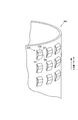
- FIG. 2 is a perspective view showing an inner case disposed inside the rotating electrical machine.
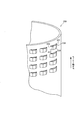
- FIG. 3 is a perspective view showing an inner case in the second embodiment.
- FIG. 4 is a perspective view showing an inner case in the third embodiment.
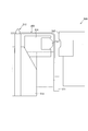
- FIG. 5 is a diagram showing an inner case press working apparatus.
- FIG. 6 is a view when the inner case is arranged in the press working apparatus.
- FIG. 7 is a view when the die is moved to the inner case.
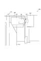
- FIG. 8 is a view when the inner case is pressed with a punch.
- FIG. 9 is a view when the punch is released from the inner case.
- FIG. 10 is a view when the inner case with the convex portions is taken out.
- FIG. 1 is a diagram showing an internal structure of a rotating electrical machine according to the first embodiment of the present invention.
- the rotating electrical machine 100 is, for example, an electric motor mounted on a vehicle.
- An example of the electric motor is a permanent magnet synchronous motor.
- Rotating electric machine 100 includes a rotor 110, a stator 120, and a motor case 130.
- the rotor 110 rotates about the axis together with the motor shaft 101.
- the rotational movement of the rotor 110 is transmitted by the motor shaft 101.
- the rotor 110 is provided with a permanent magnet, for example.
- the stator 120 is disposed on the outer periphery 111 of the rotor 110.
- the stator 120 is provided with teeth at equal intervals in the circumferential direction.
- a coil is wound around the side surface of each tooth.
- the motor case 130 houses the stator 120 together with the rotor 110.
- the rotor 110 and the stator 120 are protected by the motor case 130.
- the inner case 200 having the convex portion 210 on the motor case 130 side is disposed in the rotating electrical machine 100.
- Inner case 200 is fixed on the inner side surface of motor case 130.
- the inner case 200 is a cylindrical casing formed of a member having a relatively high thermal conductivity.
- the stator 120 is disposed on the inner peripheral side, and a large number of convex portions 210 are provided on the outer peripheral side.
- the convex portion 210 secures a space where the stator 120 and the motor case 130 are separated from each other, and vibrations and sounds generated in the stator 120 are hardly transmitted. Furthermore, the convex portion 210 facilitates heat transfer from the stator 120 to the motor case 130.
- the outer peripheral surface 219 is in surface contact with the inner peripheral surface 131 of the motor case 130. Thereby, a contact area with the motor case 130 becomes wide, and the heat dissipation performance from the stator 120 to the motor case 130 can be enhanced.
- the convex portion 210 extends in the motor axial direction.
- the root is fixed to the inner case 200, and the tip in the motor axial direction is separated from the inner case 200. Thereby, the convex part 210 becomes easy to absorb the vibration of the stator 120 or the motor case 130.
- the motor case 130 accommodates the inner case 200 together with the stator 120 in a state where the convex portion 210 is in contact.
- the inner case 200 disposed on the outer peripheral surface of the stator 120 is accommodated in the motor case 130 by press fitting or shrink fitting.
- FIG. 2 is a perspective view showing the convex portion 210 provided on the cylindrical inner case 200.
- the convex portion 210 extends in the motor axial direction as described above.
- the root 211 in the motor axial direction is fixed to the inner case 200, and the tip 212 is separated from the inner case 200. For this reason, the height of the convex part 210 can be easily adjusted according to the space
- FIG. 1
- a contact surface 219 in contact with the motor case 130 is formed on the convex portion 210. Thereby, heat is easily transmitted from the stator 120 to the motor case 130 via the convex portion 210.
- the convex portions 210 are arranged in a grid pattern on the outer peripheral side of the inner case 200. Thereby, since the pressure applied to the convex part 210 is disperse
- the stator 120 is disposed on the inner peripheral side of the cylindrical inner case 200, and the convex portion 210 is provided on the outer peripheral side of the inner case 200.
- the motor case 130 accommodates the inner case 200 together with the stator 120 in a state where the convex portions 210 are in contact with each other.
- stator 120 and the motor case 130 are separated from each other by the convex portion 210, sound vibration is improved, and the thermal conductivity from the stator 120 to the motor case 130 is enhanced by the convex portion 210. Therefore, it is possible to achieve both sound vibration and heat dissipation of the rotating electrical machine 100.
- the outer peripheral surface 219 of the convex portion 210 is in surface contact with the inner peripheral surface 131 of the motor case 130.
- the convex portion 210 extends in the motor axial direction, the root of the convex portion 210 is fixed to the inner case 200, and the tip in the motor axial direction is separated from the inner case 200. Therefore, since the convex part 210 becomes easy to absorb the vibration of the stator 120 or the motor case 130, the sound vibration property of the rotary electric machine 100 can further be improved.
- FIG. 3 is a perspective view showing an inner case having a convex portion 220 in the second embodiment of the present invention.
- a large number of convex portions 220 are arranged on the outer peripheral side of the inner case 200 in the motor axial direction as in the first embodiment.
- the convex part 220 projects in a radial direction perpendicular to the motor axial direction.
- a contact surface 229 that contacts the motor case 130 is formed on the convex portion 220.
- the convex part 220 is extended in the motor axial direction. Both ends 221 and 222 of the convex part 220 are fixed to the inner case 200, and a span (part) 223 between the motor axial directions is separated from the inner case 200.
- the heat dissipation can be improved.
- the span 223 between the convex portions 220 in the motor axial direction is separated from the inner case 200, sound vibration is also improved.
- both ends of the convex portion 220 are fixed to the inner case 200, the rigidity of the convex portion 220 can be increased. Therefore, the contact pressure between the stator 120 and the motor case 130 can be set high to improve the adhesion between the stator 120 and the motor case 130.
- FIG. 4 is a perspective view showing an inner case having a convex portion 230 in the third embodiment of the present invention.
- a large number of convex portions 230 are distributed and arranged on the outer peripheral side of the inner case 200.
- the convex part 230 protrudes in the radial direction orthogonal to the motor axial direction as in the second embodiment.
- a contact surface 239 that contacts the motor case 130 is formed on the convex portion 230.
- the convex portion 230 extends in the circumferential direction of the inner case 200. Both ends 231 and 232 of the convex portion 230 are fixed to the inner case 200, and a span 233 between the circumferential directions of the inner case 200 is separated from the inner case 200.
- the rigidity of the convex portion 220 can be increased. Therefore, the contact pressure between the stator 120 and the motor case 130 can be set high to improve the adhesion between the stator 120 and the motor case 130.
- the convex portion 230 is extended in the circumferential direction of the inner case 200. Accordingly, for example, when the contact surface 239 of the convex portion 230 is formed by press working, the contact surface 239 can be easily adjusted to the curvature of the inner peripheral surface 131 of the motor case 130, so that the contact surface 239 and the inner peripheral surface 131 It is possible to increase the part that actually contacts. Therefore, the heat dissipation of the rotating electrical machine 100 can be improved compared to other embodiments.
- FIG. 5 is a diagram showing a configuration of the press working apparatus 500.
- the press working apparatus 500 includes a lifter 511, a positioning pin 512, a cam driver 513, a cam slider 514, a punch 521, and a die 522.
- the punch 521 is a mold that forms a convex portion 230 on the inner case 200.
- the punch 521 is fitted into the cam slider 514.
- the die 522 is a portion facing the punch 521.
- the die 522 receives the inner case 200 pressed by the punch 521.
- the lifter 511 has a drive mechanism that can adjust the inner case 200 in the vertical direction. For example, the lifter 511 is manually adjusted in the vertical direction.
- the positioning pins 512 are used for projecting the convex portions 230 in a predetermined arrangement direction.
- the cam driver 513 is an electric drive device that drives the cam slider 514 horizontally.
- the cam slider 514 presses the punch 521 against the inner case 200 by the cam driver 513.
- FIG. 6 is a view showing the inner case 200 arranged in the press working apparatus 500.
- the inner case 200 is disposed on a lifter 511 as a workpiece of the press working apparatus 500.
- the lifter 511 is adjusted by the positioning pin 512.
- FIG. 7 is a view showing the press working apparatus 500 when the die 522 is moved to the inner case 200.
- the die 522 is set so as to be in close contact with the outer peripheral surface of the inner case 200.
- FIG. 8 is a view showing a press working apparatus 500 when the punch 521 is pressed on the inner case 200.
- the punch 521 is pressed against the inner peripheral surface of the inner case 200 by the cam driver 513.
- the inner case 200 protrudes in a trapezoidal shape, and the side surface of the protruding convex portion 230 is separated from the inner case 200.
- FIG. 9 is a diagram showing the press working apparatus 500 when the punch 521 is separated from the inner case 200.
- the punch 521 is pulled away from the inner peripheral surface of the inner case 200 by the cam driver 513.
- FIG. 10 is a view showing the press working apparatus 500 when the inner case 200 is taken out. Finally, the die 522 is pulled away from the outer peripheral surface of the inner case 200, and the pressing process is completed.
- the convex portion 230 is formed on the inner case 200 by the press working device 500.
- the convex part 220 shown in FIG. 3 can also be formed by the same method.
Landscapes
- Engineering & Computer Science (AREA)
- Power Engineering (AREA)
- Motor Or Generator Frames (AREA)
- Iron Core Of Rotating Electric Machines (AREA)
Abstract
回転電機は、モーター軸とともに回転するローターと、ローターの外周に配設されたステーターとを有する。そして回転電機は、円筒状であって、内周側にステーターを配置するとともに外周側に凸設された凸部を有するインナーケースと、凸部が当接した状態でステーターとともにインナーケースを収容するモーターケースと、を含む。
Description
この発明は、回転電機のステーターとモーターケースとを固定する構造に関する。
JP2009-183058Aには、ステーターをモーターケース内に圧入し、又は、焼き嵌めることによって、ステーターとモーターケースとを固定する回転電機が開示されている。
前述した回転電機では、モーターケースとステーターとが接触した状態で固定されるため、ステーターで発生した音や振動がモーターケースに直接伝達してしまう。これに対し、ステーターを固定してモーターケースとステーターとを離間すると、ステーターの放熱性能が悪くなるという問題がある。
本発明は、このような問題点に着目してなされた。本発明の目的は、回転電機の放熱性と音振性との両立を図ることにある。
本発明による回転電機のひとつの態様は、モーター軸とともに回転するローターと、前記ローターの外周に配設されたステーターと、を含む回転電機である。この回転電機は、円筒状であって、内周側にステーターを配置するとともに外周側に凸設された凸部を有するインナーケースと、凸部が当接した状態でステーターとともにインナーケースを収容するモーターケースと、を含むことを特徴とする。
以下、添付図面を参照しながら本発明の実施形態について説明する。
(第1実施形態)
図1は、本発明の第1実施形態における回転電機の内部構造を示す図である。
図1は、本発明の第1実施形態における回転電機の内部構造を示す図である。
回転電機100は、例えば、車両に搭載される電動モーターである。電動モーターとしては例えば、永久磁石同期モーターが挙げられる。回転電機100は、ローター110と、ステーター120と、モーターケース130と、を含む。
ローター110は、モーター軸101とともに軸中心に回転する。モーター軸101によってローター110の回転運動が伝達される。ローター110には、例えば永久磁石が設けられている。
ステーター120は、ローター110の外周111に配設される。ステーター120には、円周方向に等間隔でティースが設けられている。各ティースの側面にはコイルが巻かれている。モーターの回転方向に向かって、各ティースに巻き付けられたコイルに順次電流を流すことによって、ローター110の永久磁石がティースに引き寄せられて、ローター110が回転する。
モーターケース130は、ローター110とともにステーター120を収容する。モーターケース130によって、ローター110及びステーター120が保護される。
このような回転電機では、一般的にモーターケースとステーターとが接触した状態で固定されるため、ステーターで発生した音や振動がモーターケースに直接伝達してしまう。これに対し、音振性を改善するために、モーターケースとステーターとを離間させると、ステーターの放熱性能が悪くなるという問題があった。
そこで、本実施形態では、モーターケースとステーターとの間に凸部を設けた円筒状のインナーケースを配置することによって、回転電機の音振性と放熱性の両立を図る。
第1実施形態では、モーターケース130側に凸部210を有するインナーケース200が回転電機100に配置される。インナーケース200は、モーターケース130の内側の側面で固着される。
インナーケース200は、熱伝導性の比較的高い部材で形成される円筒状の筺体である。インナーケース200は、内周側にステーター120を配置するとともに、外周側に多数の凸部210が凸設される。凸部210によって、ステーター120とモーターケース130とが離間するスペースが確保され、ステーター120で生じる振動や音が伝達されにくくなる。さらに凸部210によって、ステーター120からモーターケース130へ熱が伝達されやすくなる。
凸部210では、外周面219がモーターケース130の内周面131に面接触する。これにより、モーターケース130との接触面積が広くなり、ステーター120からモーターケース130への放熱性能を高めることができる。
本実施形態では、凸部210は、モーター軸方向に延設される。凸部210では、根元がインナーケース200に固定され、モーター軸方向の先端がインナーケース200から分離される。これにより、凸部210は、ステーター120又はモーターケース130の振動を吸収しやすくなる。
モーターケース130は、凸部210が当接した状態で、ステーター120とともにインナーケース200を収容する。例えば、モーターケース130には、ステーター120の外周面に配置されたインナーケース200が、圧入又は焼き嵌めによって収容される。
このように、凸部210を有するインナーケース200をステーター120とモーターケース130とで挟むことによって両者が固定されるとともに、放熱性能と音振性能の両立を図ることができる。
図2は、円筒状のインナーケース200に設けられた凸部210を示す斜視図である。
凸部210は、上述のとおり、モーター軸方向に延設されている。そしてモーター軸方向の根元211がインナーケース200に固定され、先端212がインナーケース200から分離されている。このため、ステーター120とモーターケース130との間隔に応じて凸部210の高さを容易に調整できる。
また、凸部210には、モーターケース130と接する接触面219が形成されている。これにより、凸部210を介してステーター120からモーターケース130へ熱が伝達されやすくなる。
凸部210は、インナーケース200の外周側に格子状に分散して配列される。これにより、凸部210に加えられる圧力が分散されるため、凸部210の劣化が抑えられる。よって、回転電機100の放熱性能及び音振性能の劣化を抑制することができる。
本発明の第1実施形態では、円筒状のインナーケース200の内周側にステーター120を配置するとともに、インナーケース200の外周側に凸部210が設けられる。そしてモーターケース130には、凸部210が当接した状態でステーター120とともにインナーケース200が収容される。
このため、凸部210によってステーター120とモーターケース130とが離間するので音振性が向上するとともに、凸部210によってステーター120からモーターケース130への熱伝導性が高まる。したがって、回転電機100の音振性と放熱性との両立を図ることができる。
また、本実施形態では、凸部210の外周面219がモーターケース130の内周面131に面接触する。これにより、ステーター120からモーターケース130へ熱が伝達しやすくなるので、回転電機100の放熱性をより高めることができる。
さらに本実施形態では、凸部210がモーター軸方向に延設され、凸部210の根元がインナーケース200に固定され、モーター軸方向にある先端がインナーケース200から分離される。これにより、凸部210はステーター120又はモーターケース130の振動を吸収しやすくなるので、回転電機100の音振性をさらに高めることができる。
(第2実施形態)
図3は、本発明の第2実施形態における凸部220を有するインナーケースを示す斜視図である。
図3は、本発明の第2実施形態における凸部220を有するインナーケースを示す斜視図である。
インナーケース200の外周側には、多数の凸部220が、第1実施形態と同様、モーター軸方向に配列されている。
凸部220は、モーター軸方向と直交する半径方向に張り出している。凸部220には、モーターケース130と接する接触面229が成形されている。
凸部220は、モーター軸方向に延設されている。凸部220の両端221及び222は、インナーケース200に固定され、モーター軸方向のあいだのスパン(部分)223がインナーケース200から分離されている。
本発明の第2実施形態によれば、第1実施形態と同様、凸部220の外周面229がモーターケース130の内周面131に面接触するので、放熱性を高めることができる。これとともに、凸部220のモーター軸方向のあいだのスパン223がインナーケース200から分離されているので、音振性も高められる。
また、本実施形態では、第2実施形態と異なり、凸部220の両端がインナーケース200に固定されるので、凸部220の剛性を高めることができる。したがって、ステーター120とモーターケース130の接触圧力を高く設定して、ステーター120及びモーターケース130の密着性を高めることが可能となる。
(第3実施形態)
図4は、本発明の第3実施形態における凸部230を有するインナーケースを示す斜視図である。
図4は、本発明の第3実施形態における凸部230を有するインナーケースを示す斜視図である。
インナーケース200の外周側には、多数の凸部230が分散して配列されている。
凸部230は、第2実施形態と同様、モーター軸方向と直交する半径方向に張り出している。凸部230には、モーターケース130と接する接触面239が成形されている。
凸部230は、インナーケース200の円周方向に延設されている。凸部230の両端231及び232は、インナーケース200に固定され、インナーケース200の円周方向のあいだのスパン233は、インナーケース200から分離されている。
本発明の第3実施形態によれば、第2実施形態と同様、凸部230の両端がインナーケース200に固定されるので、凸部220の剛性を高めることができる。したがって、ステーター120とモーターケース130の接触圧力を高く設定して、ステーター120及びモーターケース130の密着性を高めることが可能となる。
また、本実施形態では、第2実施形態と異なり、凸部230がインナーケース200の周方向に延設される。これにより、例えばプレス加工によって凸部230の接触面239を成形するときに、モーターケース130の内周面131の曲率に接触面239を調整しやすくなるので、接触面239と内周面131とが実際に接触する部分を増やすことができる。したがって、他の実施形態に比べて回転電機100の放熱性を高めることができる。
次にインナーケース200に凸設される凸部230を形成する方法について簡単に説明する。
図5は、プレス加工装置500の構成を示す図である。
プレス加工装置500は、リフター511と、位置決めピン512と、カムドライバー513と、カムスライダー514と、ポンチ521と、ダイ522と、を含む。
ポンチ521は、インナーケース200に凸部230を形成する型である。ポンチ521は、カムスライダー514に嵌め込まれている。
ダイ522は、ポンチ521に対向する部分である。ダイ522は、ポンチ521によってプレスされたインナーケース200を受け入れる。
リフター511は、インナーケース200を上下方向に調整可能な駆動機構を有する。例えば、リフター511は、手動によって上下方向に調整される。
位置決めピン512は、予め定められた配列方向に凸部230を凸設するために用いられる。
カムドライバー513は、カムスライダー514を水平に駆動する電動式の駆動装置である。
カムスライダー514は、カムドライバー513によってポンチ521をインナーケース200に押し付ける。
図6は、プレス加工装置500に配置されたインナーケース200を示す図である。プレス加工装置500のワークとして、インナーケース200はリフター511に配置される。そして位置決めピン512によってリフター511が調整される。
図7は、ダイ522をインナーケース200に移動したときのプレス加工装置500を示す図である。ダイ522は、インナーケース200の外周面に密着するように設定される。
図8は、ポンチ521をインナーケース200にプレスしたときのプレス加工装置500を示す図である。カムドライバー513によってポンチ521がインナーケース200の内周面に押しあてられる。これにより、インナーケース200が台形に張り出され、張り出した凸部230の側面はインナーケース200から切り離される。
図9は、インナーケース200からポンチ521を離したときのプレス加工装置500を示す図である。カムドライバー513によってインナーケース200の内周面からポンチ521が引き離される。
図10は、インナーケース200を取り出すときのプレス加工装置500を示す図である。最後にダイ522がインナーケース200の外周面から引き離されてプレス加工処理が終了する。
このように、プレス加工装置500によってインナーケース200に凸部230が形成される。なお、図3に示した凸部220も同じ方法によって形成することができる。
以上、本発明の実施形態について説明したが、上記実施形態は本発明の適用例の一部を示したに過ぎず、本発明の技術的範囲を上記実施形態の具体的構成に限定する趣旨ではない。
なお、上記実施形態は、適宜組み合わせ可能である。
本願は、2013年2月21日に日本国特許庁に出願された特願2013-32281に基づく優先権を主張し、この出願の全ての内容は参照により本明細書に組み込まれる。
Claims (5)
- モーター軸とともに回転するローターと、
前記ローターの外周に配設されたステーターと、
円筒状であって、内周側に前記ステーターを配置するとともに外周側に凸設された凸部を有するインナーケースと、
前記凸部が当接した状態で前記ステーターとともに前記インナーケースを収容するモーターケースと、
を含む回転電機。 - 請求項1に記載の回転電機であって、
前記凸部は、外周面がモーターケースの内周面に面接触する、
回転電機。 - 請求項1又は請求項2に記載の回転電機であって、
前記凸部は、モーター軸方向に延設され、根元が前記インナーケースに固定され、モーター軸方向先端が前記インナーケースから分離される、
回転電機。 - 請求項1又は請求項2に記載の回転電機であって、
前記凸部は、モーター軸方向に延設され、両端が前記インナーケースに固定され、モーター軸方向のあいだのスパンが前記インナーケースから分離される、
回転電機。 - 請求項1又は請求項2に記載の回転電機であって、
前記凸部は、前記インナーケースの円周方向に延設され、両端が前記インナーケースに固定され、前記インナーケースの円周方向のあいだのスパンが前記インナーケースから分離される、
回転電機。
Priority Applications (1)
| Application Number | Priority Date | Filing Date | Title |
|---|---|---|---|
| JP2015501288A JP5843044B2 (ja) | 2013-02-21 | 2013-12-17 | 回転電機 |
Applications Claiming Priority (2)
| Application Number | Priority Date | Filing Date | Title |
|---|---|---|---|
| JP2013032281 | 2013-02-21 | ||
| JP2013-032281 | 2013-02-21 |
Publications (1)
| Publication Number | Publication Date |
|---|---|
| WO2014129062A1 true WO2014129062A1 (ja) | 2014-08-28 |
Family
ID=51390873
Family Applications (1)
| Application Number | Title | Priority Date | Filing Date |
|---|---|---|---|
| PCT/JP2013/083714 Ceased WO2014129062A1 (ja) | 2013-02-21 | 2013-12-17 | 回転電機 |
Country Status (2)
| Country | Link |
|---|---|
| JP (1) | JP5843044B2 (ja) |
| WO (1) | WO2014129062A1 (ja) |
Cited By (5)
| Publication number | Priority date | Publication date | Assignee | Title |
|---|---|---|---|---|
| WO2019235537A1 (ja) * | 2018-06-08 | 2019-12-12 | アイシン・エィ・ダブリュ株式会社 | 回転電機及び回転電機を備えた車両用駆動装置 |
| JP2019221035A (ja) * | 2018-06-18 | 2019-12-26 | 三菱電機株式会社 | 回転電機および回転電機の製造方法 |
| WO2020137040A1 (ja) * | 2018-12-28 | 2020-07-02 | 株式会社マキタ | 電動工具用の分布巻きモータ及び電動工具 |
| EP3836368A1 (fr) | 2019-12-12 | 2021-06-16 | Valeo Equipements Electriques Moteur | Machine électrique tournante comportant un organe élastique |
| WO2022071358A1 (ja) * | 2020-09-30 | 2022-04-07 | ダイキン工業株式会社 | コア、回転電気機械、及び静止器 |
Citations (3)
| Publication number | Priority date | Publication date | Assignee | Title |
|---|---|---|---|---|
| JPH0662759U (ja) * | 1993-02-10 | 1994-09-02 | 株式会社三協精機製作所 | 小型モータ |
| JP2000134856A (ja) * | 1998-10-21 | 2000-05-12 | Tokyo Parts Ind Co Ltd | 磁石回転型モータのハウジング構造 |
| JP2011223810A (ja) * | 2010-04-13 | 2011-11-04 | Toyota Motor Corp | 回転電機 |
-
2013
- 2013-12-17 JP JP2015501288A patent/JP5843044B2/ja active Active
- 2013-12-17 WO PCT/JP2013/083714 patent/WO2014129062A1/ja not_active Ceased
Patent Citations (3)
| Publication number | Priority date | Publication date | Assignee | Title |
|---|---|---|---|---|
| JPH0662759U (ja) * | 1993-02-10 | 1994-09-02 | 株式会社三協精機製作所 | 小型モータ |
| JP2000134856A (ja) * | 1998-10-21 | 2000-05-12 | Tokyo Parts Ind Co Ltd | 磁石回転型モータのハウジング構造 |
| JP2011223810A (ja) * | 2010-04-13 | 2011-11-04 | Toyota Motor Corp | 回転電機 |
Cited By (12)
| Publication number | Priority date | Publication date | Assignee | Title |
|---|---|---|---|---|
| WO2019235537A1 (ja) * | 2018-06-08 | 2019-12-12 | アイシン・エィ・ダブリュ株式会社 | 回転電機及び回転電機を備えた車両用駆動装置 |
| CN112136268A (zh) * | 2018-06-08 | 2020-12-25 | 爱信艾达株式会社 | 旋转电机以及具备旋转电机的车用驱动装置 |
| JPWO2019235537A1 (ja) * | 2018-06-08 | 2021-04-22 | アイシン・エィ・ダブリュ株式会社 | 回転電機及び回転電機を備えた車両用駆動装置 |
| JP2019221035A (ja) * | 2018-06-18 | 2019-12-26 | 三菱電機株式会社 | 回転電機および回転電機の製造方法 |
| JP7209480B2 (ja) | 2018-06-18 | 2023-01-20 | 三菱電機株式会社 | 回転電機および回転電機の製造方法 |
| WO2020137040A1 (ja) * | 2018-12-28 | 2020-07-02 | 株式会社マキタ | 電動工具用の分布巻きモータ及び電動工具 |
| EP3836368A1 (fr) | 2019-12-12 | 2021-06-16 | Valeo Equipements Electriques Moteur | Machine électrique tournante comportant un organe élastique |
| FR3104850A1 (fr) * | 2019-12-12 | 2021-06-18 | Valeo Equipements Electriques Moteur | Machine électrique tournante comportant un organe élastique |
| CN112994331A (zh) * | 2019-12-12 | 2021-06-18 | 法雷奥电机设备公司 | 包括弹性单元的旋转电机 |
| WO2022071358A1 (ja) * | 2020-09-30 | 2022-04-07 | ダイキン工業株式会社 | コア、回転電気機械、及び静止器 |
| JP2022056576A (ja) * | 2020-09-30 | 2022-04-11 | ダイキン工業株式会社 | コア、回転電気機械、及び静止器 |
| JP7189452B2 (ja) | 2020-09-30 | 2022-12-14 | ダイキン工業株式会社 | コア、回転電気機械、及び静止器 |
Also Published As
| Publication number | Publication date |
|---|---|
| JPWO2014129062A1 (ja) | 2017-02-02 |
| JP5843044B2 (ja) | 2016-01-13 |
Similar Documents
| Publication | Publication Date | Title |
|---|---|---|
| JP5253789B2 (ja) | ブラシレスモータ | |
| JP5862145B2 (ja) | モータおよびモータの製造方法 | |
| JP5843044B2 (ja) | 回転電機 | |
| JP5288065B1 (ja) | モータ | |
| JP5958439B2 (ja) | 回転子、および、これを用いた回転電機 | |
| JP6298161B2 (ja) | 固定子コイル、固定子、電磁装置、ならびに、固定子コイルの製造方法 | |
| JP6353722B2 (ja) | バスバーユニット及びこれを備えた回転電機 | |
| JP2015122880A (ja) | モータ及びバスバーユニット | |
| WO2015163039A1 (ja) | 電動圧縮機 | |
| JP6608304B2 (ja) | モータおよび減速機付モータ | |
| CN218678565U (zh) | 外转子电机 | |
| JPWO2014181576A1 (ja) | 回転電機の磁石飛散防止及び保持構造 | |
| JPWO2018087887A1 (ja) | 回転電機の固定子およびその製造方法 | |
| JP2013009571A (ja) | モータ | |
| WO2018179736A1 (ja) | ロータ及びロータを備えたモータ | |
| WO2017122606A1 (ja) | ステータ、モータ及びステータの製造方法 | |
| JP4119661B2 (ja) | 電動機の固定子およびその製造方法 | |
| CN103683555A (zh) | 定子和旋转电机 | |
| JP2010124661A (ja) | 回転電機 | |
| JP2005045890A (ja) | 回転機 | |
| JP5448252B2 (ja) | 回転電機及びロボット | |
| JP2018201302A (ja) | モータ | |
| JP2018085818A (ja) | ステッピングモータ | |
| JP6341230B2 (ja) | モータ | |
| JP5643038B2 (ja) | 回転電機用ロータ |
Legal Events
| Date | Code | Title | Description |
|---|---|---|---|
| 121 | Ep: the epo has been informed by wipo that ep was designated in this application |
Ref document number: 13875677 Country of ref document: EP Kind code of ref document: A1 |
|
| ENP | Entry into the national phase |
Ref document number: 2015501288 Country of ref document: JP Kind code of ref document: A |
|
| NENP | Non-entry into the national phase |
Ref country code: DE |
|
| 122 | Ep: pct application non-entry in european phase |
Ref document number: 13875677 Country of ref document: EP Kind code of ref document: A1 |