WO2014126004A1 - 車両用灯具 - Google Patents
車両用灯具 Download PDFInfo
- Publication number
- WO2014126004A1 WO2014126004A1 PCT/JP2014/052853 JP2014052853W WO2014126004A1 WO 2014126004 A1 WO2014126004 A1 WO 2014126004A1 JP 2014052853 W JP2014052853 W JP 2014052853W WO 2014126004 A1 WO2014126004 A1 WO 2014126004A1
- Authority
- WO
- WIPO (PCT)
- Prior art keywords
- reflector
- light
- sub
- lamp
- light source
- Prior art date
- Legal status (The legal status is an assumption and is not a legal conclusion. Google has not performed a legal analysis and makes no representation as to the accuracy of the status listed.)
- Ceased
Links
Images



Classifications
-
- F—MECHANICAL ENGINEERING; LIGHTING; HEATING; WEAPONS; BLASTING
- F21—LIGHTING
- F21S—NON-PORTABLE LIGHTING DEVICES; SYSTEMS THEREOF; VEHICLE LIGHTING DEVICES SPECIALLY ADAPTED FOR VEHICLE EXTERIORS
- F21S41/00—Illuminating devices specially adapted for vehicle exteriors, e.g. headlamps
- F21S41/10—Illuminating devices specially adapted for vehicle exteriors, e.g. headlamps characterised by the light source
- F21S41/12—Illuminating devices specially adapted for vehicle exteriors, e.g. headlamps characterised by the light source characterised by the type of emitted light
- F21S41/125—Coloured light
-
- F—MECHANICAL ENGINEERING; LIGHTING; HEATING; WEAPONS; BLASTING
- F21—LIGHTING
- F21S—NON-PORTABLE LIGHTING DEVICES; SYSTEMS THEREOF; VEHICLE LIGHTING DEVICES SPECIALLY ADAPTED FOR VEHICLE EXTERIORS
- F21S41/00—Illuminating devices specially adapted for vehicle exteriors, e.g. headlamps
- F21S41/10—Illuminating devices specially adapted for vehicle exteriors, e.g. headlamps characterised by the light source
- F21S41/14—Illuminating devices specially adapted for vehicle exteriors, e.g. headlamps characterised by the light source characterised by the type of light source
- F21S41/162—Incandescent light sources, e.g. filament or halogen lamps
- F21S41/164—Incandescent light sources, e.g. filament or halogen lamps having two or more filaments
-
- F—MECHANICAL ENGINEERING; LIGHTING; HEATING; WEAPONS; BLASTING
- F21—LIGHTING
- F21S—NON-PORTABLE LIGHTING DEVICES; SYSTEMS THEREOF; VEHICLE LIGHTING DEVICES SPECIALLY ADAPTED FOR VEHICLE EXTERIORS
- F21S41/00—Illuminating devices specially adapted for vehicle exteriors, e.g. headlamps
- F21S41/20—Illuminating devices specially adapted for vehicle exteriors, e.g. headlamps characterised by refractors, transparent cover plates, light guides or filters
- F21S41/285—Refractors, transparent cover plates, light guides or filters not provided in groups F21S41/24 - F21S41/2805
-
- F—MECHANICAL ENGINEERING; LIGHTING; HEATING; WEAPONS; BLASTING
- F21—LIGHTING
- F21S—NON-PORTABLE LIGHTING DEVICES; SYSTEMS THEREOF; VEHICLE LIGHTING DEVICES SPECIALLY ADAPTED FOR VEHICLE EXTERIORS
- F21S41/00—Illuminating devices specially adapted for vehicle exteriors, e.g. headlamps
- F21S41/20—Illuminating devices specially adapted for vehicle exteriors, e.g. headlamps characterised by refractors, transparent cover plates, light guides or filters
- F21S41/29—Attachment thereof
-
- F—MECHANICAL ENGINEERING; LIGHTING; HEATING; WEAPONS; BLASTING
- F21—LIGHTING
- F21S—NON-PORTABLE LIGHTING DEVICES; SYSTEMS THEREOF; VEHICLE LIGHTING DEVICES SPECIALLY ADAPTED FOR VEHICLE EXTERIORS
- F21S41/00—Illuminating devices specially adapted for vehicle exteriors, e.g. headlamps
- F21S41/30—Illuminating devices specially adapted for vehicle exteriors, e.g. headlamps characterised by reflectors
- F21S41/32—Optical layout thereof
- F21S41/321—Optical layout thereof the reflector being a surface of revolution or a planar surface, e.g. truncated
-
- F—MECHANICAL ENGINEERING; LIGHTING; HEATING; WEAPONS; BLASTING
- F21—LIGHTING
- F21S—NON-PORTABLE LIGHTING DEVICES; SYSTEMS THEREOF; VEHICLE LIGHTING DEVICES SPECIALLY ADAPTED FOR VEHICLE EXTERIORS
- F21S41/00—Illuminating devices specially adapted for vehicle exteriors, e.g. headlamps
- F21S41/30—Illuminating devices specially adapted for vehicle exteriors, e.g. headlamps characterised by reflectors
- F21S41/32—Optical layout thereof
- F21S41/33—Multi-surface reflectors, e.g. reflectors with facets or reflectors with portions of different curvature
- F21S41/338—Multi-surface reflectors, e.g. reflectors with facets or reflectors with portions of different curvature the reflector having surface portions added to its general concavity
-
- F—MECHANICAL ENGINEERING; LIGHTING; HEATING; WEAPONS; BLASTING
- F21—LIGHTING
- F21S—NON-PORTABLE LIGHTING DEVICES; SYSTEMS THEREOF; VEHICLE LIGHTING DEVICES SPECIALLY ADAPTED FOR VEHICLE EXTERIORS
- F21S41/00—Illuminating devices specially adapted for vehicle exteriors, e.g. headlamps
- F21S41/30—Illuminating devices specially adapted for vehicle exteriors, e.g. headlamps characterised by reflectors
- F21S41/32—Optical layout thereof
- F21S41/36—Combinations of two or more separate reflectors
- F21S41/365—Combinations of two or more separate reflectors successively reflecting the light
-
- F—MECHANICAL ENGINEERING; LIGHTING; HEATING; WEAPONS; BLASTING
- F21—LIGHTING
- F21W—INDEXING SCHEME ASSOCIATED WITH SUBCLASSES F21K, F21L, F21S and F21V, RELATING TO USES OR APPLICATIONS OF LIGHTING DEVICES OR SYSTEMS
- F21W2102/00—Exterior vehicle lighting devices for illuminating purposes
- F21W2102/10—Arrangement or contour of the emitted light
- F21W2102/17—Arrangement or contour of the emitted light for regions other than high beam or low beam
- F21W2102/18—Arrangement or contour of the emitted light for regions other than high beam or low beam for overhead signs
Definitions
- the present invention relates to a vehicular lamp having excellent visibility such as a sign provided above the head of an expressway, a so-called overhead sign.
- the present invention relates to a vehicular lamp that is excellent in visibility in front of a vehicle by irradiating a part of light source light upward and forward with a sub-reflector provided in the lamp chamber.
- Patent Document 1 a reflector in which a light source (bulb) is inserted in a lamp chamber is provided, and a flat sub-reflector is arranged substantially horizontally at a predetermined position in front of the reflector.
- a “vehicle headlamp” in which a part of light source light reflected by a reflector is further reflected by an upper surface of a sub-reflector and is emitted upward and forward from a lamp chamber to irradiate an overhead sign.
- the present invention has been made in view of the above-described problems of the prior art, and its purpose is to provide a sub-reflector that forms upward illumination light in front of the lamp, thereby reducing the original light distribution of the lamp.
- the object is to provide a vehicular lamp that can improve visibility in front of the vehicle.
- an aspect of the vehicular lamp according to the present invention includes a light source and a reflector that reflects light source light emitted from the light source forward in a lamp chamber, and the outside of the light source.
- a sub-reflector having reflection surfaces on both front and back sides thereof and extending in the front-rear direction of the lamp chamber is disposed in front of the reflector, and a part of the light source light is reflected by the reflection surface of the sub-reflector to front the lamp. It was configured to irradiate upward and downward, respectively.
- part of the light source light (reflected light from the effective reflecting surface of the reflector) that contributes to the formation of the original light distribution of the lamp is reflected by the upper surface of the sub-reflector and irradiated upward, the original distribution of the lamp
- the amount of light may decrease
- a part of the light source light is reflected by the lower surface of the sub-reflector and is irradiated downward in front of the lamp, and the irradiation light downward in front of the lamp compensates for the decrease in the original light distribution of the lamp.
- the sub reflector is disposed in front of a straight line connecting a light emission center of the light source and an outer edge of an effective reflection surface of the reflector, and the reflector is effective.
- the direct light from the light source in the sub-reflector which is light that does not contribute to the original light distribution of the lamp, is reflected by the sub-reflector (the upper surface or the lower surface) and radiated forward (upward or downward) of the lamp.
- the light distribution of the lamp increases.
- the sub-reflector may be configured in a substantially V-shape or U-shape in front view including a pair of left and right inclined side walls.
- the irradiation light reflected from the upper surface of the sub-reflector and irradiated upward in the front direction of the lamp becomes a light distribution that is largely diffused to the left and right in front of the vehicle. Further, the irradiation light reflected from the lower surface of the sub-reflector and irradiated downward in front of the lamp is a light distribution that is largely diffused to the left and right of the front of the vehicle.
- the sub reflector may be disposed above the light source, and an inner lens may be provided on the optical path of the light reflected upward and upward on the upper surface of the sub reflector.
- the irradiation range of the lamp front upward irradiation light that is, the emission direction of the lamp front upward irradiation light can be controlled by the shape of the auxiliary reflection surface of the reflector and the upper surface (reflection surface) of the sub-reflector. It can also be controlled by steps.
- the inner lens may be configured to be colored in a predetermined color.
- the area corresponding to the inner lens of the front cover that defines the lamp chamber emits light in a predetermined color.
- the colored inner lens reliably prevents the lamp chamber from being seen through the front cover.
- the visibility in the upper front of the vehicle is increased without reducing the original light distribution of the lamp.
- the characteristics are greatly improved.
- the vehicular lamp of the above (2) in addition to the fact that most of the light source light is used as the original light distribution of the lamp, the light source light that does not contribute to the formation of the original light distribution of the lamp also passes through the sub-reflector. Therefore, the visibility in the front of the vehicle is reliably improved.
- the irradiation light reflected on the upper or lower surface of the sub-reflector and irradiated on the front or upper side of the lamp is a light distribution that is greatly diffused to the left and right of the vehicle. Visibility in a wide range on the left and right is improved.
- the emission direction of the upward illumination light of the lamp is controlled by combining the auxiliary reflecting surface of the reflector, the shape of the upper surface (reflecting surface) of the sub-reflector, and the lens step of the inner lens. Therefore, the light distribution design that forms the upward illumination light in front of the lamp is facilitated, and accurate illumination of a predetermined range in front of the vehicle by the sub reflector is possible.
- the vehicular lamp of (5) when the lamp is not lit, the interior of the lamp chamber cannot be seen through the outer lens, and when the lamp is lit, a predetermined area of the outer lens emits light in a predetermined color of the inner lens. A novel appearance is secured.
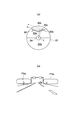
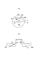
- FIG. 1 is a front view of a motorcycle headlamp according to a first embodiment of the present invention. It is a longitudinal cross-sectional view (cross-sectional view along line II-II shown in FIG. 1) of the headlamp. It is a figure which shows the light distribution of the passing beam of the headlamp, (a) is a figure which shows the light distribution at the time of straight running, (b) is a figure which shows the light distribution at the time of bank running which curves to the left. (A) is a figure which shows the emission direction of the light source light reflected by the upper surface of the sub reflector, (b) is a figure which shows the light distribution formed with the light source light reflected by the upper surface of the sub reflector.
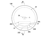
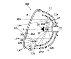
- FIG. 6 is a front view of a motorcycle headlamp according to a second embodiment of the present invention. It is a longitudinal cross-sectional view (cross-sectional view which follows the line VIII-VIII shown in FIG. 7) of the headlamp.
- 1 to 6 show a first embodiment in which the present invention is applied to, for example, a motorcycle headlamp.
- the motorcycle headlamp 10 includes a container-shaped lamp body 12 that opens forward, and a transparent front cover 14 that is assembled to the front opening of the lamp body 12.
- a light source unit 20 that forms a predetermined light distribution is accommodated.
- the light source unit 20 is formed by integrating a bulb 24 as a light source into a bulb insertion hole 23 of a reflector 22.
- the light source unit 20 is configured to be tiltable in the vertical and horizontal directions (the optical axis L of the light source unit 20 is tiltable) by an aiming mechanism (not shown) interposed between the reflector 22 and the lamp body 12. .
- the reflector 22 includes parabolic effective reflecting surfaces 22a and 22b (the reflecting surface above the optical axis L is indicated by 22a and the reflecting surface below is indicated by 22b).
- the bulb 24 includes, on the optical axis L, a front first filament 26a that is a light source for passing beam and a rear second filament 26b that is a light source for forming a passing beam and a traveling beam. ing.
- the first filament 26a is disposed in front of the focal point F of the effective reflection surfaces 22a and 22b of the reflector 22.
- a shade 27 that shields light from the first filament 26a toward the lower effective reflection surface 22b is provided below the first filament 26a. For this reason, most of the light emitted from the first filament 26a is reflected by the upper effective reflection surface 22a of the reflector 22, and is transmitted through the front cover 14 and emitted downward in front of the lamp, as indicated by reference numeral La in FIG.
- a light distribution Pa (see FIG. 3) of a predetermined passing beam is formed.
- the second filament 26b is disposed on the focal point F of the effective reflection surface 22a of the reflector 22.
- the light emitted from the filament 26b is reflected by the upper and lower effective reflecting surfaces 22a and 22b, and becomes light Lb substantially parallel to the optical axis L as shown by a symbol Lb in FIG. To exit.
- a light distribution (not shown) of a predetermined traveling beam is formed.
- reference numeral 28 in FIG. 2 denotes a shading coating portion for preventing glare light generation, which is referred to as a black top provided at the tip of the bulb 24.
- a sub reflector 30 is disposed above the bulb 24 in the lamp chamber S and in front of the reflector 22.
- the sub reflector 30 has reflection surfaces 32a and 32b on both front and back (upper and lower) sides thereof and extends in the front-rear direction of the lamp chamber S.
- an extension reflector (not shown) disposed between the front cover 12 and the reflector 22 is provided. It is fixed horizontally and is arranged horizontally.
- an inner lens 40 is disposed in front of the sub reflector 30 in the lamp chamber S.
- the inner lens 40 is integrated with, for example, an extension reflector (not shown), and is disposed so as to cross the optical path of light that is reflected by the upper surface 30a of the sub-reflector 30 and irradiated upward in front of the lamp.
- an auxiliary reflecting surface 22 c that reflects the light source light toward the sub reflector 30 is integrally formed outside the outer edge 22 a 1 of the upper effective reflecting surface 22 a of the reflector 22.
- a part of the light emitted from the first filament 26a is irradiated by the sub-reflector 30 upward and downward, respectively.
- the sub reflector 30 is formed in a substantially V shape in front view including a pair of left and right inclined side walls 31, 31. Further, as shown in FIG. 2, the sub reflector 30 is disposed in front of a straight line L ⁇ b> 0 that connects the light emission center of the first filament 26 a and the outer edge 22 a 1 of the upper effective reflection surface 22 a of the reflector 22. With this configuration, light emitted from the first filament 26a that does not contribute exclusively to the light distribution of the lamp is guided to the sub-reflector 30 (the reflecting surface 30a) by the auxiliary reflecting surface 22c of the reflector 22.
- the first filament 26 a changes to the effective reflection surface 22 a of the reflector 22.
- the light that travels (the light that contributes to the formation of the light distribution of the passing beam and the traveling beam) is not blocked by the sub reflector 30. Therefore, most of the light emission of the first filament 26a can be used to form the original light distribution (light distribution of the passing beam and the traveling beam).
- light from the second filament 26 b toward the effective reflection surface 22 a of the reflector 22 (light that contributes to the formation of the light distribution of the traveling beam) is not shielded by the sub reflector 30. Therefore, most of the light emitted from the second filament 26b can be used to form the original light distribution of the lamp (light distribution of the traveling beam).
- the sub-reflector 30 formed in a substantially V shape in front view is arranged in parallel to the optical axis L. For this reason, the light reflected by the effective reflection surfaces 22a and 22b of the reflector 22 (light that contributes to the formation of the light distribution of the passing beam and the traveling beam) is not shielded by the sub-reflector 30, and the sub-reflector 30 has an appropriate passing beam. And does not hinder the formation of the light distribution of the traveling beam.
- the sub-reflector 30 is disposed in front of a straight line L0 that connects the light emission center of the first filament 26a and the outer edge 22a1 of the upper effective reflection surface 22a of the reflector 22.
- the auxiliary reflecting surface 22c After a part of the light emitted from the first filament 26a is reflected by the auxiliary reflecting surface 22c, it is reflected by the upper surface 30a of the sub-reflector 30 and is irradiated upward in the lamp direction as indicated by L1 in FIG. .
- the upper surface 30a of the sub-reflector 30, which is a reflection surface, is inclined in a V shape when viewed from the front, this irradiation light is greatly diffused outward in the vehicle width direction as shown in FIG.
- a wide area PSa above the horizontal line on the outer side in the road width direction is illuminated.
- the light traveling forward from the auxiliary reflecting surface 22c is reflected by the lower surface 30b of the sub-reflector 30 and is irradiated downward in front of the lamp, as indicated by reference numeral L2 in FIG. .
- the lower surface 30b of the sub-reflector 30 which is a reflection surface, is inclined in a V shape when viewed from the front, this irradiation light is greatly diffused outward in the vehicle width direction as shown in FIG.
- a wide area PSb below the horizontal line outside the road width direction is illuminated.
- the light distribution PSa and PSb formed by the sub-reflector 30 are added to the light distribution Pa of the passing beam.
- Part of the light emitted by the second filament 26b is also reflected by the auxiliary reflecting surface 22c, then reflected by the upper surface 30a of the sub-reflector 30 and irradiated upward in the front of the lamp, and is greatly diffused outward in the vehicle width direction.
- the irradiation light by a part of the light emission of the second filament 26b also illuminates a range (see FIG. 4B) substantially the same as the irradiation light formed by the light emission of the first filament 26a.
- the irradiation light reflected from the lower surface 30b of the sub-reflector 30 and irradiated downward in front of the lamp is also greatly diffused outward in the vehicle width direction, and the light emitted from the first filament 26a. Illuminates a range substantially similar to the irradiation light formed by (see FIG. 5B).
- the light distribution PSa, PSb (see FIGS. 4 and 5) formed by the sub reflector 30 is added to the light distribution of the different traveling beam, so that a wide area in the left-right direction in front of the vehicle is illuminated. For this reason, the visibility in front of the vehicle is greatly improved.
- the inner lens 40 disposed in front of the sub reflector 30 is colored blue. For this reason, when the lamp is lit, the region corresponding to the inner lens 40 of the outer lens 12 emits blue light. On the other hand, when the lamp is not lit, the inner lens 40 colored blue can surely prevent the interior of the lamp chamber S from being seen through the front cover 14. Therefore, the novel appearance of the lamp 10 is ensured.
- the fact that part of the lamp illumination light is blue is due to the Burkien phenomenon at sunset (a phenomenon in which the sensitivity characteristic of eye brightness shifts to the short wavelength side when suddenly moving from a bright place to a dark place). Since the blue color appears relatively bright, visibility in front of the vehicle is improved.
- the upward and leftward diffused light irradiation directions formed by the upper surface (reflecting surface) 30a of the sub reflector 30 are the shape of the auxiliary reflecting surface 22c of the reflector 22, the shape of the upper surface (reflecting surface) 30a of the sub reflector 30, and the inner
- the light source direct light at the sub-reflector 30 that is light that does not contribute to the formation of the light distribution of the lamp 10 is reflected by the lower surface 30b of the sub-reflector 30 and diffused and distributed to the front downward and left and right of the lamp 10 (FIG. 5 (b) reference PSb). For this reason, the visibility of the wide area
- the light reflected from the upper surface 30a of the sub-reflector 30 and irradiated upward in the forward direction of the lamp is higher than the horizontal line on the outer side in the road width direction as shown in FIG. A wide area PSa is illuminated.
- the light reflected from the upper surface 30a of the sub-reflector 30 and radiated upward in front of the lamp illuminates the far side in the traveling direction of the curved road as shown by the symbol PSa in FIG. Will be. For this reason, the front visibility at the time of bank running is excellent.
- FIG. 6 shows a modification of the first embodiment in which the shape of the sub-reflector indicated by reference numeral 30 in FIG. 1 is changed.
- the sub-reflector 30 is formed in a substantially V shape in front view including a pair of left and right inclined side walls 31, 31.
- the sub-reflector 30A is formed in a substantially U shape in front view in which a pair of right and left inclined side walls 31a and 31a are formed on both sides of the flat bottom wall 31b in the width direction.
- the irradiation light formed by the sub-reflector 30A is reflected by the upper and lower surfaces of the flat bottom wall 31b, and is irradiated respectively upward and downward of the lamp.
- the irradiation range in front of the vehicle is enlarged.
- the lamp front upward irradiation light is diffused greatly outward in the width direction from the front of the vehicle, and illuminates a wide area above the horizontal line from the upper side of the road to the outer side in the road width direction, as indicated by reference sign PSa ′ in FIG. To do.
- a part of the light emitted from the bulb 24 is reflected by the lower surface 30 b ′ of the sub-reflector 30, thereby forming irradiation light downward in the front of the lamp.
- the lamp front downward irradiation light is diffused greatly from the front of the vehicle to the outside in the width direction, and illuminates a wide area on the left and right from the front of the road below the horizontal line, as indicated by reference sign PSb 'in FIG.
- the headlamp 10A of the present embodiment a light distribution with excellent visibility in a wide range in front of the vehicle including an overhead sign can be obtained.
- FIG. 7 and 8 show a motorcycle head lamp according to a second embodiment of the present invention.
- the sub reflectors 30 and 30A are disposed at a predetermined position in front of the reflector 22 above the bulb 24 in the lamp chamber S. A part of the light emitted from the bulb 24 (first and second filaments 26a and 26b) is irradiated upward and downward from the lamp through the sub-reflectors 30 and 30A arranged in this way. Yes. With this configuration, the visibility in front of the vehicle in both the passing beam and the traveling beam is improved.
- the sub-reflector 30B is horizontally disposed at a predetermined position in front of the reflector 22 below the bulb 24 in the lamp chamber S. A part of the light emitted from the bulb 24 (second filament 26b) is irradiated to the front upward and downward of the lamp 10B via the sub-reflector 30B arranged in this way. With this configuration, the visibility in front of the vehicle in the traveling beam is improved.
- the sub-reflector 30B is disposed in front of a straight line L0 that connects the emission center of the second filament 26b of the bulb 24 and the outer edge 22b1 of the lower effective reflection surface 22b of the reflector 22.
- the sub-reflector 30B the reflecting surface 30b
- the auxiliary reflecting surface 22d of the reflector 22 the auxiliary reflecting surface 22d of the reflector 22. That is, most of the light emitted from the bulb 24 (second filament 26b) is directed to the lower effective reflection surface 22b of the reflector 22 without being shielded from light, so that the original light distribution of the lamp 10B is ensured.
- the sub-reflector 30B has a pair of left and right inclined side walls 31 and 31, which are substantially the same as those of the sub-reflector 30 used in the lamp 10 of the first embodiment. It is formed in a letter shape. Further, an auxiliary reflecting surface 22d that reflects light emitted from the bulb 24 (second filament 26b) toward the lower surface 30b of the sub-reflector 30B is disposed outside the outer edge 22b1 of the effective reflecting surface 22b below the reflector 22. Are integrally formed.
- a part of the light emitted from the second filament 26b (light emitted from the second filament 26b that travels forward from the auxiliary reflecting surface 22d) is generated by the sub-reflector 30B as indicated by reference numeral L3 in FIG.
- the light is reflected by the upper surface 30a, passes through the inner lens 40A integrated with the front cover 14, and is irradiated upward in the front of the lamp. Since the upper surface 30a of the sub-reflector 30B, which is a reflection surface, is inclined in a V shape when viewed from the front, this irradiation light is diffused greatly outward in the vehicle width direction, and is wide above the horizontal line and on the left and right outer sides of the road.
- the area PSa (see FIG. 4B) is illuminated.
- the inner lens 40 is integrated with the extension reflector so as to cross the optical path of the forward upward irradiation light L1 reflected by the upper surface 30a of the sub reflector 30.
- the inner lens 40A colored blue is integrally formed on the transparent front cover 12 so as to cross the optical path of the front upward irradiation light L3 reflected by the upper surface 30a of the sub reflector 30B. Has been.
- the inner lens 40A is provided inside the front cover 14 corresponding to the sub reflector 30B. For this reason, a part of the light reflected by the effective reflection surface 22a of the reflector 22 and contributing to the formation of the light distribution of the predetermined passing beam or the traveling beam is transmitted through the inner lens 40A, but is transmitted through the inner lens 40A. In this case, since light is refracted downward, the formation of the light distribution of a predetermined passing beam or traveling beam is not hindered.
Landscapes
- Engineering & Computer Science (AREA)
- General Engineering & Computer Science (AREA)
- Non-Portable Lighting Devices Or Systems Thereof (AREA)
Abstract
灯室(S)内に、光源(24)とリフレクタ(22)を備え、光源(24)の外方かつリフレクタ(22)の前方に、表裏両側に反射面(30a,30b)を有し灯室(S)前後に延びるサブリフレクタ(30)を配置して、光源光の一部をサブリフレクタ(30)で前方上向き,下向きに照射させる。リフレクタ(22)で反射された光源光が灯具前方に照射されて、本来の配光が形成される。光源光の一部がサブリフレクタ上面(30a)で反射し前方上向きに照射(L1)されて、車両前方上方の視認性が向上する。光源光の一部(L2)がサブリフレクタ下面(30b)で反射され前方下向きに照射されて、灯具本来の配光量の低下を補う。
Description
本発明は、高速道路等の頭上に設けられている標識、いわゆるオーバーヘッドサインなどの視認性に優れた車両用灯具に関する。本発明は、特に、灯室内に設けたサブリフレクタによって光源光の一部を灯具前方上向きに照射することで、車両前方における視認性に優れた車両用灯具に関する。
例えば「特許文献1」には、「灯室内に、光源(バルブ)を挿着したリフレクタが設けられ、リフレクタの前方所定位置には、平板状のサブリフレクタがほぼ水平に配置された構造で、リフレクタで反射され光源光の一部がサブリフレクタ上面でさらに反射されて灯室から前方上向きに出射して、オーバーヘッドサインを照射する車両用前照灯」が知られている。
しかし、上記した先行文献では、灯具の所定の配光を形成するリフレクタの有効反射面での反射光の一部を、オーバーヘッドサイン照射用の配光として利用するため、灯具本来の配光量が低下する。一方、光源(バルブ)から斜め前方上向きに出射した光は、サブリフレクタ(の下面)で遮光されるだけであり、低下する灯具本来の配光量が補われることもない。
このため、従来の灯具では、オーバーヘッドサインの視認性が向上するものの、灯具本来の配光量が低下し、それだけ車両前方における視認性が低下する、という問題があった。
本発明は、前記従来技術の課題に鑑みてなされたもので、その目的は、灯具前方上向きの照射光を形成するサブリフレクタを灯室内に設けることで、灯具本来の配光量の低下を招くことなく、車両前方における視認性を高めることができる車両用灯具を提供することにある。
(1)前記課題を解決するために、本発明に係る車両用灯具の一態様は、灯室内に、光源および前記光源から発せられた光源光を前方に反射するリフレクタを備え、前記光源の外方かつ前記リフレクタの前方に、その表裏両側に反射面を有し灯室前後方向に延びるサブリフレクタを配置して、前記光源光の一部を前記サブリフレクタの反射面で反射して、灯具前方上向きおよび下向きにそれぞれ照射するように構成した。
(作用)光源光の大半は、リフレクタで反射されて灯具の前方に照射されることで、灯具本来の所定の配光が形成される。一方、光源光の一部は、サブリフレクタ上面で反射されて灯具前方上向きに照射されることで、車両前方上方領域、例えばオーバーヘッドサインの視認性が向上する。
なお、灯具本来の配光の形成に寄与する光源光(リフレクタの有効反射面での反射光)の一部がサブリフレクタ上面で反射されて灯具前方上向きに照射される場合は、灯具本来の配光量が低下するおそれがあるが、光源光の一部がサブリフレクタ下面で反射されて灯具前方下向きに照射され、この灯具前方下向きの照射光が、灯具本来の配光量の低下を補う。
(2)また、上記(1)に記載の車両用灯具において、前記サブリフレクタを、前記光源の発光中心と前記リフレクタの有効反射面の外縁を結ぶ直線より前方に配置するとともに、前記リフレクタの有効反射面の外縁の外側に、前記光源光を前記サブリフレクタに反射する補助反射面を設けるように構成してもよい。
(作用)光源からリフレクタの有効反射面に向かう光の光路上にサブリフレクタが存在しないので、光源からリフレクタの有効反射面に向かう光がサブリフレクタで遮光されることがなく、光源光の大半を灯具本来の配光を形成するために利用できる。即ち、灯具本来の配光量が確保される。
また、光源からリフレクタの有効反射面の外側に向かう、灯具本来の配光の形成に寄与しない光が、リフレクタの補助反射面で反射しさらにサブリフレクタ(の上面または下面)で反射して灯具前方(上向きまたは下向き)に照射されるので、灯具の配光量が増加する。
さらに、灯具本来の配光の形成に寄与しない光である、サブリフレクタにおける光源からの直射光が、サブリフレクタ(の上面または下面)で反射して灯具前方(上向きまたは下向き)に照射されるので、灯具の配光量が増加する。
(3)また、上記(1)または(2)に記載の車両用灯具において、前記サブリフレクタを、左右一対の傾斜側壁を備えた正面視略V字またはU字形に構成してもよい。
(作用)サブリフレクタ上面で反射して灯具前方上向きに照射される照射光は、車両前方左右に大きく拡散された配光となる。また、サブリフレクタ下面で反射して灯具前方下向きに照射される照射光は、車両前方左右に大きく拡散された配光となる。
(4)上記(1)~(3)のいずれかに記載の車両用灯具において、
前記サブリフレクタを前記光源より上方に配置するとともに、前記サブリフレクタの上面で前方上向きに反射された光の光路上にインナーレンズを設けるように構成してもよい。
前記サブリフレクタを前記光源より上方に配置するとともに、前記サブリフレクタの上面で前方上向きに反射された光の光路上にインナーレンズを設けるように構成してもよい。
(作用)灯具前方上向き照射光の照射範囲、即ち、灯具前方上向き照射光の出射方向については、リフレクタの補助反射面やサブリフレクタの上面(反射面)の形状によって制御できるが、インナーレンズのレンズステップによっても制御できる。
(5)上記(4)に記載の車両用灯具において、前記インナーレンズを所定の色に着色するように構成してもよい。
(作用)点灯時には、灯室を画成する前面カバーのインナーレンズに対応する領域が所定の色に発光する。一方、非点灯時には、着色されたインナーレンズが、前面カバーを通して灯室内が透けて見えることを確実に抑制する。
以上の説明から明らかなように、本発明に係る上記(1)の車両用灯具によれば、灯具本来の配光量を低下させることなく、車両前方上方の視認性が上がるので、車両前方における視認性が大幅に向上する。
上記(2)の車両用灯具によれば、光源光の大半の光が灯具本来の配光として利用されることに加えて、灯具本来の配光の形成に寄与しない光源光もサブリフレクタを介して灯具の配光として利用されるので、車両前方における視認性が確実に向上する。
上記(3)の車両用灯具によれば、サブリフレクタ上面または下面でそれぞれ反射して灯具前方上向きまたは下向きに照射される照射光が車両前方左右に大きく拡散された配光となるので、車両前方左右広範囲の視認性が向上する。
上記(4)の車両用灯具によれば、リフレクタの補助反射面,サブリフレクタの上面(反射面)の形状およびインナーレンズのレンズステップを組み合わせて、灯具前方上向き照射光の出射方向を制御することができるので、灯具前方上向き照射光を形成する配光設計が容易となるとともに、サブリフレクタによる車両前方所定範囲の正確な照明が可能となる。
上記(5)の車両用灯具によれば、非点灯時にはアウターレンズを介して灯室内部が透けて見えず、点灯時にはアウターレンズの所定領域がインナーレンズの所定の色に発光するので、灯具における斬新な見栄えが確保される。
本発明を実施するための形態を実施例に基づいて説明する。
図1~6は、本発明を例えば自動二輪車用ヘッドランプに適用した第1の実施例を示す。
図1および図2において、自動二輪車用ヘッドランプ10は、前方の開口する容器状のランプボディ12と、ランプボディ12の前面開口部に組み付けられた透明な前面カバー14とを備える。ランプボディ12と前面カバー14とによって画成された灯室S内には、所定の配光を形成する光源ユニット20が収容されている。
光源ユニット20は、リフレクタ22のバルブ挿着孔23に光源であるバルブ24が挿着され一体化されて形成されている。光源ユニット20は、リフレクタ22とランプボディ12との間に介装された図示しないエイミング機構によって、上下左右方向に傾動調整可能(光源ユニット20の光軸Lが傾動調整可能)に構成されている。
リフレクタ22は、放物面形状の有効反射面22a,22b(光軸Lより上側の反射面を22a、下側の反射面を22bで示す)を備える。一方、バルブ24は、すれ違いビーム形成用の光源である前方の第1のフィラメント26aと、すれ違いビームおよび走行ビーム形成用の光源である後方の第2のフィラメント26bとを、光軸L上に備えている。
詳しくは、第1のフィラメント26aは、リフレクタ22の有効反射面22a,22bの焦点Fよりも前方に配置される。また、第1のフィラメント26aの下方には、第1のフィラメント26aから下側の有効反射面22bに向かう光を遮光するシェード27が設けられている。このため、第1のフィラメント26aの発光の大半は、リフレクタ22の上側有効反射面22aで反射されて、図2の符号Laに示すように、前面カバー14を透過してランプ前方下向きに出射して、所定のすれ違いビームの配光Pa(図3参照)を形成する。
一方、第2のフィラメント26bは、リフレクタ22の有効反射面22aの焦点F上に配置されている。フィラメント26bの発光は、上下の有効反射面22a,22bで反射されて、図2の符号Lbに示すように、光軸Lと略平行な光Lbとなって前面カバー14を透過してランプ前方に出射する。この出射光と前記したすれ違いビームの配光Pa(図3参照)とが合成されることで、所定の走行ビームの配光(図示せず)が形成される。
なお、図2の符号28は、バルブ24先端部に設けられたブラックトップと称される、グレア光発生防止用の遮光塗装部である。
また、灯室S内のバルブ24より上方であってリフレクタ22の前方には、サブリフレクタ30が配置される。サブリフレクタ30は、その表裏(上下)両側に反射面32a,32bを有し灯室Sの前後方向に延び、例えば、前面カバー12とリフレクタ22間に配設されたエクステンションリフレクタ(図示せず)に固定されて水平に配置されている。
さらに、灯室S内のサブリフレクタ30の前方には、インナーレンズ40が配置されている。インナーレンズ40は、例えば、エクスステンションリフレクタ(図示せず)に一体化され、サブリフレクタ30の上面30aで反射されてランプ前方上向きに照射される光の光路を横切るように配置されている。
一方、リフレクタ22の上側有効反射面22aの外縁22a1の外側には、サブリフレクタ30に向けて光源光を反射する補助反射面22cが一体的に形成されている。
そして、図1の符号L1,L2に示すように、第1のフィラメント26aの発光の一部がサブリフレクタ30によってランプ前方上向きおよび下向きにそれぞれ照射されるように構成されている。
詳しくは、サブリフレクタ30は、図1に示すように、左右一対の対向する傾斜側壁31,31を備えた正面視略V字形に形成されている。また、サブリフレクタ30は、図2に示すように、第1のフィラメント26aの発光中心とリフレクタ22の上側有効反射面22aの外縁22a1を結ぶ直線L0より前方に配置されている。この構成により、第1のフィラメント26aの発光のうち、もっぱらランプの配光に寄与しない光がリフレクタ22の補助反射面22cによってサブリフレクタ30(の反射面30a)に導かれるようになっている。
このため、第1には、第1のフィラメント26aからリフレクタ22の有効反射面22aに向かう光の光路上にサブリフレクタ30が存在しないので、第1のフィラメント26aからリフレクタ22の有効反射面22aに向かう光(すれ違いビームおよび走行ビームの配光の形成に寄与する光)がサブリフレクタ30で遮光されることがない。したがって、第1のフィラメント26aの発光の大半をランプ本来の配光(すれ違いビームおよび走行ビームの配光)を形成するために利用できる。同様に、第2のフィラメント26bからリフレクタ22の有効反射面22aに向かう光(走行ビームの配光の形成に寄与する光)もサブリフレクタ30で遮光されることがない。したがって、第2のフィラメント26bの発光の大半をランプ本来の配光(走行ビームの配光)を形成するために利用できる。
さらに、正面視略V字形に形成されたサブリフレクタ30は、光軸Lに対し平行に配置されている。このため、リフレクタ22の有効反射面22a,22bで反射された光(すれ違いビームや走行ビームの配光の形成に寄与する光)がサブリフレクタ30で遮光されず、サブリフレクタ30が適正なすれ違いビームおよび走行ビームの配光の形成を妨げることはない。
即ち、すれ違いビームおよび走行ビームのいずれにおいても、灯室S内にサブリフレクタ30を設けない場合に確保できる配光量と同等の配光量が確保される。
第2には、サブリフレクタ30が、第1のフィラメント26aの発光中心とリフレクタ22の上側有効反射面22aの外縁22a1を結ぶ直線L0より前方に配置される。これにより、第1のフィラメント26aの発光の一部が補助反射面22cで反射された後、図2符号L1で示すように、サブリフレクタ30の上面30aで反射されてランプ前方上向きに照射される。この照射光は、反射面であるサブリフレクタ30の上面30aが正面視V字形状に傾斜しているため、図4(a)に示すように、車両幅方向外側に大きく拡散されて、図4(b)に示すように、道路幅方向外側における水平線より上方の広範囲の領域PSaを照明する。
一方、第1のフィラメント26aの発光のうち、補助反射面22cよりも前方に向かう光は、図2符号L2で示すように、サブリフレクタ30の下面30bで反射されてランプ前方下向きに照射される。この照射光は、反射面であるサブリフレクタ30の下面30bが正面視V字形状に傾斜しているため、図5(a)に示すように、車両幅方向外側に大きく拡散されて、図5(b)に示すように、道路幅方向外側における水平線より下方の広範囲の領域PSbを照明する。
したがって、すれ違いビームの配光Paには、サブリフレクタ30によって形成される配光PSa,PSbが付加される。これにより、図3に示すように、車両前方左右方向広範囲の領域が照明されるので、車両前方における視認性が大幅に向上する。
なお、第2のフィラメント26bの発光の一部も、補助反射面22cで反射された後、サブリフレクタ30の上面30aで反射されてランプ前方上向きに照射され、かつ車両幅方向外側に大きく拡散される。第2のフィラメント26bの発光の一部による照射光も、第1のフィラメント26aの発光によって形成される照射光とほぼ同様の範囲(図4(b)参照)を照明する。
さらに、第2のフィラメント26bの発光のうち、サブリフレクタ30の下面30bで反射してランプ前方下向きに照射される照射光も、車両幅方向外側に大きく拡散されて、第1のフィラメント26aの発光によって形成される照射光とほぼ同様の範囲(図5(b)参照)を照明する。
したがって、走行違いビームの配光にも、サブリフレクタ30によって形成される配光PSa,PSb(図4,5参照)が付加されることで、車両前方左右方向広範囲の領域が照明される。このため、車両前方における視認性が大幅に向上する。
また、サブリフレクタ30の前方に配置されたインナーレンズ40は、青色に着色されている。このため、ランプ点灯時には、アウターレンズ12のインナーレンズ40に対応する領域が青く発光する。一方、非点灯時には、青く着色されたインナーレンズ40によって、前面カバー14を通して灯室S内が透けて見えることが確実に抑制される。よって、ランプ10の斬新な見栄えが確保されている。
また、ランプの照明光の一部が青色であることは、夕暮れ時のブルキエン現象(明るい場所から暗い場所に急に移動すると、目の明るさの感度特性が短波長側に移動する現象)によって青色が相対的に明るく見えるため、車両前方の視認性が向上する。
なお、サブリフレクタ30の上面(反射面)30aで形成される上向きの左右拡散光の照射方向は、リフレクタ22の補助反射面22cの形状,サブリフレクタ30の上面(反射面)30aの形状およびインナーレンズ40のレンズステップを組み合わせることで、道路幅方向外側における水平線より上方の広範囲の所定の領域PSaを正確に照明できるように設定されている。
なお、サブリフレクタ30の上面(反射面)30aで形成される上向きの左右拡散光の照射方向は、リフレクタ22の補助反射面22cの形状,サブリフレクタ30の上面(反射面)30aの形状およびインナーレンズ40のレンズステップを組み合わせることで、道路幅方向外側における水平線より上方の広範囲の所定の領域PSaを正確に照明できるように設定されている。
また、本実施例では、以下の効果が奏される。
バルブ24からリフレクタ22の有効反射面22aの外側に向かう、ランプ10本来の配光の形成に寄与しない光が、リフレクタ22の補助反射面22cで反射され、さらにサブリフレクタ30で反射されてランプ10の前方上向きかつ左右に拡散配光される(図4(b)の符号PSa参照)。このため、道路幅方向外側における水平線より上方の広範囲の領域の視認性が向上する。
さらに、ランプ10の配光の形成に寄与しない光である、サブリフレクタ30における光源直射光が、サブリフレクタ30の下面30bで反射されてランプ10の前方下向きかつ左右に拡散配光される(図5(b)の符号PSb参照)。このため、道路幅方向外側における水平線より下方の広範囲の領域の視認性が向上する。
特に、本実施例では、直線走行時には、サブリフレクタ30の上面30aで反射されてランプ前方上向きに照射される光によって、図4(b)に示すように、道路幅方向外側における水平線より上方の広範囲の領域PSaが照明される。また、バンク走行時には、サブリフレクタ30の上面30aで反射されてランプ前方上向きに照射される光によって、図3(b)符号PSaで示すように、カーブしている道路の走行方向の遠方が照明されることになる。このため、バンク走行時の前方の視認性が優れている。
図6は、図1における符号30で示すサブリフレクタの形状を変更した第1の実施例の変形例を示す。
前記した第1の実施例のヘッドランプ10では、サブリフレクタ30が、左右一対の対向する傾斜側壁31,31を備えた正面視略V字形に形成されているのに対し、この変形例に係るヘッドランプ10Aでは、サブリフレクタ30Aが、平板状底面壁31bの幅方両側に左右一対の対向する傾斜側壁31a,31aが形成された正面視略U字形に形成されている。
このため、サブリフレクタ30Aで形成される照射光は、図6(a)に示すように、平板状底面壁31bの上面および下面でそれぞれ反射してランプ前方上向きおよび下向きにそれぞれ照射される分、車両前方における照射範囲が拡大されている。
即ち、バルブ24の発光の一部が、リフレクタ22の補助反射面22cで反射された後、サブリフレクタ30Aの上面30a’で反射されることで、ランプ前方上向きの照射光が形成される。このランプ前方上向き照射光は、車両前方から幅方向外側に大きく拡散されて、図6(b)符号PSa’に示すように、道路上方から道路幅方向外側における水平線より上方の広範囲の領域を照明する。
一方、バルブ24の発光の一部が、サブリフレクタ30の下面30b’で反射されることで、ランプ前方下向きの照射光が形成される。このランプ前方下向きの照射光は、車両前方から幅方向外側に大きく拡散されて、図6(b)符号PSb’に示すように、水平線より下方の道路手前から左右の広範囲の領域を照明する。
このため、本実施例のヘッドランプ10Aでは、オーバーヘッドサインを含む車両前方における広範囲の視認性に優れた配光が得られる。
その他の構造は、前記した第1の実施例のヘッドランプ10と同一であり、同一の符号を付すことで、その説明は省略する。
図7および図8は、本発明の第2の実施例である自動二輪車用ヘッドランプを示す。
前記した実施例のランプ10,10Aでは、灯室S内のバルブ24より上方であってリフレクタ22の前方所定位置にサブリフレクタ30,30Aが配置されている。このように配置されたサブリフレクタ30,30Aを介してバルブ24(の第1,第2のフィラメント26a,26b)の発光の一部がランプ前方上向きおよび下向きにそれぞれ照射されるように構成されている。この構成により、すれ違いビームおよび走行ビームの双方における車両前方の視認性が改善されている。
これに対し、この第2の実施例のランプ10Bでは、灯室S内のバルブ24より下方であってリフレクタ22の前方所定位置にサブリフレクタ30Bが水平に配置されている。このように配置されたサブリフレクタ30Bを介してバルブ24(の第2のフィラメント26b)の発光の一部がランプ10Bの前方上向きおよび下向きにそれぞれ照射されるように構成されている。この構成により、走行ビームにおける車両前方の視認性が改善されている。
詳しくは、サブリフレクタ30Bは、図8に示すように、バルブ24の第2のフィラメント26bの発光中心とリフレクタ22の下側有効反射面22bの外縁22b1を結ぶ直線L0よりも前方に配置されている。これにより、第2のフィラメント26bの発光のうち、もっぱらランプの配光に寄与しない光がリフレクタ22の補助反射面22dによってサブリフレクタ30B(の反射面30b)に導かれるようになっている。即ち、バルブ24(第2のフィラメント26b)の発光の大半は、遮光されることなくリフレクタ22の下側有効反射面22bに向かうため、ランプ10Bの本来の配光量が確保される。
また、サブリフレクタ30Bは、図7に示すように、前記した第1の実施例のランプ10に用いたサブリフレクタ30と同様、左右一対の対向する傾斜側壁31,31を備えた正面視略V字形に形成されている。また、リフレクタ22の下側の有効反射面22bの外縁22b1の外側には、バルブ24(第2のフィラメント26b)の発光をサブリフレクタ30Bの下面30bに向けて反射する補助反射面22dがリフレクタ22に一体的に形成されている。
このため、第2のフィラメント26bの発光の一部が補助反射面22dで反射された後、図8の符号L4で示すように、サブリフレクタ30Bの下面30bで反射されてランプ前方下向きに照射される。この照射光は、反射面であるサブリフレクタ30Bの下面30bが正面視V字形状に傾斜しているため、車両幅方向外側に大きく拡散されて、水平線より下方であって道路の左右外側の広範囲の領域PSb(図5(b)参照)を照明する。
一方、第2のフィラメント26bの発光の一部(第2のフィラメント26bの発光のうち、補助反射面22dよりも前方に向かう光)が、図8の符号L3で示すように、サブリフレクタ30Bの上面30aで反射され、前面カバー14に一体化されたインナーレンズ40Aを透過してランプ前方上向きに照射される。この照射光は、反射面であるサブリフレクタ30Bの上面30aが正面視V字形状に傾斜しているため、車両幅方向外側に大きく拡散されて、水平線より上方であって道路の左右外側の広範囲の領域PSa(図4(b)参照)を照明する。
また、前記した第1の実施例では、サブリフレクタ30の上面30aで反射された前方上向き照射光L1の光路を横切るように、インナーレンズ40がエクスステンションリフレクタに一体化されて配置されている。一方、本実施例では、前記したように、サブリフレクタ30Bの上面30aで反射された前方上向き照射光L3の光路を横切るように、青く着色されたインナーレンズ40Aが透明な前面カバー12に一体成形されている。
なお、サブリフレクタ30Bに対応する前面カバー14内側にインナーレンズ40Aが設けられている。このため、リフレクタ22の有効反射面22aで反射して所定のすれ違いビームや走行ビームの配光の形成に寄与する光の一部がインナーレンズ40Aを透過することになるが、インナーレンズ40Aを透過する際に光は下向きに屈折するため、所定のすれ違いビームや走行ビームの配光の形成を妨げることはない。
その他の構造は、前記した第1の実施例のヘッドランプ10と同一であり、同一の符号を付すことで、その説明は省略する。
なお、前記した第1,第2の実施例では、自動二輪車用ヘッドランプについて説明したが、本発明は、自動二輪車用に限られるものではなく、自動車用のヘッドランプについても適用できることは言うまでもない。
なお、前記した第1,第2の実施例では、自動二輪車用ヘッドランプについて説明したが、本発明は、自動二輪車用に限られるものではなく、自動車用のヘッドランプについても適用できることは言うまでもない。
本発明を詳細にまた特定の実施態様を参照して説明したが、本発明の精神と範囲を逸脱することなく様々な変更や修正を加えることができることは当業者にとって明らかである。
本出願は、2013年2月12日出願の日本特許出願・出願番号2013-023973に基づくものであり、その内容はここに参照として取り込まれる。
本出願は、2013年2月12日出願の日本特許出願・出願番号2013-023973に基づくものであり、その内容はここに参照として取り込まれる。
10,10A,10B 自動二輪車用ヘッドランプ
12 ランプボディ
14 前面カバー
S 灯室
20 光源ユニット
L 光軸
22 リフレクタ
22a,22b リフレクタの有効反射面
F リフレクタの有効反射面の焦点
22c,22d リフレクタの補助反射面
24 光源であるバルブ
25 ブラックトップ(遮光塗装部)
26a すれ違いビーム用の光源体である第1のフィラメント
26b 走行ビーム用の光源体である第2のフィラメント
28 ブラックトップ
30,30A,30B サブリフレクタ
30a,30a’ サブリフレクタの上側反射面
30b,30b’ サブリフレクタの下側反射面
31,31a 傾斜側壁
31b 平板状底面壁
40,40A インナーレンズ
12 ランプボディ
14 前面カバー
S 灯室
20 光源ユニット
L 光軸
22 リフレクタ
22a,22b リフレクタの有効反射面
F リフレクタの有効反射面の焦点
22c,22d リフレクタの補助反射面
24 光源であるバルブ
25 ブラックトップ(遮光塗装部)
26a すれ違いビーム用の光源体である第1のフィラメント
26b 走行ビーム用の光源体である第2のフィラメント
28 ブラックトップ
30,30A,30B サブリフレクタ
30a,30a’ サブリフレクタの上側反射面
30b,30b’ サブリフレクタの下側反射面
31,31a 傾斜側壁
31b 平板状底面壁
40,40A インナーレンズ
Claims (5)
- 灯室内に、光源および前記光源から発せられた光源光を前方に反射するリフレクタを備え、前記光源の外方かつ前記リフレクタの前方に、その表裏両側に反射面を有し灯室前後方向に延びるサブリフレクタが配置されて、前記光源光の一部が前記サブリフレクタの反射面で反射して灯具前方上向きおよび下向きにそれぞれ照射されるように構成されている、車両用灯具。
- 前記サブリフレクタは、前記光源の発光中心と前記リフレクタの有効反射面の外縁を結ぶ直線より前方に配置されるとともに、前記リフレクタの有効反射面の外縁の外側には、前記光源光を前記サブリフレクタに反射する補助反射面が設けられている、請求項1に記載の車両用灯具。
- 前記サブリフレクタは、左右一対の傾斜側壁を備えた正面視略V字またはU字形に構成されている、請求項1または2に記載の車両用灯具。
- 前記サブリフレクタは、前記光源よりも上方に配置されるとともに、前記サブリフレクタの上面で前方上向きに反射された光の光路上にインナーレンズが設けられている、請求項1~3のいずれか一項に記載の車両用灯具。
- 前記インナーレンズは、所定の色に着色されている、請求項4に記載の車両用灯具。
Applications Claiming Priority (2)
| Application Number | Priority Date | Filing Date | Title |
|---|---|---|---|
| JP2013-023973 | 2013-02-12 | ||
| JP2013023973A JP2014154412A (ja) | 2013-02-12 | 2013-02-12 | 車両用灯具 |
Publications (1)
| Publication Number | Publication Date |
|---|---|
| WO2014126004A1 true WO2014126004A1 (ja) | 2014-08-21 |
Family
ID=51354008
Family Applications (1)
| Application Number | Title | Priority Date | Filing Date |
|---|---|---|---|
| PCT/JP2014/052853 Ceased WO2014126004A1 (ja) | 2013-02-12 | 2014-02-07 | 車両用灯具 |
Country Status (2)
| Country | Link |
|---|---|
| JP (1) | JP2014154412A (ja) |
| WO (1) | WO2014126004A1 (ja) |
Families Citing this family (1)
| Publication number | Priority date | Publication date | Assignee | Title |
|---|---|---|---|---|
| JP2022002933A (ja) * | 2020-06-23 | 2022-01-11 | 株式会社小糸製作所 | 車両用前照灯 |
Citations (3)
| Publication number | Priority date | Publication date | Assignee | Title |
|---|---|---|---|---|
| JPH06309904A (ja) * | 1993-04-20 | 1994-11-04 | Koito Mfg Co Ltd | 車輌用前照灯 |
| JP2008034279A (ja) * | 2006-07-31 | 2008-02-14 | Koito Mfg Co Ltd | 車両用前照灯 |
| JP2013211141A (ja) * | 2012-03-30 | 2013-10-10 | Stanley Electric Co Ltd | 車両用灯具 |
-
2013
- 2013-02-12 JP JP2013023973A patent/JP2014154412A/ja active Pending
-
2014
- 2014-02-07 WO PCT/JP2014/052853 patent/WO2014126004A1/ja not_active Ceased
Patent Citations (3)
| Publication number | Priority date | Publication date | Assignee | Title |
|---|---|---|---|---|
| JPH06309904A (ja) * | 1993-04-20 | 1994-11-04 | Koito Mfg Co Ltd | 車輌用前照灯 |
| JP2008034279A (ja) * | 2006-07-31 | 2008-02-14 | Koito Mfg Co Ltd | 車両用前照灯 |
| JP2013211141A (ja) * | 2012-03-30 | 2013-10-10 | Stanley Electric Co Ltd | 車両用灯具 |
Also Published As
| Publication number | Publication date |
|---|---|
| JP2014154412A (ja) | 2014-08-25 |
Similar Documents
| Publication | Publication Date | Title |
|---|---|---|
| JP4205048B2 (ja) | 車両用前照灯 | |
| JP3779173B2 (ja) | 車両用前照灯 | |
| US9644811B2 (en) | Vehicular headlamp | |
| JP4391870B2 (ja) | 車両用照明灯具 | |
| JP4264319B2 (ja) | 車両用前照灯 | |
| JP2005251435A (ja) | 車両用前照灯 | |
| US20120051078A1 (en) | Vehicle headlamp | |
| CN102252251B (zh) | 车辆用前照灯 | |
| JP4257675B2 (ja) | 車両用前照灯 | |
| JP4261452B2 (ja) | 車両用前照灯 | |
| JP4279183B2 (ja) | 車両用前照灯 | |
| KR101461550B1 (ko) | 차량용 램프 | |
| JP2006156045A (ja) | 車両用前照灯 | |
| JP5335605B2 (ja) | 車両用前照灯 | |
| JP5643132B2 (ja) | 車両用前照灯 | |
| JP4203426B2 (ja) | 車両用前照灯 | |
| JP4444875B2 (ja) | 車両用前照灯 | |
| KR20190033346A (ko) | 차량용 램프 | |
| WO2014126004A1 (ja) | 車両用灯具 | |
| JP2015002128A (ja) | 車両用灯具 | |
| JP6133643B2 (ja) | 車両用前照灯 | |
| JP2006253098A (ja) | 車両用前照灯 | |
| JP5869807B2 (ja) | プロジェクタ型ヘッドランプ | |
| JP4393279B2 (ja) | 車両用前照灯 | |
| JP4459095B2 (ja) | 車両用ベンディングランプ |
Legal Events
| Date | Code | Title | Description |
|---|---|---|---|
| 121 | Ep: the epo has been informed by wipo that ep was designated in this application |
Ref document number: 14752033 Country of ref document: EP Kind code of ref document: A1 |
|
| NENP | Non-entry into the national phase |
Ref country code: DE |
|
| 122 | Ep: pct application non-entry in european phase |
Ref document number: 14752033 Country of ref document: EP Kind code of ref document: A1 |