WO2014123219A1 - X線診断装置 - Google Patents
X線診断装置 Download PDFInfo
- Publication number
- WO2014123219A1 WO2014123219A1 PCT/JP2014/052899 JP2014052899W WO2014123219A1 WO 2014123219 A1 WO2014123219 A1 WO 2014123219A1 JP 2014052899 W JP2014052899 W JP 2014052899W WO 2014123219 A1 WO2014123219 A1 WO 2014123219A1
- Authority
- WO
- WIPO (PCT)
- Prior art keywords
- ray
- unit
- image data
- arm
- imaging
- Prior art date
- Legal status (The legal status is an assumption and is not a legal conclusion. Google has not performed a legal analysis and makes no representation as to the accuracy of the status listed.)
- Ceased
Links
Images


Classifications
-
- A—HUMAN NECESSITIES
- A61—MEDICAL OR VETERINARY SCIENCE; HYGIENE
- A61B—DIAGNOSIS; SURGERY; IDENTIFICATION
- A61B6/00—Apparatus or devices for radiation diagnosis; Apparatus or devices for radiation diagnosis combined with radiation therapy equipment
- A61B6/48—Diagnostic techniques
- A61B6/486—Diagnostic techniques involving generating temporal series of image data
- A61B6/487—Diagnostic techniques involving generating temporal series of image data involving fluoroscopy
-
- A—HUMAN NECESSITIES
- A61—MEDICAL OR VETERINARY SCIENCE; HYGIENE
- A61B—DIAGNOSIS; SURGERY; IDENTIFICATION
- A61B6/00—Apparatus or devices for radiation diagnosis; Apparatus or devices for radiation diagnosis combined with radiation therapy equipment
- A61B6/02—Arrangements for diagnosis sequentially in different planes; Stereoscopic radiation diagnosis
- A61B6/022—Stereoscopic imaging
-
- A—HUMAN NECESSITIES
- A61—MEDICAL OR VETERINARY SCIENCE; HYGIENE
- A61B—DIAGNOSIS; SURGERY; IDENTIFICATION
- A61B6/00—Apparatus or devices for radiation diagnosis; Apparatus or devices for radiation diagnosis combined with radiation therapy equipment
- A61B6/44—Constructional features of apparatus for radiation diagnosis
- A61B6/4429—Constructional features of apparatus for radiation diagnosis related to the mounting of source units and detector units
- A61B6/4435—Constructional features of apparatus for radiation diagnosis related to the mounting of source units and detector units the source unit and the detector unit being coupled by a rigid structure
- A61B6/4441—Constructional features of apparatus for radiation diagnosis related to the mounting of source units and detector units the source unit and the detector unit being coupled by a rigid structure the rigid structure being a C-arm or U-arm
-
- A—HUMAN NECESSITIES
- A61—MEDICAL OR VETERINARY SCIENCE; HYGIENE
- A61B—DIAGNOSIS; SURGERY; IDENTIFICATION
- A61B6/00—Apparatus or devices for radiation diagnosis; Apparatus or devices for radiation diagnosis combined with radiation therapy equipment
- A61B6/04—Positioning of patients; Tiltable beds or the like
- A61B6/0487—Motor-assisted positioning
-
- A—HUMAN NECESSITIES
- A61—MEDICAL OR VETERINARY SCIENCE; HYGIENE
- A61B—DIAGNOSIS; SURGERY; IDENTIFICATION
- A61B6/00—Apparatus or devices for radiation diagnosis; Apparatus or devices for radiation diagnosis combined with radiation therapy equipment
- A61B6/46—Arrangements for interfacing with the operator or the patient
- A61B6/461—Displaying means of special interest
- A61B6/466—Displaying means of special interest adapted to display 3D data
-
- A—HUMAN NECESSITIES
- A61—MEDICAL OR VETERINARY SCIENCE; HYGIENE
- A61B—DIAGNOSIS; SURGERY; IDENTIFICATION
- A61B6/00—Apparatus or devices for radiation diagnosis; Apparatus or devices for radiation diagnosis combined with radiation therapy equipment
- A61B6/54—Control of apparatus or devices for radiation diagnosis
- A61B6/548—Remote control of the apparatus or devices
Definitions
- Embodiments of the present invention relate to an X-ray diagnostic apparatus capable of collecting image data corresponding to binocular stereopsis by X-ray fluoroscopy on a subject.
- the X-ray diagnostic apparatus has made rapid progress with the development of computer technology and has become indispensable in today's medical care.
- cardiovascular X-ray diagnostic apparatuses that have made progress with the development of catheter procedures are intended for the entire arteries and veins, including the cardiovascular system, and usually the blood vessels of a subject to which a contrast medium has been administered.
- Image data is generated and displayed by fluoroscopic imaging of the area.
- An X-ray diagnostic apparatus for the purpose of diagnosing an abdominal region and a circulatory region includes an imaging system including an X-ray tube of an X-ray generation unit and a flat detector of an X-ray detection unit, and a C that holds the imaging system. It is equipped with a holding unit such as an arm and a top plate on which the subject is placed, and by moving the above-mentioned top plate and holding unit in a desired direction, it is possible to perform fluoroscopic imaging from the optimum direction for the subject. ing.
- a binocular stereoscopic method for example, an active method or a passive method is known.
- the active binocular stereoscopic method the first image data generated for the left eye and the second image data generated for the right eye are displayed on the monitor of the display unit while switching at a predetermined cycle. To do. Then, the operator observes the image data displayed on the display unit through active shutter glasses having a shutter function synchronized with the above display cycle.
- the control is performed so that the deflection of the first image data and the polarization of the second image data are orthogonal to each other. Observe.
- the first imaging position corresponding to the first image data and the second imaging system attached to the holding unit by reciprocating a holding unit such as a C-arm that holds the imaging system within a predetermined range.
- the first image data and the second image data that are alternately arranged with respect to the second imaging positions corresponding to the image data and are collected in time series at each imaging position are predetermined on the monitor of the display unit. By displaying in parallel at intervals, three-dimensional biological information can be observed.
- X-ray fluoroscopy is performed while reciprocating the imaging system between the first imaging position and the second imaging position.
- a high-speed reciprocation of the imaging system corresponding to the binocular stereoscopic method is performed using a conventional moving mechanism that moves the holding unit on which the imaging system is mounted in a desired direction for the purpose of setting the imaging position and the imaging direction.
- a rotating part such as a motor provided in the moving mechanism must be rotated at a high speed in a reciprocating manner corresponding to the high speed reciprocating movement of the imaging system. For this reason, there has been a problem that not only a large load is generated in the rotating portion but also accurate rotation control becomes extremely difficult.
- the present disclosure has been made in view of the above-described problems, and an object of the present disclosure is to provide a stereoscopic image excellent in time resolution by moving an imaging system used for X-ray fluoroscopy at a high speed within a predetermined range.
- An object of the present invention is to provide an X-ray diagnostic apparatus capable of collecting data.
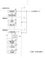
- FIG. 1 is a block diagram showing the overall configuration of an X-ray diagnostic apparatus in the present embodiment.
- FIG. 2 is a block diagram showing a specific configuration of an X-ray fluoroscopic unit included in the X-ray diagnostic apparatus according to the present embodiment.
- the block diagram which shows the mechanism drive part which supplies a drive signal with respect to the various moving mechanism parts and rotation mechanism parts provided in the holding
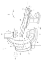
- photography position in the stereoscopic vision imaging mode of this embodiment The figure which shows the structure of the slide movement mechanism part with which the holding
- maintenance apparatus of this embodiment is provided.
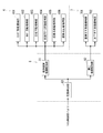
- 6 is a flowchart showing a procedure for generating / displaying image data in the stereoscopic shooting mode of the present embodiment.
- An X-ray diagnostic apparatus includes an X-ray generation unit that generates X-rays irradiated to a subject, an X-ray detection unit that detects X-rays, an X-ray generation unit, and an X-ray A holding unit that holds the detection unit, a holding unit moving unit that is provided in the holding unit, has a rotor, and reciprocates the holding unit in a predetermined range along a predetermined direction by rotational movement in one direction of the rotor; , With.
- the X-ray diagnostic apparatus is suitable for X-ray fluoroscopy in a reciprocating motion mode in which X-ray imaging is repeatedly performed at a plurality of predetermined locations by reciprocating the X-ray imaging system and the above-described predetermined plurality of locations.
- X-ray fluoroscopy is performed in a normal mode (standard imaging mode) for the purpose of specifying an imaging position.
- the holding device included in the X-ray diagnostic apparatus is a slide movement for a normal mode that moves an X-ray generation unit and an X-ray detection unit (imaging system) attached in the vicinity of the end of the C arm in a desired direction at a normal speed.
- a mechanism holding unit moving unit and a function of converting high-speed rotational movement in one predetermined direction into high-speed reciprocating movement, and by reciprocating the above-mentioned imaging system within a predetermined range at a predetermined plurality of locations.
- a slide movement mechanism holding part moving part for a reciprocating motion mode that repeatedly performs X-ray imaging is provided.
- FIGS. 1 is a block diagram showing the overall configuration of the X-ray diagnostic apparatus
- FIGS. 2 and 5 are specific examples of the X-ray fluoroscopic imaging unit, the holding device, and the mechanism driving unit provided in the X-ray diagnostic apparatus. It is a block diagram which shows a structure.
- the X-ray diagnostic apparatus 100 includes an X-ray fluoroscopic imaging unit 1 that generates projection data by X-ray fluoroscopy with respect to a subject 150, and an X-ray fluoroscopic imaging unit 1 to be described later.
- a holding device 6 that holds the ray generation unit 2 and the X-ray detection unit 3 (imaging system) and moves or rotates around the subject 150, and a subject 150 that is provided on the bed 7 and placed on the upper surface thereof X
- the top plate 71 is moved to a position suitable for fluoroscopy.
- the X-ray diagnostic apparatus 100 has a mechanism driving unit 8.
- the mechanism driving unit 8 supplies driving signals to various moving mechanism units and rotation mechanism units provided in the holding device 6 and the bed 7, and an imaging system and a top plate attached to the holding unit of the holding device 6.
- An imaging position suitable for X-ray fluoroscopy in the normal mode (standard imaging mode) and the reciprocating motion mode is set by moving the subject 150 placed on 71.
- the normal mode (hereinafter referred to as a standard shooting mode) is a mode for moving the holding device 6 along a predetermined direction.
- the standard imaging mode the user can move and position the holding device 6 to an arbitrary location, and perform X-ray imaging at the positioned location.
- the reciprocating motion mode is a mode for causing the holding device 6 to reciprocate within a predetermined range along a predetermined direction using the rotational motion of the rotor in one direction.
- the holding device 6 can be reciprocated, and imaging can be performed at a plurality of predetermined locations (imaging positions) for each reciprocation. For this reason, in the reciprocating motion mode, X-ray imaging at a plurality of predetermined locations can be repeated.
- the left-eye image for binocular stereoscopic viewing and the A right-eye image can be acquired.
- the reciprocating motion mode is referred to as a stereoscopic shooting mode.
- the X-ray diagnostic apparatus 100 further generates reference image data based on the projection data in the standard imaging mode generated in the X-ray fluoroscopic imaging unit 1, and binocular stereoscopic vision based on the projection data in the stereoscopic imaging mode.
- the image data generation / storage unit 9 that generates and stores the first image data and the second image data corresponding to the reference image data, the reference image data obtained in the standard imaging mode, and the stereoscopic imaging mode.
- Display unit 10 for performing stereoscopic display by displaying first image data and second image data, selection of a shooting mode, setting of a reference shooting position in standard shooting mode, and setting of a shooting interval in stereoscopic shooting mode
- An operation unit 11 for setting fluoroscopic imaging conditions, inputting various instruction signals, and the like, and a system control unit 12 for comprehensively controlling each of the above-described units.
- the X-ray fluoroscopic imaging unit 1 of the X-ray diagnostic apparatus 100 shown in FIG. 2 two-dimensionally transmits an X-ray generation unit 2 that irradiates the subject 150 with X-rays and an X-ray that has passed through the subject 150.
- An X-ray detector 3 that detects and generates projection data based on the detection result, and a high-voltage generator 4 that generates a high voltage necessary for the X-ray irradiation and supplies the high voltage to the X-ray generator 2. ing.
- the X-ray generation unit 2 includes an X-ray tube 21 that emits X-rays to the subject 150, and an X-ray diaphragm that forms an X-ray weight (cone beam) for the X-rays emitted from the X-ray tube 21.
- a container 22 is provided.
- the X-ray tube 21 is a vacuum tube that generates X-rays, and accelerates electrons emitted from a cathode (filament) by a high voltage to collide with a tungsten anode to generate X-rays.
- the X-ray diaphragm 22 is used for the purpose of reducing the exposure dose to the subject 150 and improving the image quality of the image data, and sets the fluoroscopic region in the subject 150 of the X-rays emitted from the X-ray tube 21.
- a vane and a compensation filter (none of which is shown) for preventing halation by selectively reducing X-rays transmitted through a living tissue having a small amount of absorption are provided.
- the X-ray detector 3 converts the X-rays transmitted through the fluoroscopic region formed by the diaphragm blades of the X-ray diaphragm 22 into signal charges and accumulates them, and accumulates them in the planar detector 31.
- the X-ray detection method includes a method of directly converting X-rays into signal charges and a method of converting X-rays into light and then converting them into signal charges. In the present embodiment, the former will be described as an example. Good. Further, instead of the flat detector 31, X-ray I.D. I. A method using (image intensifier) may be used.
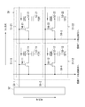
- the flat detector 31 of the X-ray detection unit 3 is configured by two-dimensionally arranging minute detection elements 51 in the column direction and the line direction, and each of the detection elements 51 (51-11, 51, 51-12, 51-21, 51-22) are photoelectric films 52 (52-11, 52-12, 52-21, 52-22) that detect X-rays and generate signal charges according to the incident X-ray dose.
- a charge storage capacitor 53 (53-11, 53-12, 53-21, 53-22) for storing the signal charge generated in the photoelectric film 52, and a signal charge stored in the charge storage capacitor 53 for a predetermined amount.
- a TFT (thin film transistor) 54 (54-11, 54-12, 54-21, 54-22) that reads out at timing is provided.
- the flat panel detector 31 used for actual X-ray fluoroscopy has many detection elements 51 arranged in the column direction and in the horizontal direction. It is configured by arranging in the line direction.
- the gate driver 32 reads the signal charge generated in the photoelectric film 52 of the detection element 51 by the X-ray irradiation and accumulated in the charge storage capacitor 53 to the signal line 58 (58-1, 58).
- a driving pulse for reading is supplied via -2).
- the projection data generation unit 33 converts the signal charge read from the flat detector 31 into a voltage, a charge / voltage converter 331, and converts the output of the charge / voltage converter 331 into a digital signal.
- a parallel / serial converter 333 that converts the data elements of the projection data read out in parallel in units of lines from the flat detector 31 and converted into digital data into a time-series signal.
- the charge / voltage converter 331 and the A / D converter 332 have the same number of channels as the signal output lines 59 (59-1, 59-2) of the flat panel detector 31 shown in FIG. .
- the high voltage generation unit 4 of the X-ray fluoroscopic unit 1 applies a high voltage between the anode and the cathode in order to accelerate the thermal electrons generated from the cathode of the X-ray tube 21 provided in the X-ray generation unit 2.
- the X-ray tube 21 is controlled by controlling the application voltage, application time, application timing, and the like of the high-voltage generator 42 based on the voltage generator 42 and the X-ray irradiation conditions of the fluoroscopic imaging conditions supplied from the system control unit 12.
- an X-ray control unit 41 for setting the tube current, tube voltage, X-ray irradiation time, X-ray irradiation timing, irradiation repetition period, and the like.
- FIG. 4 the holding device 6 having the C-arm (holding tool) 61 and the like 150 to which the X-ray generation unit 2 and the X-ray detection unit 3 (imaging system) are attached in the vicinity of the end thereof and the subject 150 are placed.
- a bed 7 having a top plate 71 is shown.
- the body axis direction (longitudinal direction of the top plate 71) of the subject 150 is the y direction, and the direction perpendicular to the floor surface 160 on which the holding device 6 and the bed 7 are installed.
- the z direction, the y direction, and the direction orthogonal to the z direction are defined as the x direction.
- FIG. 5 is a block diagram showing an example of the configuration of various moving mechanism sections and rotating mechanism sections provided on the holding device 6 and the bed 7 and a mechanism driving section 8 for supplying drive signals to these mechanism sections.
- FIG. 5 is a block diagram showing an example of the configuration of various moving mechanism sections and rotating mechanism sections provided on the holding device 6 and the bed 7 and a mechanism driving section 8 for supplying drive signals to these mechanism sections.
- the holding device 6 includes a C arm 61, an arm holder 62, an arm column 63, and a floor turning arm 64.
- One end of the floor turning arm 64 is attached so as to be rotatable about the floor rotation axis z1 perpendicular to the floor surface 160 in the direction of the arrow d.
- an arm column 63 having an arm column rotation axis z2 parallel to the z direction is attached to the other end of the floor turning arm 64 so as to be rotatable in the direction of the arrow c.
- an arm holder 62 is attached to the side surface of the arm support 63 so as to be rotatable in the direction of the arrow b around the arm main rotation axis z3 parallel to the y direction.
- the C-arm 61 mounted with the X-ray generator 2 and the X-ray detector 3 facing each other in the vicinity of the end slides in the direction of the arrow a about the arm slide center axis z4. It is attached movably.
- the X-ray detection unit 3 of the imaging system mounted in the vicinity of the end of the C arm 61 can be moved in the direction of the arrow e.
- the X-ray detector 3 is attached to the movable diaphragm 22 provided in the X-ray generator 2 so as to be rotatable about the imaging system rotation axis z5 in the direction of arrow f.
- each of the above units constituting the holding device 6 includes a slide moving mechanism unit (holding unit moving unit) 601 that slides the C arm 61 in the direction a about the arm slide central axis z4. , A holder rotation mechanism unit 602 that rotates the arm holder 62 in the b direction around the arm main rotation axis z3, and a column rotation mechanism unit 603 that rotates the arm column 63 in the c direction around the arm column rotation axis z2.
- the bed 7 moves the top plate 71 on which the subject 150 is placed vertically in the h direction (z direction) and the vertical direction moving mechanism unit 701 and the top plate 71 in the longitudinal direction ga (y direction) or the lateral direction gb ( A horizontal movement mechanism unit 702 that slides in the x direction) is provided.
- the imaging system can be set to a position suitable for X-ray fluoroscopy of the subject 150 placed on the top 71.
- the above-described slide moving mechanism unit (holding unit moving unit) 601 is driven to reciprocately slide the C arm 61 on which the imaging system is mounted within a predetermined angle range.
- the above-described slide moving mechanism unit (holding unit moving unit) 601 is driven to reciprocately slide the C arm 61 on which the imaging system is mounted within a predetermined angle range.
- the mechanism driving unit 8 supplies a driving signal to the moving mechanism unit and the rotating mechanism unit provided in the holding device 6 in order to move the imaging system around the subject 150.
- a drive control unit 83 that controls the device mechanism drive unit 81 and the bed mechanism drive unit 82 is provided.
- the mechanism driving unit 8 in the standard photographing mode supplies driving signals to various moving mechanism units and rotating mechanism units provided in the holding device 6 and the bed 7 to move the C arm 61 and the top plate 71.
- the imaging system attached in the vicinity of the end of the C-arm 61 is arranged at a reference photographing position suitable for collecting reference image data.
- the holding device mechanism driving unit 81 of the mechanism driving unit 8 in the stereoscopic shooting mode drives the slide movement mechanism unit 601 of the holding device 6 to perform the reciprocating slide movement of the C arm 61 within a predetermined angle range at high speed.
- the imaging system mounted in the vicinity of the end of the C-arm 61 is arranged at the first and second imaging positions suitable for binocular stereoscopic vision.
- first shooting position from which the first image data is collected and the second shooting position from which the second image data is collected are usually set around the reference shooting position set in the standard shooting mode.
- FIG. 5 shows the configuration of various moving mechanism sections and rotating mechanism sections provided on the holding device 6 and the bed 7 and the mechanism driving section 8 for supplying drive signals to these mechanism sections.
- a slide moving mechanism 601 that slides the C arm 61 along the traveling direction is provided at the joint between the C arm 61 and the arm holder 62 of the holding device 6 shown in FIG. Is provided with a holder turning mechanism 602 for turning the arm holder 62 in the direction b.
- a column rotating mechanism 603 for rotating the arm column 63 in the c direction is provided at a joint portion between the arm column 63 and the floor turning arm 64, and a portion between the floor turning arm 64 and the floor surface 160 is provided at the joint portion.
- a floor turning arm turning mechanism 604 for turning the floor turning arm 64 in the d direction is provided.
- An imaging system moving mechanism 605 that moves the imaging system in the e direction and an imaging system rotation mechanism 606 that rotates the imaging system in the f direction are joined to the joint between the end of the C arm 61 and the imaging system. Is provided.
- the vertical movement mechanism 701 that moves the top plate 71 on which the subject 150 is placed in the h direction and the top plate 71 slide in the longitudinal direction (ga direction) or the lateral direction (gb direction).
- a horizontal movement mechanism unit 702 is provided for movement.
- a drive signal generated by the holding device mechanism drive unit 81 based on a drive control signal supplied from the drive control unit 83 of the mechanism drive unit 8 is supplied to each.
- the drive signal generated by the bed mechanism drive unit 82 based on the drive control signal supplied from the drive control unit 83 is supplied to the vertical direction movement mechanism unit 701 and the horizontal direction movement mechanism unit 702 of the bed 7.
- the mechanism drive unit 8 supplies the above-described drive signals to various moving mechanism units and rotation mechanism units provided in the holding device 6 and the bed 7 and is attached in the vicinity of the end of the C arm 61.
- the reference imaging position in the standard imaging mode and the first imaging position and the second imaging position in the stereoscopic imaging mode are set.
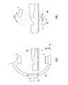
- FIG. 6 shows the reciprocal slide movement of the C-arm 61 by the slide movement mechanism unit 601 of the holding device 6 and the first photographing position and the second photographing position in the stereoscopic photographing mode set by this reciprocating sliding movement. It explains using.
- FIG. 6 (6A) shows the direction (arrow) of the reciprocating slide movement in the stereoscopic imaging mode of the C-arm 61 in which the X-ray detector 3 is attached near the upper end and the X-ray generator 2 is attached near the lower end.
- FIG. 6 (6B) shows the first photographing position Ra and the second photographing position Rb suitable for binocular stereoscopic vision set at this time.
- the X-ray generation unit 2 and the X-ray detection unit 3 (imaging system) It will reciprocate at high speed with the C-arm 61 around 150.
- the first photographing position Ra and the second photographing position Rb are set at the turning point of the high-speed reciprocating movement separated by a predetermined photographing interval ⁇ d.
- the positions of the X-ray generation unit 2 that irradiates the subject 150 with X-rays for fluoroscopy / imaging are defined as the first imaging position Ra and the second imaging position Rb, but are not limited thereto. .
- the slide moving mechanism unit 601 has a belt 611 attached along the side surface of the C arm 61 and a rotation that slides the C arm 61 in a predetermined direction by moving the belt 611.
- a pulley 613a that changes the traveling direction of the belt 611 from the side surface of the C arm 61 to the side surface of the rotating unit 612
- a pulley 613b that changes the traveling direction from the side surface of the rotating unit 612 to the side surface of the C arm 61.
- the slide moving mechanism 601 includes a roller 614 as a rotor that rotates at a high speed at a predetermined speed, a mounting portion 615 that can be attached to and detached from the side surface of the C-arm 61 by a locking means such as an electromagnet, and one end portion. Is provided with a link mechanism 610 having an arm 616 that is rotatably attached in the vicinity of the peripheral portion of the roller 614 and whose other end is rotatably attached to the mounting portion 615.
- the holding device mechanism driving unit 81 of the mechanism driving unit 8 When the standard photographing mode is selected by the operation unit 11, the holding device mechanism driving unit 81 of the mechanism driving unit 8 generates the drive signal generated based on the drive control signal supplied from the drive control unit 83. To the slide movement mechanism 601 and the lock state between the mounting portion 615 of the link mechanism 610 and the side surface of the C-arm 61 is released as shown in FIG.
- the holding device mechanism driving unit 81 rotates the rotating unit 612 in a predetermined direction with the belt 611 attached to the side surface of the C arm 61 in a tensioned state by moving the rotating unit 612 rightward. Then, the C-arm 61 connected via the belt 611 is slid along the traveling direction along with the rotation of the rotation unit 612, so that the imaging system attached in the vicinity of the end of the C-arm 61 (see FIG. 4). ) Moves. As described above, in the standard imaging mode, the user can move and position the holding device 6 to any position via the operation unit 11 or manually.
- the holding device mechanism driving unit 81 of the mechanism driving unit 8 supplies the drive signal generated in the same manner as in the case of the standard shooting mode to the slide moving mechanism unit 601, and FIG. As shown in (7B), the rotating part 612 is moved to the left and the belt 611 attached to the side surface of the C arm 61 is in a relaxed state, thereby releasing the connection state with the C arm 61.
- the holding device mechanism driving unit 81 mounts the mounting unit 615 of the link mechanism 610 on the side surface of the C arm 61, and then rotates the roller 614 at a high speed, thereby rapidly moving the C arm 61 in a predetermined angular range ⁇ . Then, the imaging system attached in the vicinity of the end of the C arm 61 is reciprocated at high speed between the first imaging position and the second imaging position suitable for the stereoscopic imaging mode.
- a rotation mechanism such as a motor for rotating the rotation unit 612 and the roller 614 is normally provided inside the rotation unit 612 or the roller 614, but may be provided separately.
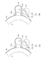
- FIG. 8 (8A) to 8 (8C) show a state in which the mounting portion 615 mounted on the side surface of the C-arm 61 reciprocates at high speed as the roller 614 rotates in one direction in the stereoscopic shooting mode. Is. For example, when the connecting portion between the roller 614 that rotates at a high speed in the counterclockwise direction and the arm 616 moves to Pa in FIG. 8 (8 A), the mounting portion 615 moves to the first photographing position along the traveling direction of the C arm 61. When it moves to the corresponding position Sa and the connecting portion moves to Pc in FIG. 8 (8C), it moves to the position Sc corresponding to the second imaging position.
- the mounting portion 615 of the link mechanism 610 mounted on the side surface of the C arm 61 repeats high-speed reciprocation between the position Sa and the position Sc as the roller 614 rotates in one direction at a high speed.
- the high-speed reciprocating movement of the mounting portion 615 the reciprocating slide movement along the traveling direction is performed at a high speed.
- the imaging system attached in the vicinity of the end of the C arm 61 is disposed at the first shooting position suitable for the stereoscopic shooting mode.
- the mounting unit 615 reaches the position Sc the above-described imaging system is disposed at the second imaging position.
- the movement direction switching points (return points) Sa and Sc in the reciprocating motion are set as the first imaging position and the second imaging position, respectively.
- the first imaging position and the second imaging position only have to be located within a predetermined range where the reciprocating motion is performed, and are not limited to the switching points of the motion direction in the reciprocating motion.
- the image data generation / storage unit 9 includes an image data generation unit 91 and image data storage units 92a and 92b.
- the image data generation unit 91 includes a projection data storage unit (not shown). The data elements of the projection data supplied in time series from the projection data generation unit 33 included in the X-ray detection unit 3 of the X-ray fluoroscopic imaging unit 1 are described above.
- the two-dimensional image data is generated by sequentially storing in the projection data storage unit.
- the image data generation unit 91 generates first image data based on the projection data supplied from the projection data generation unit 33 during X-ray fluoroscopy at the first imaging position.
- Second image data is generated based on the projection data supplied from the projection data generation unit 33 during X-ray fluoroscopy at the second imaging position. Then, the image data generation unit 91 stores the first image data in the image data storage unit 92a, and stores the second image data in the image data storage unit 92b.
- the display unit 10 has a function of providing binocular parallax without performing parallel display without causing a medical worker who operates the X-ray diagnosis apparatus 100 (hereinafter referred to as an operator) to wear special glasses.
- the first image data read from the image data storage unit 92a of the image data generation / storage unit 9 and the second image data read out from the image data storage unit 92b.
- the monitor has a function of displaying in parallel.
- a monitor that gives binocular parallax to the operator without requiring parallel display when expressed as “autostereoscopic display as display unit 10” is shown. Further, when the expression “display unit 10” is simply used, a monitor capable of displaying in parallel the right-eye / left-eye images as shown in FIG. 9 is shown.
- the autostereoscopic display that has the function of giving binocular parallax without requiring the operator to put on special glasses is a mechanism that allows separate light beams to enter the left and right eyes using various methods such as the parallax barrier method and the lenticular lens method.
- various methods such as the parallax barrier method and the lenticular lens method.
- the display unit 10 parallels the first image data read from the image data storage unit 92a and the second image data read from the image data storage unit 92b, for example, at a data interval suitable for autostereoscopic binocular vision.
- a display data generation unit that generates display data by arranging the display data, a conversion processing unit that performs conversion processing such as D / A conversion and television format conversion on the display data, and a monitor that displays the converted display data (Both not shown).
- the data interval between the first image data and the second image data displayed on the display unit 10 is set based on a shooting interval ⁇ d set in advance by the operation unit 11 described later.
- the operation unit 11 is an interactive interface including operation / input devices such as a display panel, a keyboard, a trackball, a joystick, and a mouse.
- the operation unit 11 is used to input subject information and perform imaging modes (standard imaging mode / stereoscopic imaging mode). Selection, setting of fluoroscopic imaging conditions including X-ray irradiation conditions (tube current, tube voltage, X-ray irradiation time, X-ray irradiation period, X-ray irradiation timing, etc.), setting of image data generation conditions, reference imaging in standard imaging mode Setting of the position, setting of the shooting interval ⁇ d in the stereoscopic shooting mode, input of various instruction signals, and the like are performed.
- the system control unit 12 includes a CPU and an input information storage unit (not shown). Various types of information input / set / selected in the operation unit 11 are stored in the input information storage unit.
- the CPU controls the above-described units of the X-ray diagnostic apparatus 100 based on the above-described information read from the input information storage unit, so that the X in the standard imaging mode for the fluoroscopic region of the subject 150 is obtained.
- Reference image data is collected by performing fluoroscopy and a reference photographing position from which the reference image data is obtained is set. Further, the first photographing suitable for the stereoscopic photographing mode set around the reference photographing position is performed. Generation and display of first image data and second image data corresponding to binocular stereoscopic vision are executed by reciprocating the imaging system at high speed between the position and the second imaging position.
- the first image data generated for the left eye and the second image data generated for the right eye are parallel to the monitor of the display unit 10 at a predetermined data interval. The operator can directly observe the image data displayed on the monitor without using special deflection glasses or the like.
- first image data Ima and second image data Imb displayed in parallel at a predetermined data interval ⁇ on the monitor of the display unit 10.
- the focal point Fo (not shown) of the left eye Aa and the right eye Ab
- the first image data Ima and the second image data Imb are left as shown in FIG. 9 (9B).
- the binocular stereoscopic vision of the naked eye method to which this embodiment is applied may be either the parallel method or the intersection method. .
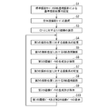
- the X-ray fluoroscopic imaging unit 1 of the X-ray diagnostic apparatus 100 Prior to the collection of the first image data and the second image data corresponding to the binocular stereopsis, the X-ray fluoroscopic imaging unit 1 of the X-ray diagnostic apparatus 100 is supplied from the operation unit 11 via the system control unit 12. X-ray fluoroscopy in the standard imaging mode is performed on the subject 150 using an imaging system that moves together with the C arm 61 in accordance with the holding unit movement instruction signal. Then, the operator adjusts the position of the imaging system while observing the image data obtained at this time, thereby collecting reference image data and setting a reference photographing position from which the reference image data is obtained (step in FIG. 10). S1).
- the operator uses the operation / input device provided in the operation unit 11 to select the stereoscopic shooting mode (step S2 in FIG. 10).
- the drive control unit 83 of the mechanism drive unit 8 that has received the above selection information via the system control unit 12 generates a drive control signal for performing the reciprocating slide movement of the C arm 61 at a high speed, and the holding device mechanism.
- the holding device mechanism drive unit 81 supplies the drive unit 81 with various drive signals generated based on the above-described drive control signal to the slide movement mechanism unit 601 of the holding device 6.
- the mounting portion 615 of the link mechanism 610 is mounted on the side surface of the C arm 61 (step S3 in FIG. 10).
- the roller 614 of the link mechanism 610 is rotated at a high speed in a predetermined direction to move the C arm 61 at a high speed along the traveling direction, and the imaging system attached in the vicinity of the end of the C arm 61 is set in the standard shooting mode.
- the reference shooting position is moved to the first shooting position suitable for the stereoscopic shooting mode (step S4 in FIG. 10).
- the system control unit 12 sets the X-ray irradiation conditions read from the fluoroscopic instruction signal and its own input information storage unit to the X-rays of the high voltage generation unit 4.
- the X-ray control unit 41 supplied to the control unit 41 and receiving this instruction signal controls the high voltage generator 42 based on the above-described X-ray irradiation conditions, thereby controlling the X-ray tube 21 of the X-ray generation unit 2.
- a predetermined high voltage is applied.
- the X-ray tube 21 to which the high voltage is applied irradiates the fluoroscopic region of the subject 150 via the X-ray restrictor 22 and X-rays transmitted through the fluoroscopic region are provided behind the X-ray. It is detected by the flat detector 31 of the line detector 3.
- the photoelectric film 52 of the detection elements 51 arranged in a two-dimensional manner in the flat detector 31 detects X-rays transmitted through the subject 150 and accumulates signal charges proportional to the amount of transmission in the charge storage capacitor 53. .
- the gate driver 32 sequentially reads out the signal charges stored in the charge storage capacitor 53 by supplying a drive pulse to the TFT 54 of the flat panel detector 31.
- the read signal charges are converted into voltages by the charge / voltage converter 331 of the projection data generation unit 33, converted into digital signals by the A / D converter 332, and then buffer memory of the parallel / serial converter 333.
- the parallel / serial converter 333 serially reads out the data elements of the projection data stored in its own buffer memory line by line, and stores the projection data in the image data generation unit 91 included in the image data generation / storage unit 9.
- the first image data is generated in the projection data storage unit by sequentially storing in the projection data storage unit.
- the obtained first image data is stored in the image data storage unit 92a of the image data generation / storage unit 9 (step S6 in FIG. 10).
- the C-arm 61 is moved at a high speed in the opposite direction by continuously rotating the roller 614 at a high speed.
- the imaging system attached in the vicinity of the end of the arm 61 is disposed at the second imaging position suitable for the stereoscopic imaging mode (step S7 in FIG. 10).
- step S8 and step S9 in FIG. 10 When the arrangement of the imaging system with respect to the second imaging position is completed, X-ray fluoroscopy is performed at the second imaging position by the same procedure as in step S5 described above, and the image data generation / storage unit 9 Second image data is generated based on projection data obtained by fluoroscopy. Then, the obtained second image data is stored in the image data storage unit 92b of the image data generation / storage unit 9 (step S8 and step S9 in FIG. 10).
- the display unit 10 displays the first image data and the second image data. Display that gives binocular parallax to the operator based on the image data is performed.
- the display unit 10 sets the first image data read from the image data storage unit 92a and the second image data read from the image data storage unit 92b to, for example, the shooting interval ⁇ d. The data is displayed in parallel at a data interval ⁇ suitable for binocular stereoscopic vision set based on the setting (step S10 in FIG. 10).
- the slide moving mechanism unit 601 of the present modification includes a belt 611 attached along the side surface of the C arm 61, and a rotation that moves the C arm 61 in a predetermined direction by moving the belt 611.
- a pulley 613a that changes the traveling direction of the belt 611 from the side surface of the C arm 61 to the side surface of the rotating unit 612
- a pulley 613b that changes the traveling direction from the side surface of the rotating unit 612 to the side surface of the C arm 61.
- the slide moving mechanism 601 is detachable from the side surface of the C arm 61 by a cam 617 as a rotor having an elliptical cross section and rotating at a predetermined speed and a locking means such as an electromagnet.
- a cam mechanism 619 having a mounting portion 615a.
- the cam 617 and the mounting portion 615a are in contact with each other by, for example, gravity or magnetic force.
- the rotation center of the cam 617 is fixed at a predetermined position.
- the mounting portion 615a slides along the outer periphery of the cam 617 according to the rotation of the cam 617.
- the holding device mechanism driving unit 81 of the mechanism driving unit 8 When the standard photographing mode is selected in the operation unit 11, the holding device mechanism driving unit 81 of the mechanism driving unit 8 generates a drive signal generated based on the drive control signal supplied from the drive control unit 83. To the slide movement mechanism 601 and the lock state between the mounting portion 615a of the cam mechanism 619 and the side surface of the C-arm 61 is released as shown in FIG.
- the holding device mechanism driving unit 81 rotates the belt 611 attached to the side surface of the C arm 61 in a predetermined state by moving the rotating unit 612 in the right direction. Then, the C-arm 61 connected via the belt 611 is slid along the traveling direction, so that the imaging system attached in the vicinity of the end of the C-arm 61 is moved to a reference shooting position suitable for the standard shooting mode. Move.
- the holding device mechanism driving unit 81 of the mechanism driving unit 8 supplies the drive signal generated in the same manner as in the case of the standard shooting mode to the slide moving mechanism unit 601, and FIG. As shown in (11B), the rotating portion 612 is moved to the left to release the belt 611 attached to the side surface of the C arm 61, thereby releasing the connection state with the C arm 61.
- the holding device mechanism driving unit 81 mounts the mounting portion 615a of the cam mechanism 619 on the side surface of the C arm 61, and then rotates the cam 617 at a high speed, thereby reciprocating the C arm 61 in a predetermined angular range ⁇ at high speed. Then, the imaging system attached in the vicinity of the end of the C arm 61 is reciprocated at high speed between the first imaging position and the second imaging position suitable for the stereoscopic imaging mode.
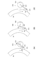
- 12 (12A) and 12 (12B) show a state in which the mounting portion 615a mounted on the side surface of the C arm 61 reciprocates at high speed as the cam 617 rotates at high speed in the stereoscopic shooting mode.
- the central portion of the mounting portion 615a is the position Soa corresponding to the first shooting position along the traveling direction of the C-arm 61.
- the cam 617 moves to a position Sob corresponding to the second shooting position.
- the mounting portion 615a of the cam mechanism 619 mounted on the side surface of the C arm 61 repeats high-speed reciprocation between the position Soa and the position Sob along with the high-speed rotation of the cam 617.
- the reciprocating sliding movement along the traveling direction is performed at a high speed by the high-speed reciprocating movement of 615a.
- the imaging system mounted near the end of the C arm 61 is disposed at the first shooting position suitable for the stereoscopic shooting mode and mounted.
- the unit 615a reaches Sob, the above-described imaging system is arranged at the second imaging position.
- the time resolution is achieved by reciprocating the imaging system used for X-ray fluoroscopy within a predetermined range at high speed. It is possible to collect binocular stereoscopic image data excellent in the above.
- the moving mechanism unit corresponding to the standard shooting mode and the moving mechanism unit corresponding to the stereoscopic shooting mode based on the selection information of the shooting mode, it is possible to obtain good image data in each shooting mode.
- the shooting position in the stereoscopic shooting mode is set based on the image data in the standard shooting mode, the accurate shooting position can be set easily and in a short time. This not only improves the inspection efficiency and diagnostic accuracy, but also reduces the burden on the operator.
- this indication is not limited to the above-mentioned embodiment and its modification, and it can change and can carry out further.
- the C arm 61 is slid at a high speed by driving the slide movement mechanism 601 of the holding device 6 has been described.
- the holder rotation mechanism 602 is driven.
- the C-arm 61 fixed to the arm holder 62 may be rotated in the b direction around the arm main rotation axis z3 to set a photographing position suitable for binocular stereoscopic vision.
- the second imaging position at the second imaging position is repeated.
- the second image data stored in the image data storage unit 92b and the first image data already collected and stored in the image data storage unit 92a are used.
- the first image data stored in the image data storage unit 92a may generate a new display data by using.
- an imaging position suitable for binocular stereoscopic vision may be set by reciprocating the imaging system attached to another holding unit such as an ⁇ arm at high speed.
- each unit included in the X-ray diagnostic apparatus 100 may be, for example, a computer including a CPU, a RAM, a magnetic storage device, an input device, a display device, and the like used as hardware.
- the system control unit 12 of the X-ray diagnostic apparatus 100 can realize various functions by causing a processor such as a CPU mounted on the computer to execute a predetermined control program.
- the above-described control program may be installed in advance in the computer, or may be stored in a computer-readable storage medium or installed in the computer of the control program distributed via the network. .
Landscapes
- Health & Medical Sciences (AREA)
- Life Sciences & Earth Sciences (AREA)
- Engineering & Computer Science (AREA)
- Medical Informatics (AREA)
- Radiology & Medical Imaging (AREA)
- Molecular Biology (AREA)
- Biophysics (AREA)
- Nuclear Medicine, Radiotherapy & Molecular Imaging (AREA)
- Optics & Photonics (AREA)
- Pathology (AREA)
- Physics & Mathematics (AREA)
- Biomedical Technology (AREA)
- Heart & Thoracic Surgery (AREA)
- High Energy & Nuclear Physics (AREA)
- Surgery (AREA)
- Animal Behavior & Ethology (AREA)
- General Health & Medical Sciences (AREA)
- Public Health (AREA)
- Veterinary Medicine (AREA)
- Apparatus For Radiation Diagnosis (AREA)
- Human Computer Interaction (AREA)
Priority Applications (2)
| Application Number | Priority Date | Filing Date | Title |
|---|---|---|---|
| CN201480007480.2A CN104994789A (zh) | 2013-02-08 | 2014-02-07 | X射线诊断装置 |
| US14/797,729 US20150313564A1 (en) | 2013-02-08 | 2015-07-13 | X-ray diagnostic apparatus |
Applications Claiming Priority (2)
| Application Number | Priority Date | Filing Date | Title |
|---|---|---|---|
| JP2013-023583 | 2013-02-08 | ||
| JP2013023583A JP2014151008A (ja) | 2013-02-08 | 2013-02-08 | X線診断装置 |
Related Child Applications (1)
| Application Number | Title | Priority Date | Filing Date |
|---|---|---|---|
| US14/797,729 Continuation US20150313564A1 (en) | 2013-02-08 | 2015-07-13 | X-ray diagnostic apparatus |
Publications (1)
| Publication Number | Publication Date |
|---|---|
| WO2014123219A1 true WO2014123219A1 (ja) | 2014-08-14 |
Family
ID=51299809
Family Applications (1)
| Application Number | Title | Priority Date | Filing Date |
|---|---|---|---|
| PCT/JP2014/052899 Ceased WO2014123219A1 (ja) | 2013-02-08 | 2014-02-07 | X線診断装置 |
Country Status (4)
| Country | Link |
|---|---|
| US (1) | US20150313564A1 (enExample) |
| JP (1) | JP2014151008A (enExample) |
| CN (1) | CN104994789A (enExample) |
| WO (1) | WO2014123219A1 (enExample) |
Families Citing this family (3)
| Publication number | Priority date | Publication date | Assignee | Title |
|---|---|---|---|---|
| US11241206B2 (en) * | 2017-03-21 | 2022-02-08 | Canon Medical Systems Corporation | X-ray imaging apparatus |
| JP7129963B2 (ja) * | 2019-09-30 | 2022-09-02 | 富士フイルム株式会社 | 放射線撮影装置 |
| JP2023077591A (ja) * | 2021-11-25 | 2023-06-06 | キヤノンメディカルシステムズ株式会社 | X線診断装置 |
Citations (6)
| Publication number | Priority date | Publication date | Assignee | Title |
|---|---|---|---|---|
| JPH0497151U (enExample) * | 1991-01-18 | 1992-08-21 | ||
| JPH09512623A (ja) * | 1995-02-28 | 1997-12-16 | ジンテーズ アクチエンゲゼルシャフト,クール | 回転運動を往復運動に変換する伝動装置 |
| JPH1033516A (ja) * | 1996-07-26 | 1998-02-10 | Takashi Oe | X線診断装置 |
| JP2000000233A (ja) * | 1999-05-13 | 2000-01-07 | Shimadzu Corp | X線撮影装置 |
| JP2003047609A (ja) * | 2001-08-03 | 2003-02-18 | Hitachi Medical Corp | X線撮影装置 |
| JP2005027914A (ja) * | 2003-07-07 | 2005-02-03 | Shimadzu Corp | Cアーム形x線装置 |
Family Cites Families (4)
| Publication number | Priority date | Publication date | Assignee | Title |
|---|---|---|---|---|
| JPH0719312A (ja) * | 1993-06-29 | 1995-01-20 | Soken:Kk | 回転運動を湾曲往復運動に変える方法及びその装置 |
| KR101266893B1 (ko) * | 2009-06-25 | 2013-05-24 | 가부시끼가이샤 요시다세이사쿠쇼 | X선 촬영장치 |
| JP2012253757A (ja) * | 2011-05-31 | 2012-12-20 | Fujifilm Corp | 立体視画像表示装置およびその動作方法 |
| JP6125154B2 (ja) * | 2012-05-09 | 2017-05-10 | 東芝メディカルシステムズ株式会社 | X線撮影装置及び医用画像処理装置 |
-
2013
- 2013-02-08 JP JP2013023583A patent/JP2014151008A/ja active Pending
-
2014
- 2014-02-07 CN CN201480007480.2A patent/CN104994789A/zh active Pending
- 2014-02-07 WO PCT/JP2014/052899 patent/WO2014123219A1/ja not_active Ceased
-
2015
- 2015-07-13 US US14/797,729 patent/US20150313564A1/en not_active Abandoned
Patent Citations (6)
| Publication number | Priority date | Publication date | Assignee | Title |
|---|---|---|---|---|
| JPH0497151U (enExample) * | 1991-01-18 | 1992-08-21 | ||
| JPH09512623A (ja) * | 1995-02-28 | 1997-12-16 | ジンテーズ アクチエンゲゼルシャフト,クール | 回転運動を往復運動に変換する伝動装置 |
| JPH1033516A (ja) * | 1996-07-26 | 1998-02-10 | Takashi Oe | X線診断装置 |
| JP2000000233A (ja) * | 1999-05-13 | 2000-01-07 | Shimadzu Corp | X線撮影装置 |
| JP2003047609A (ja) * | 2001-08-03 | 2003-02-18 | Hitachi Medical Corp | X線撮影装置 |
| JP2005027914A (ja) * | 2003-07-07 | 2005-02-03 | Shimadzu Corp | Cアーム形x線装置 |
Also Published As
| Publication number | Publication date |
|---|---|
| CN104994789A (zh) | 2015-10-21 |
| JP2014151008A (ja) | 2014-08-25 |
| US20150313564A1 (en) | 2015-11-05 |
Similar Documents
| Publication | Publication Date | Title |
|---|---|---|
| EP2250965B1 (en) | Image acquisition method, device and radiography system | |
| CN101953694B (zh) | 医用和工业用x射线实时立体成像装置 | |
| JP6334898B2 (ja) | コリメータ、及び該コリメータを備えた計算機式断層写真法(ct)システム | |
| JP5268340B2 (ja) | X線撮影装置及びx線撮影方法 | |
| CN103517674B (zh) | X射线摄影装置、医用图像处理装置、x射线摄影方法以及医用图像处理方法 | |
| JP5436301B2 (ja) | 放射線撮影装置、及び放射線撮影システム | |
| US20150085975A1 (en) | X-ray diagnostic apparatus, medical image processing apparatus, and image processing method | |
| CN104994790A (zh) | X射线诊断装置 | |
| JP2013013651A (ja) | X線撮影装置およびそのキャリブレーション方法 | |
| WO2014123219A1 (ja) | X線診断装置 | |
| CN201814585U (zh) | 医用和工业用x射线实时立体成像装置 | |
| JP2009153589A (ja) | X線撮影装置 | |
| JP2014028123A (ja) | X線診断装置 | |
| JP3780217B2 (ja) | 放射線撮影装置 | |
| JP5475830B2 (ja) | X線ct装置 | |
| JP2003038477A (ja) | X線撮影装置 | |
| JP2012189560A (ja) | 放射線透視検査装置 | |
| JP5537520B2 (ja) | X線ct装置 | |
| JP2015047392A (ja) | X線断層撮影装置 | |
| US20180308218A1 (en) | Non-parallax panoramic imaging for a fluoroscopy system | |
| JP2013022155A (ja) | 医用画像診断装置及び医用画像処理方法 | |
| JP5036915B2 (ja) | X線ct装置 | |
| JP2015109893A (ja) | X線診断装置 | |
| JP6048343B2 (ja) | 放射線断層撮影装置 | |
| JP2013202058A (ja) | 放射線撮影表示システムおよびその方法 |
Legal Events
| Date | Code | Title | Description |
|---|---|---|---|
| 121 | Ep: the epo has been informed by wipo that ep was designated in this application |
Ref document number: 14749009 Country of ref document: EP Kind code of ref document: A1 |
|
| NENP | Non-entry into the national phase |
Ref country code: DE |
|
| 122 | Ep: pct application non-entry in european phase |
Ref document number: 14749009 Country of ref document: EP Kind code of ref document: A1 |