WO2014119735A1 - 処理装置、噴射処理方法および電極材料の製造方法 - Google Patents
処理装置、噴射処理方法および電極材料の製造方法 Download PDFInfo
- Publication number
- WO2014119735A1 WO2014119735A1 PCT/JP2014/052280 JP2014052280W WO2014119735A1 WO 2014119735 A1 WO2014119735 A1 WO 2014119735A1 JP 2014052280 W JP2014052280 W JP 2014052280W WO 2014119735 A1 WO2014119735 A1 WO 2014119735A1
- Authority
- WO
- WIPO (PCT)
- Prior art keywords
- mode
- pressure
- exhaust
- main chamber
- processing apparatus
- Prior art date
- Legal status (The legal status is an assumption and is not a legal conclusion. Google has not performed a legal analysis and makes no representation as to the accuracy of the status listed.)
- Ceased
Links
Images

Classifications
-
- H—ELECTRICITY
- H01—ELECTRIC ELEMENTS
- H01M—PROCESSES OR MEANS, e.g. BATTERIES, FOR THE DIRECT CONVERSION OF CHEMICAL ENERGY INTO ELECTRICAL ENERGY
- H01M4/00—Electrodes
- H01M4/02—Electrodes composed of, or comprising, active material
- H01M4/04—Processes of manufacture in general
- H01M4/0402—Methods of deposition of the material
- H01M4/0419—Methods of deposition of the material involving spraying
-
- B—PERFORMING OPERATIONS; TRANSPORTING
- B05—SPRAYING OR ATOMISING IN GENERAL; APPLYING FLUENT MATERIALS TO SURFACES, IN GENERAL
- B05B—SPRAYING APPARATUS; ATOMISING APPARATUS; NOZZLES
- B05B1/00—Nozzles, spray heads or other outlets, with or without auxiliary devices such as valves, heating means
- B05B1/005—Nozzles or other outlets specially adapted for discharging one or more gases
-
- B—PERFORMING OPERATIONS; TRANSPORTING
- B05—SPRAYING OR ATOMISING IN GENERAL; APPLYING FLUENT MATERIALS TO SURFACES, IN GENERAL
- B05D—PROCESSES FOR APPLYING FLUENT MATERIALS TO SURFACES, IN GENERAL
- B05D1/00—Processes for applying liquids or other fluent materials
- B05D1/02—Processes for applying liquids or other fluent materials performed by spraying
-
- C—CHEMISTRY; METALLURGY
- C23—COATING METALLIC MATERIAL; COATING MATERIAL WITH METALLIC MATERIAL; CHEMICAL SURFACE TREATMENT; DIFFUSION TREATMENT OF METALLIC MATERIAL; COATING BY VACUUM EVAPORATION, BY SPUTTERING, BY ION IMPLANTATION OR BY CHEMICAL VAPOUR DEPOSITION, IN GENERAL; INHIBITING CORROSION OF METALLIC MATERIAL OR INCRUSTATION IN GENERAL
- C23C—COATING METALLIC MATERIAL; COATING MATERIAL WITH METALLIC MATERIAL; SURFACE TREATMENT OF METALLIC MATERIAL BY DIFFUSION INTO THE SURFACE, BY CHEMICAL CONVERSION OR SUBSTITUTION; COATING BY VACUUM EVAPORATION, BY SPUTTERING, BY ION IMPLANTATION OR BY CHEMICAL VAPOUR DEPOSITION, IN GENERAL
- C23C24/00—Coating starting from inorganic powder
- C23C24/02—Coating starting from inorganic powder by application of pressure only
- C23C24/04—Impact or kinetic deposition of particles
-
- H—ELECTRICITY
- H01—ELECTRIC ELEMENTS
- H01M—PROCESSES OR MEANS, e.g. BATTERIES, FOR THE DIRECT CONVERSION OF CHEMICAL ENERGY INTO ELECTRICAL ENERGY
- H01M4/00—Electrodes
- H01M4/02—Electrodes composed of, or comprising, active material
- H01M4/04—Processes of manufacture in general
- H01M4/0402—Methods of deposition of the material
- H01M4/0404—Methods of deposition of the material by coating on electrode collectors
-
- B—PERFORMING OPERATIONS; TRANSPORTING
- B05—SPRAYING OR ATOMISING IN GENERAL; APPLYING FLUENT MATERIALS TO SURFACES, IN GENERAL
- B05B—SPRAYING APPARATUS; ATOMISING APPARATUS; NOZZLES
- B05B13/00—Machines or plants for applying liquids or other fluent materials to surfaces of objects or other work by spraying, not covered by groups B05B1/00 - B05B11/00
- B05B13/02—Means for supporting work; Arrangement or mounting of spray heads; Adaptation or arrangement of means for feeding work
- B05B13/0207—Means for supporting work; Arrangement or mounting of spray heads; Adaptation or arrangement of means for feeding work the work being an elongated body, e.g. wire or pipe
-
- H—ELECTRICITY
- H01—ELECTRIC ELEMENTS
- H01M—PROCESSES OR MEANS, e.g. BATTERIES, FOR THE DIRECT CONVERSION OF CHEMICAL ENERGY INTO ELECTRICAL ENERGY
- H01M4/00—Electrodes
- H01M4/02—Electrodes composed of, or comprising, active material
- H01M4/13—Electrodes for accumulators with non-aqueous electrolyte, e.g. for lithium-accumulators; Processes of manufacture thereof
- H01M4/139—Processes of manufacture
- H01M4/1395—Processes of manufacture of electrodes based on metals, Si or alloys
-
- Y—GENERAL TAGGING OF NEW TECHNOLOGICAL DEVELOPMENTS; GENERAL TAGGING OF CROSS-SECTIONAL TECHNOLOGIES SPANNING OVER SEVERAL SECTIONS OF THE IPC; TECHNICAL SUBJECTS COVERED BY FORMER USPC CROSS-REFERENCE ART COLLECTIONS [XRACs] AND DIGESTS
- Y02—TECHNOLOGIES OR APPLICATIONS FOR MITIGATION OR ADAPTATION AGAINST CLIMATE CHANGE
- Y02E—REDUCTION OF GREENHOUSE GAS [GHG] EMISSIONS, RELATED TO ENERGY GENERATION, TRANSMISSION OR DISTRIBUTION
- Y02E60/00—Enabling technologies; Technologies with a potential or indirect contribution to GHG emissions mitigation
- Y02E60/10—Energy storage using batteries
-
- Y—GENERAL TAGGING OF NEW TECHNOLOGICAL DEVELOPMENTS; GENERAL TAGGING OF CROSS-SECTIONAL TECHNOLOGIES SPANNING OVER SEVERAL SECTIONS OF THE IPC; TECHNICAL SUBJECTS COVERED BY FORMER USPC CROSS-REFERENCE ART COLLECTIONS [XRACs] AND DIGESTS
- Y10—TECHNICAL SUBJECTS COVERED BY FORMER USPC
- Y10T—TECHNICAL SUBJECTS COVERED BY FORMER US CLASSIFICATION
- Y10T29/00—Metal working
- Y10T29/49—Method of mechanical manufacture
- Y10T29/49002—Electrical device making
- Y10T29/49117—Conductor or circuit manufacturing
Definitions
- the present invention relates to a processing apparatus, an injection processing method, and an electrode material manufacturing method.
- Patent Document 1 a sealing device having a labyrinth mechanism that complicates a diffusion path of a gas entering a processing container in order to obtain hermeticity in a processing container for processing a thin film material is known (for example, Patent Document 1).
- baffle plates that make up the labyrinth mechanism of the sealing device come into contact with the product, the product may be damaged, or resistance may be caused when material is fed into the processing container. It is difficult to achieve both the reduction in airtightness of the material.
- the processing apparatus includes a main chamber, a processing section for injecting gas into the main chamber, a seal chamber communicating with both the inside and the outside of the main chamber, the main chamber and / or Alternatively, an exhaust unit that exhausts the inside of the seal chamber and a control unit that operates the exhaust unit to control a first differential pressure between the pressure inside the seal chamber and the first reference pressure are provided.
- a first exhaust system for exhausting the inside of the seal chamber, and the control unit performs feedback control based on the first differential pressure as an operation mode of the exhaust unit for controlling the first differential pressure, and performs first control.
- a first mode for operating one exhaust system and a second mode for operating the first exhaust system by performing a control different from the feedback control based on the first differential pressure.
- the operation mode is changed to the first mode according to an increase in the amount of gas injected into the chamber. Shifting to et the second mode.
- the control unit sets the operation mode to the first when the amount of gas injected into the main chamber by the processing unit exceeds the first threshold value. The mode can be shifted to the second mode.
- the control unit seals the first exhaust system with a predetermined exhaust amount set in advance in the second mode.
- the chamber can be evacuated.
- the control unit changes the operation mode to the second mode according to the pressure drop in the seal chamber during the second mode. To the first mode.
- the control unit changes the operation mode from the second mode when a predetermined time has elapsed since the transition to the second mode. Transition to the first mode is possible.
- the control unit sets the second operation mode when the first differential pressure falls below the second threshold during the second mode. The mode can be shifted to the first mode.
- the first exhaust system includes a first exhaust device and an exhaust device for exhausting the inside of the seal chamber.
- a first variable valve provided on the intake side or the exhaust side, and the control unit changes the first difference by changing at least one of the exhaust capability of the first exhaust device and the opening of the first variable valve.
- the pressure can be controlled.
- the exhaust unit has the second exhaust system for exhausting the inside of the main chamber, and the control unit further includes the main unit.
- the operation mode of the exhaust part for controlling the second differential pressure between the pressure inside the chamber and the second reference pressure As an operation mode of the exhaust part for controlling the second differential pressure between the pressure inside the chamber and the second reference pressure, feedback control based on the second differential pressure is used to operate the second exhaust system. 3 mode and the 4th mode which operates the 2nd exhaust system by controlling different from feedback control based on the 2nd differential pressure, and a control part is injected into the inside of a main room by a treating part As the amount of gas increases, the operation mode can be shifted from the third mode to the fourth mode.
- the control unit when the amount of the gas injected into the main chamber by the processing unit exceeds the third threshold value, the control unit changes the operation mode to the third mode. The mode can be shifted to the fourth mode.
- the fourth mode allows the second exhaust system to exhaust air from the inside of the main chamber with a predetermined exhaust amount set in advance. it can.
- the control unit changes the operation mode from the fourth mode to the fourth mode according to the pressure drop in the main chamber during the fourth mode. It is possible to shift to the 3 mode.
- the control unit changes the operation mode from the fourth mode when a predetermined time has elapsed since the transition to the fourth mode.
- the mode can be shifted to the third mode.
- the control unit determines whether the second exhaust system is in the second mode when the second differential pressure is lower than the fourth threshold value during the continuation of the fourth mode.
- the operation mode can be shifted from the fourth mode to the third mode.
- the second exhaust system includes a second exhaust device for discharging the inside of the main chamber, and a second exhaust device.
- a second variable valve provided on the intake side or the exhaust side, and the control unit changes the at least one of the exhaust capacity of the second exhaust device and the opening of the second variable valve, thereby changing the second variable valve.
- the differential pressure can be controlled.
- the second exhaust system includes a recirculation path for recirculating gas from the exhaust side of the second exhaust apparatus to the inside of the main chamber.
- a third variable valve provided in the reflux path, and the control unit selects at least one of the exhaust capacity of the second exhaust device, the opening of the second variable valve, and the opening of the third variable valve. By changing it, the second differential pressure can be controlled.
- the control unit can change the opening degree of the second variable valve and the opening degree of the third variable valve in a complementary manner.
- the first reference pressure can be a pressure inside the main chamber or a pressure outside the seal chamber.
- the second reference pressure can be a pressure outside the main chamber or a pressure inside the seal chamber.
- the first threshold value can be made smaller than the third threshold value.
- the jet processing method uses the processing apparatus according to any one of the first to nineteenth aspects to perform the jet processing on the workpiece in the main chamber.
- the injection process can inject a solid-gas two-phase flow onto the workpiece.
- the active material film is formed on the current collector surface using the processing apparatus according to any one of the first to nineteenth aspects.
- the operation mode of the exhaust unit is controlled differently from the feedback control from the first mode that operates by feedback control. Since it shifts to the 2nd mode which operates, the quality degradation of a product can be prevented, suppressing the fall of the airtightness of a main room.
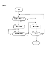
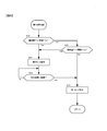
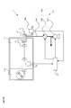
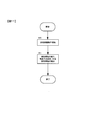
- the block diagram which shows the structure of the processing apparatus by the 1st Embodiment of this invention The flowchart explaining operation
- the processing apparatus provides a seal provided at an opening for carrying in and / or carrying out an object to be processed into the main chamber when processing with gas injection is performed in the main chamber of the gas atmosphere.
- a seal provided at an opening for carrying in and / or carrying out an object to be processed into the main chamber when processing with gas injection is performed in the main chamber of the gas atmosphere.
- FIG. 1 is a block diagram schematically showing the configuration of the processing apparatus 1.
- the processing device 1 includes an injection processing device 10, a main chamber 11, a feeding device 12, an inlet seal chamber 13, an outlet seal chamber 14, an exhaust device 15, a control device 17, and pressure sensors 18a and 18b. I have.
- the injection processing apparatus 10 is provided inside the main chamber 11 and forms a film on an object to be processed S such as a copper foil serving as a negative electrode current collector of a battery electrode or an aluminum foil serving as a positive electrode current collector of a battery electrode. I do.
- An example of the injection processing apparatus 10 is a PJD that mixes fine particles supplied from a powder supply device (not shown) with an inert gas such as nitrogen gas supplied from a gas supply source (not shown) and sprays the processed material S on the workpiece S This is a film forming apparatus using the (Powder Jet Deposition) method.
- the fine particles to be sprayed by the spray processing apparatus 10 include those made of various metals such as gold, silver, copper, aluminum, tin, nickel, titanium, and various alloys or intermetallic compounds such as Si—Cu and Si—Sn. Of these, ceramics such as aluminum oxide and zirconium oxide, those made of various inorganic glass materials, and those made of polymer compounds such as polyethylene can be used without particular limitation. In addition, fine particles obtained by combining different materials by a mechanical alloying method or the like, or fine particles obtained by coating the surfaces of different materials can be used.
- the spray processing apparatus 10 can use various film forming processing apparatuses such as a cold spray method and an aerosol deposition method instead of performing the film forming process by the PJD method.
- the spray processing apparatus 10 forms various films by the fine particles sprayed on the surface of the workpiece S to be processed, as well as those for spraying the fine particles on the workpiece S to form a film of the electrode active material. You may do it.
- the ejection processing apparatus 10 may be a removal processing apparatus that performs a removal process with fine particles ejected onto the surface of the workpiece S to be processed.
- the workpiece S can be appropriately selected according to the purpose of processing.
- the injection processing device 10 receives an injection command from the control device 17 and injects an inert gas mixed with fine particles at an injection amount T1 (m 3 / min).
- the control device 17 stores a plurality of injection amounts T1, and increases or decreases (including injection stop) the injection amount T1 at an appropriate timing according to a preset machining program. Further, the injection processing device 10 can increase or decrease the injection amount T1 at predetermined time intervals.
- the main chamber 11 is a container for the injection processing apparatus 10 to process the object to be processed under a certain atmospheric gas for the purpose of preventing oxidation, explosion prevention, moisture prevention, etc. of the object to be processed S and the fine particles to be injected.
- the main chamber 11 has an inlet 111 for carrying the workpiece S into the interior, and an outlet 112 for carrying the workpiece S processed by the jet processing apparatus 10 in the main chamber 11 to the outside. Is provided.
- the main chamber 11 is a sealed container that does not substantially have an opening communicating with the outside.
- the feeding device 12 is configured by a plurality of rollers or the like, and carries the workpiece S formed in a sheet shape into the main chamber 11 from the inlet 111, and the workpiece S processed in the main chamber 11. It is carried out from the outlet 112 to the outside of the main room 11.
- the jet processing apparatus 10 can process the workpiece S by a roll-to-roll method.
- the feeding speed of the workpiece S by the feeding device 12 can be set to 1 mm / sec to 100 mm / sec.
- the workpiece S can be conveyed continuously, and an intermittent operation that repeats conveyance / stopping may be performed as necessary.
- the inlet 111 and the outlet 112 are formed in an appropriate size so that the workpiece S can be conveyed while maintaining an appropriate clearance (interval) between the workpiece S and the workpiece.
- the inlet 111 and the outlet 112 do not require a special mechanism such as a labyrinth structure.
- the entrance seal chamber 13 is provided outside the entrance 111 of the main chamber 11 and communicates with both the inside and the outside of the main chamber 11.
- the outlet seal chamber 14 is provided outside the outlet 112 of the main chamber 11 and communicates with both the inside and the outside of the main chamber 11.
- the inlet seal chamber 13 and the outlet seal chamber 14 are provided to prevent outside air from flowing into the main chamber 11 while preventing the inert gas in the main chamber 11 from flowing out. Yes.
- the pressures P1a and P1b in the inlet seal chamber 13 and the outlet seal chamber 14 are controlled by the exhaust device 15 described later so that the differential pressure with respect to the external pressure P0 is within a predetermined range. Note that, within the predetermined range, as described later, it is possible to prevent the inert gas and fine particles in the main chamber 11 from being released to the outside via the inlet seal chamber 13 or the outlet seal chamber 14. Refers to the range of pressure.
- the control may be performed so that the differential pressure between either the pressure P1a or P1b and the external pressure P0 is within a predetermined range.
- a difference may be generated between the pressures P1a and P1b.
- the pressure P1a and P1b that have a smaller differential pressure with respect to the external pressure P0 may be selected as the control target.
- the seal chamber pressure P1 is set to the external pressure P0. It is preferable to maintain the pressure lower by about 8 Pa to 13 Pa as compared.
- the gas supplied from the outside is injected from the injection processing device 10 into the main chamber 11. At that time, the seal chamber pressures P1a and P1b are exhausted from the inlet seal chamber 13 and the outlet seal chamber 14 so that the pressure is always lower than the pressure in the main chamber 11.
- the exhaust device 15 includes a first exhaust system 150 including a first fan 151, a first variable valve 152, and a pipe line 154.
- the exhaust device 15 operates according to an instruction from the control device 17, which will be described later, and enters the inlet seal chamber 13.
- the gas is exhausted from the outlet seal chamber 14.
- the first fan 151 is configured by a turbo fan or the like, and is driven when a drive signal from a control device 17 described later is input, and the gas in the inlet seal chamber 13 and the outlet seal chamber 14 is moved to the outside of the main chamber 11. Discharge.
- the first fan 151 one that makes the rotational speed of the rotor blade variable, one that makes the rotor blade angle variable, or a combination of both can be used, and rotation of the rotor blade can be performed by a drive signal from the control device 17.
- the amount (exhaust capacity) that can be discharged to the outside of the inlet seal chamber 13 and the outlet seal chamber 14 is set depending on the number, the angle of the rotor blades, or a combination of both.
- the first variable valve 152 is composed of a motor-driven electric control valve.
- the first variable valve 152 adjusts the opening of the electric control valve in accordance with an opening signal input from the controller 17 described later, and exhausts gas discharged from the inlet seal chamber 13 and the outlet seal chamber 14 to the outside. Set the amount.
- the pipe 154 is provided with the first fan 151 and the first variable valve 152 described above. As shown in FIG. 1, the first variable valve 152 is provided on the intake side of the first fan 151. By adjusting the first fan 151 and the first variable valve 152 as described above, the inert gas in the inlet seal chamber 13 and the outlet seal chamber 14 is discharged to the outside through the pipe line 154. Note that the first variable valve 152 may be provided in the exhaust line 154 of the first fan 151 instead of being provided in the intake line 154 of the first fan 151 as shown in FIG. Good.
- the pressure sensors 18a and 18b are differential pressure gauges each having two pressure measurement ports and detecting and outputting a differential pressure between the two input pressures.
- One of the pressure measurement ports of the pressure sensors 18a and 18b is opened toward the outside of the main chamber 11, and the other is connected to each seal chamber.
- the pressure sensors 18a and 18b detect the differential pressure between the external pressure P0 and the pressure P1a in the inlet seal chamber 13 and the differential pressure between the external pressure P0 and the pressure P1b in the outlet seal chamber 14 to obtain the detected differential pressure.
- a corresponding signal (hereinafter referred to as a differential pressure signal) is output to the control device 17.
- the control device 17 includes a CPU, a ROM, a RAM, and the like, and is an arithmetic device that executes various data processing.
- the control device 17 operates the exhaust device 15 based on the input differential pressure signal and adjusts the exhaust amount of gas from the inlet seal chamber 13 and the outlet seal chamber 14 to thereby reduce the pressure between the seal chamber pressure and the external pressure. Control the differential pressure.
- the control device 17 outputs a drive signal that instructs the first fan 151 to drive.
- the control device 17 outputs an opening degree signal for designating the opening degree of the electric control valve constituting the first variable valve 152 to the first variable valve 152.
- the control device 17 selects the operation mode of the first exhaust system 150 as the first mode or the second mode in order to adjust the exhaust amount of the gas from the inlet seal chamber 13 and the outlet seal chamber 14.
- the control device 17 performs feedback control for operating the first exhaust system 150 based on the differential pressure between the pressure in the seal chamber and the external pressure.
- the control device 17 uses the first transfer function as an opening of the first variable valve 152, with the differential pressure ⁇ P1 between the seal chamber pressure P1 and the external pressure P0 being the first reference pressure as a controlled variable. That is, the operation amount of the electric control valve is calculated and output to the first variable valve 152 as an opening degree signal.
- the first transfer function is a function for calculating the operation amount of the first valve 152 in order to feedback control such as PI control or PID control on the differential pressure ⁇ P1.
- transfer functions such as P control, PI control, and PID control are appropriately mounted and used according to the response characteristics of the controlled system. it can. As a result, the amount of gas exhausted from the inlet seal chamber 13 and the outlet seal chamber 14 is adjusted.
- the control device 17 operates the first exhaust system 150 by performing feedforward control without performing feedback control, and exhausts from the inlet seal chamber 13 and the outlet seal chamber 14. Let In this case, the control device 17 outputs an injection command to the injection processing device 10 and at the same time sets the operation amount of the electric control valve of the first variable valve 152 to a predetermined value and sets the first variable as the opening signal. Output to valve 152. For example, the control device 17 outputs an opening degree signal so that the opening degree of the electric control valve of the first variable valve 152 is maintained at the maximum opening degree. Accordingly, the first exhaust system 150 operates with an exhaust amount corresponding to the opening of the first variable valve 152.
- the opening degree of the electric control valve of the first variable valve 152 is not limited to the one that is held at the maximum opening degree, and is held at a preset opening degree such as 90% or 80% of the maximum opening degree, for example. Moreover, what changes an opening degree according to progress of time is contained in 1 aspect of this invention.
- the operation amount of the electric control valve is such that the outflow of gas to the outside can be suppressed even if the gas exhaust amount is adjusted in the first mode after the elapse of time t1 described later. It is assumed that the exhaust gas that can be exhausted in the main chamber 11 by the process 10 is obtained in advance by an experiment or the like and recorded in a predetermined memory (not shown).
- the control device 17 adjusts the exhaust amount of the gas from the inlet seal chamber 13 and the outlet seal chamber 14 by appropriately switching between the first mode and the second mode, so that the seal chamber pressure P1 and the external pressure P0
- the differential pressure ⁇ P1 is controlled.
- the inlet seal chamber 13 and the outlet seal chamber 14 communicate with the main chamber 11 and have a pressure lower than the pressure of the main chamber 11. For this reason, by exhausting from the inlet seal chamber 13 and the outlet seal chamber 14, the inert gas injected into the main chamber 11 by the injection processing device 10 flows into the inlet seal chamber 13 and the outlet seal chamber 14, It is discharged to the outside by the exhaust device 15.
- An abatement device such as a scrubber or a filter can be installed at the exhaust end of the exhaust device 15 as necessary.
- the control device 17 sets the operation mode of the exhaust device 15 to one of the first mode and the second mode according to the size of the injection amount T1 of the inert gas injected by the injection processing device 10 during the processing. To do. That is, the control device 17 performs transition and return between the first mode and the second mode as necessary. In the present embodiment, the control device 17 sets the first mode when the injection amount T1 of the inert gas to be injected by the injection processing device 10 is equal to or less than a predetermined threshold value T1a, and sets the threshold value T1a. If it exceeds, the second mode is set.
- the control device 17 shifts the operation mode from the first mode to the second mode.
- the threshold value T1a is an exhaust amount that can suppress the outflow of gas to the outside even when the inert gas that has rapidly increased in the main chamber 11 by the processing of the injection processing device 10 is adjusted in the first mode. It is assumed that it is measured in advance by an experiment or the like and recorded in a predetermined memory (not shown).
- a signal indicating the injection amount T ⁇ b> 1 injected by the injection processing device 10 is transmitted to the control device 17 simultaneously with the injection or prior to the injection. It is also good.
- the control device 17 When the operation of the exhaust device 15 shifts to the second mode, the control device 17 starts a timer (not shown) and starts measuring time after the exhaust device 15 starts operating in the second mode. When the predetermined time t1 has elapsed since the start of time measurement, the control device 17 shifts the operation mode of the exhaust device 15 from the second mode to the first mode. That is, the control device 17 calculates the opening degree of the electric control valve of the first variable valve 152 using the differential pressure ⁇ P1 between the seal chamber pressure P1 and the external pressure P0 as a controlled variable, and uses the first variable valve 152 as an opening signal. Perform feedback control to output to.
- the differential gas ⁇ P1 is generated when the inert gas rapidly increased in the main chamber 11 by the processing of the injection processing device 10 is exhausted by operating the first exhaust system 150 in the second mode. Is measured in advance by an experiment or the like and recorded in a predetermined memory (not shown) as the time required until the control can be performed by the operation of the first exhaust system 150 in the first mode.
- the control device 17 changes the opening degree of the electric control valve of the first variable valve 152, but changes the exhaust capability of the first fan 151, the exhaust capability of the first fan 151, and the first variable. What changes the combination of the opening degree of the electric control valve of the valve 152 is also included in one embodiment of the present invention.
- control device 17 The processing by the control device 17 will be described using the flowchart of FIG. Each process shown in the flowchart of FIG. 2 is performed by executing a program in the control device 17. This program is stored in a memory (not shown), and is started and executed by the control device 17 when the processing device 1 starts operating.
- step S10 it is determined whether or not the injection amount T1 of the inert gas by the injection processing device 10 exceeds the threshold value T1a. If the injection amount T1 is less than or equal to the threshold value T1a, a negative determination is made in step S10 and the process proceeds to step S11.
- step S11 the exhaust device 15 is operated in the first mode, and the process proceeds to step S12.
- step S12 it is determined whether or not to end the operation of the processing device 1. When the operation of the processing device 1 is to be terminated, an affirmative determination is made in step S12 and the processing is terminated. If the processing device 1 continues to operate, a negative determination is made in step S12 and the process returns to step S10.
- step S10 If the injection amount T1 of the inert gas by the injection processing device 10 exceeds the threshold value T1a in step S10, an affirmative determination is made in step S10 and the process proceeds to step S13.
- step S13 the exhaust device 15 is operated in the second mode, and the process proceeds to step S14.
- step S13 a timer (not shown) is activated to start time measurement.
- step S14 it is determined whether or not a predetermined time t1 has elapsed since the time measurement was started by the timer in step S13. If the predetermined time t1 has elapsed, an affirmative determination is made in step S14 and the process proceeds to step S11. If the predetermined time t1 has not elapsed, a negative determination is made in step S14 and the process of step S14 is repeated.
- the feeding device 12 starts to carry the material into the main chamber 11 from the inlet 111 of the workpiece S formed in a sheet shape in a roll-to-roll manner.
- the control device 17 starts controlling the differential pressure ⁇ P1 between the seal chamber pressure P1 and the external pressure P0.
- the jet processing apparatus 10 jets a mixed fluid of fine particles and gas toward the workpiece S carried into the main chamber 11.
- the operation of the exhaust device 15 is preferably started prior to the start of the injection of the mixed fluid by the injection processing device 10.
- the processing object S to which the processing has been applied and the fine particles are adhered is sequentially carried out of the main chamber 11 from the outlet 112 by the feeding device 12.
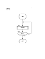
- step S80 the control device 7 operates the exhaust device 15 to start control of the differential pressure ⁇ P1 between the seal chamber pressure P1 and the external pressure P0, and proceeds to step S81.
- step S81 the feeding device 12 starts to carry the workpiece S into the main chamber 11, and the jet processing device 10 jets a fluid mixture of fine particles and gas toward the workpiece S to adhere.
- the processed object S is made to collide with and adhere to the surface, and the processed object S is carried out of the main chamber 11 by the feeding device 12, and the processing is completed.
- an active material film is formed on an electrode substrate by a PJD (Powder Jet Deposition) method, and a negative electrode material for a battery such as a lithium ion secondary battery is formed.
- a conductive base material such as copper (Cu) or a conductive resin is used for the electrode base material as the object to be processed S as a material constituting the current collector.
- an active material film can be formed on the surface of the material constituting the current collector in the same manner as the processing method by the injection processing apparatus 10 shown in FIG.
- a negative electrode is formed by punching out this electrode material into a shape and size that matches the battery type (for example, cylindrical type, square type, cell type, laminate type, etc.).
- a known positive electrode in which a lithium transition metal oxide such as lithium cobaltate is adhered to an aluminum foil as a positive electrode active material is opposed to the negative electrode with a separator interposed therebetween, and a known electrolyte (non-aqueous) is known in a known solvent.
- the lithium ion secondary battery is configured by enclosing it together with the electrolyte.
- known solvents are propylene carbonate, ethylene carbonate, etc.
- known electrolyte is LiClO 4 or LiPF 6 or the like.
- a lithium ion secondary battery that can be stably held for a long period of time with a high electric capacity is obtained.
- it may replace with what forms the negative electrode material of a lithium ion secondary battery using the injection processing apparatus 1, and may form positive electrode material.
- the electrode base material for example, a conductive base material such as aluminum or a conductive resin is used.
- the control device 17 shifts the operation mode of the exhaust device 15 between the first mode and the second mode, thereby adjusting the exhaust amount by the first exhaust system 150 to adjust the seal chamber pressure P1 and the external pressure.
- a differential pressure ⁇ P1 with P0 is controlled.
- the control device 17 uses the differential pressure ⁇ P1 between the seal chamber pressure P1 and the external pressure P0 that is the first reference pressure as a controlled variable, and uses the differential pressure according to the operation amount calculated by the first transfer function.
- ⁇ P1 is feedback-controlled.
- the control device 17 sets the exhaust amount to a predetermined set value regardless of the pressure difference ⁇ P1 between the seal chamber pressure P1 and the external pressure P0.
- the control device 17 changes the control mode of the first exhaust system 150 from the first mode to the second mode. Change to mode.
- the processing apparatus 1 uses the first exhaust system 150 to set the differential pressure ⁇ P1 between the seal chamber pressure P1 and the external pressure P0 to feedforward control and feedback control. Is controlled so that the seal chamber pressure P1 is lower than the external pressure P0. For this reason, when the pressure difference ⁇ P1 between the seal chamber pressure P1 and the external pressure P0 is within a predetermined range, the state where the seal chamber pressure P1 is lower than the external pressure P0 by a predetermined pressure is maintained using feedback control. it can. When the inert gas injected by the injection processing apparatus 10 increases rapidly and the differential pressure ⁇ P1 is expected to exceed the range of feedback control, exhaust from the seal chamber is performed using feedforward control.
- the differential pressure ⁇ P1 can be returned in a short period until it becomes a value that can be controlled by feedback control, and the seal chamber pressure P1 can be reduced by a predetermined magnitude relative to the external pressure P0.
- the injection processing device 10 even if a process involving a large amount of inert gas injection is performed in a short time by the injection processing device 10, the outflow of the inert gas from the main chamber 11 and the inflow of outside air into the main chamber 11 are suppressed. Can do. That is, it has a special labyrinth mechanism for preventing the outflow of the inert gas from the main chamber 11 to the outside of the main chamber 11 and the inflow of the oxidizing gas from the outside of the main chamber 11 to the main chamber 11.
- the airtightness of the main chamber 11 can be maintained. Further, since there is no need to provide a seal member that contacts the object to be processed S, there is no problem of scratching the object to be processed S, and product quality deterioration can be prevented. Furthermore, since it is not necessary to have a seal member that is in contact with or possibly in contact with the workpiece S, the feeding device 12 can be driven without resistance so that the workpiece S can be taken in and out of the main chamber 11.
- the control device 17 shifts the operation mode of the first exhaust system 150 from the second mode to the first mode when the predetermined time t1 has elapsed since the shift to the second mode. Therefore, the feedback control and the feedforward control are appropriately switched using a simple mechanism, the seal chamber pressure P1 is kept lower than the external pressure P0, and the outflow of the inert gas from the main chamber 11 to the outside. Inflow of outside air into the main chamber 11 can be suppressed.
- the first exhaust system 150 is provided on the intake side or the exhaust side of the first fan 151 and the first fan 151 in order to discharge the inert gas inside the inlet seal chamber 13 and the outlet seal chamber 14 to the outside.
- the first variable valve 152 is provided.
- the control device 17 adjusts the exhaust amount of the first exhaust system 150 by controlling at least one of the exhaust capability of the first fan 151 and the opening of the first variable valve 152. For this reason, the airtightness of the main chamber 11 can be maintained by holding the seal chamber pressure P1 lower than the external pressure P0 with a simple configuration using a fan.
- the same effect can be realized by using a vacuum pump such as a rotary pump or a swinging piston type pump instead of the first fan 151.
- the differential pressure ⁇ P1 between the seal chamber pressure P1 and the external pressure P0 is controlled to be within a predetermined range. As a result, even when the processing apparatus 1 is urgently stopped due to a power failure or the like, the outflow of inert gas from the main chamber 11 and the inflow of outside air into the main chamber 11 can be suppressed.
- the first embodiment is different in that the operation mode of the exhaust device is shifted from the second mode to the first mode based on a decrease in the seal chamber pressure due to the exhaust device operating in the second mode. Different from form.
- the processing apparatus 1 according to the second embodiment has the same configuration as that of the first embodiment shown in FIG. Even after starting the operation of the exhaust device 15 in the second mode, the control device 17 uses the differential pressure ⁇ P1 between the seal chamber pressure P1 input from the pressure sensor 18a or 18b and the external pressure P0 as a controlled variable.
- the opening degree of the first variable valve 152 that is, the operation amount of the electric control valve is calculated using one transfer function.
- the control device 17 compares the calculated operation amount with the predetermined threshold value T2a.
- the control device 17 Shifts from the second mode to the first mode to operate the exhaust device 15.
- the control device 17 performs the calculation of the manipulated variable and the comparison with the threshold value T2a every predetermined cycle (time interval) while the operation of the exhaust device 15 in the second mode is continued.
- the threshold value T2a is the maximum manipulated variable that can be exhausted in the first mode by the inert gas rapidly increasing in the main chamber 11 due to the processing of the injection processing apparatus 10 without generating hunting or the like. It is assumed that they are measured in advance by a method such as the above and recorded in a predetermined memory (not shown).
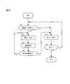
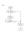
- control device 17 The processing by the control device 17 will be described using the flowchart of FIG. Each process shown in the flowchart of FIG. 3 is performed by executing a program in the control device 17. This program is stored in a memory (not shown), and is started and executed by the control device 17 when the processing device 1 starts operating.
- step S20 judgment between injection amount T1 and threshold T1a
- step S23 second mode setting
- step S10 judgment between injection amount T1 and threshold T1a
- step S13 in FIG. This is the same as the processing up to (second mode setting).
- step S24 the opening of the first variable valve 152, that is, the electric control is performed using the first transfer function, using the differential pressure ⁇ P1 between the seal chamber pressure P1 and the external pressure P0 input from the pressure sensor 18a or 18b as a controlled variable.
- the operation amount of the valve is calculated and the process proceeds to step S25.
- step S25 it is determined whether or not the calculated operation amount is equal to or less than a threshold value T2a. If the operation amount is equal to or less than the threshold value T2a, an affirmative determination is made in step S25 and the process proceeds to step S21. If the operation amount exceeds the threshold value T2a, a negative determination is made in step S25, and the process returns to step S23.
- the following functions and effects are obtained. It is done.
- the control device 17 calculates the value of the operation amount by the first transfer function during the continuation of the second mode, and sets the control mode of the first exhaust system 150 to the first when the calculated operation amount value falls below the threshold value T2a.
- the mode is returned from the second mode to the first mode. Therefore, compared with the case of returning to the first mode based on the result of time measurement, it is possible to return to the first mode directly based on the operation amount, so that the differential pressure ⁇ P1 is held at a desired pressure with higher accuracy. be able to.
- the control device 17 sets the operation mode of the first exhaust system 150 to the second mode when the differential pressure ⁇ P1 between the seal chamber pressure P1 input from the pressure sensor 18a or 18b and the external pressure P0 is equal to or less than a predetermined threshold value.
- a predetermined threshold value is also included in one embodiment of the present invention.
- the above-mentioned threshold is the maximum differential pressure that can be exhausted in the first mode without causing hunting or the like, which is caused by the inert gas that suddenly increases in the main chamber 11 by the processing of the injection processing device 10. Or the like and is recorded in a predetermined memory (not shown).
- the exhaust device of the processing apparatus includes a second exhaust system for exhausting the inert gas from the main chamber in addition to the first exhaust system for exhausting the inert gas from the inlet seal chamber and the outlet seal chamber. It differs from the first embodiment in that it includes an exhaust system.
- the differential pressure between the internal pressure in the main chamber and the external pressure in the main chamber is further controlled. Therefore, exhaust from the main room is also performed.
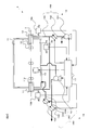
- the processing apparatus 1 further includes a main chamber pressure sensor 20, and the exhaust device 15 has a second exhaust system 160 in addition to the first exhaust system 150.
- the main chamber pressure sensor 20 has two pressure measurement ports, and is a differential pressure gauge that detects and outputs a differential pressure between two input pressures.
- One pressure measurement port is connected to the main chamber 11 and the other is a main pressure sensor. It is open to the outside of the chamber 11.
- the main chamber pressure sensor 20 detects a differential pressure between the external pressure P0 and the pressure P2 of the main chamber 11, and sends a signal corresponding to the detected differential pressure (hereinafter, a main chamber differential pressure signal) to the control device 17.
- a main chamber differential pressure signal a signal corresponding to the detected differential pressure
- the second exhaust system 160 of the exhaust device 15 further includes a second exhaust system 160 including a second fan 161, a second variable valve 162, a third variable valve 163, and a conduit 164, which will be described later. In this way, the inert gas is exhausted from the main chamber 11 by the drive signal from the control device 17.
- the second fan 161 is rotationally driven when a drive signal is input from the control device 17 as will be described later, and discharges the inert gas in the main chamber 11 to the outside.
- the second fan 161 can be one that makes the rotational speed of the rotor blade variable, one that makes the rotor blade angle variable, or a combination of both.
- the amount (exhaust capacity) that can be discharged to the outside of the main chamber 11 is set according to the number of rotations of the rotor blades, the angle of the rotor blades, or a combination thereof.
- the second variable valve 162 and the third variable valve 163 are configured by motor-driven electric control valves, and the second variable valve 162 and the third variable valve 163 are electrically controlled according to the opening signal input from the control device 17.
- the opening of the valve is adjusted. As a result, the amount of inert gas discharged from the main chamber 11 to the outside is set.
- the conduit 164 includes an exhaust conduit 164a for exhausting the inert gas exhausted from the main chamber 11 to the outside, and a reflux conduit 164b for returning the inert gas once exhausted from the main chamber 11 to the main chamber 11 again. It is composed of As shown in FIG. 4, the above-described second variable valve 162 is provided in the exhaust pipe line 164a, and the third variable valve 163 is provided in the reflux pipe line 164b. Note that the pipe 164 that does not include the reflux pipe 164b and the third variable valve 163 is also included in one embodiment of the present invention. In this case, the second exhaust system 160 only discharges the inert gas from the main chamber 11 to the outside in response to a command from the control device 17.
- the control device 17 operates the first exhaust system 150 of the exhaust device 15 in the same manner as in the first embodiment, and adjusts the exhaust amount from the inlet seal chamber 13 and the outlet seal chamber 14 to thereby adjust the differential pressure ⁇ P1. To control. Furthermore, the control device 17 controls the differential pressure between the main chamber pressure P ⁇ b> 2 of the main chamber 11 and the external pressure P ⁇ b> 0 to be within a predetermined range by the second exhaust system 160. In the present embodiment, as an example, it is assumed that the differential pressure is controlled so that the main chamber pressure P2 is lower than the external pressure P0 by about 5 Pa to 10 Pa.
- the pressure in the main chamber 11 is not limited to the one controlled to the above value, and is set according to the size of the main chamber 11, the injection amount T1 of the inert gas by the injection processing device 10, and the like. It is preferable.
- the control device 17 operates the second exhaust system 160 to adjust the exhaust amount of the inert gas from the main chamber 11.
- the control device 17 outputs a drive signal that instructs the second fan 161 to drive.
- the control device 17 outputs an opening degree signal for specifying the opening degree of the electric control valve constituting the second variable valve 162 and the third variable valve 163 to the second variable valve 162 and the third variable valve 163, respectively.
- the control device 17 controls the differential pressure between the main chamber pressure P2 and the external pressure P0 by shifting the operation mode of the second exhaust system 160 between the third mode and the fourth mode.
- the control device 17 performs feedback control that operates the second exhaust system 160 based on the differential pressure between the main chamber pressure P2 of the main chamber 11 and the external pressure P0.
- the control device 17 uses the differential pressure ⁇ P2 between the main chamber pressure P2 and the external pressure P0 as the second reference pressure based on the main chamber differential pressure signal input from the main chamber pressure sensor 20 as a controlled variable.
- the opening of the second variable valve 162 and the third variable valve 163, that is, the operation amount of the electric control valve is calculated using the second transfer function, and the opening signal is sent to the second variable valve 162 and the third variable valve 163. Output.
- the second transfer function is a function for calculating the operation amounts of the second variable valve 162 and the third variable valve 163 in order to feedback control the differential pressure ⁇ P2 such as PI control and PID control.
- transfer functions such as P control, PI control, and PID control are appropriately mounted and used according to the response characteristics of the controlled system. it can.
- the control device 17 controls the opening of the second variable valve 162 and the third variable valve 163 in a complementary manner, and keeps the total amount of inert gas exhausted from the main chamber 11 through the second fan 161, By changing the ratio of recirculation to the main chamber 11 and the ratio of the inert gas discharged to the outside, the net exhaust amount from the main chamber 11 is increased or decreased. For example, when 20 percent of the total amount of the inert gas exhausted from the main chamber 11 is returned to the main chamber 11, the second variable valve 162 and the third variable valve 163 are discharged so that 80 percent is discharged to the outside. Adjust the opening.
- the control device 17 operates the second exhaust system 160 by performing feedforward control without performing feedback control, and exhausts from the main chamber 11.
- the control device 17 outputs the injection command to the injection processing device 10 and simultaneously sets the operation amount of the electric control valve of the second variable valve 162 to a predetermined value, and sets the second variable valve as an opening signal. Output to 162.
- the control device 17 outputs an opening degree signal so that the opening degree of the electric control valve of the second variable valve 162 becomes the maximum opening degree.
- the second exhaust system 160 operates with an exhaust amount corresponding to the opening of the second variable valve 162.
- the opening degree of the electric control valve of the second variable valve 162 is not limited to that maintained at the maximum opening degree, and is held at a preset opening degree, for example, 90% or 80% of the maximum opening degree. A thing which changes an opening degree according to passage of time and time is included in one mode of the present invention.
- the operation amount of the electric control valve is such that the outflow of gas to the outside can be suppressed even if the gas exhaust amount is adjusted in the third mode after the elapse of time t2, which will be described later. It is assumed that the exhaust gas that can be exhausted in the main chamber 11 by the process 10 is obtained in advance by an experiment or the like and recorded in a predetermined memory (not shown).
- the second exhaust system 160 is not limited to be operated simultaneously with the output of the injection command to the injection processing device 10, and is operated after a predetermined time from the output of the injection command, or the injection amount from the injection processing device 10. Those that are operated based on the above are also included in one embodiment of the present invention.
- the control device 17 shifts the operation mode of the first exhaust system 150 between the first mode and the second mode based on a predetermined condition, so that the inlet seal
- the amount of exhaust from the chamber 13 and the outlet seal chamber 14 is adjusted to control the differential pressure ⁇ P1 between the seal chamber pressure P1 and the external pressure P0.
- the control device 17 adjusts the exhaust amount from the main chamber 11 by shifting the operation mode of the second exhaust system 160 based on a predetermined condition between the third mode and the fourth mode, A differential pressure ⁇ P2 between the main chamber pressure P2 and the external pressure P0 is controlled.
- setting of the first mode to the fourth mode by the control device 17 will be described.
- the control device 17 sets the second mode and the fourth mode when the injection amount T1 of the inert gas to be injected by the injection processing device 10 during the processing exceeds a predetermined threshold value T1b set in advance. To do. When the injection amount T1 exceeds the threshold value T1b, the control device 17 operates the first exhaust system 150 in the second mode and operates the second exhaust system 160 in the fourth mode.
- the control device 17 When the injection amount T1 is equal to or less than the threshold value T1b, the control device 17 operates the second exhaust system 160 in the third mode. That is, the controller 17 uses the second variable valve 162 and the third variable valve 163 to calculate the opening signals calculated using the differential pressure ⁇ P2 between the main chamber pressure P2 input from the main chamber pressure sensor 20 and the external pressure P0 as a controlled variable. Perform feedback control to output to.
- the threshold value T1b is set to be larger than the threshold value T1a, and when the inert gas is injected into the main chamber 11 by the processing of the injection processing device 10, the second exhaust system 160 is set to the third mode. Assuming that the differential pressure ⁇ P2 is controllable even if it is operated in the above, it is preliminarily measured by an experiment or the like and recorded in advance in a memory (not shown).
- the control device 17 instructs the second exhaust system 160 to operate in the fourth mode
- the control device 17 starts a timer (not shown) and measures the time after the second exhaust system 160 starts the operation in the fourth mode. Start.
- the control device 17 shifts the operation mode of the second exhaust system 160 from the fourth mode to the third mode.
- the predetermined time t2 is such that the inert gas that has rapidly increased in the main chamber 11 due to the processing of the injection processing apparatus 10 is exhausted by operating the second exhaust system 160 in the fourth mode to exhaust the pressure difference ⁇ P2. Is measured in advance by an experiment or the like and recorded in a predetermined memory (not shown) as the time required until the control can be performed by the operation of the second exhaust system 160 in the third mode.
- the control device 17 when the injection amount T1 is equal to or less than the threshold value T1b, that is, when the second exhaust system 160 is operating in the third mode, the control device 17 further compares the magnitudes of the injection amount T1 and the threshold value T1a. To do. In accordance with the comparison result, the control device 17 controls the differential pressure ⁇ P1 between the seal chamber pressure P1 and the external pressure P0 by the first exhaust system 150, as in the case of the first embodiment. That is, the control device 17 operates the first exhaust system 150 in the first mode when the injection amount T1 is equal to or less than the threshold T1a, and operates in the second mode when the injection amount T1 exceeds the threshold T1a. The first exhaust system 150 is operated.
- the control device 17 changes the opening degree of the electric control valve of the second variable valve 162 in the third mode and the fourth mode. However, the control device 17 changes the exhaust capacity of the second fan 161. What changes the combination of the exhaust capacity of the fan 161 and the opening degree of the electric control valve of the second variable valve 162 is also included in one aspect of the present invention.
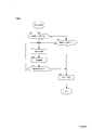
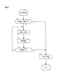
- control device 17 The processing by the control device 17 will be described using the flowcharts of FIGS. Each process shown in the flowcharts of FIGS. 5 to 7 is performed by executing a program in the control device 17. This program is stored in a memory (not shown), and is started and executed by the control device 17 when the processing device 1 starts operating.
- step S31 of FIG. 5 exhaust processing is performed and the process proceeds to step S32. Details of the exhaust processing will be described later with reference to FIGS.
- step S32 it is determined whether or not to end the operation of the processing device 1. When the operation of the processing device 1 is to be ended, an affirmative determination is made in step S32 and the processing is ended. If the processing device 1 continues to operate, a negative determination is made in step S32 and the process returns to step S30.
- step S40 it is determined whether or not the injection amount T1 of the inert gas to be injected by the injection processing device 10 exceeds the threshold value T1b. If the injection amount T1 exceeds the threshold value T1b, an affirmative determination is made in step S40 and the process proceeds to step S41. If the injection amount T1 is less than or equal to the threshold value T1b, a negative determination is made in step S40, and the process proceeds to step S43 described later.
- step S41 the first exhaust system 150 is operated in the second mode, and the process proceeds to step S42.
- step S41 a timer (not shown) is activated to start time measurement.
- step S42 it is determined whether or not a predetermined time t1 has elapsed since the time measurement was started by the timer in step S41. If the predetermined time t1 has elapsed, an affirmative determination is made in step S42 and the process proceeds to step S44 described later. If the predetermined time t1 has not elapsed, a negative determination is made in step S42, and the process of step S42 is repeated.
- step S40 determines whether or not the injection amount exceeds a threshold value T1a. If the injection amount exceeds the threshold value T1a, an affirmative determination is made in step S43 and the process proceeds to step S41. If the injection amount T1 is less than or equal to the threshold value T1a, a negative determination is made in step S43 and the process proceeds to step S44. In step S44, the first exhaust system 150 is operated in the first mode, and the process shown in FIG. 6 ends.
- step S50 it is determined whether or not the injection amount T1 of the inert gas by the injection processing device 10 exceeds the threshold value T1b. If the injection amount T1 exceeds the threshold value T1b, an affirmative determination is made in step S50 and the process proceeds to step S51. If the injection amount T1 is less than or equal to the threshold value T1b, a negative determination is made in step S50, and the process proceeds to step S53 described later.
- step S51 the second exhaust system 160 is operated in the fourth mode, and the process proceeds to step S52.
- a timer (not shown) is activated to start time measurement.
- step S52 it is determined whether or not a predetermined time t2 has elapsed since the time measurement was started by the timer in step S51. If the predetermined time t2 has elapsed, an affirmative determination is made in step S52 and the process proceeds to step S53. If the predetermined time t2 has not elapsed, a negative determination is made in step S52, and the process of step S52 is repeated.
- step S50 If the injection amount T1 is less than or equal to the threshold value T1b, a negative determination is made in step S50 and the process proceeds to step S53.
- step S53 the second exhaust system 160 is operated in the third mode, and the process shown in FIG. 7 ends.
- the main chamber 11 constituting the processing apparatus 1 has dimensions of 1340 mm ⁇ 1300 mm ⁇ 590 mm and has a volume of about 1.2 m 3 .
- the processing apparatus 1 includes four injection processing apparatuses 10, of which two of the injection processing apparatuses 10 perform film formation on the surface of the workpiece S, and the remaining two jet processing apparatuses 10 are the processing objects. A film forming process is performed on the back surface of S.
- the total injection quantity T1 of four is, 0m 3 /min,0.3m 3 /min,0.6m 3 /min,0.9m 3 / Min and 1.2 m 3 / min, which is one of four stages, and is configured such that the injection amount T1 can be increased or decreased at intervals of a maximum of 1 second.
- the first fan 151 operates at an air volume of 8.1 m 3 / min, a static pressure of 2.1 kPa, and a power of 0.4 kW / 200V.
- the second fan 161 operates at an air volume of 12 m 3 / min, a static pressure of 2 kPa, and a power of 0.4 kW / 200V.
- the electromagnetic control valve of the first variable valve 152, the electromagnetic control valve of the second variable valve 162, and the electromagnetic control valve of the third variable valve 163 perform a fully open to fully closed operation in 1.5 seconds or less.
- the pipe line 154 is a pipe having a diameter of 40 mm
- the pipe line 164 is a pipe having a diameter of 80 mm.
- the control device 17 uses the differential pressure ⁇ P2 between the main chamber pressure P2 and the external pressure P0 as a controlled variable, and feedback-controls the differential pressure ⁇ P2 according to the operation amount calculated by the second transfer function. To do.
- the control device 17 sets the exhaust amount to a predetermined set value regardless of the differential pressure ⁇ P2 between the pressure P2 inside the main chamber 11 and the external pressure P0.
- the control device 17 changes the operation mode of the second exhaust system 160 from the third mode to the fourth mode. It was made to move to.
- exhausting from the main chamber 11 in addition to exhausting from the inlet seal chamber 13 and the outlet seal chamber 14 prevents the main chamber 11 from entering the inlet seal chamber 13 and the outlet seal chamber 14. Since the amount of the active gas flowing in can be suppressed, the seal chamber pressure P1 can be lowered by a predetermined pressure with respect to the external pressure P0 in a short period.
- the main chamber pressure P2 greatly fluctuates due to the injection of the injection processing device 10
- the outflow of the inert gas to the outside of the main chamber 11 and the inflow of outside air into the main chamber 11 are suppressed, and the main chamber pressure P2 is suppressed.
- the airtightness of the chamber 11 can be improved.
- the control device 17 shifts the operation mode of the second exhaust system 160 from the fourth mode to the third mode when the predetermined time t2 has elapsed since the shift to the fourth mode. Therefore, the feedback control and the feedforward control are appropriately switched using a simple mechanism, the seal chamber pressure P1 is kept lower than the external pressure P0, and the outflow of the inert gas from the main chamber 11 to the outside. Inflow of outside air into the main chamber 11 can be suppressed.
- the second exhaust system 160 includes a reflux line 164b for refluxing the inert gas from the exhaust side of the second fan 161 into the main chamber 11, and a third variable valve 163 provided in the reflux line 164b. have.
- the control device 17 controls the displacement of the second exhaust system 160 by controlling at least one of the displacement of the second fan 161, the opening of the second variable valve 162, and the opening of the third variable valve 163. I adjusted it. For this reason, with a simple configuration using a fan, it is possible to prevent outflow of inert gas to the outside of the main chamber 11 and inflow of outside air into the main chamber 11 and maintain the airtightness of the main chamber 11. .
- the same effect can be realized by using a vacuum pump such as a rotary pump or a swinging piston type pump instead of the first fan 151.
- a processing apparatus according to the fourth embodiment of the present invention will be described.
- the same components as those in the third embodiment are denoted by the same reference numerals, and differences from the third embodiment will be mainly described. Points that are not particularly described are the same as those in the third embodiment.
- the processing apparatus is different from the third embodiment in the following points (1) and (2).
- (1) The operation mode of the first exhaust device is shifted from the second mode to the first mode based on the differential pressure between the seal chamber pressure P1 and the external pressure P0.
- the operation mode of the second exhaust system is shifted from the fourth mode to the third mode based on the differential pressure between the main chamber pressure P2 and the external pressure P0.
- the operation mode of the first exhaust system is shifted from the second mode to the first mode based on the differential pressure between the seal chamber pressure P1 and the external pressure P0.
- the control device 17 is the same as in the second embodiment. Perform the process. That is, the control device 17 compares the operation amount calculated using the first transfer function with the threshold value T2a for a predetermined period while the control of the exhaust device 15 in the first mode is continued. Perform every (time interval). As a result of the comparison, when the calculated operation amount is equal to or less than the threshold value T2a, the pressure difference ⁇ P1 between the seal chamber pressure P1 and the external pressure P0 is decreased to a pressure controllable by the first mode due to the decrease in the seal chamber pressure P1. And the control device 17 shifts the second mode to the first mode and operates the first exhaust system 150.
- the operation mode of the second exhaust system 160 is shifted from the fourth mode to the third mode based on the differential pressure between the main chamber pressure P2 and the external pressure P0.
- the control device 17 performs the second exhaust system in the fourth mode. Even after starting the control of 160, the differential pressure ⁇ P2 between the main chamber pressure P2 and the external pressure P0 based on the main chamber pressure signal input from the main chamber pressure sensor 20 is used as a controlled variable, and the second transfer function is used. 3
- the opening of the variable valve 163, that is, the operation amount of the electric control valve is calculated.
- the control device 17 compares the calculated operation amount with the predetermined threshold value T2b.
- the control device 17 makes the transition from the fourth mode to the third mode and operates the second exhaust system 160.
- the control device 17 performs the above calculation of the manipulated variable and the comparison with the threshold value T2b for each predetermined period (time interval) while the operation of the second exhaust system 160 in the fourth mode is continued.
- the threshold value T2b is an operation amount that can be discharged in the third mode by the inert gas rapidly increased in the main chamber 11 due to the processing of the injection processing device 10 without generating hunting or the like. It is assumed that it has been measured in advance and recorded in a predetermined memory (not shown).
- control device 17 The processing by the control device 17 will be described with reference to the flowcharts of FIGS. Each process shown in the flowcharts of FIGS. 5, 8, and 9 is performed by executing a program in the control device 17. This program is stored in a memory (not shown), and is started and executed by the control device 17 when the processing device 1 starts operating.
- FIG. 8 shows the processing for operating the first exhaust system 150 in step S31 of FIG.
- step S60 determination of injection amount T1 and threshold value T1b
- step S61 second mode setting
- step S40 determination of size of injection amount T1 and threshold value T1b
- step S41 first step
- step S62 the differential pressure ⁇ P1 between the seal chamber pressure P1 and the external pressure P0 based on the seal chamber pressure signal input from the pressure sensor 18a or b is used as a controlled variable, and the first variable valve 152 is controlled using the first transfer function.
- the opening degree that is, the operation amount of the electric control valve is calculated, and the process proceeds to step S63.
- step S63 it is determined whether or not the operation amount calculated in step S62 is equal to or less than a threshold value T2a. If the manipulated variable is less than or equal to the threshold value T2a, an affirmative determination is made in step S63 and the process proceeds to step S65.
- step S63 If the operation amount exceeds the threshold value T2a, a negative determination is made in step S63 and the process returns to step S61.
- step S64 determination of injection amount T1 and threshold value T1a
- step S65 first mode setting
- step S43 of FIG. 6 determination of size of injection amount T1 and threshold value T1a
- step S44 first step. 1 mode setting).
- FIG. 9 shows a process for operating the second exhaust system 160 in step S31 of FIG. Steps S70 (determination of injection amount T1 and threshold value T1a) and step S71 (fourth mode setting) are performed in steps S50 (determination of injection amount T1 and threshold value T1a) and step S51 (first step). This is the same as each process of (2 mode setting).
- step S72 the differential pressure ⁇ P2 between the main chamber pressure P2 and the external pressure P0 based on the main chamber pressure signal input from the main chamber pressure sensor 20 is used as a controlled variable, and the third variable valve 163 is controlled using the second transfer function.
- the opening degree that is, the operation amount of the electric control valve is calculated, and the process proceeds to step S73.
- step S73 it is determined whether or not the operation amount calculated in step S72 is equal to or less than a threshold value T2b. If the manipulated variable is less than or equal to the threshold value T2b, an affirmative determination is made in step S73 and the process proceeds to step S74.
- step S73 If the operation amount exceeds the threshold value T2b, a negative determination is made in step S73 and the process returns to step S71.
- step S74 the second exhaust system 160 is controlled in the third mode as in step S53 of FIG. 7, and the process shown in FIG. 9 is terminated.
- the effects (1) to (3) obtained by the first embodiment and the effect (1) obtained by the third embodiment are obtained.
- the following effects can be obtained.
- the control device 17 compares the operation amount value calculated by the second transfer function with the threshold value T2a during the continuation of the fourth mode, and when the control device 17 falls below the threshold value T2a, sets the control mode of the second exhaust system 160 to the first mode. It was made to return from 4 mode to 3rd mode. Therefore, compared to the case of returning to the third mode based on the result of time measurement, it is possible to return to the third mode directly based on the operation amount, so that the airtightness of the main chamber 11 can be maintained with higher accuracy. Can do.
- the control device 17 determines that the first exhaust system 150 when the differential pressure ⁇ P1 between the seal chamber pressure P1 input from the pressure sensor 18a or 18b and the external pressure P0 is equal to or less than a predetermined threshold value.
- the mode in which the operation mode is shifted from the second mode to the first mode is also included in one embodiment of the present invention.
- the above-mentioned threshold is the maximum differential pressure that can be exhausted in the first mode without causing hunting or the like, which is caused by the inert gas that suddenly increases in the main chamber 11 by the processing of the injection processing device 10. It is assumed that they are measured in advance by a method such as the above and recorded in a predetermined memory (not shown).
- control device 17 changes the operation mode of the second exhaust system 160 when the differential pressure ⁇ P2 between the main chamber pressure P2 input from the main chamber pressure sensor 20 and the external pressure P0 is equal to or less than a predetermined threshold value.
- a predetermined threshold value is the maximum differential pressure at which the inert gas rapidly increased in the main chamber 11 by the processing of the injection processing device 10 can be exhausted in the third mode without generating hunting or the like. It is assumed that they are measured in advance by a method such as the above and recorded in a predetermined memory (not shown).
- the external pressure P0 is commonly used as the first reference pressure and the second reference pressure.
- the exhaust amount of the first exhaust system is adjusted based on the differential pressure ⁇ P1 between the seal chamber pressure P1 and the external pressure P0, and the exhaust amount of the second exhaust system is adjusted to the differential pressure ⁇ P2 between the main chamber pressure P2 and the external pressure P0.
- the differential pressure between the main chamber pressure P2 and the seal chamber pressure P1 is controlled to a desired value, and the backflow of gas from the seal chamber to the main chamber 11 is suppressed.
- a mode in which the main chamber pressure P2 is the first reference pressure and a mode in which the seal chamber pressure P1 is the second reference pressure can be cited.
- the differential pressure ⁇ P1 between the seal chamber pressure P1 and the external pressure P0 is controlled with the external pressure P0 as the first reference pressure, and the main chamber pressure P2 and the seal chamber pressure P1 with the seal chamber pressure P1 as the second reference pressure.
- the second exhaust system 160 can be exhausted with high responsiveness.
- the main chamber pressure P2 is set as the first reference pressure, the differential pressure between the seal chamber pressure P1 and the main chamber pressure P2 is controlled, and the external pressure P0 is set as the second reference pressure, and the main chamber pressure P2 and the external pressure P0
- the differential pressure ⁇ P2 is controlled.
- the main chamber 11 is used to directly measure and control the differential pressure between the seal chamber pressure P1 and the main chamber pressure P2.
- the first exhaust system 150 can be exhausted with higher responsiveness to a change in the internal pressure, and can suppress the outflow of the inert gas from the seal chamber and / or the inflow of gas from the seal chamber into the main chamber.
- the differential pressure to be controlled is compared with the case where the external pressure P0 is the first reference pressure and the differential pressure ⁇ P1 is the control target. Since the value is small, the first exhaust system 150 can be driven with smaller power.
- the present invention includes a modification of the processing apparatus 1 described in the first to fourth embodiments as follows.
- the main chamber 11 includes any one of the inlet 111 and the outlet 112, and one of the corresponding inlet seal chamber 13 and the outlet seal chamber 14 is also included in one aspect of the present invention.
- FIG. 10 shows a case where an inlet 111 and an inlet seal chamber 13 are provided as an example.
- the control device 17 controls the differential pressure ⁇ P1 between the seal chamber pressure P1 and the external pressure P0 by causing the first exhaust system 150 to exhaust from the inlet seal chamber 13.
- the processed portion of the workpiece S carried into the main chamber 11 by the roll-to-roll method is wound and retained inside the main chamber 11.
- the processing may be taken out from the main chamber 11.
- a separate chamber 11a such as a shield chamber is provided in the main chamber 11 so that the fine particles ejected by the ejection processing apparatus 10 do not further adhere to the treated portion, and the treated portion is in the separate chamber 11a. It is desirable to be brought in.
- differential pressure sensors such as the pressure sensors 18a and 18b and the main chamber pressure sensor 20
- pressure sensors that respectively measure the absolute pressures of the inlet seal chamber 13, the outlet seal chamber 14, and the main chamber 11 are provided. Is also included in one embodiment of the present invention.
- an external pressure sensor that measures the absolute pressure outside the main chamber 11 is further provided, and the control device 17 determines whether the absolute pressure in the inlet seal chamber 13, the outlet seal chamber 14, and the main chamber 11 is the absolute pressure in the main chamber 11. By calculating the difference, the seal chamber pressure P1 and the main chamber pressure P2 are obtained.
- the difference between the input from the pressure sensor indicating a high pressure value and the external absolute pressure may be set as the seal chamber pressure P1.
- Each of the threshold values T1a and T1b may be set by an injection amount (m 3 ) within a predetermined time instead of the injection amount (m 3 / min).
- a plurality of injection processing devices may be provided in the main chamber 11, and each of the injection processing devices may operate with different injection amounts and injection timings. In this case, the threshold values T1a and T1b may be set based on the total amount of injection of each injection processing device.
- the present invention is not limited to the above-described embodiments, and other forms conceivable within the scope of the technical idea of the present invention are also included in the scope of the present invention. .
Landscapes
- Chemical & Material Sciences (AREA)
- Engineering & Computer Science (AREA)
- Chemical Kinetics & Catalysis (AREA)
- Manufacturing & Machinery (AREA)
- General Chemical & Material Sciences (AREA)
- Electrochemistry (AREA)
- Materials Engineering (AREA)
- Mechanical Engineering (AREA)
- Organic Chemistry (AREA)
- Metallurgy (AREA)
- Physical Vapour Deposition (AREA)
- Details Or Accessories Of Spraying Plant Or Apparatus (AREA)
- Physical Or Chemical Processes And Apparatus (AREA)
- Other Surface Treatments For Metallic Materials (AREA)
- Battery Electrode And Active Subsutance (AREA)
- Chemical Vapour Deposition (AREA)
- Plasma Technology (AREA)
Abstract
Description
本発明の第2の態様によると、第1の態様の処置装置において、制御部は、処理部により主室の内部に噴射されるガスの量が第1閾値を超える場合、動作モードを第1モードから第2モードに移行させることができる。
本発明の第3の態様によると、第1または第2の態様の処理装置において、制御部は、第2モードの場合には、予め設定された所定の排気量で、第1排気系統にシール室の内部から排気させることができる。
本発明の第4の態様によると、第1乃至3の何れか一態様の処理装置において、制御部は、第2モード時におけるシール室の内部の圧力低下に応じて、動作モードを第2モードから第1モードに移行させることができる。
本発明の第5の態様によると、第1乃至3の何れか一態様の処理装置において、制御部は、第2モードに移行してから所定時間が経過した場合、動作モードを第2モードから第1モードに移行させることができる。
本発明の第6の態様によると、第4の態様の処理装置において、制御部は、第2モードの継続中において、第1の差圧が第2閾値を下回る場合に、動作モードを第2モードから第1モードに移行させることができる。
本発明の第7の態様によると、第1乃至6の何れか一態様の処理装置において、第1排気系統は、シール室の内部を排気するために第1排気装置と、第1排気装置の吸気側または排気側に設けられた第1可変バルブとを備え、制御部は、第1排気装置の排気能力と第1可変バルブの開度とのうち少なくとも一方を変化させることにより第1の差圧を制御することができる。
本発明の第8の態様によると、第1乃至7の何れか一態様の処理装置において、排気部は、主室の内部を排気する第2排気系統を有し、制御部は、さらに、主室の内部の圧力と第2の基準圧力との第2の差圧を制御するための排気部の動作モードとして、第2の差圧に基づくフィードバック制御をして第2排気系統を動作させる第3モードと、第2の差圧に基づくフィードバック制御とは異なる制御をして第2排気系統を動作させる第4モードとを有し、制御部は、処理部によって主室の内部へ噴射されるガスの量の増加に応じて、動作モードを第3モードから第4モードへ移行させることができる。
本発明の第9の態様によると、第8の態様の処理装置において、制御部は、処理部により主室の内部に噴射されるガスの量が第3閾値を超える場合、動作モードを第3モードから第4モードに移行させることができる。
本発明の第10の態様によると、第8または9の態様の処理装置において、第4モードは、予め設定された所定の排気量で、第2排気系統に主室の内部から排気させることができる。
本発明の第11の態様によると、第8乃至10の何れか一態様の処理装置において、制御部は、第4モード時における主室の圧力低下に応じて、動作モードを第4モードから第3モードに移行させることができる。
本発明の第12の態様によると、第8乃至10の何れか一態様の処理装置において、制御部は、第4モードに移行してから所定時間が経過した場合、動作モードを第4モードから第3モードに移行させることができる。
本発明の第13の態様によると、第11の態様の処理装置において、制御部は、第4モードの継続中において、第2の差圧が第4閾値を下回る場合に、第2排気系統の動作モードを第4モードから第3モードに移行させることができる。
本発明の第14の態様によると、第8乃至13の何れか一態様の処理装置において、第2排気系統は、主室の内部を排出するための第2排気装置と、第2排気装置の吸気側または排気側に設けられた第2可変バルブとを備え、制御部は、第2排気装置の排気能力と第2可変バルブの開度とのうち少なくとも一方を変化させることにより、第2の差圧を制御することができる。
本発明の第15の態様によると、第8乃至14の何れか一態様の処理装置において、第2排気系統は、第2排気装置の排気側から主室の内部にガスを還流させる還流経路と、還流経路に設けられた第3可変バルブとを有し、制御部は、第2排気装置の排気能力、第2可変バルブの開度および第3可変バルブの開度のうち、少なくとも一つを変化させることにより、第2の差圧を制御することができる。
本発明の第16の態様によると、第15の態様の処理装置において、制御部は、第2可変バルブの開度と、第3可変バルブの開度とを相補的に変化させることができる。
本発明の第17の態様によると、第1乃至16の何れか一態様の処理装置において、第1の基準圧力は、主室の内部の圧力またはシール室の外部の圧力とすることができる。
本発明の第18の態様によると、第8乃至17の何れか一態様の処理装置において、第2の基準圧力は、主室の外部の圧力またはシール室の内部の圧力とすることができる。
本発明の第19の態様によると、第8乃至14の何れか一態様の処理装置において、第1閾値は第3閾値よりも小さくすることができる。
本発明の第20の態様によると、噴射処理方法は、第1乃至19の何れか一態様の処理装置を用い、主室内で被処理物に噴射処理を行う。
本発明の第21の態様によると、第20の態様の噴射処理方法において、噴射処理は、被処理物に固気二相流を噴射することができる。
本発明の第22の態様によると、電極材料の製造方法は、第1乃至19の何れか一態様の処理装置を用い、集電体表面に活物質皮膜を形成する。
図面を参照しながら、本発明の第1の実施の形態による処理装置1について説明する。図1は、処理装置1の構成を模式的に示すブロック図である。処理装置1は、噴射処理装置10と、主室11と、送り装置12と、入口シール室13と、出口シール室14と、排気装置15と、制御装置17と、圧力センサ18aおよび18bとを備えている。
第1モードでは、制御装置17は、シール室の圧力と外部圧力との差圧に基づいて、第1排気系統150を動作させるフィードバック制御を行う。この場合、制御装置17は、シール室圧力P1と第1の基準圧力である外部圧力P0との差圧ΔP1を被制御変数として、第1伝達関数を用いて第1可変バルブ152の開度、すなわち電気制御弁の操作量を算出し、開度信号として第1可変バルブ152へ出力する。なお、第1伝達関数は、差圧ΔP1をPI制御やPID制御等のフィードバック制御するために第1バルブ152の操作量を算出するための関数である。本実施の形態における第1伝達関数の関数形に関して特別な制限はなく、被制御系の応答特性等に応じて、P制御やPI制御、PID制御等の伝達関数を適宜実装して用いることができる。その結果、入口シール室13および出口シール室14からの気体の排気量が調整される。
第2モードでは、制御装置17は、フィードバック制御は行わずフィードフォーワード制御を行うことにより第1排気系統150を動作させて、入口シール室13および出口シール室14から排気させる。この場合、制御装置17は、噴射処理装置10に噴射指令を出力すると同時に、第1可変バルブ152の電気制御弁の操作量を予め定められた値に設定して、開度信号として第1可変バルブ152へ出力する。たとえば、制御装置17は、第1可変バルブ152の電気制御弁の開度が最大開度に保持されるように開度信号を出力する。これにより、第1排気系統150は、第1可変バルブ152の開度に応じた排気量で動作する。なお、第1可変バルブ152の電気制御弁の開度は最大開度に保持されるものに限定されず、例えば最大開度の90%あるいは80%等予め設定された開度に保持されるものや、時間経過に応じて開度を変化させるものは本発明の一態様に含まれる。また、上記の電気制御弁の操作量は、後述する時間t1の経過後に第1モードにて気体の排気量を調整しても外部への気体の流出が抑制可能となるように、噴射処理装置10の処理により主室11内で急激に増加した不活性ガスを排気可能な排気量が得られる値として、実験等により予め計測され所定のメモリ(不図示)に記録されているものとする。なお、噴射処理装置10への噴射指令の出力と同時に第1排気系統150を動作させるものに限定されず、噴射指令の出力から所定時間遡って動作させるものや、噴射処理装置10からの噴射量に基づいて動作させるものについても本発明の一態様に含まれる。
なお、制御装置17は、第1可変バルブ152の電気制御弁の開度を変化させるものとしたが、第1ファン151の排気能力を変化させるもの、第1ファン151の排気能力および第1可変バルブ152の電気制御弁の開度の組み合わせを変化させるものについても、本発明の一態様に含まれる。
(1)制御装置17は、排気装置15の動作モードを第1モードと第2モードとの間で移行させることにより、第1排気系統150による排気量を調整してシール室圧力P1と外部圧力P0との差圧ΔP1を制御する。第1モードでは、制御装置17は、シール室圧力P1と第1の基準圧力である外部圧力P0との差圧ΔP1を被制御変数とし、第1伝達関数により算出される操作量にしたがって差圧ΔP1をフィードバック制御する。第2モードでは、制御装置17は、シール室圧力P1と外部圧力P0との差圧ΔP1に関わらず排気量を所定の設定値に設定する。そして、制御装置17は、噴射処理装置10により主室11の内部に噴射される不活性ガスの噴射量T1が閾値T1aを超える場合、第1排気系統150の制御モードを第1モードから第2モードに移行させるようにした。
本発明の第2の実施の形態による処理装置を説明する。以下の説明では、第1の実施の形態と同じ構成要素には同じ符号を付し、第1の実施の形態との相違点を主に説明する。特に説明しない点については、第1の実施の形態と同じである。本実施の形態では、第2モードにて排気装置が動作することによるシール室圧力の低下に基づいて排気装置の動作モードを第2モードから第1モードに移行させる点で、第1の実施の形態と異なる。
制御装置17は、第2モードの継続中において、第1伝達関数により操作量の値を算出し、算出した操作量の値が閾値T2aを下回る場合に、第1排気系統150の制御モードを第2モードから第1モードに復帰させるようにした。したがって、時間計測の結果に基づいて第1モードに復帰させる場合に比べて、直接的に操作量に基づいて第1モードへ復帰できるので、差圧ΔP1をより高精度に所望の圧力に保持することができる。
本発明の第3の実施の形態による処理装置を説明する。以下の説明では、第1の実施の形態と同じ構成要素には同じ符号を付して、第1の実施の形態との相違点を主に説明する。特に説明しない点については、第1の実施の形態と同じである。本実施の形態では、処理装置の排気装置は、入口シール室および出口シール室から不活性ガスを排気するための第1排気系統に加えて、主室から不活性ガスを排気するための第2排気系統を備える点で、第1の実施の形態と異なる。
第3モードでは、制御装置17は、主室11の主室圧力P2と外部圧力P0との差圧に基づいて、第2排気系統160を動作させるフィードバック制御を行う。この場合、制御装置17は、主室圧力センサ20から入力した主室差圧信号に基づいて、主室圧力P2と第2の基準圧力である外部圧力P0との差圧ΔP2を被制御変数として、第2伝達関数を用いて第2可変バルブ162および第3可変バルブ163の開度、すなわち電気制御弁の操作量を算出し、開度信号として第2可変バルブ162および第3可変バルブ163へ出力する。なお、第2伝達関数は、差圧ΔP2をPI制御やPID制御等のフィードバック制御するために第2可変バルブ162および第3可変バルブ163の操作量を算出するための関数である。本実施の形態における第2伝達関数の関数形に関して特別な制限はなく、被制御系の応答特性等に応じて、P制御やPI制御、PID制御等の伝達関数を適宜実装して用いることができる。制御装置17は、第2可変バルブ162および第3可変バルブ163の開度を相補的に制御して、主室11から第2ファン161を通して排気される不活性ガスの全量を一定に保ちながら、主室11に還流させる割合と、外部に排出する不活性ガスの割合とを変化させることにより、主室11から正味の排気量を増減する。たとえば、主室11から排気される不活性ガスの全量のうち20パーセントを主室11に還流させる場合には、80パーセントを外部に排出させるように、第2可変バルブ162および第3可変バルブ163の開度を調節する。
第4モードでは、制御装置17は、フィードバック制御を行わずフィードフォーワード制御をすることにより第2排気系統160を動作させて、主室11から排気させる。この場合、制御装置17は、噴射処理装置10に噴射指令を出力すると同時に第2可変バルブ162の電気制御弁の操作量を予め定められた値に設定して、開度信号として第2可変バルブ162へ出力する。たとえば、制御装置17は、第2可変バルブ162の電気制御弁の開度が最大開度になるように開度信号を出力する。これにより、第2排気系統160は、第2可変バルブ162の開度に応じた排気量で動作する。なお、第2可変バルブ162の電気制御弁の開度は最大開度に保持されるものに限定されず、例えば最大開度の90%あるいは80%等、予め設定された開度に保持されるものや、時間経過に応じて開度を変化させるものは本発明の一態様に含まれる。また、上記の電気制御弁の操作量は、後述する時間t2の経過後に第3モードにて気体の排気量を調整しても外部への気体の流出が抑制可能となるように、噴射処理装置10の処理により主室11内で急激に増加した不活性ガスを排気可能な排気量が得られる値として、実験等により予め計測され所定のメモリ(不図示)に記録されているものとする。なお、噴射処理装置10への噴射指令の出力と同時に第2排気系統160を動作させるものに限定されず、噴射指令の出力から所定時間遡って動作させるものや、噴射処理装置10からの噴射量に基づいて動作させるものについても本発明の一態様に含まれる。
なお、制御装置17は、第3モードおよび第4モードにおいて、第2可変バルブ162の電気制御弁の開度を変化させるものとしたが、第2ファン161の排気能力を変化させるもの、第2ファン161の排気能力および第2可変バルブ162の電気制御弁の開度の組み合わせを変化させるものについても、本発明の一態様に含まれる。
第3の実施の形態における実施例を次に示す。処理装置1を構成する主室11は1340mm×1300mm×590mmの寸法であり、約1.2m3程度の容積を有する。処理装置1は4台の噴射処理装置10を備え、そのうちの2台の噴射処理装置10は被処理物Sの表面に成膜処理を施し、残りの2台の噴射処理装置10は被処理物Sの裏面に成膜処理を施す。4台の噴射処理装置10は個別に噴射・停止が制御され、4台の合計の噴射量T1は、0m3/min、0.3m3/min、0.6m3/min、0.9m3/minおよび1.2m3/minの4段階のうちの何れかであり、最大1秒間隔で噴射量T1を増減させることが可能に構成されている。第1ファン151は、風量8.1m3/min、静圧2.1kPa、動力0.4kw/200Vにて動作する。第2ファン161は、風量12m3/min、静圧2kPa、動力0.4kw/200Vにて動作する。第1可変バルブ152の電磁制御弁、第2可変バルブ162の電磁制御弁および第3可変バルブ163の電磁制御弁は、1.5sec以下で全開~全閉の動作を行う。管路154は口径が40mmの配管であり、管路164は口径が80mmの配管である。
(1)第3モードでは、制御装置17は、主室圧力P2と外部圧力P0との差圧ΔP2を被制御変数とし、第2伝達関数により算出される操作量にしたがって差圧ΔP2をフィードバック制御する。第4モードでは、制御装置17は、主室11の内部の圧力P2と外部圧力P0との差圧ΔP2に関わらず排気量を所定の設定値に設定する。制御装置17は、噴射処理装置10によって主室11の内部へ噴射される不活性ガスの噴射量T1が閾値T1bを超える場合に、第2排気系統160の動作モードを第3モードから第4モードへ移行させるようにした。上記の構成を有することにより、入口シール室13、出口シール室14からの排気に加えて、主室11からの排気を行うことにより、主室11から入口シール室13、出口シール室14へ不活性ガスが流入する量を抑制できるので、短い期間でシール室圧力P1が外部圧力P0に対して所定の圧力だけ低圧となるようにすることができる。したがって、噴射処理装置10の噴射により主室圧力P2が大きく変動する場合であっても、主室11の外部への不活性ガスの流出および主室11内への外気流入を抑制して、主室11の気密性を向上できる。
本発明の第4の実施の形態による処理装置を説明する。以下の説明では、第3の実施の形態と同じ構成要素には同じ符号を付して、第3の実施の形態との相違点を主に説明する。特に説明しない点については、第3の実施の形態と同じである。本実施の形態では、処理装置は、以下の(1)、(2)の点で第3の実施の形態と異なる。
(1)シール室圧力P1と外部圧力P0との差圧に基づいて、第1排気装置の動作モードを第2モードから第1モードに移行させる。
(2)主室圧力P2と外部圧力P0との差圧に基づいて、第2排気系統の動作モードを第4モードから第3モードに移行させる。
制御装置17は、第2の実施の形態の場合と同様の処理を行う。すなわち、制御装置17は、第1伝達関数を用いて算出された操作量と、閾値T2aとの大小の比較とを、第1モードによる排気装置15の制御が継続されている間、所定の周期(時間間隔)ごとに行う。比較の結果、算出した操作量が閾値T2a以下である場合には、シール室圧力P1の低下によってシール室圧力P1と外部圧力P0との差圧ΔP1が第1モードにより制御可能な圧力に低下したと判定し、制御装置17は、第2モードから第1モードに移行させて第1排気系統150を動作させる。
制御装置17は、第4モードにて第2排気系統160の制御を開始した後でも、主室圧力センサ20から入力した主室圧力信号に基づく主室圧力P2と外部圧力P0との差圧ΔP2を被制御変数として、第2伝達関数を用いて第3可変バルブ163の開度、すなわち電気制御弁の操作量を算出する。制御装置17は、算出した操作量と所定の閾値T2bの大小を比較する。比較の結果、算出した操作量が閾値T2b以下である場合には、主室圧力P2の圧力低下によって主室圧力P2と外部圧力P0との差圧ΔP2が第3モードにより制御可能な圧力に低下したと判定し、制御装置17は、第4モードから第3モードに移行させて第2排気系統160を動作させる。
制御装置17は、第4モードの継続中において、第2伝達関数により算出される操作量の値と閾値T2aとを比較し、閾値T2aを下回る場合に、第2排気系統160の制御モードを第4モードから第3モードに復帰させるようにした。したがって、時間計測の結果に基づいて第3モードに復帰させる場合に比べて、直接的に操作量に基づいて第3モードへ復帰できるので、主室11の気密性をより高精度に保持することができる。
(1)外部圧力P0を第1の基準圧力としてシール室圧力P1と外部圧力P0との差圧ΔP1を制御し、シール室圧力P1を第2の基準圧力として主室圧力P2とシール室圧力P1との差圧を制御する。この場合、容量が小さいシール室の圧力を第2の基準圧力としているので、第2排気系統160は高い応答性にて排気可能となる。
(2)主室圧力P2を第1の基準圧力として、シール室圧力P1と主室圧力P2との差圧を制御し、外部圧力P0を第2の基準圧力として主室圧力P2と外部圧力P0との差圧ΔP2を制御する。この場合、噴射処理装置10の処理により主室11内部で不活性ガスが急激に増加しても、シール室圧力P1と主室圧力P2との差圧を直接計測・制御するため、主室11内の圧力の変化に対して第1排気系統150はより高い応答性にて排気可能となり、シール室からの不活性ガスの流出および/またはシール室から主室内への気体の流入を抑制できる。また、上記差圧が大きく振動するハンチングをより発生しにくくできる。さらに、主室11内の圧力を第1の基準圧力とすることにより、制御対象となる差圧は、外部圧力P0を第1の基準圧力として差圧ΔP1を制御対象とする場合と比較して、小さな値となるので、第1排気系統150をより小さな動力にて駆動させることができる。
(1)主室11は入口111または出口112の何れか一方を備え、対応する入口シール室13または出口シール室14の何れか一方が設けられているものも本発明の一態様に含まれる。図10に、一例として、入口111と入口シール室13が設けられている場合を示す。この場合、制御装置17は、第1排気系統150に入口シール室13から排気を行わせることにより、シール室圧力P1と外部圧力P0との差圧ΔP1を制御する。なお、図10に示す例の場合には、ロールツーロール方式により主室11に搬入された被処理物Sのうち、処理が施された部分は主室11内部で巻き取りを行い留め置かれ、全ての被処理物Sに対して処理が終了した後、主室11から取り出せばよい。この場合、処理が施された部分に対して噴射処理装置10により噴射される微粒子がさらに付着しないように、主室11内にシールド室等の別室11aを設け処理済みの部分は別室11a内に搬入されるようにすることが望ましい。
(4)主室11内に複数の噴射処理装置を備え、それぞれの噴射処理装置が別々の噴射量および噴射タイミングで動作するものであってもよい。この場合は、各噴射処理装置の噴射量の合計量に基づいて閾値T1aおよびT1bを設定してもよい。
日本国特許出願2013年第17280号(2013年1月31日出願)
14…出口シール室、15…排気装置、17…制御装置、
18a、18b…圧力センサ、20…主室圧力センサ、
150…第1排気系統、151…第1ファン、152…第1可変バルブ、
160…第2排気系統、161…第2ファン、162…第2可変バルブ、
163…第3可変バルブ
Claims (22)
- 主室と、
前記主室の内部にガスを噴射する処理部と、
前記主室の内部および外部の双方に連通するシール室と、
前記主室および/または前記シール室の内部を排気する排気部と、
前記排気部を動作させて、前記シール室の内部の圧力と第1の基準圧力との第1の差圧を制御する制御部とを備え、
前記排気部は、前記シール室の内部を排気する第1排気系統を有し、
前記制御部は、前記第1の差圧を制御するための前記排気部の動作モードとして、前記第1の差圧に基づくフィードバック制御をして前記第1排気系統を動作させる第1モードと、前記第1の差圧に基づくフィードバック制御とは異なる制御をして前記第1排気系統を動作させる第2モードとを有し、
前記制御部は、前記処理部により前記主室の内部に噴射される前記ガスの量の増加に応じて、前記動作モードを前記第1モードから前記第2モードに移行させる処理装置。 - 請求項1に記載の処置装置において、
前記制御部は、前記処理部により前記主室の内部に噴射されるガスの量が第1閾値を超える場合、前記動作モードを前記第1モードから前記第2モードに移行させる処理装置。 - 請求項1または2に記載の処理装置において、
前記制御部は、前記第2モードの場合には、予め設定された所定の排気量で、第1排気系統から排気させる処理装置。 - 請求項1乃至3の何れか一項に記載の処理装置において、
前記制御部は、前記第2モード時における前記シール室の内部の圧力低下に応じて、前記動作モードを前記第2モードから前記第1モードに移行させる処理装置。 - 請求項1乃至3の何れか一項に記載の処理装置において、
前記制御部は、前記第2モードに移行してから所定時間が経過した場合、前記動作モードを前記第2モードから前記第1モードに移行させる処理装置。 - 請求項4に記載の処理装置において、
前記制御部は、前記第2モードの継続中において、前記第1の差圧が第2閾値を下回る場合に、前記動作モードを前記第2モードから前記第1モードに移行させる処理装置。 - 請求項1乃至6の何れか一項に記載の処理装置において、
前記第1排気系統は、前記シール室の内部を排気するために第1排気装置と、前記第1排気装置の吸気側または排気側に設けられた第1可変バルブとを備え、
前記制御部は、前記第1排気装置の排気能力と前記第1可変バルブの開度とのうち少なくとも一方を変化させることにより前記第1の差圧を制御する処理装置。 - 請求項1乃至7の何れか一項に記載の処理装置において、
前記排気部は、前記主室の内部を排気する第2排気系統を有し、
前記制御部は、さらに、前記主室の内部の圧力と第2の基準圧力との第2の差圧を制御するための前記排気部の動作モードとして、前記第2の差圧に基づくフィードバック制御をして前記第2排気系統を動作させる第3モードと、前記第2の差圧に基づくフィードバック制御とは異なる制御をして前記第2排気系統を動作させる第4モードとを有し、
前記制御部は、前記処理部によって前記主室の内部へ噴射される前記ガスの量の増加に応じて、前記動作モードを前記第3モードから前記第4モードへ移行させる処理装置。 - 請求項8に記載の処理装置において、
前記制御部は、前記処理部により前記主室の内部に噴射される前記ガスの量が第3閾値を超える場合、前記動作モードを前記第3モードから前記第4モードに移行させる処理装置。 - 請求項8または9に記載の処理装置において、
前記第4モードは、予め設定された所定の排気量で、第2排気系統に前記主室の内部から排気させる処理装置。 - 請求項8乃至10の何れか一項に記載の処理装置において、
前記制御部は、前記第4モード時における前記主室の圧力低下に応じて、前記動作モードを前記第4モードから前記第3モードに移行させる処理装置。 - 請求項8乃至10の何れか一項に記載の処理装置において、
前記制御部は、前記第4モードに移行してから所定時間が経過した場合、前記動作モードを前記第4モードから前記第3モードに移行させる処理装置。 - 請求項11に記載の処理装置において、
前記制御部は、前記第4モードの継続中において、前記第2の差圧が第4閾値を下回る場合に、前記第2排気系統の動作モードを前記第4モードから前記第3モードに移行させる処理装置。 - 請求項8乃至13の何れか一項に記載の処理装置において、
前記第2排気系統は、前記主室の内部を排出するための第2排気装置と、前記第2排気装置の吸気側または排気側に設けられた第2可変バルブとを備え、
前記制御部は、前記第2排気装置の排気能力と前記第2可変バルブの開度とのうち少なくとも一方を変化させることにより、前記第2の差圧を制御する処理装置。 - 請求項8乃至14の何れか一項に記載の処理装置において、
前記第2排気系統は、前記第2排気装置の排気側から前記主室の内部にガスを還流させる還流経路と、前記還流経路に設けられた第3可変バルブとを有し、
前記制御部は、前記第2排気装置の排気能力、前記第2可変バルブの開度および前記第3可変バルブの開度のうち、少なくとも一つを変化させることにより、前記第2の差圧を制御する処理装置。 - 請求項15に記載の処理装置において、
前記制御部は、前記第2可変バルブの開度と、前記第3可変バルブの開度とを相補的に変化させる処理装置。 - 請求項1乃至16の何れか一項に記載の処理装置において、
前記第1の基準圧力は、前記主室の内部の圧力または前記シール室の外部の圧力である処理装置。 - 請求項8乃至17の何れか一項に記載の処理装置において、
前記第2の基準圧力は、前記主室の外部の圧力または前記シール室の内部の圧力である処理装置。 - 請求項8乃至14の何れか一項に記載の処理装置において、
前記第1閾値は前記第3閾値よりも小さい処理装置。 - 請求項1乃至19の何れか一項に記載の処理装置を用い、前記主室内で被加工物に噴射処理を行う噴射処理方法。
- 請求項20に記載の噴射処理方法において、
前記噴射処理は、前記被加工物に固気二相流を噴射するものである噴射処理方法。 - 請求項1乃至19の何れか一項に記載の処理装置を用い、集電体表面に活物質皮膜を形成する電極材料の製造方法。
Priority Applications (4)
| Application Number | Priority Date | Filing Date | Title |
|---|---|---|---|
| JP2014559776A JP6265138B2 (ja) | 2013-01-31 | 2014-01-31 | 処理装置、噴射処理方法および電極材料の製造方法 |
| CN201480006971.5A CN104968439B (zh) | 2013-01-31 | 2014-01-31 | 处理装置、喷射处理方法和电池材料的制造方法 |
| KR1020157020509A KR102187404B1 (ko) | 2013-01-31 | 2014-01-31 | 처리 장치, 분사 처리 방법 및 전극 재료의 제조 방법 |
| US14/813,785 US20150340682A1 (en) | 2013-01-31 | 2015-07-30 | Processing apparatus, injection treatment method, and method of manufacturing electrode material |
Applications Claiming Priority (2)
| Application Number | Priority Date | Filing Date | Title |
|---|---|---|---|
| JP2013017280 | 2013-01-31 | ||
| JP2013-017280 | 2013-01-31 |
Related Child Applications (1)
| Application Number | Title | Priority Date | Filing Date |
|---|---|---|---|
| US14/813,785 Continuation US20150340682A1 (en) | 2013-01-31 | 2015-07-30 | Processing apparatus, injection treatment method, and method of manufacturing electrode material |
Publications (1)
| Publication Number | Publication Date |
|---|---|
| WO2014119735A1 true WO2014119735A1 (ja) | 2014-08-07 |
Family
ID=51262432
Family Applications (1)
| Application Number | Title | Priority Date | Filing Date |
|---|---|---|---|
| PCT/JP2014/052280 Ceased WO2014119735A1 (ja) | 2013-01-31 | 2014-01-31 | 処理装置、噴射処理方法および電極材料の製造方法 |
Country Status (5)
| Country | Link |
|---|---|
| US (1) | US20150340682A1 (ja) |
| JP (1) | JP6265138B2 (ja) |
| KR (1) | KR102187404B1 (ja) |
| CN (1) | CN104968439B (ja) |
| WO (1) | WO2014119735A1 (ja) |
Cited By (1)
| Publication number | Priority date | Publication date | Assignee | Title |
|---|---|---|---|---|
| JP2023137821A (ja) * | 2022-03-18 | 2023-09-29 | 株式会社リコー | 膜形成装置、電極素子、電気化学素子、二次電池、および膜形成方法 |
Families Citing this family (1)
| Publication number | Priority date | Publication date | Assignee | Title |
|---|---|---|---|---|
| US10401246B2 (en) * | 2017-05-31 | 2019-09-03 | Oerlikon Metco (Us) Inc. | Powder feed control system and method |
Citations (4)
| Publication number | Priority date | Publication date | Assignee | Title |
|---|---|---|---|---|
| JPS6171269U (ja) * | 1984-10-16 | 1986-05-15 | ||
| JPH05311388A (ja) * | 1992-05-06 | 1993-11-22 | Nkk Corp | 金属板の連続溶融金属めっき方法及びその装置 |
| JPH09105580A (ja) * | 1995-10-09 | 1997-04-22 | Nippon Paper Ind Co Ltd | ドライヤーのシール構造 |
| JP2009293107A (ja) * | 2008-06-09 | 2009-12-17 | Toyota Motor Corp | 成膜体の製造方法 |
Family Cites Families (16)
| Publication number | Priority date | Publication date | Assignee | Title |
|---|---|---|---|---|
| JPH0364477A (ja) * | 1989-08-02 | 1991-03-19 | Nec Corp | 常圧処理装置 |
| JP2811820B2 (ja) * | 1989-10-30 | 1998-10-15 | 株式会社ブリヂストン | シート状物の連続表面処理方法及び装置 |
| JP3593168B2 (ja) * | 1995-01-13 | 2004-11-24 | 積水化学工業株式会社 | シートの連続表面処理方法及び装置 |
| KR100733237B1 (ko) * | 1999-10-13 | 2007-06-27 | 동경 엘렉트론 주식회사 | 처리 장치 |
| JP4772215B2 (ja) * | 2001-06-12 | 2011-09-14 | 積水化学工業株式会社 | 常圧プラズマ処理装置 |
| JP2005518655A (ja) * | 2001-07-15 | 2005-06-23 | アプライド マテリアルズ インコーポレイテッド | 処理システム |
| JP2003142298A (ja) * | 2001-11-07 | 2003-05-16 | Sekisui Chem Co Ltd | グロー放電プラズマ処理装置 |
| US6887293B1 (en) * | 2003-09-12 | 2005-05-03 | Northrop Grumman Corporation | Method of monitoring a filter system for a paint spray booth |
| KR100515608B1 (ko) * | 2003-12-24 | 2005-09-16 | 재단법인 포항산업과학연구원 | 분말 예열 장치가 구비된 저온 스프레이 장치 |
| US7841582B2 (en) * | 2004-06-02 | 2010-11-30 | Applied Materials, Inc. | Variable seal pressure slit valve doors for semiconductor manufacturing equipment |
| JP2006022922A (ja) | 2004-07-09 | 2006-01-26 | Ebara Corp | 薄膜材料処理装置用シール装置及び該シール装置を具備してなる薄膜材料化学反応処理装置 |
| US20100151115A1 (en) * | 2008-12-17 | 2010-06-17 | Honeywell International Inc. | Method and system for producing a gas-sensitive substrate |
| KR101012421B1 (ko) * | 2008-06-02 | 2011-02-08 | 성균관대학교산학협력단 | 에어로졸 분사장치 및 그것을 이용한 필름형성방법 |
| JP4914415B2 (ja) * | 2008-09-30 | 2012-04-11 | 積水化学工業株式会社 | 表面処理装置 |
| JP5501916B2 (ja) * | 2010-09-27 | 2014-05-28 | 東レエンジニアリング株式会社 | 基板処理システム |
| US8920566B2 (en) * | 2010-12-30 | 2014-12-30 | United Technologies Corporation | Wire feed pressure lock system |
-
2014
- 2014-01-31 KR KR1020157020509A patent/KR102187404B1/ko active Active
- 2014-01-31 JP JP2014559776A patent/JP6265138B2/ja active Active
- 2014-01-31 WO PCT/JP2014/052280 patent/WO2014119735A1/ja not_active Ceased
- 2014-01-31 CN CN201480006971.5A patent/CN104968439B/zh active Active
-
2015
- 2015-07-30 US US14/813,785 patent/US20150340682A1/en not_active Abandoned
Patent Citations (4)
| Publication number | Priority date | Publication date | Assignee | Title |
|---|---|---|---|---|
| JPS6171269U (ja) * | 1984-10-16 | 1986-05-15 | ||
| JPH05311388A (ja) * | 1992-05-06 | 1993-11-22 | Nkk Corp | 金属板の連続溶融金属めっき方法及びその装置 |
| JPH09105580A (ja) * | 1995-10-09 | 1997-04-22 | Nippon Paper Ind Co Ltd | ドライヤーのシール構造 |
| JP2009293107A (ja) * | 2008-06-09 | 2009-12-17 | Toyota Motor Corp | 成膜体の製造方法 |
Cited By (2)
| Publication number | Priority date | Publication date | Assignee | Title |
|---|---|---|---|---|
| JP2023137821A (ja) * | 2022-03-18 | 2023-09-29 | 株式会社リコー | 膜形成装置、電極素子、電気化学素子、二次電池、および膜形成方法 |
| JP7859106B2 (ja) | 2022-03-18 | 2026-05-15 | 株式会社リコー | 膜形成装置、電極素子、電気化学素子、二次電池、および膜形成方法 |
Also Published As
| Publication number | Publication date |
|---|---|
| JP6265138B2 (ja) | 2018-01-24 |
| KR20150112970A (ko) | 2015-10-07 |
| KR102187404B1 (ko) | 2020-12-07 |
| JPWO2014119735A1 (ja) | 2017-01-26 |
| US20150340682A1 (en) | 2015-11-26 |
| CN104968439A (zh) | 2015-10-07 |
| CN104968439B (zh) | 2017-03-29 |
Similar Documents
| Publication | Publication Date | Title |
|---|---|---|
| KR101550487B1 (ko) | 전극 건조 방법 및 전극 건조 장치 | |
| JP5769722B2 (ja) | 低電力消費の排気方法及び装置 | |
| JP5807217B2 (ja) | 薄膜の製造方法 | |
| EP3457464B1 (en) | Method for injecting electrolyte into pouch secondary battery using gap-controlling jig | |
| US11225708B2 (en) | Plasma spraying device and method for manufacturing battery electrode | |
| US9777362B2 (en) | Electrode manufacturing apparatus for lithium ion capacitor | |
| JP6265138B2 (ja) | 処理装置、噴射処理方法および電極材料の製造方法 | |
| JP2011206641A (ja) | 両面間欠塗布装置 | |
| KR20150131563A (ko) | 전극판 건조 장치 및 전극판 건조 방법 | |
| JP2008243657A (ja) | 二次電池の製造方法およびその製造装置 | |
| JP2013071044A (ja) | 塗工装置および塗工方法 | |
| JP2013198843A (ja) | 塗工装置、塗工方法 | |
| EP4155641A1 (en) | Vacuum drying device for electrode in roll-to-roll state and vacuum drying method thereof | |
| TW201711081A (zh) | 供應至在一多製程腔室氣體處理系統中的一電漿炬的氣流及電力之控制 | |
| JP2012086144A (ja) | 塗布装置 | |
| KR20210056687A (ko) | 압력 조절 부재를 포함하는 전극 슬러리 코팅 장치 및 방법 | |
| JP2017054762A (ja) | 二次電池用の電極および二次電池の製造方法と二次電池用の電極の製造装置 | |
| JP4575103B2 (ja) | 電極板の製造方法および製造装置 | |
| JP4772215B2 (ja) | 常圧プラズマ処理装置 | |
| KR101444541B1 (ko) | 전극의 제조 방법과 그 제조 방법에 의해 제조되는 전극 | |
| CN201581133U (zh) | 低温无损伤深斜硅刻蚀系统 | |
| JP2014114497A (ja) | スパッタ装置 | |
| JP2000149929A (ja) | 基材への塗料の間欠塗布装置および電池用電極板の製造装置 | |
| JP2014058987A (ja) | バルブと塗工装置 | |
| JP2007109729A (ja) | 大気圧プラズマ処理装置 |
Legal Events
| Date | Code | Title | Description |
|---|---|---|---|
| 121 | Ep: the epo has been informed by wipo that ep was designated in this application |
Ref document number: 14745546 Country of ref document: EP Kind code of ref document: A1 |
|
| ENP | Entry into the national phase |
Ref document number: 2014559776 Country of ref document: JP Kind code of ref document: A |
|
| ENP | Entry into the national phase |
Ref document number: 20157020509 Country of ref document: KR Kind code of ref document: A |
|
| NENP | Non-entry into the national phase |
Ref country code: DE |
|
| 122 | Ep: pct application non-entry in european phase |
Ref document number: 14745546 Country of ref document: EP Kind code of ref document: A1 |