WO2014119084A1 - 構造物作製装置および構造物作製方法 - Google Patents
構造物作製装置および構造物作製方法 Download PDFInfo
- Publication number
- WO2014119084A1 WO2014119084A1 PCT/JP2013/080179 JP2013080179W WO2014119084A1 WO 2014119084 A1 WO2014119084 A1 WO 2014119084A1 JP 2013080179 W JP2013080179 W JP 2013080179W WO 2014119084 A1 WO2014119084 A1 WO 2014119084A1
- Authority
- WO
- WIPO (PCT)
- Prior art keywords
- crystallinity
- solid particles
- forming chamber
- particles
- crystallinity recovery
- Prior art date
- Legal status (The legal status is an assumption and is not a legal conclusion. Google has not performed a legal analysis and makes no representation as to the accuracy of the status listed.)
- Ceased
Links
Images



Classifications
-
- B—PERFORMING OPERATIONS; TRANSPORTING
- B05—SPRAYING OR ATOMISING IN GENERAL; APPLYING FLUENT MATERIALS TO SURFACES, IN GENERAL
- B05B—SPRAYING APPARATUS; ATOMISING APPARATUS; NOZZLES
- B05B14/00—Arrangements for collecting, re-using or eliminating excess spraying material
- B05B14/40—Arrangements for collecting, re-using or eliminating excess spraying material for use in spray booths
- B05B14/48—Arrangements for collecting, re-using or eliminating excess spraying material for use in spray booths specially adapted for particulate material
-
- Y—GENERAL TAGGING OF NEW TECHNOLOGICAL DEVELOPMENTS; GENERAL TAGGING OF CROSS-SECTIONAL TECHNOLOGIES SPANNING OVER SEVERAL SECTIONS OF THE IPC; TECHNICAL SUBJECTS COVERED BY FORMER USPC CROSS-REFERENCE ART COLLECTIONS [XRACs] AND DIGESTS
- Y02—TECHNOLOGIES OR APPLICATIONS FOR MITIGATION OR ADAPTATION AGAINST CLIMATE CHANGE
- Y02P—CLIMATE CHANGE MITIGATION TECHNOLOGIES IN THE PRODUCTION OR PROCESSING OF GOODS
- Y02P70/00—Climate change mitigation technologies in the production process for final industrial or consumer products
- Y02P70/10—Greenhouse gas [GHG] capture, material saving, heat recovery or other energy efficient measures, e.g. motor control, characterised by manufacturing processes, e.g. for rolling metal or metal working
Definitions
- the present invention relates to a structure manufacturing apparatus and a structure manufacturing method.
- Patent Document 1 discloses a composite structure including a fine particle collection container that disperses material fine particles supplied from a powder supply container in a gas, sucks aerosol that collides with a substrate, and captures and stores the material fine particles in the aerosol. A fabrication device is described.
- Patent Document 2 JP 2008-88559 A (Patent Document 2). This publication describes a composite structure manufacturing apparatus that removes deposits on the surface of raw material fine particle powder by plasma irradiation or microwave irradiation.
- Patent Document 1 in the structure formation by the aerosol deposition method, the material particles that have been discarded in the structure formation chamber because the material utilization efficiency is remarkably low can be stored in the particle recovery container and reused.
- the particles stored in the particle recovery container collide with the substrate again to form a structure, it is not considered that the crystallinity of the particles once collided with the substrate is lowered. Therefore, there is a problem that a defect occurs in a part of the structure during the formation, and the material utilization efficiency decreases.
- Patent Document 2 in the structure formation by the aerosol deposition method, the strength of the structure to be manufactured can be improved by removing the deposits on the surface of the material particles by plasma irradiation or microwave irradiation.
- the energy irradiation that removes the deposits on the surface of the material particles is not sufficient to recover the crystallinity. Therefore, there is a problem that a part of the structure is defective and material utilization efficiency is reduced.
- the present invention provides a structure manufacturing apparatus and method capable of suppressing defects generated in a structure and a decrease in material utilization efficiency even when the structure is formed with particles recovered from the structure forming chamber. For the purpose.
- the present invention is an aerosol generator for dispersing solid particles in a gas, a structure forming chamber connected to the aerosol generator, and collecting the solid particles dispersed in the structure forming chamber. And a particle recovery device that is connected to the aerosol generator and the particle recovery device and recovers the crystallinity of the solid particles recovered by the particle recovery device.
- a manufacturing apparatus is provided.
- the present invention it is possible to provide a structure manufacturing apparatus and method capable of suppressing defects generated in a structure and a decrease in material utilization efficiency even when the structure is formed with particles collected from the structure forming chamber.
- FIG. 1 is a schematic diagram of a structure manufacturing apparatus in Example 1.
- FIG. It is a surface SEM image of the structure formed using raw material particles. It is a surface SEM image of the structure formed using the collection
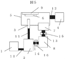
- It is a schematic diagram of the modification 1 of the structure preparation apparatus in Example 1.
- FIG. 5 is a schematic diagram of a structure manufacturing apparatus in Example 2.
- FIG. 1 is a schematic diagram of a structure manufacturing apparatus in Example 1.
- FIG. 1 shows a schematic diagram of a structure manufacturing apparatus in this example.
- the structure forming apparatus in this embodiment includes an aerosol generator 2 that disperses solid particles in a gas conveyed from a gas source 1 through a pipe 10 and a nozzle that injects solid particles in the aerosol conveyed through the pipe 11 onto a substrate 6. 3, the aerosol generator 2, the pipe 11, and the nozzle 3 are connected to each other, the vacuum pump 4 is connected through the pipe 12 and the internal pressure can be adjusted, and the solid ejected from the nozzle 3
- a particle recovery device 7 that recovers particles, and a crystallinity recovery processing unit 8 that is connected to the particle recovery device 7 by a pipe 13 and performs a crystallinity recovery process for recovering crystallinity of solid particles in the particle recovery device 7 are provided.
- the base material 6 is fixed by the substrate holder 9, and the structure forming portion on the substrate 6 can be controlled by changing the relative position of the base material 6 with respect to the nozzle 3.
- any method such as gravity dust collection, electric dust collection, centrifugal force dust collection, inertia force dust collection or the like can be used.
- the solid particles that have passed through the crystallinity recovery processing unit 8 are transported to the aerosol generator 2 through the pipe 14 and repeatedly used for structure formation.
- solid particles that have never been ejected from the nozzle 3 are referred to as raw material particles
- solid particles remaining in the structure forming chamber 5 after being ejected from the nozzle 3 are referred to as recovered particles.
- the recovered particles have an increased amount of strain in the particles due to the impact once on the base material 6 and have a lower crystallinity than the raw material particles.
- the material utilization efficiency is the weight ratio of the structure formed on the base material 6 to the weight of the particles colliding with the base material 6.
- the recovered particles recovered by the particle recovery apparatus 7 are subjected to a crystallinity recovery process in which the crystallinity recovery processing unit 8 recovers the crystallinity, thereby improving the crystallinity of the recovered particles. Even when the structure is formed using the recovered particles, the structure is not peeled off and the material utilization efficiency is not lowered.
- the half width of an X-ray diffraction peak can be used.
- X-ray diffraction of raw material particles, recovered particles that have not been subjected to crystallinity recovery processing before passing through the crystallinity recovery processing unit 8, and recovered particles that have passed through the crystallinity recovery processing unit 8 and have undergone crystallinity recovery processing Table 1 shows the half width of the peak and the material utilization efficiency.
- the solid particles were ⁇ -Al 2 O 3 having an average particle diameter of 2.8 ⁇ m as an example, and the half widths of diffraction peaks on the (012) plane were compared.
- the X-ray used for the measurement is CuK ⁇ ray, the measurement width is 0.0200 deg, the measurement speed is 50,000 deg / min, the divergence slit is 1.00 deg, the scattering slit is 1.00 deg, and the light receiving slit is 0.15 mm.
- heat treatment was performed at 600 ° C. for 1 hour in the air.
- the full width at half maximum of the recovered particles not subjected to the crystallinity recovery treatment is increased compared to the raw material particles, and both the crystallinity and the material utilization efficiency are decreased.
- the full width at half maximum of the recovered particles subjected to the crystallinity recovery treatment is equivalent to that of the raw material particles, and is recovered to the same degree of crystallinity as the raw material particles by the crystallinity recovery treatment.
- the material utilization efficiency is also the same as when raw material particles are used. From the above, it can be seen that the full width at half maximum of the X-ray diffraction peak of the recovered particles was reduced as compared with the raw material particles by the crystallinity recovery treatment.
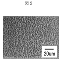
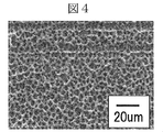
- FIGS. 2, 3, and 4 Surface SEM images of structures prepared using raw material particles, recovered particles not subjected to crystallinity recovery treatment, and recovered particles subjected to crystallinity recovery processing are shown in FIGS. 2, 3, and 4, respectively.
- FIG. 3 in the case of the recovered particles that have not been subjected to the crystallinity recovery treatment, the peeled portion is confirmed on the surface of the structure.
- FIG. 4 in the case of the recovered particles subjected to the crystallinity recovery treatment as shown in FIG. 4, there is no exfoliation site on the structure surface, and a surface structure equivalent to the case where the raw material particles shown in FIG. 2 are used is obtained.
- Any method such as resistance heating, induction heating, electron beam heating, thermal plasma heating, or laser beam heating can be used for the crystallinity recovery treatment as long as it is effective in recovering the crystallinity of the recovered particles.
- Raw material particles can be put into either the aerosol generator 2 or the crystallinity recovery processing unit 8, or both.
- the crystallinity recovery processing has an effect of removing moisture and organic substances on the surface of the raw material particles, so that the strength of the structure to be produced is improved. Impurities can be prevented from being mixed.
- valves 15 and 16 that can be opened and closed may be attached to the pipes 13 and 14, respectively. Since the gas pressure and gas type of the crystallinity recovery processing unit 8 can be controlled independently of the structure forming chamber 5 and the aerosol generator 2, crystallinity recovery processing according to the characteristics of the raw material powder can be performed. For example, when the solid particles are AlN, the oxidation or composition change of the solid particles can be prevented by performing in nitrogen or vacuum.
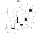
- the structure forming chamber 5 may be connected to a load lock chamber 17 connected to a vacuum pump and capable of adjusting pressure.
- the load lock chamber 17 is provided as a buffer between the outside and the structure forming chamber 5 so as not to open the structure forming chamber 5 to the atmosphere.
- the base material 6 is installed and taken out via the load lock chamber 17, and the load lock chamber is evacuated when the structure forming chamber 5 and the load lock chamber 17 communicate with each other. Thereby, since the structure forming chamber 5 is not opened to the atmosphere even when the base material 6 is installed or taken out, moisture and organic matter in the atmosphere remain in the structure forming chamber 5 and are prevented from being mixed into the structure as impurities. be able to.
- the crystallinity recovery processing unit 8 once collides with the base material 6 to recover the crystallinity of the recovered particles whose crystallinity is reduced, thereby suppressing the peeling of the structure and the decrease in material utilization efficiency. be able to.
- FIG. 7 shows a schematic diagram of the structure forming apparatus in the present embodiment.
- Example 2 an example of a structure forming apparatus in which an aggregate removal processing unit 18 is provided between the crystallinity recovery processing unit 8 and the aerosol generator 2 as compared with Example 1 will be described.
- Other configurations have the same functions as the configurations denoted by the same reference numerals shown in FIG. 1 and have not been described.
- an aggregate removal processing unit 18 that performs aggregate removal processing on the collected particles aggregated between the crystallinity recovery processing unit 8 and the aerosol generator 2 is provided.
- agglomerate removal treatment external force such as gravity or inertial force is applied to particles moving in the airflow
- a dry fluid classification process that separates particles according to the amount of deviation from the airflow streamline that changes according to the weight of the particles, and by passing the particles moving in the fluid through a filter with a certain opening, the size is smaller than the opening
- the particles are separated by agglomeration separation by filtering, etc. that allows only particles of the same size to pass, and by separating the particles according to the size of the particles, or by colliding the particles with media such as a ball mill or jet mill, and grinding the particles. Examples include crushing of aggregates by milling to reduce the size.
- the aggregate removal processing unit 18 separates and pulverizes the recovered particles aggregated inside the crystallinity recovery processing unit 8, thereby suppressing a decrease in structure strength and a decrease in material utilization efficiency. it can.
- this invention is not limited to the above-mentioned Example, Various modifications are included.
- the above-described embodiments have been described in detail for easy understanding of the present invention, and are not necessarily limited to those having all the configurations described.
- a part of the configuration of one embodiment can be replaced with the configuration of another embodiment, and the configuration of another embodiment can be added to the configuration of one embodiment.
Landscapes
- Other Surface Treatments For Metallic Materials (AREA)
- Physical Or Chemical Processes And Apparatus (AREA)
Abstract
本発明は、構造物形成室から回収した粒子で構造物を形成した場合でも構造物の剥離や材料利用効率の低下を抑制可能な構造物作製装置および方法を提供することを目的とする。 本発明は、ガス中に固体粒子を分散させるエアロゾル発生器と、前記エアロゾル発生器に接続された構造物形成室と、前記構造物形成室中に分散した固体粒子を回収する粒子回収装置と、前記エアロゾル発生器と前記粒子回収装置とに接続され、前記粒子回収装置で回収した固体粒子の結晶性を回復させる結晶性回復処理部とを備えることを特徴とする構造物作製装置を提供する。
Description
本発明は、構造物作製装置および構造物作製方法に関する。
本技術分野の背景技術として、特許第4311041号公報(特許文献1)がある。この公報には、粉体供給容器から供給された材料微粒子をガス中に分散させ、基板に衝突させたエアロゾルを吸引し、エアロゾル中の材料微粒子を捕捉し貯留する微粒子回収容器を備える複合構造物作製装置が記載されている。
他に本技術分野の背景技術として、特開2008-88559号公報(特許文献2)がある。この公報には、プラズマ照射またはマイクロ波照射により原料微粒子粉体の表面の付着物を除去する複合構造物作製装置が記載されている。
特許文献1では、エアロゾルデポジション法による構造物形成において、従来材料利用効率が著しく低いゆえに構造物形成室内に廃棄されていた材料粒子を粒子回収容器に貯留し、再利用することを可能としている。しかし、粒子回収容器に貯留された粒子を再び基板に衝突させ構造物を形成させる場合、基板に一度衝突した粒子の結晶性が低下することが考慮されていない。そのため、形成途中で構造物の一部に欠陥が生じる、材料利用効率が低下するといった課題がある。
特許文献2では、エアロゾルデポジション法による構造物形成において、プラズマ照射やマイクロ波照射により、材料粒子表面の付着物を除去することで、作製される構造物の強度向上を可能にしている。しかし、材料粒子表面の付着物を除去する程度のエネルギー照射では結晶性の回復には不十分である。そのため、構造物の一部が欠陥が生じる、材料利用効率が低下するといった課題がある。
上記問題点に鑑み、本発明は、構造物形成室から回収した粒子で構造物を形成した場合でも構造物に生じる欠陥や材料利用効率の低下を抑制可能な構造物作製装置および方法を提供することを目的とする。
上記課題を解決するために、例えば特許請求の範囲に記載の構成を採用する。
本発明はその一例を挙げるならば、ガス中に固体粒子を分散させるエアロゾル発生器と、前記エアロゾル発生器に接続された構造物形成室と、前記構造物形成室中に分散した固体粒子を回収する粒子回収装置と、前記エアロゾル発生器と前記粒子回収装置とに接続され、前記粒子回収装置で回収した固体粒子の結晶性を回復させる結晶性回復処理部とを備えることを特徴とする構造物作製装置を提供する。
本発明によれば、構造物形成室から回収した粒子で構造物を形成した場合でも構造物に生じる欠陥や材料利用効率の低下を抑制可能な構造物作製装置および方法を提供することができる。
以下、実施例を図面を用いて説明する。
図1に、本実施例における構造物作製装置の模式図を示す。
本実施例における構造物形成装置は、ガス源1から配管10を通して搬送したガス中に固体粒子を分散させるエアロゾル発生器2と、配管11を通して搬送したエアロゾル中の固体粒子を基板6に噴射するノズル3と、エアロゾル発生器2と配管11、ノズル3を解して接続され、配管12を通して真空ポンプ4が接続され内部の圧力調整が可能な構造物形成室5と、ノズル3から噴射された固体粒子を回収する粒子回収装置7と、粒子回収装置7と配管13で接続され粒子回収装置7内の固体粒子に結晶性を回復を行う結晶性回復処理を施す結晶性回復処理部8を有する。基材6は基板保持体9により固定されており、基板保持体9がノズル3に対する基材6の相対位置を変えることで、基板6上の構造物形成箇所を制御することができる。粒子回収装置7として、重力集塵、電気集塵、遠心力集塵、慣性力集塵などのいずれの方法も使用できる。結晶性回復処理部8を経た固体粒子は、配管14を通してエアロゾル発生器2に搬送され、繰り返し構造物形成に使用される。以下では、ノズル3から一度も噴射されていない固体粒子を原料粒子、ノズル3から噴射された後、構造物形成室5に残った固体粒子を回収粒子と記す。
回収粒子は、一度基材6に衝突した影響で粒子内の歪量が増加し、原料粒子に比べ結晶性が低下している。結晶性が低下した状態で回収粒子を構造物形成に使用した場合、構造物の剥離や材料利用効率の低下が生じる。材料利用効率とは、基材6に衝突した粒子重量に対する基材6に形成された構造物の重量比である。材料利用効率が低下すると、使用粒子量の増加、構造物形成時間の増加が必要となるため、構造物形成コストが増加する。
本実施例における構造物形成装置では、粒子回収装置7で回収された回収粒子に対して、結晶性回復処理部8で結晶性を回復させる結晶性回復処理を行うことで回収粒子の結晶性を回復させることができ、回収粒子を用いて構造物を形成した場合でも、構造物の剥離や材料利用効率の低下が生じない。
結晶性の評価方法として、例えばX線回折ピークの半値幅が利用できる。原料粒子、結晶性回復処理部8を通過する前であって結晶性回復処理を施していない回収粒子、結晶性回復処理部8を通過し、結晶性回復処理を施した回収粒子のX線回折ピークの半値幅と材料利用効率を表1に示す。

固体粒子は平均粒径2.8μmのα-Al2O3を例に、(012)面の回折ピークの半値幅を比較した。測定の使用したX線はCuKα線、測定幅は0.0200deg、測定速さは5.0000deg/min、発散スリットは1.00deg、散乱スリットは1.00deg、受光スリットは0.15mmである。結晶性回復処理として、大気中において600℃1時間の加熱処理を実施した。結晶性回復処理を施していない回収粒子の半値幅は、原料粒子に比べ増加し、結晶性と材料利用効率がともに低下している。一方、結晶性回復処理を施した回収粒子の半値幅は、原料粒子と同等であり、結晶性回復処理により原料粒子と同程度の結晶性に回復している。材料利用効率も原料粒子を用いた場合と同等である。以上より、結晶性回復処理により、回収粒子のX線回折ピークの半値幅が原料粒子よりも減少したことがわかる。
原料粒子、結晶性回復処理を施していない回収粒子、結晶性回復処理を施した回収粒子を用いて作製した構造物の表面SEM像をそれぞれ図2、図3、図4に示す。図3に示すように、結晶性回復処理を施していない回収粒子の場合、構造物表面に剥離箇所が確認される。一方、図4に示すように結晶性回復処理を施した回収粒子の場合、構造物表面に剥離箇所はなく、図2に示す原料粒子を用いた場合と同等の表面組織が得られる。
結晶性回復処理は回収粒子の結晶性を回復させる効果のある加熱処理であれば、抵抗加熱、誘導加熱、電子ビーム加熱、熱プラズマ加熱、レーザービーム加熱などのいずれの方法も使用できる。
原料粒子はエアロゾル発生器2または結晶性回復処理部8のいずれか、またはその両方に入れることができる。原料粒子を結晶性回復処理部8に入れ、結晶性回復処理を施した場合、結晶性回復処理が原料粒子表面の水分、有機物を除去する効果があるため、作製される構造物の強度向上、不純物の混入防止が可能である。
また図5に示す本実施例の変形例1のように、配管13、14にそれぞれ開閉可能な弁15、16がついていてもよい。結晶性回復処理部8のガス圧力やガス種を構造物形成室5やエアロゾル発生器2と独立して制御できるため、原料粉末の特性に応じた結晶性回復処理が可能になる。例えば、固体粒子をAlNとしたときに窒素中または真空中で行うことにより、固体粒子の酸化や組成変化を防止することができる。
また、図6に示す本実施例の変形例2のように、構造物形成室5には真空ポンプに接続され、圧力調整が可能なロードロック室17が接続されていてもよい。ロードロック室17は、構造物形成室5を大気開放させないために外部と構造物形成室5との間にバッファとして設けられたものである。基材6の設置や取出しをロードロック室17を介して行い、構造物形成室5とロードロック室17とが連通するときにロードロック室を真空にする。これにより、基材6の設置や取出しによっても構造物形成室5を大気開放されないため、大気中の水分や有機物が構造物形成室5内部に残留し、不純物として構造物に混入することを防ぐことができる。
本実施例によれば、結晶性回復処理部8により一度基材6に衝突して結晶性の低下した回収粒子の結晶性を回復させることで構造物の剥離や材料利用効率の低下を抑制させることができる。
図7に本実施例における構造物形成装置の模式図を示す。
本実施例では、実施例1と比較して、結晶性回復処理部8とエアロゾル発生器2との間に凝集体除去処理部18を設けた構造物形成装置の例を説明する。その他構成は、既に説明した図1に示された同一の符号を付された構成と、同一の機能を有するので、それらの説明は省略する。
固体粒子の材料によっては、粒子回収装置7や結晶性回復処理部8の内部において回収粒子同士が接触すると、回収粒子が凝集体となる場合がある。凝集体を含んだ固体粒子を構造物形成に用いると、構造物の強度低下や材料利用効率低下を引き起こすため、凝集体を取り除く必要がある。そこで、本実施例では、結晶性回復処理部8とエアロゾル発生器2との間に凝集した回収粒子に対して凝集体除去処理を施す凝集体除去処理部18を設けた。
凝集体除去処理としては、気流中で運動する粒子に重力などの外力や慣性力を作用させ、
粒子の重量に応じて変化する気流流線からのずれの大小で粒子を分離する乾式流体分級処理、流体中で運動する粒子をある目開きをもったフィルタに通すことで、目開き以下の大きさの粒子のみを通過させ、粒子の大きさに応じて粒子を分離するフィルタ処理などによる凝集体の分離や、ボールミル、ジェットミルといったメディアと粒子を衝突させ、粒子を磨砕することで粒子の大きさを小さくするミル処理による凝集体の破砕が挙げられる。
粒子の重量に応じて変化する気流流線からのずれの大小で粒子を分離する乾式流体分級処理、流体中で運動する粒子をある目開きをもったフィルタに通すことで、目開き以下の大きさの粒子のみを通過させ、粒子の大きさに応じて粒子を分離するフィルタ処理などによる凝集体の分離や、ボールミル、ジェットミルといったメディアと粒子を衝突させ、粒子を磨砕することで粒子の大きさを小さくするミル処理による凝集体の破砕が挙げられる。
本実施例によれば、凝集体除去処理部18によって結晶性回復処理部8の内部で凝集した回収粒子を分離・粉砕することで構造物の強度低下や材料利用効率の低下を抑制することができる。
なお、本発明は上記した実施例に限定されるものではなく、様々な変形例が含まれる。例えば、上記した実施例は本発明を分かりやすく説明するために詳細に説明したものであり、必ずしも説明した全ての構成を備えるものに限定されるものではない。また、ある実施例の構成の一部を他の実施例の構成に置き換えることが可能であり、また、ある実施例の構成に他の実施例の構成を加えることも可能である。また、各実施例の構成の一部について、他の構成の追加・削除・置換をすることが可能である。
1 ガス源
2 エアロゾル発生器
3 ノズル
4 真空ポンプ
5 構造物形成室
6 基材
7 粒子回収装置
8 結晶性回復処理部
9 基板保持体
10、11、12、13、14 配管
15、16 弁
17 ロードロック室
18 凝集体除去処理部
2 エアロゾル発生器
3 ノズル
4 真空ポンプ
5 構造物形成室
6 基材
7 粒子回収装置
8 結晶性回復処理部
9 基板保持体
10、11、12、13、14 配管
15、16 弁
17 ロードロック室
18 凝集体除去処理部
Claims (14)
- ガス中に固体粒子を分散させるエアロゾル発生器と、
前記エアロゾル発生器に接続された構造物形成室と、
前記構造物形成室中に分散した固体粒子を回収する粒子回収装置と、
前記エアロゾル発生器と前記粒子回収装置とに接続され、前記粒子回収装置で回収した固体粒子の結晶性を回復させる結晶性回復処理部とを備えることを特徴とする構造物作製装置。 - 前記結晶性回復処理部を通過した固体粒子のX線回折ピークの半値幅は前記結晶性回復処理部を通過する前の固体粒子のX線回折ピークの半値幅よりも減少していることを特徴とする請求項1に記載の構造物作製装置。
- 前記粒子回収装置と前記結晶性回復処理部の間及び前記結晶性回復処理部と前記エアロゾル発生器の間にそれぞれ開閉可能な弁を備えることを特徴とする請求項1に記載の構造物作製装置。
- 前記結晶性回復処理は加熱処理であることを特徴とする請求項1に記載の構造物作製装置。
- 前記結晶性回復処理部と前記エアロゾル発生器との間に固体粒子の凝集体除去処理を施す凝集体除去処理部を備えることを請求項1に記載の特徴とする構造物作製装置。
- 前記凝集体除去処理は、乾式流体分級処理、フィルタ処理、ミル処理の少なくともいずれか1つを含むことを特徴とする請求項5に記載の構造物作製装置。
- 外部と前記構造物形成室との間に接続され、圧力制御が可能なロードロック室を備えることを特徴とする請求項1に記載の構造物作製装置。
- ガス中に固体粒子を分散させ、
前記固体粒子を構造物形成室中にある基板に噴射し、
前記構造物形成室中の固体粒子を回収し、
回収した前記固体粒子に結晶性を回復させる結晶性回復処理を施し、
結晶性回復処理を施した前記固体粒子を前記基板に噴射することを特徴とする構造物作製方法。 - 結晶性回復処理を施された固体粒子のX線回折ピークの半値幅結晶性回復処理を施される前の固体粒子のX線回折ピークの半値幅よりも減少していることを特徴とする請求項8に記載の構造物作製方法。
- 前記結晶性回復処理におけるガス圧力またはガス種を前記構造物形成室とは独立して制御することを特徴とする請求項8に記載の構造物作製方法。
- 前記結晶性回復処理は加熱処理であることを特徴とする請求項8に記載の構造物作製方法。
- 結晶性回復処理を施した前記固体粒子に凝集体除去処理を施すことを特徴とする請求項8に記載の構造物作製方法。
- 前記凝集体除去処理は、乾式流体分級処理、フィルタ処理、ミル処理の少なくともいずれか1つを含むことを特徴とする請求項12に記載の構造物作製方法。
- 前記構造物形成室を真空にすることを特徴とする請求項8に記載の構造物作成方法。
Applications Claiming Priority (2)
| Application Number | Priority Date | Filing Date | Title |
|---|---|---|---|
| JP2013013839A JP2014145103A (ja) | 2013-01-29 | 2013-01-29 | 構造物作製装置および構造物作製方法 |
| JP2013-013839 | 2013-01-29 |
Publications (1)
| Publication Number | Publication Date |
|---|---|
| WO2014119084A1 true WO2014119084A1 (ja) | 2014-08-07 |
Family
ID=51261816
Family Applications (1)
| Application Number | Title | Priority Date | Filing Date |
|---|---|---|---|
| PCT/JP2013/080179 Ceased WO2014119084A1 (ja) | 2013-01-29 | 2013-11-08 | 構造物作製装置および構造物作製方法 |
Country Status (2)
| Country | Link |
|---|---|
| JP (1) | JP2014145103A (ja) |
| WO (1) | WO2014119084A1 (ja) |
Citations (3)
| Publication number | Priority date | Publication date | Assignee | Title |
|---|---|---|---|---|
| JP2004265992A (ja) * | 2003-02-28 | 2004-09-24 | Toto Ltd | 複合構造物作製装置 |
| JP2007119913A (ja) * | 2005-09-30 | 2007-05-17 | Fujifilm Corp | 複合構造物の製造方法、不純物除去処理装置、成膜装置、複合構造物、及び、原料粉 |
| JP2012207294A (ja) * | 2011-03-30 | 2012-10-25 | Toto Ltd | 構造物形成方法 |
-
2013
- 2013-01-29 JP JP2013013839A patent/JP2014145103A/ja active Pending
- 2013-11-08 WO PCT/JP2013/080179 patent/WO2014119084A1/ja not_active Ceased
Patent Citations (3)
| Publication number | Priority date | Publication date | Assignee | Title |
|---|---|---|---|---|
| JP2004265992A (ja) * | 2003-02-28 | 2004-09-24 | Toto Ltd | 複合構造物作製装置 |
| JP2007119913A (ja) * | 2005-09-30 | 2007-05-17 | Fujifilm Corp | 複合構造物の製造方法、不純物除去処理装置、成膜装置、複合構造物、及び、原料粉 |
| JP2012207294A (ja) * | 2011-03-30 | 2012-10-25 | Toto Ltd | 構造物形成方法 |
Also Published As
| Publication number | Publication date |
|---|---|
| JP2014145103A (ja) | 2014-08-14 |
Similar Documents
| Publication | Publication Date | Title |
|---|---|---|
| US10307763B2 (en) | Polycrystalline silicon fragment, method for manufacturing polycrystalline silicon fragment, and polycrystalline silicon block fracture device | |
| CN105668554B (zh) | 一种利用气流剥离分级制备石墨烯微片的方法 | |
| CN102909383B (zh) | 超细镍粉或钴粉的制备方法 | |
| CN107470639B (zh) | 一种窄粒度分布球形钨粉的制备方法 | |
| JP7438305B2 (ja) | 銀粉 | |
| WO2014119084A1 (ja) | 構造物作製装置および構造物作製方法 | |
| JP4092568B2 (ja) | 微粉末ケイ素又はケイ素化合物の製造方法 | |
| JP7650325B2 (ja) | 銀粉及び導電性ペースト | |
| CN106458628B (zh) | 金属复合氧化物微粒子及其制造方法 | |
| CN1958446A (zh) | 一种用天然石英粉制备高纯超细硅微粉的方法 | |
| CN105381665A (zh) | 一种冶炼烟尘高温分级过滤的处理方法 | |
| JP2011156520A (ja) | 金属微粉の分級方法 | |
| JP7442288B2 (ja) | セラミックス粉末 | |
| CN102114544A (zh) | 一种制备粒径分布均匀且球形度和分散性好的钨粉的方法 | |
| JP2022140325A (ja) | 銀粉及びその製造方法 | |
| JP2012207294A (ja) | 構造物形成方法 | |
| JP7375245B1 (ja) | 銀粉の製造方法 | |
| WO2025089239A1 (ja) | 銀粉及び銀粉の製造方法並びに導電性ペースト | |
| US20260097966A1 (en) | Methods of producing anode active materials and graphene from graphite | |
| EP3060357A1 (en) | Method and system for cleaning contaminated silicon carbide particles | |
| JPH04225074A (ja) | 黒鉛化度を増大させたカーボンブラックの製造方法 | |
| JP6058610B2 (ja) | 多結晶シリコン破砕物、多結晶シリコン破砕物の製造方法および多結晶シリコン塊破砕装置 | |
| KR102093293B1 (ko) | 진공기공을 갖는 나노입자 구조체 | |
| TWM675649U (zh) | 由水刀切割耗材之廢砂回收鐵物質製成氧化鐵的製備系統 | |
| CN117264444A (zh) | 炭黑制备工艺及炭黑加工设备 |
Legal Events
| Date | Code | Title | Description |
|---|---|---|---|
| 121 | Ep: the epo has been informed by wipo that ep was designated in this application |
Ref document number: 13873898 Country of ref document: EP Kind code of ref document: A1 |
|
| NENP | Non-entry into the national phase |
Ref country code: DE |
|
| 122 | Ep: pct application non-entry in european phase |
Ref document number: 13873898 Country of ref document: EP Kind code of ref document: A1 |