WO2014118906A1 - 油圧システム、風力発電装置及びそれらの制御方法 - Google Patents
油圧システム、風力発電装置及びそれらの制御方法 Download PDFInfo
- Publication number
- WO2014118906A1 WO2014118906A1 PCT/JP2013/051996 JP2013051996W WO2014118906A1 WO 2014118906 A1 WO2014118906 A1 WO 2014118906A1 JP 2013051996 W JP2013051996 W JP 2013051996W WO 2014118906 A1 WO2014118906 A1 WO 2014118906A1
- Authority
- WO
- WIPO (PCT)
- Prior art keywords
- hydraulic machine
- hydraulic
- pistons
- phase
- machine
- Prior art date
- Legal status (The legal status is an assumption and is not a legal conclusion. Google has not performed a legal analysis and makes no representation as to the accuracy of the status listed.)
- Ceased
Links
Images







Classifications
-
- F—MECHANICAL ENGINEERING; LIGHTING; HEATING; WEAPONS; BLASTING
- F03—MACHINES OR ENGINES FOR LIQUIDS; WIND, SPRING, OR WEIGHT MOTORS; PRODUCING MECHANICAL POWER OR A REACTIVE PROPULSIVE THRUST, NOT OTHERWISE PROVIDED FOR
- F03C—POSITIVE-DISPLACEMENT ENGINES DRIVEN BY LIQUIDS
- F03C1/00—Reciprocating-piston liquid engines
- F03C1/02—Reciprocating-piston liquid engines with multiple-cylinders, characterised by the number or arrangement of cylinders
- F03C1/04—Reciprocating-piston liquid engines with multiple-cylinders, characterised by the number or arrangement of cylinders with cylinders in star or fan arrangement
- F03C1/053—Reciprocating-piston liquid engines with multiple-cylinders, characterised by the number or arrangement of cylinders with cylinders in star or fan arrangement the pistons co-operating with an actuated element at the inner ends of the cylinders
-
- F—MECHANICAL ENGINEERING; LIGHTING; HEATING; WEAPONS; BLASTING
- F03—MACHINES OR ENGINES FOR LIQUIDS; WIND, SPRING, OR WEIGHT MOTORS; PRODUCING MECHANICAL POWER OR A REACTIVE PROPULSIVE THRUST, NOT OTHERWISE PROVIDED FOR
- F03D—WIND MOTORS
- F03D13/00—Assembly, mounting or commissioning of wind motors; Arrangements specially adapted for transporting wind motor components
- F03D13/20—Arrangements for mounting or supporting wind motors; Masts or towers for wind motors
-
- F—MECHANICAL ENGINEERING; LIGHTING; HEATING; WEAPONS; BLASTING
- F03—MACHINES OR ENGINES FOR LIQUIDS; WIND, SPRING, OR WEIGHT MOTORS; PRODUCING MECHANICAL POWER OR A REACTIVE PROPULSIVE THRUST, NOT OTHERWISE PROVIDED FOR
- F03C—POSITIVE-DISPLACEMENT ENGINES DRIVEN BY LIQUIDS
- F03C1/00—Reciprocating-piston liquid engines
- F03C1/26—Reciprocating-piston liquid engines adapted for special use or combined with apparatus driven thereby
-
- F—MECHANICAL ENGINEERING; LIGHTING; HEATING; WEAPONS; BLASTING
- F04—POSITIVE - DISPLACEMENT MACHINES FOR LIQUIDS; PUMPS FOR LIQUIDS OR ELASTIC FLUIDS
- F04B—POSITIVE-DISPLACEMENT MACHINES FOR LIQUIDS; PUMPS
- F04B1/00—Multi-cylinder machines or pumps characterised by number or arrangement of cylinders
- F04B1/04—Multi-cylinder machines or pumps characterised by number or arrangement of cylinders having cylinders in star- or fan-arrangement
- F04B1/0404—Details or component parts
- F04B1/0426—Arrangements for pressing the pistons against the actuated cam; Arrangements for connecting the pistons to the actuated cam
-
- F—MECHANICAL ENGINEERING; LIGHTING; HEATING; WEAPONS; BLASTING
- F04—POSITIVE - DISPLACEMENT MACHINES FOR LIQUIDS; PUMPS FOR LIQUIDS OR ELASTIC FLUIDS
- F04B—POSITIVE-DISPLACEMENT MACHINES FOR LIQUIDS; PUMPS
- F04B1/00—Multi-cylinder machines or pumps characterised by number or arrangement of cylinders
- F04B1/04—Multi-cylinder machines or pumps characterised by number or arrangement of cylinders having cylinders in star- or fan-arrangement
- F04B1/053—Multi-cylinder machines or pumps characterised by number or arrangement of cylinders having cylinders in star- or fan-arrangement with actuating or actuated elements at the inner ends of the cylinders
-
- F—MECHANICAL ENGINEERING; LIGHTING; HEATING; WEAPONS; BLASTING
- F04—POSITIVE - DISPLACEMENT MACHINES FOR LIQUIDS; PUMPS FOR LIQUIDS OR ELASTIC FLUIDS
- F04B—POSITIVE-DISPLACEMENT MACHINES FOR LIQUIDS; PUMPS
- F04B17/00—Pumps characterised by combination with, or adaptation to, specific driving engines or motors
- F04B17/02—Pumps characterised by combination with, or adaptation to, specific driving engines or motors driven by wind motors
-
- F—MECHANICAL ENGINEERING; LIGHTING; HEATING; WEAPONS; BLASTING
- F05—INDEXING SCHEMES RELATING TO ENGINES OR PUMPS IN VARIOUS SUBCLASSES OF CLASSES F01-F04
- F05B—INDEXING SCHEME RELATING TO WIND, SPRING, WEIGHT, INERTIA OR LIKE MOTORS, TO MACHINES OR ENGINES FOR LIQUIDS COVERED BY SUBCLASSES F03B, F03D AND F03G
- F05B2240/00—Components
- F05B2240/10—Stators
- F05B2240/14—Casings, housings, nacelles, gondels or the like, protecting or supporting assemblies there within
-
- F—MECHANICAL ENGINEERING; LIGHTING; HEATING; WEAPONS; BLASTING
- F05—INDEXING SCHEMES RELATING TO ENGINES OR PUMPS IN VARIOUS SUBCLASSES OF CLASSES F01-F04
- F05B—INDEXING SCHEME RELATING TO WIND, SPRING, WEIGHT, INERTIA OR LIKE MOTORS, TO MACHINES OR ENGINES FOR LIQUIDS COVERED BY SUBCLASSES F03B, F03D AND F03G
- F05B2260/00—Function
- F05B2260/40—Transmission of power
- F05B2260/406—Transmission of power through hydraulic systems
-
- F—MECHANICAL ENGINEERING; LIGHTING; HEATING; WEAPONS; BLASTING
- F05—INDEXING SCHEMES RELATING TO ENGINES OR PUMPS IN VARIOUS SUBCLASSES OF CLASSES F01-F04
- F05B—INDEXING SCHEME RELATING TO WIND, SPRING, WEIGHT, INERTIA OR LIKE MOTORS, TO MACHINES OR ENGINES FOR LIQUIDS COVERED BY SUBCLASSES F03B, F03D AND F03G
- F05B2260/00—Function
- F05B2260/96—Preventing, counteracting or reducing vibration or noise
- F05B2260/964—Preventing, counteracting or reducing vibration or noise by damping means
-
- Y—GENERAL TAGGING OF NEW TECHNOLOGICAL DEVELOPMENTS; GENERAL TAGGING OF CROSS-SECTIONAL TECHNOLOGIES SPANNING OVER SEVERAL SECTIONS OF THE IPC; TECHNICAL SUBJECTS COVERED BY FORMER USPC CROSS-REFERENCE ART COLLECTIONS [XRACs] AND DIGESTS
- Y02—TECHNOLOGIES OR APPLICATIONS FOR MITIGATION OR ADAPTATION AGAINST CLIMATE CHANGE
- Y02E—REDUCTION OF GREENHOUSE GAS [GHG] EMISSIONS, RELATED TO ENERGY GENERATION, TRANSMISSION OR DISTRIBUTION
- Y02E10/00—Energy generation through renewable energy sources
- Y02E10/70—Wind energy
- Y02E10/72—Wind turbines with rotation axis in wind direction
-
- Y—GENERAL TAGGING OF NEW TECHNOLOGICAL DEVELOPMENTS; GENERAL TAGGING OF CROSS-SECTIONAL TECHNOLOGIES SPANNING OVER SEVERAL SECTIONS OF THE IPC; TECHNICAL SUBJECTS COVERED BY FORMER USPC CROSS-REFERENCE ART COLLECTIONS [XRACs] AND DIGESTS
- Y02—TECHNOLOGIES OR APPLICATIONS FOR MITIGATION OR ADAPTATION AGAINST CLIMATE CHANGE
- Y02E—REDUCTION OF GREENHOUSE GAS [GHG] EMISSIONS, RELATED TO ENERGY GENERATION, TRANSMISSION OR DISTRIBUTION
- Y02E10/00—Energy generation through renewable energy sources
- Y02E10/70—Wind energy
- Y02E10/728—Onshore wind turbines
Definitions
- the present disclosure relates to a hydraulic system, a wind power generator, and control methods thereof.
- a wind turbine generator generally includes a nacelle supported by a tower, a wing, and a main shaft supported by the nacelle so as to be rotatable together with the wing.
- the wind force received by the blades is converted into the rotational force of the main shaft, and this rotational force is input to the generator via the speed increasing mechanism installed in the nacelle and converted into electric power.
- the hydraulic transmission is configured by combining a hydraulic pump and a hydraulic motor.
- the hydraulic pump and the hydraulic motor are configured by a radial piston type hydraulic machine, and in the hydraulic machine, a plurality of cylinders and a plurality of pistons are arranged in the circumferential direction of the rotating shaft.
- the plurality of cylinders and the plurality of pistons respectively form a plurality of working chambers, and the volume of each working chamber increases and decreases with the reciprocating motion of each piston.
- the reciprocating motion of the piston and the rotational motion of the rotating shaft can be converted into each other by a motion mode conversion mechanism.
- the hydraulic machine is provided with a plurality of oil supply valves for controlling the supply of hydraulic oil to the plurality of working chambers and a drain valve for controlling the discharge of hydraulic oil from the plurality of working chambers. ing.
- a variable capacity hydraulic pump and a hydraulic pump are used. Specifically, in the case of a hydraulic pump, by keeping the oil supply valve (low pressure valve) open, the working chamber can be brought into a non-operating state that does not contribute to the compression of the working oil. The capacity can be adjusted by adjusting the number. In the case of a hydraulic motor, by closing the oil supply valve (high pressure valve) and keeping the oil discharge valve (low pressure valve) open, the working chamber is brought into a non-operating state that does not contribute to driving the rotating shaft. The volume can be adjusted by adjusting the number of non-actuated working chambers.
- Patent Document 3 discloses a layout example of a hydraulic pump and a hydraulic motor in the nacelle.
- the hydraulic pump is arranged coaxially with the main shaft, and two hydraulic motors are arranged on both sides of the hydraulic pump.
- the radial piston type hydraulic machine used for the speed increasing mechanism generates relatively large vibrations and operation sounds.
- the operation sound of the wind power generator also increases.
- An object of at least one embodiment of the present invention is to provide a hydraulic system, a wind power generation apparatus, and a control method thereof that are excellent in quietness, in which vibrations and operation noise resulting from the operation of a hydraulic machine are suppressed.
- a hydraulic system includes: A first radial piston type hydraulic machine mounted on the structure; A radial piston type second hydraulic machine mounted on the structure, Each of the first hydraulic machine and the second hydraulic machine is A rotation axis; A plurality of cylinders arranged at least in the circumferential direction of the rotating shaft; A plurality of pistons forming a plurality of working chambers together with the plurality of cylinders; The phase of the reciprocating motion of the plurality of pistons in the first hydraulic machine and the second hydraulic machine is set so as to suppress vibration of the structure.
- each of the first hydraulic machine and the second hydraulic machine vibrates due to the reciprocating motion of the piston, and the vibration is applied to the structure.
- the first hydraulic machine and the second hydraulic machine since the phase of the reciprocating motion of the piston is set so as to suppress the vibration of the structure, the first hydraulic machine and the second hydraulic machine vibrate. Even so, the vibration of the structure is suppressed. As a result, the vibration of the structure is suppressed, and the vibration and operation sound of the hydraulic system are suppressed.
- the phase of the reciprocating motion of the plurality of pistons in the first hydraulic machine and the second hydraulic machine suppresses vibration of the structure due to a natural vibration mode of the structure. It is set as follows.
- the structure in which the first hydraulic machine and the second hydraulic machine are installed has a unique vibration mode depending on the structure.
- the structure vibrates in the natural vibration mode, and the vibration propagates to the entire hydraulic system.
- each of the first hydraulic machine and the second hydraulic machine vibrates due to the reciprocating motion of the piston, and the vibration is applied to the structure.
- the phase of the reciprocating motion of the piston is set so as to suppress the vibration of the structure due to the natural vibration mode of the structure. Even if the machine and the second hydraulic machine vibrate, the vibration of the structure in the natural vibration mode is suppressed. As a result, the vibration of the structure is suppressed from propagating to the entire wind power generator, and the vibration and operation noise of the wind power generator are suppressed.
- the first hydraulic machine and the second hydraulic machine are arranged symmetrically about a virtual mirror surface.
- the vibration of the structure caused by the vibration of the first hydraulic machine can be accurately canceled and suppressed by the vibration of the second hydraulic machine.
- the vibration of the structure caused by the vibration of the second hydraulic machine can be accurately canceled and suppressed by the vibration of the first hydraulic machine.
- the rotational direction of the rotary shaft of the second hydraulic machine is configured to be opposite to the rotational direction of the rotary shaft of the first hydraulic machine
- the reciprocating motion of the plurality of pistons in the first hydraulic machine is substantially the same as the plurality of pistons in the second hydraulic machine having a mirror symmetry with the plurality of pistons in the first hydraulic machine.
- the phase of the reciprocating motion of the plurality of pistons in the first hydraulic machine and the second hydraulic machine is set so as to reciprocate in phase.
- the natural vibration mode of the structure includes an in-phase natural vibration mode in which the vibration direction is the same at the installation positions of the first hydraulic machine and the second hydraulic machine, and a reverse phase vibration mode in which the vibration direction is opposite. is there.
- the first hydraulic machine has a mirror-symmetric relationship with the piston of the first hydraulic machine.
- the vibration of the structure can be accurately canceled and suppressed by the reciprocating motion of the piston in a certain second hydraulic machine. The reverse is also true.
- the rotational direction of the rotary shaft of the second hydraulic machine is configured to be the same as the rotational direction of the rotary shaft of the first hydraulic machine, and The first hydraulic machine and the first hydraulic machine so that the plurality of pistons in the second hydraulic machine reciprocate with a phase difference of about 180 degrees with respect to the reciprocating movement of the plurality of pistons in the first hydraulic machine.
- a phase of reciprocating motion of the plurality of pistons in the second hydraulic machine is set.
- the plurality of pistons in the first hydraulic machine reciprocate with a phase difference of 180 degrees with respect to the plurality of pistons in the first hydraulic machine.
- the movement directions of the plurality of pistons in the second hydraulic machine are opposite to the movement direction. For this reason, even if the plurality of pistons reciprocate in the first hydraulic machine and cause vibration of the structure in the natural vibration mode of the opposite phase, the piston reciprocates in the second hydraulic machine. Vibrations can be accurately canceled and suppressed. The reverse is also true.
- the rotational direction of the rotary shaft of the second hydraulic machine is configured to be the same as the rotational direction of the rotary shaft of the first hydraulic machine, and
- the first hydraulic machine and the second hydraulic machine are configured so that the plurality of pistons in the second hydraulic machine reciprocate in substantially the same phase with respect to the reciprocating movement of the plurality of pistons in the first hydraulic machine.
- the phase of the reciprocating motion of the plurality of pistons in the hydraulic machine is set.
- the wind turbine generator further includes a controller for controlling the first hydraulic machine and the second hydraulic machine,
- Each of the first hydraulic machine and the second hydraulic machine is: A plurality of oil supply valves for respectively controlling the supply of hydraulic oil to the plurality of working chambers; A plurality of oil discharge valves for controlling discharge of hydraulic oil from the plurality of working chambers, Further comprising
- the control device controls the first hydraulic pressure by controlling at least the plurality of oil supply valves among the plurality of oil supply valves and the plurality of oil discharge valves in the first hydraulic machine and the second hydraulic machine.
- the reciprocating motion of the plurality of pistons in the machine and the second hydraulic machine is configured to match a set phase.
- the control device controls at least the oil supply valve
- the phase of the reciprocating motion of the piston in the first hydraulic machine and the second hydraulic machine is matched with the set phase, and the vibration of the structure is accurately detected. It can be countered and suppressed.
- the setting of the phase to be matched can be changed as appropriate in response to the natural vibration mode that actually causes the vibration of the structure, and the vibration of the structure is accurately canceled and suppressed. be able to.
- the controller is By controlling at least the plurality of oil supply valves among the plurality of oil supply valves and the plurality of oil discharge valves in the first hydraulic machine and the second hydraulic machine, the states of the plurality of operation chambers are operated. Switchable between a state and a non-operating state, and When switching the state of at least one working chamber in the first hydraulic machine, switching the state of at least one working chamber in the second hydraulic machine so as to suppress vibration of the structure. Is configured to do.
- the first hydraulic machine and the second hydraulic machine are operated not only when all the working chambers are operating at full load, but also when some of the working chambers are not operating. Even when operating with a partial load, the vibration of the structure can be accurately canceled and suppressed.
- the controller is When switching the state of at least one of the working chambers in the first hydraulic machine to a non-operating state, the at least one working chamber in the second hydraulic machine is inoperative in the first hydraulic machine
- the state of the working chamber formed by the piston that reciprocates in the same phase as the piston that forms the working chamber that is switched to a state is switched to a non-operating state.
- the controller is When switching the state of at least one of the working chambers in the first hydraulic machine to a non-operating state, the at least one working chamber in the second hydraulic machine is inoperative in the first hydraulic machine
- the state of the working chamber formed by the piston that reciprocates in a phase opposite to that of the piston that forms the working chamber that is switched to a state is switched to a non-operating state.
- a wind turbine generator according to at least one embodiment of the present invention, A nacelle supported by a tower, At least one wing, A main shaft supported by the nacelle rotatably with the wing; A hydraulic pump disposed within the nacelle and configured to be driven by rotation of the main shaft; A hydraulic motor disposed in the nacelle and configured to be driven by pressure oil generated by the hydraulic pump; A generator configured to be driven by the hydraulic motor; A wind turbine generator comprising: One of the hydraulic pump and the hydraulic motor includes a first hydraulic machine and a second hydraulic machine of a radial piston type, Each of the first hydraulic machine and the second hydraulic machine is A rotation axis; A plurality of cylinders arranged at least in the circumferential direction of the rotating shaft; In a control method of a wind turbine generator having a plurality of pistons that form a plurality of working chambers together with the plurality of cylinders, The phase of the reciprocating motion of the plurality of pistons in the first hydraulic machine and the second hydraulic machine is set so as to suppress the vibration
- each of the first hydraulic machine and the second hydraulic machine vibrates by the reciprocating motion of the piston, and the vibration is applied to the nacelle.
- the first hydraulic machine and the second hydraulic machine since the phase of the reciprocating motion of the piston is set so as to suppress the vibration of the nacelle, the first hydraulic machine and the second hydraulic machine vibrated.
- the vibration of the nacelle is suppressed.
- the vibration of the nacelle is suppressed from propagating to the entire wind power generator, and the vibration and operation noise of the wind power generator are suppressed.
- the nacelle in which the first hydraulic machine and the second hydraulic machine are installed has a unique vibration mode depending on its structure.
- the nacelle vibrates in the natural vibration mode, and the vibration propagates to the entire wind power generator.
- each of the first hydraulic machine and the second hydraulic machine vibrates by the reciprocating motion of the piston, and the vibration is applied to the nacelle.
- the phase of the reciprocating motion of the piston is set so as to suppress the nacelle vibration caused by the natural vibration mode of the nacelle. Even if the second hydraulic machine vibrates, the vibration of the nacelle in the natural vibration mode is suppressed. As a result, the vibration of the nacelle is suppressed from propagating to the entire wind power generator, and the vibration and operation noise of the wind power generator are suppressed.
- the first hydraulic machine and the second hydraulic machine are the hydraulic motors; In the nacelle, the first hydraulic machine and the second hydraulic machine are arranged symmetrically about a virtual mirror surface including the axis of the main shaft and a vertical axis.
- the vibration of the nacelle caused by the vibration of the first hydraulic machine can be accurately canceled and suppressed by the vibration of the second hydraulic machine.
- the nacelle vibration caused by the vibration of the second hydraulic machine can be accurately canceled and suppressed by the vibration of the first hydraulic machine.
- a control method of a hydraulic system includes: A first radial piston type hydraulic machine mounted on the structure; A radial piston type second hydraulic machine mounted on the structure, Each of the first hydraulic machine and the second hydraulic machine is A rotation axis; A plurality of cylinders arranged at least in the circumferential direction of the rotating shaft; In a control method of a hydraulic system having a plurality of pistons that form a plurality of working chambers together with the plurality of cylinders, A setting step of setting a phase of reciprocating motion of the plurality of pistons in the first hydraulic machine and the second hydraulic machine so as to suppress vibration of the structure.
- the phase of the reciprocating motion of the piston is set so as to suppress the vibration of the structure. Even if the second hydraulic machine vibrates, the vibration of the structure is suppressed. As a result, the vibration of the structure is suppressed from propagating to the entire hydraulic system, and the vibration and operation noise of the hydraulic system are suppressed.
- a method for controlling a wind turbine generator includes: A nacelle supported by the tower; At least one wing, A main shaft supported by the nacelle rotatably with the wing; A hydraulic pump disposed within the nacelle and configured to be driven by rotation of the main shaft; A hydraulic motor disposed in the nacelle and configured to be driven by pressure oil generated by the hydraulic pump; A generator configured to be driven by the hydraulic motor; A method for controlling a wind turbine generator comprising: One of the hydraulic pump and the hydraulic motor includes a first hydraulic machine and a second hydraulic machine of a radial piston type, Each of the first hydraulic machine and the second hydraulic machine is A rotation axis; A plurality of cylinders arranged at least in the circumferential direction of the rotating shaft; In a control method of a wind turbine generator having a plurality of pistons that form a plurality of working chambers together with the plurality of cylinders, A setting step of setting a phase of reciprocation of the plurality of pistons in the first hydraulic machine
- the phase of the reciprocating motion of the piston is set so as to suppress the vibration of the nacelle. Even if the second hydraulic machine vibrates, the vibration of the nacelle is suppressed. As a result, the vibration of the nacelle is suppressed from propagating to the entire wind power generator, and the vibration and operation noise of the wind power generator are suppressed.
- a hydraulic system, a wind power generation apparatus, and a control method thereof that are excellent in noise reduction due to suppression of vibration and operation noise caused by operation of a hydraulic machine.
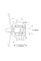
- FIG. 1 It is a side view which shows roughly the structure of the air volume power generation apparatus which concerns on some embodiment of this invention. It is a top view which shows schematically the structure of the wind power generator of FIG. It is a cross-sectional view which shows roughly the structure of the 1st hydraulic motor (2nd hydraulic motor) applied to the wind power generator of FIG. It is a figure for demonstrating an example of the vibration of the nacelle in arrangement
- FIG. 1 is a side view schematically showing the configuration of a wind turbine generator according to some embodiments of the present invention
- FIG. 2 is a top view schematically showing the configuration of the wind turbine generator.
- the wind turbine generator is capable of rotating together with a tower 10, a nacelle 12 supported by the tower 10, a main shaft 14 rotatably supported by the nacelle 12, and the main shaft 14.
- At least one blade 16 a hydraulic pump 18 disposed in the nacelle 12 and configured to be driven by the rotation of the main shaft 14, and pressure oil disposed in the nacelle 12 and generated by the hydraulic pump 18
- a hydraulic motor 20 configured to be driven by the hydraulic motor 20 and a generator 22 configured to be driven by the hydraulic motor 20.
- One of the hydraulic pump 18 and the hydraulic motor 20 includes a radial piston type first hydraulic machine and a second hydraulic machine.
- the hydraulic motor 20 includes a first hydraulic machine (first hydraulic motor 20A) and a second hydraulic machine (second hydraulic motor 20B).
- FIG. 3 is a longitudinal sectional view schematically showing the configuration of the first hydraulic motor 20A. Since the first hydraulic motor 20A and the second hydraulic motor 20B have the same configuration, FIG. 3 also schematically shows the configuration of the second hydraulic motor 20B.
- each of the first hydraulic motor 20 ⁇ / b> A and the second hydraulic motor 20 ⁇ / b> B includes a rotating shaft 30, a plurality of cylinders 32 arranged in the circumferential direction of the rotating shaft 30, and a plurality of cylinders 32.
- Each has a plurality of pistons 36 which are arranged and form a plurality of working chambers 34 together with a plurality of cylinders 32.
- the phase of the reciprocating motion of the plurality of pistons 36 in the first hydraulic motor 20A and the second hydraulic motor 20B is set so as to suppress the vibration of the nacelle 12.
- each of the first hydraulic motor 20A and the second hydraulic motor 20B is vibrated by the reciprocating motion of the piston 36, and the vibration is applied to the nacelle 12.
- the first hydraulic motor 20A and the second hydraulic motor 20B since the phase of the reciprocating motion of the piston 36 is set so as to suppress the vibration of the nacelle 12, the first hydraulic motor 20A and the second hydraulic motor 20B Even if it vibrates, the vibration of the nacelle 12 is suppressed.
- the vibration of the nacelle 12 is suppressed from propagating to the entire wind power generator, and the vibration and operation noise of the wind power generator are suppressed.
- the phase of the reciprocating motion of the plurality of pistons 36 in the first hydraulic motor 20A and the second hydraulic motor 20B is set to suppress the vibration of the nacelle 12 due to the natural vibration mode of the nacelle 12. ing.
- the nacelle 12 in which the first hydraulic motor 20A and the second hydraulic motor 20B are installed has a unique vibration mode depending on its structure.
- the nacelle 12 vibrates in the natural vibration mode, and the vibration propagates to the entire wind turbine generator.
- each of the first hydraulic motor 20A and the second hydraulic motor 20B vibrates due to the reciprocating motion of the piston 36, and the vibration is applied to the nacelle 12.
- the phase of the reciprocating motion of the piston 36 is set so as to suppress the vibration of the nacelle 12 due to the natural vibration mode of the nacelle 12.
- the first hydraulic motor 20 ⁇ / b> A and the second hydraulic motor 20 ⁇ / b> B have a virtual mirror surface 38 including the axis of the main shaft 14 and the vertical axis. It is arranged mirror-symmetrically as the center.
- the vibration of the nacelle 12 in the natural vibration mode caused by the vibration of the first hydraulic motor 20A can be reduced to the second hydraulic pressure. It can be accurately canceled and suppressed by the vibration of the motor 20B.
- the vibration of the nacelle 12 in the natural vibration mode caused by the vibration of the second hydraulic motor 20B can be accurately canceled and suppressed by the vibration of the first hydraulic motor 20A.
- the nacelle 12 includes a base 40 supported by the tower 10, a base 42 supported by the base 40, a base 40 and a base 42. And a housing 44 for covering.
- the first hydraulic motor 20 ⁇ / b> A and the second hydraulic motor 20 ⁇ / b> B are fixed to the gantry 42 and surrounded by the housing 44.
- the main bearing 45 that rotatably supports the main shaft 14 is supported by the base 40.
- the natural vibration mode of the nacelle 12 includes an in-phase natural vibration mode in which the vibration direction is the same at the installation positions of the first hydraulic motor 20A and the second hydraulic motor 20B, and a reverse-phase vibration mode in which the vibration direction is opposite. is there.
- the natural vibration mode of the nacelle 12 can be grasped in advance by, for example, a finite element analysis method (FEM).
- FEM finite element analysis method
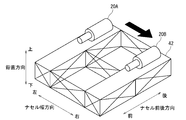
- FIG. 4 shows an example of an in-phase natural vibration mode.
- the rear portion of the gantry 42 swings to the left and right in the width direction of the nacelle 12 as indicated by arrows. Vibrate.
- the rotation direction of the rotation shaft 30 of the second hydraulic motor 20B is opposite to the rotation direction of the rotation shaft 30 of the first hydraulic motor 20A.
- the plurality of pistons 36 in the second hydraulic motor 20B which are mirror-symmetrically related to the plurality of pistons 36 in the first hydraulic motor 20A, are substantially the same as the reciprocating motion of the plurality of pistons 36 in the first hydraulic motor 20A.
- the phase of the reciprocating motion of the plurality of pistons 36 in the first hydraulic motor 20A and the second hydraulic motor 20B is set so as to reciprocate at the same phase.
- the first hydraulic motor 20A Even if the plurality of pistons 36 reciprocate in the first hydraulic motor 20A to cause the nacelle 12 to vibrate in the in-phase natural vibration mode as shown in FIG. 5, the first hydraulic motor 20A
- the vibration of the nacelle 12 can be accurately canceled and suppressed by the reciprocating motion of the piston 36 in the second hydraulic motor 20B having a mirror-symmetrical relationship with the piston 36.
- the reverse is also true, and the vibration of the nacelle 12 can be accurately canceled and suppressed by the reciprocating motion of the piston 36 in the first hydraulic motor 20A having a mirror-symmetrical relationship with the piston 36 of the second hydraulic motor 20B.
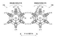
- a-1 to a-6 indicate the order in which the hydraulic oil is supplied to the working chamber 34 of the first hydraulic motor 20A
- b-1 to b-6 indicate the second hydraulic motor.
- the order in which the working oil is supplied to the working chamber 34 of 20B is shown.
- the numbers at the end are the same as a-1 and b-1, the working oil is supplied to the working chamber 34 at the same time.
- the first hydraulic motor 20A and the second hydraulic motor 20B have a conversion mechanism that converts a motion mode between the rotational motion of the rotary shaft 30 and the reciprocating motion of the piston 36.
- the first hydraulic motor 20A and the second hydraulic motor 20B are eccentrically attached to the rotary shaft 30 as a conversion mechanism, and have a disc-shaped eccentric cam 46 having a cam surface on the outer peripheral surface, and an eccentricity.
- a plurality of shoes 48 slidably in contact with the cam surface of the cam 46 and a plurality of joints 49 respectively connecting the plurality of shoes 48 and the plurality of pistons 36 are provided.
- the joint 49 is formed of, for example, a ball joint or a pin joint.
- the phase of the reciprocating motion of the piston 36 is defined by the rotation angle of the eccentric cam 46.
- the rotational direction of the eccentric cam 46 is set to the reverse direction.
- the absolute value of the rotation angle of the eccentric cam 46 may be matched. In order to match the rotation angle of the eccentric cam 46, for example, the start timings of the first hydraulic motor 20A and the second hydraulic motor 20B may be matched.
- a crank pin and a connecting rod that connects the piston and the crank pin are used as the conversion mechanism.
- a ring cam and a roller that connects the ring cam and the piston are used as the conversion mechanism.
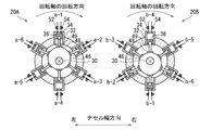
- the rotational direction of the rotary shaft 30 of the second hydraulic motor 20B is the same as the rotational direction of the rotary shaft 30 of the first hydraulic motor 20A.
- the first hydraulic motor 20A and the second hydraulic motor 20B are reciprocated with a phase difference of about 180 degrees with respect to the reciprocating motion of the plurality of pistons 36 in the first hydraulic motor 20A.
- the phase of the reciprocating motion of the plurality of pistons 36 in the second hydraulic motor 20B is set.
- the plurality of pistons 36 in the second hydraulic motor 20B reciprocate with a phase difference of 180 degrees with respect to the reciprocating movements of the plurality of pistons 36 in the first hydraulic motor 20A.
- the movement directions of the plurality of pistons 36 in the second hydraulic motor 20B which are in translational symmetry with the plurality of pistons 36 in the first hydraulic motor 20A, are different from the movement direction of the first piston 36. Therefore, even if the plurality of pistons 36 reciprocate in the first hydraulic motor 20A to cause the nacelle 12 to vibrate in the in-phase natural vibration mode as shown in FIG.
- the pistons of the first hydraulic motor 20A The vibration of the nacelle 12 can be accurately canceled and suppressed by the reciprocating motion of the piston 36 in the second hydraulic motor 20 ⁇ / b> B, which is in translational symmetry with respect to 36. The reverse is also true, and the vibration of the nacelle 12 can be accurately canceled and suppressed by the reciprocating motion of the piston 36 in the first hydraulic motor 20A that is in translational symmetry with the piston 36 of the second hydraulic motor 20B.
- phase difference of 180 degrees is given to the rotation angle of the eccentric cam 46.
- the start timing of the first hydraulic motor 20A and the second hydraulic motor 20B may be adjusted.
- FIG. 7 shows an example of the natural vibration mode of the reverse phase.
- the nacelle 12 vibrates in this natural vibration mode
- the rear left side and the rear right side of the gantry 42 are alternately turned up and down as indicated by arrows. Vibrate.
- the rotation direction of the rotation shaft 30 of the second hydraulic motor 20B is the same as the rotation direction of the rotation shaft 30 of the first hydraulic motor 20A.
- the first hydraulic motor 20A and the second hydraulic motor 20A are reciprocated in substantially the same phase with respect to the reciprocating motion of the plurality of pistons 36 in the first hydraulic motor 20A.
- the phase of the reciprocating motion of the plurality of pistons 36 in the hydraulic motor 20B is set.
- the piston 36 of the first hydraulic motor 20A is translationally symmetrical.
- the vibration of the nacelle 12 can be accurately canceled and suppressed by the reciprocating motion of the piston 36 in the second hydraulic motor 20B.
- the reverse is also true, and the vibration of the nacelle 12 can be accurately canceled and suppressed by the reciprocating motion of the piston 36 in the first hydraulic motor 20A that is in translational symmetry with the piston 36 of the second hydraulic motor 20B.
- the wind turbine generator further includes a control device 50 for controlling the first hydraulic motor 20A and the second hydraulic motor 20B, as shown in FIG.
- each of the two hydraulic motors 20 ⁇ / b> B includes a plurality of oil supply valves 52 for controlling supply of hydraulic oil to the plurality of working chambers 34, and discharge of hydraulic oil from the plurality of working chambers 34.
- a plurality of oil drain valves 54 for controlling each of the two.
- the control device 50 is constituted by a computer including, for example, a central processing unit (CPU), a memory, an external storage device, and an input / output device, and realizes a predetermined function by executing a program stored in the external storage device. Is possible.
- the control device 50 can be arranged in the nacelle 12 as illustrated in FIG. 1, or can be arranged in the tower 10.
- FIG. 9 schematically shows a configuration of a control system applied to the wind turbine generator.
- the control device 50 includes a phase control unit 56, and the phase control unit 56 sets the phase of the reciprocating motion of the plurality of pistons 36 in the first hydraulic motor 20 ⁇ / b> A and the second hydraulic motor 20 ⁇ / b> B. Set to the phase that was set.
- the phase control unit 56 controls at least a plurality of oil supply valves 52 among the plurality of oil supply valves 52 and the plurality of oil discharge valves 54 in the first hydraulic motor 20A and the second hydraulic motor 20B.
- the phase of the reciprocating motion of the piston 36 is adjusted to the set phase.
- control device 50 controls at least the oil supply valve 52 so that the phase of the reciprocating motion of the piston 36 in the first hydraulic motor 20A and the second hydraulic motor 20B matches the set phase, and the nacelle 12 Vibrations can be accurately canceled and suppressed.
- the wind turbine generator includes one or more vibration sensors 58 that can measure the vibration of the nacelle 12, as shown in FIG.
- the control device 50 includes a natural vibration mode determination unit 60 and a phase setting unit 62.
- the natural vibration mode determination unit 60 identifies the natural vibration mode of the nacelle 12 that is the cause of vibration, according to the measurement result of the vibration sensor 58.
- the phase setting unit 62 sets the phase of the piston 36 in the first hydraulic motor 20A and the second hydraulic motor 20B so as to suppress the vibration in the natural vibration mode according to the identified natural vibration mode ( Phase setting step).
- the phase control unit 56 controls at least the oil supply valve 52 of the oil supply valve 52 and the oil discharge valve 54 to adjust the phase of the reciprocating motion of the piston 36 to the phase set by the phase setting unit 62 (phase adjustment). Process).
- the setting of the phase to be matched can be changed as appropriate in accordance with the natural vibration mode that actually causes the vibration of the nacelle 12, and the vibration of the nacelle 12 can be accurately canceled and suppressed. it can.
- the control device 50 includes an operation state switching unit 64, and the operation state switching unit 64 includes a plurality of operations in the first hydraulic motor 20 ⁇ / b> A and the second hydraulic motor 20 ⁇ / b> B.
- the state of the plurality of working chambers 34 can be switched between an operating state and a non-operating state.
- the operation state switching unit 64 is configured to suppress the vibration of the nacelle 12 caused by the natural vibration mode of the nacelle 12 when switching the state of the at least one working chamber 34 in the first hydraulic motor 20A.
- the two hydraulic motors 20B are configured to switch the state of at least one working chamber 34.
- FIG. 10 shows an in-phase characteristic as shown in FIG. 4 when the first hydraulic motor 20A and the second hydraulic motor 20B are in the partial load operation state and the rotation direction of the rotary shaft 30 is the reverse direction.
- the phase of the piston 36 for suppressing the vibration in the vibration mode is shown.
- half of the working chambers 34 in the first hydraulic motor 20 ⁇ / b> A and the second hydraulic motor 20 ⁇ / b> B are set to the non-operating state, and every other working chamber 34 is set to the operating state in the circumferential direction of the rotating shaft 30.
- the working chamber 34 of the second hydraulic motor 20B in which the phase of the piston 36 is the same as that of the working chamber 34 set in the non-operating state in the first hydraulic motor 20A is set in the non-operating state.
- FIG. 11 shows an in-phase natural vibration as shown in FIG. 4 when the first hydraulic motor 20A and the second hydraulic motor 20B are in the partial load operation state and the rotation direction of the rotary shaft 30 is the same.
- the phase of the piston 36 for suppressing vibration in the mode is shown.
- half of the working chambers 34 in the first hydraulic motor 20 ⁇ / b> A and the second hydraulic motor 20 ⁇ / b> B are set to the non-operating state, and every other working chamber 34 is set to the operating state in the circumferential direction of the rotating shaft 30.
- the working chamber 34 of the second hydraulic motor 20B which is 180 degrees out of phase with the working chamber 34 set in the operating state in the first hydraulic motor 20A, is set in a non-operating state.
- FIG. 12 shows the characteristic of the reverse phase as shown in FIG. 7 when the first hydraulic motor 20A and the second hydraulic motor 20B are in the partial load operation state and the rotation direction of the rotary shaft 30 is the same.
- the phase of the piston 36 for suppressing the vibration in the vibration mode is shown.
- half of the working chambers 34 in the first hydraulic motor 20 ⁇ / b> A and the second hydraulic motor 20 ⁇ / b> B are set to the non-operating state, and every other working chamber 34 is set to the operating state in the circumferential direction of the rotating shaft 30.
- the working chamber 34 of the second hydraulic motor 20B whose phase of the piston 36 is the same as that of the working chamber 34 set in the non-operating state in the first hydraulic motor 20A, is set in the non-operating state.
- the state of the oil supply valve 52 is switched from the valve closed state to the valve open state, and the state of the oil discharge valve 54 is opened.
- the valve state is switched to the valve closed state.
- the state of the oil supply valve 52 is switched from the open state to the closed state, and the state of the oil discharge valve 54 is switched from the closed state to the open state. It is done.
- the oil supply valve 52 is always closed and the oil discharge valve 54 is always opened.
- the oil supply valve 52 and the oil discharge valve 54 are solenoid solenoid valves and are controlled to be opened and closed by the controller 50.
- a low-pressure oil refueling process in which low-pressure working oil is supplied to the working chamber through a refueling valve while the piston moves from top dead center to bottom dead center.
- an oil discharge step in which high-pressure hydraulic oil is discharged from the working chamber through the oil discharge valve while the piston is moving from the bottom dead center to the top dead center.
- the oil supply valve is opened while the oil discharge valve is closed.
- the oil discharge valve In the oil discharge process, the oil supply valve is closed and the oil discharge valve is opened.
- the oil supply valve is always opened and the oil discharge valve is always closed.
- the oil supply valve and the oil discharge valve of the hydraulic pump 18 are solenoid solenoid valves that are controlled to be opened and closed by the control device 50.
- the oil supply valve of the hydraulic pump 18 is a solenoid solenoid valve, while the oil discharge valve is a check valve, and only the oil supply valve is controlled to open and close by the controller 50.
- the non-operating working chamber 34 does not contribute to driving of the rotating shaft 30.
- the operating state of the first hydraulic motor 20A and the second hydraulic motor 20B when all the working chambers 34 are in the operating state is referred to as full load operation, and the first hydraulic pressure when some of the operating chambers 34 are in the non-operating state.
- the operating state of the motor 20A and the second hydraulic motor 20B is referred to as partial load operation.
- the non-operating working chamber does not contribute to the generation of high-pressure oil.
- the operating state of the hydraulic pump 18 when all the working chambers are in the operating state is referred to as full load operation, and the operating state of the hydraulic pump 18 when some of the operating chambers are in the inactive state is referred to as partial load operation.
- the wind turbine generator further includes a rotation speed sensor 66 capable of measuring the rotation speed of the main shaft 14 as illustrated in FIG. 9, and the control device 50 further includes a load determination unit 68. .
- the load determination unit 68 determines the number of operating chambers 34 (the number of operations) in the hydraulic pump 18, the first hydraulic motor 20A, and the second hydraulic motor 20B.
- the number of working chambers 34 in the activated state (the number of non-working chambers) is determined.
- the operation state switching unit 64 switches the state of the working chamber 34 so as to coincide with the number of operations or the number of non-operations determined by the load determination unit 68.
- the vibration of the nacelle 12 is suppressed while maintaining the optimum power generation efficiency, Operation noise can be suppressed.
- the number of actuations and the number of inactivations are in a complementary relationship, and determining the number of actuations is equivalent to determining the number of inactivations.
- the first hydraulic motor 20A and the second hydraulic motor 20B have a plurality of (m) pistons 36 arranged in the circumferential direction of the rotary shaft 30 as one group (piston group 70).
- a plurality (n rows) of piston groups 70 arranged in the axial direction of the rotary shaft 30 are provided.
- the first hydraulic motor 20 ⁇ / b> A and the second hydraulic motor 20 ⁇ / b> B each have six rows of piston groups 70 including six pistons 36.
- FIG. 13 the case of FIG.
- the phase of the reciprocating motion of the pistons 36 between the piston groups 70 differs by, for example, about 60 degrees corresponding to the number of the pistons 36 in the circumferential direction of the rotating shaft 30, and 6 ⁇ 6 pistons 36, six pistons 36 belonging to mutually different piston groups 70 and having different positions in the circumferential direction of the rotary shaft 30 reach the top dead center at the same time, and the other six pistons 70 belonging to mutually different piston groups 70 The piston 36 reaches the bottom dead center at the same time.
- the phase of the eccentric cam 46 is different for each piston group 70.
- the first hydraulic motor 20 ⁇ / b> A and the second hydraulic motor 20 ⁇ / b> B have a plurality of piston groups 70, and the reciprocating motion of the piston 36 so as to suppress the vibration of the nacelle 12 in the natural vibration mode. Is set.
- FIG. 14A shows the phases of the pistons 36 in the first to sixth rows of piston groups 70 in the first hydraulic motor 20A
- FIG. 14B shows the first to sixth rows of the second hydraulic motor 20B
- the phase of the piston 36 in the piston group 70 is shown.
- the phase of the piston 36 of the piston group 70 in the first row in the first hydraulic motor 20A and the first row in the second hydraulic motor 20B are set to be the same, and similarly, the phases of the pistons 36 are set to be the same between the corresponding rows.
- the vibration of the nacelle 12 in the natural vibration mode of the opposite phase as shown in FIG. 7 can be suppressed.
- the first hydraulic motor 20A and the second hydraulic motor 20B if the phase of the piston 36 and the rotation direction of the rotary shaft 30 in the corresponding row are set as shown in FIG. 5 or FIG.
- the vibration of the nacelle 12 in the in-phase natural vibration mode can be suppressed.
- the first hydraulic motor 20 ⁇ / b> A and the second hydraulic motor 20 ⁇ / b> B have a plurality of piston groups 70, and the reciprocating motion of the piston 36 so as to suppress the vibration of the nacelle 12 in the natural vibration mode. And the state of the working chamber 34 is switched between an activated state and a non-actuated state.
- FIG. 15A shows the phases of the pistons 36 in the first to sixth rows of piston groups 70 in the first hydraulic motor 20A
- FIG. 15B shows the first to sixth rows of the second hydraulic motor 20B
- the phase of the piston 36 in the piston group 70 is shown.
- the phase of the piston 36 of the piston group 70 in the first row in the first hydraulic motor 20A and the first row in the second hydraulic motor 20B are set to be the same, and similarly, the phases of the pistons 36 are set to be the same between the corresponding rows.
- each piston group 70 the three working chambers 34 are set to the operating state, the three working chambers 34 are set to the non-operating state, and the operating chamber 34 in the operating state and the non-operating working chamber 34 are rotated. They are arranged alternately in 30 circumferential directions.
- the second hydraulic motor 20B when the working chamber 34 formed by the piston 36 reciprocating at an arbitrary phase is set to the non-actuated state, the second hydraulic motor 20B has the same phase as that phase.
- the working chamber 34 formed by the piston 36 reciprocatingly is set in a non-actuated state.
- 15A and 15B since the rotation angle of the eccentric cam 46 is the same between the corresponding rows, when any one working chamber 34 of the first hydraulic motor 20A is set to the non-operating state, In the two hydraulic motors 20B, the working chambers 34 that belong to the same row as the working chambers 34 of the first hydraulic motor 20A set in the non-operating state and have a translational symmetric relationship are set in the non-operating state.
- the phase of the piston 36 in the corresponding row, the state of the working chamber 34, and the rotation direction of the rotary shaft 30 are set as shown in FIG. 10 or FIG.
- the vibration of the nacelle 12 in the in-phase natural vibration mode as shown in FIG. 4 can be suppressed.
- a rotation angle sensor 72 for measuring the rotation angle of the eccentric cam 46 in the first hydraulic motor 20A and the second hydraulic motor B may be further provided. Then, the control device 50 determines whether or not the actual phase of the piston 36 matches the set phase based on the measurement result of the rotation angle sensor 72, and adjusts the phase of the piston 36 according to the determination result. May be.
- a pitch adjusting mechanism 74 that adjusts the pitch angle of the blades 16 may be provided.
- the control device 50 may adjust the pitch angle of the blades 16 in accordance with the rotational speed of the main shaft 14.
- the tower 10 may be provided with a yaw adjustment mechanism 76 that adjusts the yaw angle of the nacelle 12.
- the control device 50 may adjust the yaw angle of the nacelle 12 according to the wind direction.
- the wind power generator may be installed on the ground or installed on the ocean.
- the present invention can also be applied to devices other than wind turbine generators and control methods thereof.
- the wind power generator is a device including a hydraulic system, and the nacelle 12 corresponds to a structure of the hydraulic system.
Landscapes
- Engineering & Computer Science (AREA)
- Mechanical Engineering (AREA)
- General Engineering & Computer Science (AREA)
- Chemical & Material Sciences (AREA)
- Combustion & Propulsion (AREA)
- Life Sciences & Earth Sciences (AREA)
- Sustainable Development (AREA)
- Sustainable Energy (AREA)
- Wind Motors (AREA)
Abstract
油圧システムは、構造体に搭載されたラジアルピストン式の第1の油圧機械と、前記構造体に搭載されたラジアルピストン式の第2の油圧機械と、を備え、前記第1の油圧機械及び第2の油圧機械の各々は、回転軸と、前記回転軸の少なくとも周方向に配列された複数のシリンダと、前記複数のシリンダとともに複数の作動室を形成する複数のピストンと、を有し、前記第1の油圧機械及び前記第2の油圧機械における前記複数のピストンの往復運動の位相は、前記構造体の振動を抑制するように設定される。
Description
本開示は、油圧システム、風力発電装置及びそれらの制御方法に関する。
地球環境の保全の観点から、再生可能エネルギーとしての風を利用して発電を行う風力発電装置の普及が進んでいる。風力発電装置は、一般的に、タワーによって支持されたナセルと、翼と、翼と共に回転可能にナセルによって支持されたメインシャフトとを有する。風力発電装置では、翼が受けた風力がメインシャフトの回転力に変換され、この回転力が、ナセルに設置された増速機構を介して発電機に入力され、電力に変換される。
近年、風力発電装置の大型化が進行しており、増速機構として、機械式の遊星歯車等に比べて軽量化が可能な油圧トランスミッションを用いた風力発電装置が開発されている。油圧トランスミッションは、油圧ポンプ及び油圧モータを組み合わせて構成されている。
例えば、特許文献1が開示する風力発電装置では、油圧ポンプ及び油圧モータは、ラジアルピストン式の油圧機械によって構成され、油圧機械では、複数のシリンダ及び複数のピストンが回転軸の周方向に配列されている。複数のシリンダ及び複数のピストンは、複数の作動室をそれぞれ形成しており、各作動室の容積は、各ピストンの往復運動を伴いながら増減する。ピストンの往復運動と回転軸の回転運動とは、運動モードの変換機構によって相互に変換可能である。そして、油圧機械には、複数の作動室への作動油の供給を制御するための複数の給油弁、及び、複数の作動室からの作動油の排出を制御するための排油弁が設けられている。
そして、特許文献2が開示する風力発電装置では、可変容量の油圧ポンプ及び油圧ポンプが用いられている。
具体的には、油圧ポンプの場合、給油弁(低圧弁)を開いたままにすることによって、作動室を作動油の圧縮に寄与しない非作動状態にすることができ、非作動状態の作動室の数を調整することによって、容量を調整することができる。
また、油圧モータの場合、給油弁(高圧弁)を閉じて排油弁(低圧弁)を開いたままの状態を維持することによって、作動室を、回転軸の駆動に寄与しない非作動状態にすることができ、非作動状態の作動室の数を調整することによって、容量を調整することができる。
具体的には、油圧ポンプの場合、給油弁(低圧弁)を開いたままにすることによって、作動室を作動油の圧縮に寄与しない非作動状態にすることができ、非作動状態の作動室の数を調整することによって、容量を調整することができる。
また、油圧モータの場合、給油弁(高圧弁)を閉じて排油弁(低圧弁)を開いたままの状態を維持することによって、作動室を、回転軸の駆動に寄与しない非作動状態にすることができ、非作動状態の作動室の数を調整することによって、容量を調整することができる。
一方、特許文献3は、ナセル内における油圧ポンプ及び油圧モータのレイアウト例を開示している。特許文献2の図2A及び2Bでは、油圧ポンプは、メインシャフトの同軸上に配置され、2つの油圧モータが、油圧ポンプの両側に配置されている。
風力発電装置の各部のうち、増速機構に用いられるラジアルピストン式の油圧機械は、相対的に大きな振動や動作音を発生する。そして、油圧機械の振動に起因して風力発電装置全体が振動すると、風力発電装置の動作音も大きくなる。
本発明の少なくとも一実施形態は、油圧機械の作動に起因する振動や動作音が抑制されて、静音性に優れた油圧システム、風力発電装置及びそれらの制御方法を提供することを目的とする。
本発明の少なくとも一実施形態に係る油圧システムは、
構造体に搭載されたラジアルピストン式の第1の油圧機械と、
前記構造体に搭載されたラジアルピストン式の第2の油圧機械と、を備え、
前記第1の油圧機械及び第2の油圧機械の各々は、
回転軸と、
前記回転軸の少なくとも周方向に配列された複数のシリンダと、
前記複数のシリンダとともに複数の作動室を形成する複数のピストンと、を有し、
前記第1の油圧機械及び前記第2の油圧機械における前記複数のピストンの往復運動の位相は、前記構造体の振動を抑制するように設定される。
構造体に搭載されたラジアルピストン式の第1の油圧機械と、
前記構造体に搭載されたラジアルピストン式の第2の油圧機械と、を備え、
前記第1の油圧機械及び第2の油圧機械の各々は、
回転軸と、
前記回転軸の少なくとも周方向に配列された複数のシリンダと、
前記複数のシリンダとともに複数の作動室を形成する複数のピストンと、を有し、
前記第1の油圧機械及び前記第2の油圧機械における前記複数のピストンの往復運動の位相は、前記構造体の振動を抑制するように設定される。
上記油圧システムでは、第1の油圧機械及び第2の油圧機械の各々が、ピストンの往復運動によって振動し、振動が構造体に加えられる。ただし、第1の油圧機械及び第2の油圧機械では、ピストンの往復運動の位相が、構造体の振動を抑制するように設定されるので、第1の油圧機械及び第2の油圧機械が振動したとしても、構造体の振動は抑制される。この結果、構造体の振動が抑制され、油圧システムの振動や動作音が抑制される。
幾つかの実施形態では、前記第1の油圧機械及び前記第2の油圧機械における前記複数のピストンの往復運動の位相は、前記構造体の固有振動モードに起因する前記構造体の振動を抑制するように設定される。
第1の油圧機械及び第2の油圧機械が設置される構造体には、その構造に応じて、固有の振動モードが存在する。そして、構造体に対し振動が加えられると、構造体が固有振動モードにて振動し、振動が油圧システム全体に伝搬する。
この点、上記油圧システムでも、第1の油圧機械及び第2の油圧機械の各々が、ピストンの往復運動によって振動し、振動が構造体に加えられる。ただし、第1の油圧機械及び第2の油圧機械では、ピストンの往復運動の位相が、構造体の固有振動モードに起因する構造体の振動を抑制するように設定されるので、第1の油圧機械及び第2の油圧機械が振動したとしても、固有振動モードでの構造体の振動は抑制される。この結果、構造体の振動が風力発電装置全体に伝搬することが抑制され、風力発電装置の振動や動作音が抑制される。
この点、上記油圧システムでも、第1の油圧機械及び第2の油圧機械の各々が、ピストンの往復運動によって振動し、振動が構造体に加えられる。ただし、第1の油圧機械及び第2の油圧機械では、ピストンの往復運動の位相が、構造体の固有振動モードに起因する構造体の振動を抑制するように設定されるので、第1の油圧機械及び第2の油圧機械が振動したとしても、固有振動モードでの構造体の振動は抑制される。この結果、構造体の振動が風力発電装置全体に伝搬することが抑制され、風力発電装置の振動や動作音が抑制される。
幾つかの実施形態では、前記第1の油圧機械及び前記第2の油圧機械は、仮想的なミラー面を中心として鏡映対称に配置されている。
この構成では、鏡映対称位置に配置したことにより、第1の油圧機械の振動によって引き起こされる構造体の振動を、第2の油圧機械の振動によって的確に打ち消して抑制することができる。逆も同様であり、第2の油圧機械の振動によって引き起こされる構造体の振動を、第1の油圧機械の振動によって的確に打ち消して抑制することができる。
幾つかの実施形態では、前記第1の油圧機械の回転軸の回転方向に対し、前記第2の油圧機械の回転軸の回転方向が逆方向になるように構成され、
前記第1の油圧機械における前記複数のピストンの往復運動に対し、前記第1の油圧機械における前記複数のピストンと鏡映対称の関係にある前記第2の油圧機械における前記複数のピストンが略同じ位相にて往復運動するように、前記第1の油圧機械及び前記第2の油圧機械における前記複数のピストンの往復運動の位相が設定される。
前記第1の油圧機械における前記複数のピストンの往復運動に対し、前記第1の油圧機械における前記複数のピストンと鏡映対称の関係にある前記第2の油圧機械における前記複数のピストンが略同じ位相にて往復運動するように、前記第1の油圧機械及び前記第2の油圧機械における前記複数のピストンの往復運動の位相が設定される。
構造体の固有振動モードには、第1の油圧機械及び第2の油圧機械の設置位置において振動方向が同一である同相の固有振動モードと、振動方向が逆向きである逆相の振動モードがある。
この構成では、第1の油圧機械において複数のピストンが往復運動することによって、同相の固有振動モードでの構造体の振動を引き起こしても、第1の油圧機械のピストンと鏡映対称の関係にある第2の油圧機械におけるピストンの往復運動によって構造体の振動を的確に打ち消して抑制することができる。逆も同様である。
この構成では、第1の油圧機械において複数のピストンが往復運動することによって、同相の固有振動モードでの構造体の振動を引き起こしても、第1の油圧機械のピストンと鏡映対称の関係にある第2の油圧機械におけるピストンの往復運動によって構造体の振動を的確に打ち消して抑制することができる。逆も同様である。
幾つかの実施形態では、前記第1の油圧機械の回転軸の回転方向に対し、前記第2の油圧機械の回転軸の回転方向が同じ方向になるように構成され、且つ、
前記第1の油圧機械における前記複数のピストンの往復運動に対し、前記第2の油圧機械における前記複数のピストンが略180度の位相差をもって往復運動するように、前記第1の油圧機械及び前記第2の油圧機械における前記複数のピストンの往復運動の位相が設定される。
前記第1の油圧機械における前記複数のピストンの往復運動に対し、前記第2の油圧機械における前記複数のピストンが略180度の位相差をもって往復運動するように、前記第1の油圧機械及び前記第2の油圧機械における前記複数のピストンの往復運動の位相が設定される。
この構成では、第1の油圧機械における複数のピストンの往復運動に対し、第2の油圧機械における複数のピストンが180度の位相差をもって往復運動することで、第1の油圧機械における複数のピストンの運動方向に対し、第2の油圧機械における複数のピストンの運動方向が逆向きになる。このため、第1の油圧機械において複数のピストンが往復運動することによって、逆相の固有振動モードでの構造体の振動を引き起こしても、第2の油圧機械におけるピストンの往復運動によって構造体の振動を的確に打ち消して抑制することができる。逆も同様である。
幾つかの実施形態では、前記第1の油圧機械の回転軸の回転方向に対し、前記第2の油圧機械の回転軸の回転方向が同じ方向になるように構成され、且つ、
前記第1の油圧機械における前記複数のピストンの往復運動に対し、前記第2の油圧機械における前記複数のピストンが略同じ位相にて往復運動するように、前記第1の油圧機械及び前記第2の油圧機械における前記複数のピストンの往復運動の位相が設定される。
前記第1の油圧機械における前記複数のピストンの往復運動に対し、前記第2の油圧機械における前記複数のピストンが略同じ位相にて往復運動するように、前記第1の油圧機械及び前記第2の油圧機械における前記複数のピストンの往復運動の位相が設定される。
この構成では、第1の油圧機械において複数のピストンが往復運動することによって、逆相の固有振動モードでの構造体の振動を引き起こしても、第2の油圧機械におけるピストンの往復運動によって構造体の振動を的確に打ち消して抑制することができる。逆も同様である。
幾つかの実施形態では、風力発電装置は、前記第1の油圧機械及び前記第2の油圧機械を制御するための制御装置を更に備え、
前記第1の油圧機械及び前記第2の油圧機械の各々は、
前記複数の作動室に対する作動油の供給をそれぞれ制御するための複数の給油弁と、
前記複数の作動室からの作動油の排出をそれぞれ制御するための複数の排油弁と、
を更に有し、
前記制御装置は、前記第1の油圧機械及び前記第2の油圧機械における前記複数の給油弁及び前記複数の排油弁のうち少なくとも前記複数の給油弁を制御することにより、前記第1の油圧機械及び前記第2の油圧機械における前記複数のピストンの往復運動の位相を設定された位相に合わせるように構成されている。
前記第1の油圧機械及び前記第2の油圧機械の各々は、
前記複数の作動室に対する作動油の供給をそれぞれ制御するための複数の給油弁と、
前記複数の作動室からの作動油の排出をそれぞれ制御するための複数の排油弁と、
を更に有し、
前記制御装置は、前記第1の油圧機械及び前記第2の油圧機械における前記複数の給油弁及び前記複数の排油弁のうち少なくとも前記複数の給油弁を制御することにより、前記第1の油圧機械及び前記第2の油圧機械における前記複数のピストンの往復運動の位相を設定された位相に合わせるように構成されている。
この構成によれば、制御装置が少なくとも給油弁を制御することにより、第1の油圧機械及び第2の油圧機械におけるピストンの往復運動の位相を設定された位相に合わせ、構造体の振動を的確に打ち消して抑制することができる。
特に、この構成によれば、構造体の振動を現実に引き起こしている固有振動モードに対応して、合わせるべき位相の設定を適宜変更することができ、構造体の振動を的確に打ち消して抑制することができる。
特に、この構成によれば、構造体の振動を現実に引き起こしている固有振動モードに対応して、合わせるべき位相の設定を適宜変更することができ、構造体の振動を的確に打ち消して抑制することができる。
幾つかの実施形態では、前記制御装置は、
前記第1の油圧機械及び前記第2の油圧機械における前記複数の給油弁及び前記複数の排油弁のうち少なくとも前記複数の給油弁を制御することにより、前記複数の作動室の状態を、作動状態と非作動状態との間で切り替え可能であり、且つ、
前記第1の油圧機械における少なくとも1つの前記作動室の状態の切り替えを行う場合に、前記構造体の振動を抑制するように、前記第2の油圧機械における少なくとも1つの前記作動室の状態の切り替えを行うように構成されている。
前記第1の油圧機械及び前記第2の油圧機械における前記複数の給油弁及び前記複数の排油弁のうち少なくとも前記複数の給油弁を制御することにより、前記複数の作動室の状態を、作動状態と非作動状態との間で切り替え可能であり、且つ、
前記第1の油圧機械における少なくとも1つの前記作動室の状態の切り替えを行う場合に、前記構造体の振動を抑制するように、前記第2の油圧機械における少なくとも1つの前記作動室の状態の切り替えを行うように構成されている。
この構成によれば、第1の油圧機械及び第2の油圧機械が、全ての作動室が作動状態である全負荷で作動している場合のみならず、一部の作動室が非作動状態である部分負荷で作動している場合でも、構造体の振動を的確に打ち消して抑制することができる。
幾つかの実施形態では、前記制御装置は、
前記第1の油圧機械における少なくとも1つの前記作動室の状態を非作動状態に切り替える場合に、前記第2の油圧機械における少なくとも1つの前記作動室であって、前記第1の油圧機械で非作動状態に切り替えられる前記作動室を形成する前記ピストンと同じ位相で往復運動する前記ピストンによって形成される前記作動室の状態を非作動状態に切り替えるように構成されている。
前記第1の油圧機械における少なくとも1つの前記作動室の状態を非作動状態に切り替える場合に、前記第2の油圧機械における少なくとも1つの前記作動室であって、前記第1の油圧機械で非作動状態に切り替えられる前記作動室を形成する前記ピストンと同じ位相で往復運動する前記ピストンによって形成される前記作動室の状態を非作動状態に切り替えるように構成されている。
この構成によれば、第1の油圧機械及び第2の油圧機械が部分負荷で作動しているときでも、構造体の振動を的確に抑制することができる。
幾つかの実施形態では、前記制御装置は、
前記第1の油圧機械における少なくとも1つの前記作動室の状態を非作動状態に切り替える場合に、前記第2の油圧機械における少なくとも1つの前記作動室であって、前記第1の油圧機械で非作動状態に切り替えられる前記作動室を形成する前記ピストンとは逆の位相で往復運動する前記ピストンによって形成される前記作動室の状態を非作動状態に切り替えるように構成されている。
前記第1の油圧機械における少なくとも1つの前記作動室の状態を非作動状態に切り替える場合に、前記第2の油圧機械における少なくとも1つの前記作動室であって、前記第1の油圧機械で非作動状態に切り替えられる前記作動室を形成する前記ピストンとは逆の位相で往復運動する前記ピストンによって形成される前記作動室の状態を非作動状態に切り替えるように構成されている。
この構成によれば、第1の油圧機械及び第2の油圧機械が部分負荷で作動しているときでも、構造体の振動を的確に抑制することができる。
本発明の少なくとも一実施形態に係る風力発電装置は、
タワーによって支持されたナセルと、
少なくとも一本の翼と、
前記翼と共に回転可能に前記ナセルによって支持されたメインシャフトと、
前記ナセル内に配置され、前記メインシャフトの回転によって駆動されるように構成された油圧ポンプと、
前記ナセル内に配置され、前記油圧ポンプで生成された圧油によって駆動されるように構成された油圧モータと、
前記油圧モータによって駆動されるように構成された発電機と、
を備える風力発電装置であって、
前記油圧ポンプ及び前記油圧モータの一方は、ラジアルピストン式の第1の油圧機械及び第2の油圧機械を含み、
前記第1の油圧機械及び第2の油圧機械の各々は、
回転軸と、
前記回転軸の少なくとも周方向に配列された複数のシリンダと、
前記複数のシリンダとともに複数の作動室を形成する複数のピストンと、を有する風力発電装置の制御方法において、
前記第1の油圧機械及び前記第2の油圧機械における前記複数のピストンの往復運動の位相は、前記ナセルの振動を抑制するように設定される。
タワーによって支持されたナセルと、
少なくとも一本の翼と、
前記翼と共に回転可能に前記ナセルによって支持されたメインシャフトと、
前記ナセル内に配置され、前記メインシャフトの回転によって駆動されるように構成された油圧ポンプと、
前記ナセル内に配置され、前記油圧ポンプで生成された圧油によって駆動されるように構成された油圧モータと、
前記油圧モータによって駆動されるように構成された発電機と、
を備える風力発電装置であって、
前記油圧ポンプ及び前記油圧モータの一方は、ラジアルピストン式の第1の油圧機械及び第2の油圧機械を含み、
前記第1の油圧機械及び第2の油圧機械の各々は、
回転軸と、
前記回転軸の少なくとも周方向に配列された複数のシリンダと、
前記複数のシリンダとともに複数の作動室を形成する複数のピストンと、を有する風力発電装置の制御方法において、
前記第1の油圧機械及び前記第2の油圧機械における前記複数のピストンの往復運動の位相は、前記ナセルの振動を抑制するように設定される。
上記風力発電装置では、第1の油圧機械及び第2の油圧機械の各々が、ピストンの往復運動によって振動し、振動がナセルに加えられる。ただし、第1の油圧機械及び第2の油圧機械では、ピストンの往復運動の位相が、ナセルの振動を抑制するように設定されるので、第1の油圧機械及び第2の油圧機械が振動したとしても、ナセルの振動は抑制される。この結果、ナセルの振動が風力発電装置全体に伝搬することが抑制され、風力発電装置の振動や動作音が抑制される。
第1の油圧機械及び第2の油圧機械が設置されるナセルには、その構造に応じて、固有の振動モードが存在する。そして、ナセルに対し振動が加えられると、ナセルが固有振動モードにて振動し、振動が風力発電装置全体に伝搬する。
この点、上記風力発電装置でも、第1の油圧機械及び第2の油圧機械の各々が、ピストンの往復運動によって振動し、振動がナセルに加えられる。ただし、第1の油圧機械及び第2の油圧機械では、ピストンの往復運動の位相が、ナセルの固有振動モードに起因するナセルの振動を抑制するように設定されるので、第1の油圧機械及び第2の油圧機械が振動したとしても、固有振動モードでのナセルの振動は抑制される。この結果、ナセルの振動が風力発電装置全体に伝搬することが抑制され、風力発電装置の振動や動作音が抑制される。
この点、上記風力発電装置でも、第1の油圧機械及び第2の油圧機械の各々が、ピストンの往復運動によって振動し、振動がナセルに加えられる。ただし、第1の油圧機械及び第2の油圧機械では、ピストンの往復運動の位相が、ナセルの固有振動モードに起因するナセルの振動を抑制するように設定されるので、第1の油圧機械及び第2の油圧機械が振動したとしても、固有振動モードでのナセルの振動は抑制される。この結果、ナセルの振動が風力発電装置全体に伝搬することが抑制され、風力発電装置の振動や動作音が抑制される。
幾つかの実施形態では、前記第1の油圧機械及び前記第2の油圧機械は前記油圧モータであり、
前記ナセル内において、前記第1の油圧機械及び前記第2の油圧機械は、前記メインシャフトの軸線と鉛直軸を含む仮想的なミラー面を中心として鏡映対称に配置されている。
前記ナセル内において、前記第1の油圧機械及び前記第2の油圧機械は、前記メインシャフトの軸線と鉛直軸を含む仮想的なミラー面を中心として鏡映対称に配置されている。
この構成では、鏡映対称位置に配置したことにより、第1の油圧機械の振動によって引き起こされるナセルの振動を、第2の油圧機械の振動によって的確に打ち消して抑制することができる。逆も同様であり、第2の油圧機械の振動によって引き起こされるナセルの振動を、第1の油圧機械の振動によって的確に打ち消して抑制することができる。
本発明の少なくとも一実施形態に係る油圧システムの制御方法は、
構造体に搭載されたラジアルピストン式の第1の油圧機械と、
前記構造体に搭載されたラジアルピストン式の第2の油圧機械と、を備え、
前記第1の油圧機械及び第2の油圧機械の各々は、
回転軸と、
前記回転軸の少なくとも周方向に配列された複数のシリンダと、
前記複数のシリンダとともに複数の作動室を形成する複数のピストンと、を有する油圧システムの制御方法において、
前記第1の油圧機械及び前記第2の油圧機械における前記複数のピストンの往復運動の位相を、前記構造体の振動を抑制するように設定する設定工程を備える。
構造体に搭載されたラジアルピストン式の第1の油圧機械と、
前記構造体に搭載されたラジアルピストン式の第2の油圧機械と、を備え、
前記第1の油圧機械及び第2の油圧機械の各々は、
回転軸と、
前記回転軸の少なくとも周方向に配列された複数のシリンダと、
前記複数のシリンダとともに複数の作動室を形成する複数のピストンと、を有する油圧システムの制御方法において、
前記第1の油圧機械及び前記第2の油圧機械における前記複数のピストンの往復運動の位相を、前記構造体の振動を抑制するように設定する設定工程を備える。
上記油圧システムの制御方法によれば、第1の油圧機械及び第2の油圧機械では、ピストンの往復運動の位相が、構造体の振動を抑制するように設定されるので、第1の油圧機械及び第2の油圧機械が振動したとしても、構造体の振動は抑制される。この結果、構造体の振動が油圧システム全体に伝搬することが抑制され、油圧システムの振動や動作音が抑制される。
本発明の少なくとも一実施形態に係る風力発電装置の制御方法は、
前記タワーによって支持されたナセルと、
少なくとも一本の翼と、
前記翼と共に回転可能に前記ナセルによって支持されたメインシャフトと、
前記ナセル内に配置され、前記メインシャフトの回転によって駆動されるように構成された油圧ポンプと、
前記ナセル内に配置され、前記油圧ポンプで生成された圧油によって駆動されるように構成された油圧モータと、
前記油圧モータによって駆動されるように構成された発電機と、
を備える風力発電装置の制御方法であって、
前記油圧ポンプ及び前記油圧モータの一方は、ラジアルピストン式の第1の油圧機械及び第2の油圧機械を含み、
前記第1の油圧機械及び第2の油圧機械の各々は、
回転軸と、
前記回転軸の少なくとも周方向に配列された複数のシリンダと、
前記複数のシリンダとともに複数の作動室を形成する複数のピストンと、を有する風力発電装置の制御方法において、
前記第1の油圧機械及び前記第2の油圧機械における前記複数のピストンの往復運動の位相を、前記ナセルの振動を抑制するように設定する設定工程を備える。
前記タワーによって支持されたナセルと、
少なくとも一本の翼と、
前記翼と共に回転可能に前記ナセルによって支持されたメインシャフトと、
前記ナセル内に配置され、前記メインシャフトの回転によって駆動されるように構成された油圧ポンプと、
前記ナセル内に配置され、前記油圧ポンプで生成された圧油によって駆動されるように構成された油圧モータと、
前記油圧モータによって駆動されるように構成された発電機と、
を備える風力発電装置の制御方法であって、
前記油圧ポンプ及び前記油圧モータの一方は、ラジアルピストン式の第1の油圧機械及び第2の油圧機械を含み、
前記第1の油圧機械及び第2の油圧機械の各々は、
回転軸と、
前記回転軸の少なくとも周方向に配列された複数のシリンダと、
前記複数のシリンダとともに複数の作動室を形成する複数のピストンと、を有する風力発電装置の制御方法において、
前記第1の油圧機械及び前記第2の油圧機械における前記複数のピストンの往復運動の位相を、前記ナセルの振動を抑制するように設定する設定工程を備える。
上記風力発電装置の制御方法によれば、第1の油圧機械及び第2の油圧機械では、ピストンの往復運動の位相が、ナセルの振動を抑制するように設定されるので、第1の油圧機械及び第2の油圧機械が振動したとしても、ナセルの振動は抑制される。この結果、ナセルの振動が風力発電装置全体に伝搬することが抑制され、風力発電装置の振動や動作音が抑制される。
本発明の少なくとも一実施形態によれば、油圧機械の作動に起因する振動や動作音が抑制されて、静音性に優れた油圧システム、風力発電装置及びそれらの制御方法が提供される。
以下、添付図面に従って本発明の実施形態について説明する。ただし、実施形態に記載されている構成部品の寸法、材質、形状、及び、その相対的配置等は、本発明の範囲をこれに限定する趣旨ではなく、単なる説明例にすぎない。
図1は、本発明の幾つかの実施形態に係る風力発電装置の構成を概略的に示す側面図であり、図2は、該風力発電装置の構成を概略的に示す上面図である。
図1及び図2に示すように、風力発電装置は、タワー10と、タワー10によって支持されるナセル12と、ナセル12によって回転可能に支持されたメインシャフト14と、メインシャフト14と共に回転可能な少なくとも一本の翼16と、ナセル12内に配置され、メインシャフト14の回転によって駆動されるように構成された油圧ポンプ18と、ナセル12内に配置され、油圧ポンプ18によって生成された圧油によって駆動されるように構成された油圧モータ20と、油圧モータ20によって駆動されるように構成された発電機22と、を備える。
図1及び図2に示すように、風力発電装置は、タワー10と、タワー10によって支持されるナセル12と、ナセル12によって回転可能に支持されたメインシャフト14と、メインシャフト14と共に回転可能な少なくとも一本の翼16と、ナセル12内に配置され、メインシャフト14の回転によって駆動されるように構成された油圧ポンプ18と、ナセル12内に配置され、油圧ポンプ18によって生成された圧油によって駆動されるように構成された油圧モータ20と、油圧モータ20によって駆動されるように構成された発電機22と、を備える。
油圧ポンプ18及び油圧モータ20の一方は、ラジアルピストン式の第1の油圧機械及び第2の油圧機械を含む。幾つかの実施形態では、油圧モータ20は、第1の油圧機械(第1油圧モータ20A)及び第2の油圧機械(第2油圧モータ20B)を含む。
図3は、第1油圧モータ20Aの構成を概略的に示す縦断面図である。なお、第1油圧モータ20Aと第2油圧モータ20Bの構成は同一であるため、図3は、第2油圧モータ20Bの構成も概略的に示している。
図3は、第1油圧モータ20Aの構成を概略的に示す縦断面図である。なお、第1油圧モータ20Aと第2油圧モータ20Bの構成は同一であるため、図3は、第2油圧モータ20Bの構成も概略的に示している。
図3に示したように、第1油圧モータ20A及び第2油圧モータ20Bの各々は、回転軸30と、回転軸30の周方向に配列された複数のシリンダ32と、複数のシリンダ32内にそれぞれ配置され、複数のシリンダ32とともに複数の作動室34を形成する複数のピストン36とを有する。
第1油圧モータ20A及び第2油圧モータ20Bにおける複数のピストン36の往復運動の位相は、ナセル12の振動を抑制するように設定されている。
第1油圧モータ20A及び第2油圧モータ20Bにおける複数のピストン36の往復運動の位相は、ナセル12の振動を抑制するように設定されている。
上記風力発電装置では、第1油圧モータ20A及び第2油圧モータ20Bの各々が、ピストン36の往復運動によって振動し、振動がナセル12に加えられる。ただし、第1油圧モータ20A及び第2油圧モータ20Bでは、ピストン36の往復運動の位相が、ナセル12の振動を抑制するように設定されるので、第1油圧モータ20A及び第2油圧モータ20Bが振動したとしても、ナセル12の振動は抑制される。この結果、ナセル12の振動が風力発電装置全体に伝搬することが抑制され、風力発電装置の振動や動作音が抑制される。
幾つかの実施形態では、第1油圧モータ20A及び第2油圧モータ20Bにおける複数のピストン36の往復運動の位相は、ナセル12の固有振動モードに起因するナセル12の振動を抑制するように設定されている。
第1油圧モータ20A及び第2油圧モータ20Bが設置されるナセル12には、その構造に応じて、固有の振動モードが存在する。そして、ナセル12に対し振動が加えられると、ナセル12が固有振動モードにて振動し、振動が風力発電装置全体に伝搬する。
この点、上記風力発電装置でも、第1油圧モータ20A及び第2油圧モータ20Bの各々が、ピストン36の往復運動によって振動し、振動がナセル12に加えられる。ただし、第1油圧モータ20A及び第2油圧モータ20Bでは、ピストン36の往復運動の位相が、ナセル12の固有振動モードに起因するナセル12の振動を抑制するように設定されるので、第1油圧モータ20A及び第2油圧モータ20Bが振動したとしても、固有振動モードでのナセル12の振動は抑制される。この結果、ナセル12の振動が風力発電装置全体に伝搬することが抑制され、風力発電装置の振動や動作音が抑制される。
この点、上記風力発電装置でも、第1油圧モータ20A及び第2油圧モータ20Bの各々が、ピストン36の往復運動によって振動し、振動がナセル12に加えられる。ただし、第1油圧モータ20A及び第2油圧モータ20Bでは、ピストン36の往復運動の位相が、ナセル12の固有振動モードに起因するナセル12の振動を抑制するように設定されるので、第1油圧モータ20A及び第2油圧モータ20Bが振動したとしても、固有振動モードでのナセル12の振動は抑制される。この結果、ナセル12の振動が風力発電装置全体に伝搬することが抑制され、風力発電装置の振動や動作音が抑制される。
幾つかの実施形態では、図2に示したように、ナセル12内において、第1油圧モータ20A及び第2油圧モータ20Bは、メインシャフト14の軸線と鉛直軸を含む仮想的なミラー面38を中心として鏡映対称に配置されている。
この構成では、第1油圧モータ20A及び第2油圧モータ20Bを鏡映対称位置に配置したことにより、第1油圧モータ20Aの振動によって引き起こされる固有振動モードでのナセル12の振動を、第2油圧モータ20Bの振動によって的確に打ち消して抑制することができる。逆も同様であり、第2油圧モータ20Bの振動によって引き起こされる固有振動モードでのナセル12の振動を、第1油圧モータ20Aの振動によって的確に打ち消して抑制することができる。
幾つかの実施形態では、図1及び図2に示したように、ナセル12は、タワー10によって支持される基台40と、基台40によって支持される架台42と、基台40及び架台42を覆うハウジング44とを有する。第1油圧モータ20A及び第2油圧モータ20Bは架台42に固定され、ハウジング44によって囲まれている。なお、メインシャフト14を回転可能に支持する主軸受45は、基台40によって支持されている。
ナセル12の固有振動モードには、第1油圧モータ20A及び第2油圧モータ20Bの設置位置において振動方向が同一である同相の固有振動モードと、振動方向が逆向きである逆相の振動モードがある。ナセル12の固有振動モードは、例えば有限要素解析法(FEM)によって、予め把握することができる。
図4は、同相の固有振動モードの一例を示しており、この固有振動モードでナセル12が振動した場合、矢印で示したように、架台42の後部がナセル12の幅方向に左右に揺れるように振動する。
図4は、同相の固有振動モードの一例を示しており、この固有振動モードでナセル12が振動した場合、矢印で示したように、架台42の後部がナセル12の幅方向に左右に揺れるように振動する。
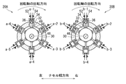
幾つかの実施形態では、図5に示したように、第1油圧モータ20Aの回転軸30の回転方向に対し、第2油圧モータ20Bの回転軸30の回転方向が逆方向になるように構成され、且つ、第1油圧モータ20Aにおける複数のピストン36の往復運動に対し、第1油圧モータ20Aにおける複数のピストン36と鏡映対称の関係にある第2油圧モータ20Bにおける複数のピストン36が略同じ位相にて往復運動するように、第1油圧モータ20A及び第2油圧モータ20Bにおける複数のピストン36の往復運動の位相が設定されている。
この構成では、第1油圧モータ20Aにおいて複数のピストン36が往復運動することによって、図5に示したような同相の固有振動モードでのナセル12の振動を引き起こしても、第1油圧モータ20Aのピストン36と鏡映対称の関係にある第2油圧モータ20Bにおけるピストン36の往復運動によってナセル12の振動を的確に打ち消して抑制することができる。逆も同様であり、第2油圧モータ20Bのピストン36と鏡映対称の関係にある第1油圧モータ20Aにおけるピストン36の往復運動によってナセル12の振動を的確に打ち消して抑制することができる。
なお、図5中、a-1~a-6は、第1油圧モータ20Aの作動室34に作動油が供給される順番を示しており、b-1~b-6は、第2油圧モータ20Bの作動室34に作動油が供給される順番を示しており、a-1とb-1のように末尾の数字が同じ場合、作動室34には作動油が同時に供給される。
第1油圧モータ20A及び第2油圧モータ20Bは、回転軸30の回転運動とピストン36の往復運動との間で運動モードの変換を行う変換機構を有する。幾つかの実施形態では、第1油圧モータ20A及び第2油圧モータ20Bは、変換機構として、回転軸30に対し偏心して取り付けられ、外周面にカム面を有する円盤形状の偏心カム46と、偏心カム46のカム面に摺接する複数のシュー48と、複数のシュー48と複数のピストン36とをそれぞれ連結する複数の継手49とを有する。継手49は、例えば球継手又はピン継手からなる。
この構成では、ピストン36の往復運動の位相は、偏心カム46の回転角によって規定される。第1油圧モータ20Aと第2油圧モータ20Bとの間で、鏡映対称の関係にあるピストン36の往復運動の位相を同じ位相に設定する場合、偏心カム46の回転方向を逆方向に設定し、偏心カム46の回転角の絶対値を一致させればよい。偏心カム46の回転角を一致させるには、例えば、第1油圧モータ20A及び第2油圧モータ20Bの起動のタイミングを一致させればよい。
幾つかの実施形態では、変換機構として、クランクピンと、ピストンとクランクピンとを連結する連接棒を用いられる。
また、幾つかの実施形態では、変換機構として、リングカムと、リングカムとピストンとを連結するローラが用いられる。
また、幾つかの実施形態では、変換機構として、リングカムと、リングカムとピストンとを連結するローラが用いられる。
幾つかの実施形態では、図6に示したように、第1油圧モータ20Aの回転軸30の回転方向に対し、第2油圧モータ20Bの回転軸30の回転方向が同じ方向になるように構成され、且つ、第1油圧モータ20Aにおける複数のピストン36の往復運動に対し、第2油圧モータ20Bにおける複数のピストン36が略180度の位相差をもって往復運動するように、第1油圧モータ20A及び第2油圧モータ20Bにおける複数のピストン36の往復運動の位相が設定される。
この構成では、第1油圧モータ20Aにおける複数のピストン36の往復運動に対し、第2油圧モータ20Bにおける複数のピストン36が180度の位相差をもって往復運動することで、第1油圧モータ20Aにおける複数のピストン36の運動方向に対し、第1油圧モータ20Aにおける複数のピストン36と並進対称の関係にある、第2油圧モータ20Bにおける複数のピストン36の運動方向が異なる向きになる。このため、第1油圧モータ20Aにおいて複数のピストン36が往復運動することによって、図4に示したような同相の固有振動モードでのナセル12の振動を引き起こしても、第1油圧モータ20Aのピストン36と並進対称の関係にある、第2油圧モータ20Bにおけるピストン36の往復運動によってナセル12の振動を的確に打ち消して抑制することができる。逆も同様であり、第2油圧モータ20Bのピストン36と並進対称の関係にある第1油圧モータ20Aにおけるピストン36の往復運動によってナセル12の振動を的確に打ち消して抑制することができる。
なお、第1油圧モータ20Aと第2油圧モータ20Bとの間で、ピストン36の往復運動に180度の位相差をもたせるには、偏心カム46の回転角に180度の位相差を付与すればよい。偏心カム46の回転角に180度の位相差を付与するには、例えば、第1油圧モータ20Aと第2油圧モータ20Bの起動のタイミングを調整すればよい。
図7は、逆相の固有振動モードの一例を示しており、この固有振動モードでナセル12が振動した場合、矢印で示したように、架台42の後部左側と後部右側が交互に上下方向に振動する。
幾つかの実施形態では、図8に示したように、第1油圧モータ20Aの回転軸30の回転方向に対し、第2油圧モータ20Bの回転軸30の回転方向が同じ方向になるように構成され、且つ、第1油圧モータ20Aにおける複数のピストン36の往復運動に対し、第2油圧モータ20Bにおける複数のピストン36が略同じ位相にて往復運動するように、第1油圧モータ20A及び第2油圧モータ20Bにおける複数のピストン36の往復運動の位相が設定される。
この構成では、第1油圧モータ20Aにおいて複数のピストン36が往復運動することによって、逆相の固有振動モードでのナセル12の振動を引き起こしても、第1油圧モータ20Aのピストン36と並進対称の関係にある、第2油圧モータ20Bにおけるピストン36の往復運動によってナセル12の振動を的確に打ち消して抑制することができる。逆も同様であり、第2油圧モータ20Bのピストン36と並進対称の関係にある第1油圧モータ20Aにおけるピストン36の往復運動によってナセル12の振動を的確に打ち消して抑制することができる。
幾つかの実施形態では、風力発電装置は、図1に示したように、第1油圧モータ20A及び第2油圧モータ20Bを制御するための制御装置50を更に備え、第1油圧モータ20A及び第2油圧モータ20Bの各々は、図3に示したように、複数の作動室34に対する作動油の供給をそれぞれ制御するための複数の給油弁52と、複数の作動室34からの作動油の排出をそれぞれ制御するための複数の排油弁54と、を更に有する。
制御装置50は、例えば、中央演算処理装置(CPU)、メモリ、外部記憶装置及び入出力装置からなるコンピュータによって構成され、外部記憶装置に記憶されたプログラムを実行することで、所定の機能を実現可能である。制御装置50は、図1に例示したようにナセル12内に配置することができ、或いは、タワー10内に配置することもできる。
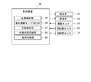
図9は、風力発電装置に適用される制御システムの構成を概略的に示している。図9に示したように、制御装置50は、位相制御部56を有し、位相制御部56は、第1油圧モータ20A及び第2油圧モータ20Bにおける複数のピストン36の往復運動の位相を設定された位相に合わせる。具体的には、位相制御部56は、第1油圧モータ20A及び第2油圧モータ20Bにおける複数の給油弁52及び複数の排油弁54のうち少なくとも複数の給油弁52を制御することにより、複数のピストン36の往復運動の位相を設定された位相に合わせる。
この構成によれば、制御装置50が少なくとも給油弁52を制御することにより、第1油圧モータ20A及び第2油圧モータ20Bにおけるピストン36の往復運動の位相を設定された位相に合わせ、ナセル12の振動を的確に打ち消して抑制することができる。
幾つかの実施形態では、図9に示したように、風力発電装置は、ナセル12の振動を測定可能な1つ以上の振動センサ58を有する。そして、制御装置50は、固有振動モード判定部60及び位相設定部62を有する。固有振動モード判定部60は、振動センサ58の測定結果に応じて、振動の原因となっているナセル12の固有振動モードを特定する。そして、位相設定部62は、特定された固有振動モードに応じて、固有振動モードでの振動を抑制するように、第1油圧モータ20A及び第2油圧モータ20Bにおけるピストン36の位相を設定する(位相設定工程)。そして、位相制御部56は、給油弁52及び排油弁54のうち少なくとも給油弁52を制御することによって、位相設定部62によって設定された位相にピストン36の往復運動の位相を合わせる(位相調整工程)。
この構成によれば、ナセル12の振動を現実に引き起こしている固有振動モードに対応して、合わせるべき位相の設定を適宜変更することができ、ナセル12の振動を的確に打ち消して抑制することができる。
幾つかの実施形態では、図9に示したように、制御装置50は、作動状態切替部64を有し、作動状態切替部64は、第1油圧モータ20A及び第2油圧モータ20Bにおける複数の給油弁52及び複数の排油弁54のうち少なくとも複数の給油弁52を制御することにより、複数の作動室34の状態を、作動状態と非作動状態との間で切り替え可能である。そして、作動状態切替部64は、第1油圧モータ20Aにおける少なくとも1つの作動室34の状態の切り替えを行う場合に、ナセル12の固有振動モードに起因するナセル12の振動を抑制するように、第2油圧モータ20Bにおける少なくとも1つの作動室34の状態の切り替えを行うように構成されている。
この構成によれば、第1油圧モータ20A及び第2油圧モータ20Bが、全ての作動室34が作動状態である全負荷で作動している場合のみならず、一部の作動室34が非作動状態である部分負荷で作動している場合でも、ナセル12の振動を的確に打ち消して抑制することができる。
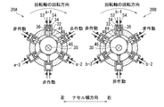
例えば、図10は、第1油圧モータ20A及び第2油圧モータ20Bが部分負荷運転状態であって、回転軸30の回転方向が逆方向であるときに、図4に示したような同相の固有振動モードでの振動を抑制するためのピストン36の位相を示している。
図10の場合、第1油圧モータ20A及び第2油圧モータ20Bにおいて半数の作動室34が非作動状態に設定され、回転軸30の周方向にて1つおきに作動室34が作動状態に設定されている。そして、第1油圧モータ20Aにおいて非作動状態に設定された作動室34に対しピストン36の位相が同じである第2油圧モータ20Bの作動室34が非作動状態に設定されている。
図10の場合、第1油圧モータ20A及び第2油圧モータ20Bにおいて半数の作動室34が非作動状態に設定され、回転軸30の周方向にて1つおきに作動室34が作動状態に設定されている。そして、第1油圧モータ20Aにおいて非作動状態に設定された作動室34に対しピストン36の位相が同じである第2油圧モータ20Bの作動室34が非作動状態に設定されている。
例えば、図11は、第1油圧モータ20A及び第2油圧モータ20Bが部分負荷運転状態であって、回転軸30の回転方向が同じであるときに、図4に示したような同相の固有振動モードでの振動を抑制するためのピストン36の位相を示している。
図11の場合、第1油圧モータ20A及び第2油圧モータ20Bにおいて半数の作動室34が非作動状態に設定され、回転軸30の周方向にて1つおきに作動室34が作動状態に設定されている。そして、第1油圧モータ20Aにおいて作動状態に設定された作動室34とはピストン36の位相が180度異なる第2油圧モータ20Bの作動室34が非作動状態に設定されている。
図11の場合、第1油圧モータ20A及び第2油圧モータ20Bにおいて半数の作動室34が非作動状態に設定され、回転軸30の周方向にて1つおきに作動室34が作動状態に設定されている。そして、第1油圧モータ20Aにおいて作動状態に設定された作動室34とはピストン36の位相が180度異なる第2油圧モータ20Bの作動室34が非作動状態に設定されている。
例えば、図12は、第1油圧モータ20A及び第2油圧モータ20Bが部分負荷運転状態であって、回転軸30の回転方向が同じであるときに、図7に示したような逆相の固有振動モードでの振動を抑制するためのピストン36の位相を示している。
図12の場合、第1油圧モータ20A及び第2油圧モータ20Bにおいて半数の作動室34が非作動状態に設定され、回転軸30の周方向にて1つおきに作動室34が作動状態に設定されている。そして、第1油圧モータ20Aにおいて非作動状態に設定された作動室34とはピストン36の位相が同じである第2油圧モータ20Bの作動室34が非作動状態に設定されている。
図12の場合、第1油圧モータ20A及び第2油圧モータ20Bにおいて半数の作動室34が非作動状態に設定され、回転軸30の周方向にて1つおきに作動室34が作動状態に設定されている。そして、第1油圧モータ20Aにおいて非作動状態に設定された作動室34とはピストン36の位相が同じである第2油圧モータ20Bの作動室34が非作動状態に設定されている。
以下、作動室34の作動状態及び非作動状態について説明する。
第1油圧モータ20A及び第2油圧モータ20Bでは、作動室34が作動状態である場合、ピストン36が上死点から下死点に向かう間に、給油弁52を通じて作動室34に高圧の作動油が供給される高圧油給油工程(行程)と、ピストン36が下死点から上死点に向かう間に、排油弁54を通じて作動室34から低圧の作動油が排出される排油工程(行程)とが繰り返される。給油工程では、給油弁52が開かれる一方、排油弁54が閉じられ、排油工程では、給油弁52が閉じられる一方、排油弁54が開かれる。
第1油圧モータ20A及び第2油圧モータ20Bでは、作動室34が作動状態である場合、ピストン36が上死点から下死点に向かう間に、給油弁52を通じて作動室34に高圧の作動油が供給される高圧油給油工程(行程)と、ピストン36が下死点から上死点に向かう間に、排油弁54を通じて作動室34から低圧の作動油が排出される排油工程(行程)とが繰り返される。給油工程では、給油弁52が開かれる一方、排油弁54が閉じられ、排油工程では、給油弁52が閉じられる一方、排油弁54が開かれる。
従って、作動室34が作動状態の場合、ピストン36が上死点近傍にあるときに、給油弁52の状態が閉弁状態から開弁状態へと切り替えられるとともに、排油弁54の状態が開弁状態から閉弁状態へと切り替えられる。そして、ピストン36が下死点近傍にあるときに、給油弁52の状態が開弁状態から閉弁状態へと切り替えられるとともに、排油弁54の状態が閉弁状態から開弁状態へと切り替えられる。
一方、第1油圧モータ20A及び第2油圧モータ20Bでは、作動室34が非作動状態である場合、ピストン36が上死点から下死点に向かう間に、排油弁54を通じて作動室34に低圧の作動油が供給される低圧油給油工程(行程)と、ピストン36が下死点から上死点に向かう間に、排油弁54を通じて作動室34から低圧の作動油が排出される排油工程(行程)とが繰り返される。
従って、作動室34が非作動状態の場合、給油弁52が常時閉じられ、排油弁54が常時開かれる。
幾つかの実施形態では、給油弁52及び排油弁54はソレノイド電磁弁であり、制御装置50によって開閉制御される。
幾つかの実施形態では、給油弁52及び排油弁54はソレノイド電磁弁であり、制御装置50によって開閉制御される。
一方、油圧ポンプ18では、作動室が作動状態である場合、ピストンが上死点から下死点に向かう間に、給油弁を通じて作動室に低圧の作動油が供給される低圧油給油工程(行程)と、ピストンが下死点から上死点に向かう間に、排油弁を通じて作動室から高圧の作動油が排出される排油工程(行程)とが繰り返される。給油工程では、給油弁が開かれる一方、排油弁が閉じられ、排油工程では、給油弁が閉じられる一方、排油弁が開かれる。
従って、作動室が作動状態の場合、ピストンが上死点近傍にあるときに、給油弁の状態が閉弁状態から開弁状態へと切り替えられるとともに、排油弁の状態が開弁状態から閉弁状態へと切り替えられる。そして、ピストンが下死点近傍にあるときに、給油弁の状態が開弁状態から閉弁状態へと切り替えられるとともに、排油弁の状態が閉弁状態から開弁状態へと切り替えられる。
一方、油圧ポンプ18では、作動室が非作動状態である場合、ピストンが上死点から下死点に向かう間に、給油弁を通じて作動室に低圧の作動油が供給される低圧油給油工程(行程)と、ピストンが下死点から上死点に向かう間に、給油弁を通じて作動室から低圧の作動油が排出される排油工程(行程)とが繰り返される。
従って、作動室が非作動状態の場合、給油弁が常時開かれ、排油弁が常時閉じられる。
幾つかの実施形態では、油圧ポンプ18の給油弁及び排油弁はソレノイド電磁弁であり、制御装置50によって開閉制御される。
また、幾つかの実施形態では、油圧ポンプ18の給油弁はソレノイド電磁弁である一方、排油弁は逆止弁であり、給油弁のみが制御装置50によって開閉制御される。
幾つかの実施形態では、油圧ポンプ18の給油弁及び排油弁はソレノイド電磁弁であり、制御装置50によって開閉制御される。
また、幾つかの実施形態では、油圧ポンプ18の給油弁はソレノイド電磁弁である一方、排油弁は逆止弁であり、給油弁のみが制御装置50によって開閉制御される。
上記したように、第1油圧モータ20A及び第2油圧モータ20Bにおいて、非作動状態の作動室34は、回転軸30の駆動に寄与しない。全ての作動室34が作動状態にあるときの第1油圧モータ20A及び第2油圧モータ20Bの運転状態を全負荷運転と称し、幾つかの作動室34が非作動状態にあるときの第1油圧モータ20A及び第2油圧モータ20Bの運転状態を部分負荷運転と称する。
同様に、油圧ポンプ18において、非作動状態の作動室は、高圧油の生成に寄与しない。全ての作動室が作動状態にあるときの油圧ポンプ18の運転状態を全負荷運転と称し、幾つかの作動室が非作動状態にあるときの油圧ポンプ18の運転状態を部分負荷運転と称する。
同様に、油圧ポンプ18において、非作動状態の作動室は、高圧油の生成に寄与しない。全ての作動室が作動状態にあるときの油圧ポンプ18の運転状態を全負荷運転と称し、幾つかの作動室が非作動状態にあるときの油圧ポンプ18の運転状態を部分負荷運転と称する。
幾つかの実施形態では、風力発電装置は、図9に示したように、メインシャフト14の回転数を測定可能な回転数センサ66を更に備え、制御装置50は、負荷判定部68を更に有する。負荷判定部68は、回転数センサ66の測定結果に応じて、油圧ポンプ18、第1油圧モータ20A及び第2油圧モータ20Bにおける、作動状態の作動室34の数(作動数)、或いは、非作動状態の作動室34の数(非作動数)を決定する。作動状態切替部64は、負荷判定部68によって決定された作動数又は非作動数に一致するように、作動室34の状態を切り替える。
この構成によれば、メインシャフト14の回転数に応じて作動数又は非作動数を決定することにより、最適の発電効率を維持しながら、ナセル12の振動を抑制し、風力発電装置の振動及び動作音を抑制することができる。
なお、作動数と非作動数は相補的な関係にあり、作動数を決定することは、非作動数を決定することに相当する。
なお、作動数と非作動数は相補的な関係にあり、作動数を決定することは、非作動数を決定することに相当する。
幾つかの実施形態では、第1油圧モータ20A及び第2油圧モータ20Bは、回転軸30の周方向に配列された複数(m個)のピストン36を1つの群(ピストン群70)としたときに、回転軸30の軸方向に配列された複数(n列)のピストン群70をそれぞれ備えている。
例えば、図13に示したように、第1油圧モータ20A及び第2油圧モータ20Bは、6個のピストン36からなるピストン群70を6列それぞれ有する。図13の場合では、ピストン群70間でピストン36の往復運動の位相が、回転軸30の周方向でのピストン36の数に対応して例えば約60度異なっており、6×6個のピストン36中、互いに異なるピストン群70に属し、回転軸30の周方向での位置が異なる6個のピストン36が上死点に同時に到達し、且つ、互いに異なるピストン群70に属する他の6個のピストン36が下死点に同時に到達する。
幾つかの実施形態では、ピストン群70毎に、偏心カム46の位相が異なっている。
例えば、図13に示したように、第1油圧モータ20A及び第2油圧モータ20Bは、6個のピストン36からなるピストン群70を6列それぞれ有する。図13の場合では、ピストン群70間でピストン36の往復運動の位相が、回転軸30の周方向でのピストン36の数に対応して例えば約60度異なっており、6×6個のピストン36中、互いに異なるピストン群70に属し、回転軸30の周方向での位置が異なる6個のピストン36が上死点に同時に到達し、且つ、互いに異なるピストン群70に属する他の6個のピストン36が下死点に同時に到達する。
幾つかの実施形態では、ピストン群70毎に、偏心カム46の位相が異なっている。
幾つかの実施形態では、第1油圧モータ20A及び第2油圧モータ20Bが複数のピストン群70を有しており、ナセル12の固有振動モードでの振動を抑制するように、ピストン36の往復運動の位相が設定される。
ここで、図14Aは、第1油圧モータ20Aにおける、1~6列目のピストン群70におけるピストン36の位相を示しており、図14Bは、第2油圧モータ20Bにおける、1~6列目のピストン群70におけるピストン36の位相を示している。
例えば、幾つかの実施形態では、図14A及び図14Bに示したように、第1油圧モータ20Aにおける1列目のピストン群70のピストン36の位相と、第2油圧モータ20Bにおける1列目のピストン群70のピストン36の位相が同じに設定され、以下同様に、対応する列間で、ピストン36の位相が同じになるように設定されている。
例えば、幾つかの実施形態では、図14A及び図14Bに示したように、第1油圧モータ20Aにおける1列目のピストン群70のピストン36の位相と、第2油圧モータ20Bにおける1列目のピストン群70のピストン36の位相が同じに設定され、以下同様に、対応する列間で、ピストン36の位相が同じになるように設定されている。
図14A及び図14Bに示したピストン36の位相によれば、図7に示したような逆相の固有振動モードでのナセル12の振動を抑制することができる。
なお、第1油圧モータ20A及び第2油圧モータ20Bにおいて、対応する列のピストン36の位相及び回転軸30の回転方向を、図5又は図6に示したように設定すれば、図4に示したような同相の固有振動モードでのナセル12の振動を抑制することができる。
なお、第1油圧モータ20A及び第2油圧モータ20Bにおいて、対応する列のピストン36の位相及び回転軸30の回転方向を、図5又は図6に示したように設定すれば、図4に示したような同相の固有振動モードでのナセル12の振動を抑制することができる。
幾つかの実施形態では、第1油圧モータ20A及び第2油圧モータ20Bが複数のピストン群70を有しており、ナセル12の固有振動モードでの振動を抑制するように、ピストン36の往復運動の位相が設定され、更に、作動室34の状態が、作動状態と非作動状態との間で切り替えられる。
ここで、図15Aは、第1油圧モータ20Aにおける、1~6列目のピストン群70におけるピストン36の位相を示しており、図15Bは、第2油圧モータ20Bにおける、1~6列目のピストン群70におけるピストン36の位相を示している。
例えば、幾つかの実施形態では、図15A及び図15Bに示したように、第1油圧モータ20Aにおける1列目のピストン群70のピストン36の位相と、第2油圧モータ20Bにおける1列目のピストン群70のピストン36の位相が同じに設定され、以下同様に、対応する列間で、ピストン36の位相が同じになるように設定されている。
そして、各ピストン群70において、3つの作動室34が作動状態に設定され、3つの作動室34が非作動状態に設定され、作動状態の作動室34と非作動状態の作動室34が回転軸30の周方向に交互に配列されている。
例えば、幾つかの実施形態では、図15A及び図15Bに示したように、第1油圧モータ20Aにおける1列目のピストン群70のピストン36の位相と、第2油圧モータ20Bにおける1列目のピストン群70のピストン36の位相が同じに設定され、以下同様に、対応する列間で、ピストン36の位相が同じになるように設定されている。
そして、各ピストン群70において、3つの作動室34が作動状態に設定され、3つの作動室34が非作動状態に設定され、作動状態の作動室34と非作動状態の作動室34が回転軸30の周方向に交互に配列されている。
そして更に、第1油圧モータ20Aにおいて、任意の一の位相で往復運動するピストン36によって形成される作動室34が非作動状態に設定されるとき、第2油圧モータ20Bにおいて、該位相と同じ位相で往復運動するピストン36によって形成される作動室34が非作動状態に設定されている。なお、図15A及び図15Bでは、対応する列間で偏心カム46の回転角が同一であるため、第1油圧モータ20Aの任意の一の作動室34が非作動状態に設定されるとき、第2油圧モータ20Bでは、非作動状態に設定された第1油圧モータ20Aの作動室34と同じ列に属し、並進対称関係にある作動室34が非作動状態に設定されている。
図15A及び図15Bに示したようなピストン36の位相によれば、図7に示したようなナセル12の逆相の固有振動モードでの振動を抑制するように、ピストン36の往復運動の位相が設定され、更に、作動室34の状態が、作動状態と非作動状態との間で切り替えられる。
なお、第1油圧モータ20A及び第2油圧モータ20Bにおいて、対応する列のピストン36の位相、作動室34の状態及び回転軸30の回転方向を、図10又は図11に示したように設定すれば、図4に示したような同相の固有振動モードでのナセル12の振動を抑制することができる。
幾つかの実施形態では、第1油圧モータ20A及び第2油圧モータBにおける偏心カム46の回転角を測定するための回転角センサ72を更に備えていてもよい。そして、制御装置50は、回転角センサ72の測定結果に基づいて、設定した位相にピストン36の現実の位相が合っているか否かを判定し、判定結果に応じて、ピストン36の位相を調整してもよい。
幾つかの実施形態では、第1油圧モータ20A及び第2油圧モータBにおける偏心カム46の回転角を測定するための回転角センサ72を更に備えていてもよい。そして、制御装置50は、回転角センサ72の測定結果に基づいて、設定した位相にピストン36の現実の位相が合っているか否かを判定し、判定結果に応じて、ピストン36の位相を調整してもよい。
以上、本発明の実施形態について詳細に説明したが、本発明はこれら実施形態に限定されず、実施形態を適宜組み合わせてもよく、本発明の要旨を逸脱しない範囲において、各種の改良や変形を行ってもよいのはいうまでもない。
例えば、風力発電装置では、翼16のピッチ角を調整するピッチ調整機構74が設けられていてもよい。そしてこの場合、制御装置50は、メインシャフト14の回転数に応じて、翼16のピッチ角を調整してもよい。また、タワー10には、ナセル12のヨー角を調整するヨー調整機構76が設けられていてもよい。そしてこの場合、制御装置50は、風向に応じて、ナセル12のヨー角を調整してもよい。また、風力発電装置は、地上に設置されるものであってもよく、洋上に設置されるものであってもよい。
例えば、風力発電装置では、翼16のピッチ角を調整するピッチ調整機構74が設けられていてもよい。そしてこの場合、制御装置50は、メインシャフト14の回転数に応じて、翼16のピッチ角を調整してもよい。また、タワー10には、ナセル12のヨー角を調整するヨー調整機構76が設けられていてもよい。そしてこの場合、制御装置50は、風向に応じて、ナセル12のヨー角を調整してもよい。また、風力発電装置は、地上に設置されるものであってもよく、洋上に設置されるものであってもよい。
また、本発明は、風力発電装置以外の装置やその制御方法にも適用可能であり、ラジアルピストン式の第1の油圧機械と、ラジアルピストン式の第2の油圧機械と、第1の油圧機械及び第2の油圧機械が搭載される構造体とを備える油圧システム及びその制御方法に適用可能である。風力発電装置は、油圧システムを備える装置であり、ナセル12が、油圧システムの構造体に相当する。
10 タワー
12 ナセル
14 メインシャフト
16 翼
18 油圧ポンプ
20 油圧モータ
20A 第1油圧モータ
20B 第2油圧モータ
22 発電機
30 回転軸
32 シリンダ
34 作動室
36 ピストン
38 ミラー面
40 基台
42 架台
44 ハウジング
45 主軸受
46 偏心カム
48 シュー
49 継手
50 制御装置
52 給油弁
54 排油弁
56 位相制御部
58 振動センサ
60 固有振動モード判定部
62 位相設定部
64 作動状態切替部
66 回転数センサ
68 負荷判定部
70 ピストン群
72 回転角センサ
74 ピッチ調整機構
76 ヨー調整機構
12 ナセル
14 メインシャフト
16 翼
18 油圧ポンプ
20 油圧モータ
20A 第1油圧モータ
20B 第2油圧モータ
22 発電機
30 回転軸
32 シリンダ
34 作動室
36 ピストン
38 ミラー面
40 基台
42 架台
44 ハウジング
45 主軸受
46 偏心カム
48 シュー
49 継手
50 制御装置
52 給油弁
54 排油弁
56 位相制御部
58 振動センサ
60 固有振動モード判定部
62 位相設定部
64 作動状態切替部
66 回転数センサ
68 負荷判定部
70 ピストン群
72 回転角センサ
74 ピッチ調整機構
76 ヨー調整機構
Claims (15)
- 構造体に搭載されたラジアルピストン式の第1の油圧機械と、
前記構造体に搭載されたラジアルピストン式の第2の油圧機械と、を備え、
前記第1の油圧機械及び第2の油圧機械の各々は、
回転軸と、
前記回転軸の少なくとも周方向に配列された複数のシリンダと、
前記複数のシリンダとともに複数の作動室を形成する複数のピストンと、を有し、
前記第1の油圧機械及び前記第2の油圧機械における前記複数のピストンの往復運動の位相は、前記構造体の振動を抑制するように設定される
ことを特徴とする油圧システム。 - 前記第1の油圧機械及び前記第2の油圧機械における前記複数のピストンの往復運動の位相は、前記構造体の固有振動モードに起因する前記構造体の振動を抑制するように設定されることを特徴とする請求項1に記載の油圧システム。
- 前記第1の油圧機械及び前記第2の油圧機械は、仮想的なミラー面を中心として鏡映対称に配置されていることを特徴とする請求項1又は2に記載の油圧システム。
- 前記第1の油圧機械の回転軸の回転方向に対し、前記第2の油圧機械の回転軸の回転方向が逆方向になるように構成され、
前記第1の油圧機械における前記複数のピストンの往復運動に対し、前記第1の油圧機械における前記複数のピストンと鏡映対称の関係にある前記第2の油圧機械における前記複数のピストンが略同じ位相にて往復運動するように、前記第1の油圧機械及び前記第2の油圧機械における前記複数のピストンの往復運動の位相が設定される
ことを特徴とする請求項1乃至3の何れか一項に記載の油圧システム。 - 前記第1の油圧機械の回転軸の回転方向に対し、前記第2の油圧機械の回転軸の回転方向が同じ方向になるように構成され、且つ、
前記第1の油圧機械における前記複数のピストンの往復運動に対し、前記第2の油圧機械における前記複数のピストンが略180度の位相差をもって往復運動するように、前記第1の油圧機械及び前記第2の油圧機械における前記複数のピストンの往復運動の位相が設定される
ことを特徴とする請求項1乃至3の何れか一項に記載の油圧システム。 - 前記第1の油圧機械の回転軸の回転方向に対し、前記第2の油圧機械の回転軸の回転方向が同じ方向になるように構成され、且つ、
前記第1の油圧機械における前記複数のピストンの往復運動に対し、前記第2の油圧機械における前記複数のピストンが略同じ位相にて往復運動するように、前記第1の油圧機械及び前記第2の油圧機械における前記複数のピストンの往復運動の位相が設定される
ことを特徴とする請求項1乃至3の何れか一項に記載の油圧システム。 - 前記第1の油圧機械及び前記第2の油圧機械を制御するための制御装置を更に備え、
前記第1の油圧機械及び前記第2の油圧機械の各々は、
前記複数の作動室に対する作動油の供給をそれぞれ制御するための複数の給油弁と、
前記複数の作動室からの作動油の排出をそれぞれ制御するための複数の排油弁と、
を更に有し、
前記制御装置は、前記第1の油圧機械及び前記第2の油圧機械における前記複数の給油弁及び前記複数の排油弁のうち少なくとも前記複数の給油弁を制御することにより、前記第1の油圧機械及び前記第2の油圧機械における前記複数のピストンの往復運動の位相を設定された位相に合わせるように構成されている
ことを特徴とする請求項1乃至6の何れか一項に記載の油圧システム。 - 前記制御装置は、
前記第1の油圧機械及び前記第2の油圧機械における前記複数の給油弁及び前記複数の排油弁のうち少なくとも前記複数の給油弁を制御することにより、前記複数の作動室の状態を、作動状態と非作動状態との間で切り替え可能であり、且つ、
前記第1の油圧機械における少なくとも1つの前記作動室の状態の切り替えを行う場合に、前記構造体の振動を抑制するように、前記第2の油圧機械における少なくとも1つの前記作動室の状態の切り替えを行うように構成されている
ことを特徴とする請求項7に記載の油圧システム。 - 前記制御装置は、
前記第1の油圧機械における少なくとも1つの前記作動室の状態を非作動状態に切り替える場合に、前記第2の油圧機械における少なくとも1つの前記作動室であって、前記第1の油圧機械で非作動状態に切り替えられる前記作動室を形成する前記ピストンと同じ位相で往復運動する前記ピストンによって形成される前記作動室の状態を非作動状態に切り替えるように構成されている
ことを特徴とする請求項8に記載の油圧システム。 - 前記制御装置は、
前記第1の油圧機械における少なくとも1つの前記作動室の状態を非作動状態に切り替える場合に、前記第2の油圧機械における少なくとも1つの前記作動室であって、前記第1の油圧機械で非作動状態に切り替えられる前記作動室を形成する前記ピストンとは逆の位相で往復運動する前記ピストンによって形成される前記作動室の状態を非作動状態に切り替えるように構成されている
ことを特徴とする請求項8に記載の油圧システム。 - タワーによって支持されたナセルと、
少なくとも一本の翼と、
前記翼と共に回転可能に前記ナセルによって支持されたメインシャフトと、
前記ナセル内に配置され、前記メインシャフトの回転によって駆動されるように構成された油圧ポンプと、
前記ナセル内に配置され、前記油圧ポンプで生成された圧油によって駆動されるように構成された油圧モータと、
前記油圧モータによって駆動されるように構成された発電機と、
を備える風力発電装置であって、
前記油圧ポンプ及び前記油圧モータの一方は、ラジアルピストン式の第1の油圧機械及び第2の油圧機械を含み、
前記第1の油圧機械及び第2の油圧機械の各々は、
回転軸と、
前記回転軸の少なくとも周方向に配列された複数のシリンダと、
前記複数のシリンダとともに複数の作動室を形成する複数のピストンと、を有し、
前記第1の油圧機械及び前記第2の油圧機械における前記複数のピストンの往復運動の位相は、前記ナセルの振動を抑制するように設定される
ことを特徴とする風力発電装置。 - 前記第1の油圧機械及び前記第2の油圧機械における前記複数のピストンの往復運動の位相は、前記ナセルの固有振動モードに起因する前記ナセルの振動を抑制するように設定されることを特徴とする請求項11に記載の風力発電装置。
- 前記第1の油圧機械及び前記第2の油圧機械は前記油圧モータであり、
前記ナセル内において、前記第1の油圧機械及び前記第2の油圧機械は、前記メインシャフトの軸線と鉛直軸を含む仮想的なミラー面を中心として鏡映対称に配置されている
ことを特徴とする請求項11又は12に記載の風力発電装置。 - 構造体に搭載されたラジアルピストン式の第1の油圧機械と、
前記構造体に搭載されたラジアルピストン式の第2の油圧機械と、を備え、
前記第1の油圧機械及び第2の油圧機械の各々は、
回転軸と、
前記回転軸の少なくとも周方向に配列された複数のシリンダと、
前記複数のシリンダとともに複数の作動室を形成する複数のピストンと、を有する油圧システムの制御方法において、
前記第1の油圧機械及び前記第2の油圧機械における前記複数のピストンの往復運動の位相を、前記構造体の振動を抑制するように設定する設定工程を備える
ことを特徴とする油圧システムの制御方法。 - タワーによって支持されたナセルと、
少なくとも一本の翼と、
前記翼と共に回転可能に前記ナセルによって支持されたメインシャフトと、
前記ナセル内に配置され、前記メインシャフトの回転によって駆動されるように構成された油圧ポンプと、
前記ナセル内に配置され、前記油圧ポンプで生成された圧油によって駆動されるように構成された油圧モータと、
前記油圧モータによって駆動されるように構成された発電機と、
を備える風力発電装置であって、
前記油圧ポンプ及び前記油圧モータの一方は、ラジアルピストン式の第1の油圧機械及び第2の油圧機械を含み、
前記第1の油圧機械及び第2の油圧機械の各々は、
回転軸と、
前記回転軸の少なくとも周方向に配列された複数のシリンダと、
前記複数のシリンダとともに複数の作動室を形成する複数のピストンと、を有する風力発電装置の制御方法において、
前記第1の油圧機械及び前記第2の油圧機械における前記複数のピストンの往復運動の位相を、前記ナセルの振動を抑制するように設定する設定工程を備える
ことを特徴とする風力発電装置の制御方法。
Priority Applications (1)
| Application Number | Priority Date | Filing Date | Title |
|---|---|---|---|
| PCT/JP2013/051996 WO2014118906A1 (ja) | 2013-01-30 | 2013-01-30 | 油圧システム、風力発電装置及びそれらの制御方法 |
Applications Claiming Priority (1)
| Application Number | Priority Date | Filing Date | Title |
|---|---|---|---|
| PCT/JP2013/051996 WO2014118906A1 (ja) | 2013-01-30 | 2013-01-30 | 油圧システム、風力発電装置及びそれらの制御方法 |
Publications (1)
| Publication Number | Publication Date |
|---|---|
| WO2014118906A1 true WO2014118906A1 (ja) | 2014-08-07 |
Family
ID=51261654
Family Applications (1)
| Application Number | Title | Priority Date | Filing Date |
|---|---|---|---|
| PCT/JP2013/051996 Ceased WO2014118906A1 (ja) | 2013-01-30 | 2013-01-30 | 油圧システム、風力発電装置及びそれらの制御方法 |
Country Status (1)
| Country | Link |
|---|---|
| WO (1) | WO2014118906A1 (ja) |
Cited By (5)
| Publication number | Priority date | Publication date | Assignee | Title |
|---|---|---|---|---|
| JP2016108942A (ja) * | 2014-12-02 | 2016-06-20 | 三菱重工業株式会社 | 油圧システム及び再生エネルギー型発電装置、並びにその運転方法 |
| CN110901935A (zh) * | 2019-11-27 | 2020-03-24 | 中国科学院西安光学精密机械研究所 | 一种用于大型航空光学吊舱的减振器及航空光学吊舱 |
| EP3674546A1 (en) * | 2018-12-28 | 2020-07-01 | Artemis Intelligent Power Limited | Valve timing in electronically commutated hydraulic machine |
| CN111594408A (zh) * | 2020-05-12 | 2020-08-28 | 合肥通用机械研究院有限公司 | 一种凸轮式往复压缩机构 |
| EP4663996A1 (de) * | 2024-06-10 | 2025-12-17 | Linde GmbH | Verfahren zur wasserstoffbetankung und wasserstoffbetankungsanlage |
Citations (5)
| Publication number | Priority date | Publication date | Assignee | Title |
|---|---|---|---|---|
| JPS58149435A (ja) * | 1982-03-01 | 1983-09-05 | Kyuzaburo Ikoma | 無振動ピストン機構 |
| US20070110590A1 (en) * | 2003-11-18 | 2007-05-17 | Carsten Pabst | Multipiston pump |
| JP2008309115A (ja) * | 2007-06-15 | 2008-12-25 | Sakushiyon Gas Kikan Seisakusho:Kk | 回転・往復動装置 |
| JP2012522175A (ja) * | 2010-02-23 | 2012-09-20 | アルテミス インテリジェント パワー リミティド | 可変容量型ラジアルピストン流体作動機械 |
| JP2012523515A (ja) * | 2010-02-23 | 2012-10-04 | アルテミス インテリジェント パワー リミティド | 流体作動機械および流体作動機械を動作させる方法 |
-
2013
- 2013-01-30 WO PCT/JP2013/051996 patent/WO2014118906A1/ja not_active Ceased
Patent Citations (5)
| Publication number | Priority date | Publication date | Assignee | Title |
|---|---|---|---|---|
| JPS58149435A (ja) * | 1982-03-01 | 1983-09-05 | Kyuzaburo Ikoma | 無振動ピストン機構 |
| US20070110590A1 (en) * | 2003-11-18 | 2007-05-17 | Carsten Pabst | Multipiston pump |
| JP2008309115A (ja) * | 2007-06-15 | 2008-12-25 | Sakushiyon Gas Kikan Seisakusho:Kk | 回転・往復動装置 |
| JP2012522175A (ja) * | 2010-02-23 | 2012-09-20 | アルテミス インテリジェント パワー リミティド | 可変容量型ラジアルピストン流体作動機械 |
| JP2012523515A (ja) * | 2010-02-23 | 2012-10-04 | アルテミス インテリジェント パワー リミティド | 流体作動機械および流体作動機械を動作させる方法 |
Cited By (10)
| Publication number | Priority date | Publication date | Assignee | Title |
|---|---|---|---|---|
| JP2016108942A (ja) * | 2014-12-02 | 2016-06-20 | 三菱重工業株式会社 | 油圧システム及び再生エネルギー型発電装置、並びにその運転方法 |
| EP3674546A1 (en) * | 2018-12-28 | 2020-07-01 | Artemis Intelligent Power Limited | Valve timing in electronically commutated hydraulic machine |
| JP2020109291A (ja) * | 2018-12-28 | 2020-07-16 | アルテミス インテリジェント パワー リミティドArtemis Intelligent Power Limited | 電子整流式油圧機械におけるバルブタイミング |
| US11649727B2 (en) | 2018-12-28 | 2023-05-16 | Artemis Intelligent Power Limited | Valve timing in electronically commutated hydraulic machine |
| JP7457499B2 (ja) | 2018-12-28 | 2024-03-28 | アルテミス インテリジェント パワー リミティド | 電子整流式油圧機械におけるバルブタイミング |
| CN110901935A (zh) * | 2019-11-27 | 2020-03-24 | 中国科学院西安光学精密机械研究所 | 一种用于大型航空光学吊舱的减振器及航空光学吊舱 |
| CN110901935B (zh) * | 2019-11-27 | 2021-03-19 | 中国科学院西安光学精密机械研究所 | 一种用于大型航空光学吊舱的减振器及航空光学吊舱 |
| CN111594408A (zh) * | 2020-05-12 | 2020-08-28 | 合肥通用机械研究院有限公司 | 一种凸轮式往复压缩机构 |
| EP4663996A1 (de) * | 2024-06-10 | 2025-12-17 | Linde GmbH | Verfahren zur wasserstoffbetankung und wasserstoffbetankungsanlage |
| WO2025256947A1 (de) * | 2024-06-10 | 2025-12-18 | Linde Gmbh | Verfahren zur wasserstoffbetankung und wasserstoffbetankungsanlage |
Similar Documents
| Publication | Publication Date | Title |
|---|---|---|
| JP5232873B2 (ja) | 風力発電装置及びその運転制御方法 | |
| WO2014118906A1 (ja) | 油圧システム、風力発電装置及びそれらの制御方法 | |
| JP5801822B2 (ja) | マルチローブリングカムを有する流体作動機械 | |
| CN103038506B (zh) | 流体工作机器以及运行流体工作机器的方法 | |
| JP5738477B2 (ja) | 発電装置及び発電装置のポンプ/モータの運転方法 | |
| ATE529620T1 (de) | Verbrennungsmotor mit variablem verdichtungsverhältnis | |
| WO2011028663A3 (en) | Rotary valve actuators having partial stroke damping apparatus | |
| JP6421099B2 (ja) | 油圧機械及びその運転方法、並びに再生エネルギー型発電装置 | |
| US20150354537A1 (en) | Radial Piston Pump and Wind Power Generator | |
| JP2013531185A (ja) | 力をピストンエンジンのピストンから伝達する装置 | |
| Wilhelm et al. | Synthesis of a variable displacement linkage for a hydraulic transformer | |
| JP2014181675A (ja) | 油圧機械および風力発電装置 | |
| CN105587481A (zh) | 一种高速变量轴向柱塞泵 | |
| CN105020117A (zh) | 一种群星对称无油压缩机 | |
| CN104265374A (zh) | 具有转轮传动活塞变速机构的流体动力机械 | |
| FI20085817A0 (fi) | Planeettaliikkeinen kiertomäntämoottori | |
| JP6560992B2 (ja) | ピストン装置及び油圧機械 | |
| JP2008545079A (ja) | 運動エネルギー発生装置 | |
| WO2008105208A1 (ja) | エンジン | |
| JP2005171857A (ja) | 4サイクル往復動式エンジン | |
| JP2009121540A (ja) | クランク装置 | |
| JP6165703B2 (ja) | 油圧システム及び再生エネルギー型発電装置、並びにその運転方法 | |
| JP4822184B2 (ja) | ストローク特性可変エンジン | |
| JP2016196847A (ja) | 可変容量型液圧ポンプとその制御方法 | |
| US20120272821A1 (en) | Thermal engine with an improved valve system |
Legal Events
| Date | Code | Title | Description |
|---|---|---|---|
| 121 | Ep: the epo has been informed by wipo that ep was designated in this application |
Ref document number: 13873420 Country of ref document: EP Kind code of ref document: A1 |
|
| NENP | Non-entry into the national phase |
Ref country code: DE |
|
| 122 | Ep: pct application non-entry in european phase |
Ref document number: 13873420 Country of ref document: EP Kind code of ref document: A1 |
|
| NENP | Non-entry into the national phase |
Ref country code: JP |