WO2014115824A1 - チタンまたはチタン合金からなる鋳塊の連続鋳造方法 - Google Patents
チタンまたはチタン合金からなる鋳塊の連続鋳造方法 Download PDFInfo
- Publication number
- WO2014115824A1 WO2014115824A1 PCT/JP2014/051426 JP2014051426W WO2014115824A1 WO 2014115824 A1 WO2014115824 A1 WO 2014115824A1 JP 2014051426 W JP2014051426 W JP 2014051426W WO 2014115824 A1 WO2014115824 A1 WO 2014115824A1
- Authority
- WO
- WIPO (PCT)
- Prior art keywords
- plasma torch
- temperature
- mold
- titanium
- output
- Prior art date
Links
Images


Classifications
-
- B—PERFORMING OPERATIONS; TRANSPORTING
- B22—CASTING; POWDER METALLURGY
- B22D—CASTING OF METALS; CASTING OF OTHER SUBSTANCES BY THE SAME PROCESSES OR DEVICES
- B22D11/00—Continuous casting of metals, i.e. casting in indefinite lengths
- B22D11/001—Continuous casting of metals, i.e. casting in indefinite lengths of specific alloys
-
- B—PERFORMING OPERATIONS; TRANSPORTING
- B22—CASTING; POWDER METALLURGY
- B22D—CASTING OF METALS; CASTING OF OTHER SUBSTANCES BY THE SAME PROCESSES OR DEVICES
- B22D11/00—Continuous casting of metals, i.e. casting in indefinite lengths
- B22D11/04—Continuous casting of metals, i.e. casting in indefinite lengths into open-ended moulds
- B22D11/041—Continuous casting of metals, i.e. casting in indefinite lengths into open-ended moulds for vertical casting
-
- B—PERFORMING OPERATIONS; TRANSPORTING
- B22—CASTING; POWDER METALLURGY
- B22D—CASTING OF METALS; CASTING OF OTHER SUBSTANCES BY THE SAME PROCESSES OR DEVICES
- B22D11/00—Continuous casting of metals, i.e. casting in indefinite lengths
- B22D11/10—Supplying or treating molten metal
- B22D11/103—Distributing the molten metal, e.g. using runners, floats, distributors
-
- B—PERFORMING OPERATIONS; TRANSPORTING
- B22—CASTING; POWDER METALLURGY
- B22D—CASTING OF METALS; CASTING OF OTHER SUBSTANCES BY THE SAME PROCESSES OR DEVICES
- B22D11/00—Continuous casting of metals, i.e. casting in indefinite lengths
- B22D11/10—Supplying or treating molten metal
- B22D11/11—Treating the molten metal
- B22D11/116—Refining the metal
- B22D11/117—Refining the metal by treating with gases
-
- B—PERFORMING OPERATIONS; TRANSPORTING
- B22—CASTING; POWDER METALLURGY
- B22D—CASTING OF METALS; CASTING OF OTHER SUBSTANCES BY THE SAME PROCESSES OR DEVICES
- B22D11/00—Continuous casting of metals, i.e. casting in indefinite lengths
- B22D11/16—Controlling or regulating processes or operations
-
- B—PERFORMING OPERATIONS; TRANSPORTING
- B22—CASTING; POWDER METALLURGY
- B22D—CASTING OF METALS; CASTING OF OTHER SUBSTANCES BY THE SAME PROCESSES OR DEVICES
- B22D21/00—Casting non-ferrous metals or metallic compounds so far as their metallurgical properties are of importance for the casting procedure; Selection of compositions therefor
- B22D21/002—Castings of light metals
- B22D21/005—Castings of light metals with high melting point, e.g. Be 1280 degrees C, Ti 1725 degrees C
-
- B—PERFORMING OPERATIONS; TRANSPORTING
- B22—CASTING; POWDER METALLURGY
- B22D—CASTING OF METALS; CASTING OF OTHER SUBSTANCES BY THE SAME PROCESSES OR DEVICES
- B22D27/00—Treating the metal in the mould while it is molten or ductile ; Pressure or vacuum casting
- B22D27/02—Use of electric or magnetic effects
-
- B—PERFORMING OPERATIONS; TRANSPORTING
- B22—CASTING; POWDER METALLURGY
- B22D—CASTING OF METALS; CASTING OF OTHER SUBSTANCES BY THE SAME PROCESSES OR DEVICES
- B22D27/00—Treating the metal in the mould while it is molten or ductile ; Pressure or vacuum casting
- B22D27/04—Influencing the temperature of the metal, e.g. by heating or cooling the mould
Definitions
- the present invention relates to a continuous casting method for an ingot made of titanium or a titanium alloy, in which an ingot made of titanium or a titanium alloy is continuously cast.
- An ingot is continuously cast by injecting a metal melted by vacuum arc melting or electron beam melting into a bottomless mold and drawing it downward while solidifying it.
- Patent Document 1 discloses an automatic control plasma melting casting method in which titanium or a titanium alloy is melted by plasma arc melting in an inert gas atmosphere and injected into a mold to be solidified.
- plasma arc melting performed in an inert gas atmosphere unlike electron beam melting performed in a vacuum, not only pure titanium but also a titanium alloy can be cast.
- the plasma torch is moved horizontally along a predetermined course in order to heat the entire surface of the molten metal. Then, the quality of the casting surface is improved over the entire ingot by optimizing the output, moving position, speed, and mold heat removal of the plasma torch on the molten metal surface.
- the operation operator has monitored the situation in the mold and manually performed operations such as switching the movement pattern of the plasma torch, but detection and response are delayed or overlooked. there is a possibility.
- An object of the present invention is to provide a continuous casting method of an ingot made of titanium or a titanium alloy capable of casting an ingot having a good casting surface state.
- a continuous casting method of an ingot made of titanium or a titanium alloy is obtained by injecting a molten metal in which titanium or a titanium alloy is melted into a bottomless mold and pulling it downward while solidifying the titanium or titanium alloy.
- a continuous casting method for continuously casting an ingot comprising: a plasma arc from the plasma torch while the plasma torch is horizontally moved on the molten metal surface in the mold.
- the amount of heat input per unit area from the plasma torch to the molten metal surface is controlled based on the temperature of the mold measured by the temperature sensor and the target temperature preset for each temperature sensor.
- the heat input / extraction state near the molten metal surface can be controlled appropriately. Thereby, the ingot with a favorable state of a casting surface can be cast.
- the heat input control step when the temperature of the mold measured by any one of the temperature sensors is lower than the target temperature, When the plasma torch approaches the location where the temperature sensor is installed, the output of the plasma torch is increased, and when the temperature of the mold measured by any of the temperature sensors is higher than the target temperature, the temperature The output of the plasma torch may be reduced when the plasma torch approaches a sensor installation location. According to the above configuration, by changing the output of the plasma torch in real time based on the temperature measurement value and the target temperature of the temperature sensor, it is possible to appropriately control the heat input / extraction state in the vicinity of the molten metal surface. .
- the plasma torch output correction amount is added to a reference plasma torch output pattern which is a standard output pattern of the plasma torch, thereby correcting the output of the plasma torch. Good.
- the output of the plasma torch can be changed in real time based on the temperature measurement value of the temperature sensor and the target temperature.
- the heat input per unit area from the plasma torch to the molten metal surface is changed in real time based on the temperature measurement value of the temperature sensor and the target temperature.
- the heat input / extraction state in the vicinity of the molten metal surface can be appropriately controlled.
- the ingot with a favorable state of a casting surface can be cast.
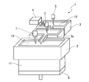
- FIG. 1 is a perspective view showing a continuous casting apparatus.
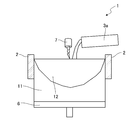
- FIG. 2 is a cross-sectional view showing a continuous casting apparatus.
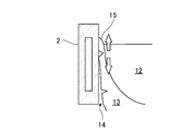
- FIG. 3A is an explanatory diagram showing a generation mechanism of surface defects.
- FIG. 3B is an explanatory diagram illustrating a generation mechanism of surface defects.
- FIG. 4 is a model view of the mold as viewed from the measuring method.
- FIG. 5 is a model view of the mold as seen from above.
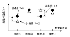
- FIG. 6A is a graph showing a method for calculating the corrected plasma torch output, and shows the actually measured temperature and the target temperature.
- FIG. 6B is a graph showing a method for calculating the corrected plasma torch output and shows a reference plasma torch output pattern.
- FIG. 1 is a perspective view showing a continuous casting apparatus.
- FIG. 2 is a cross-sectional view showing a continuous casting apparatus.
- FIG. 3A is an explanatory diagram showing a generation mechanism of surface defects.
- FIG. 3B is an explanatory diagram
- FIG. 6C is a graph showing a method for calculating the corrected plasma torch output, and shows the plasma torch output correction amount.
- FIG. 6D is a graph showing the plasma torch output calculation method after correction, and shows the plasma torch output.
- FIG. 7A is a graph showing a method for calculating the plasma torch output correction amount, and shows the plasma torch output correction value.
- FIG. 7B is a graph showing a method for calculating the plasma torch output correction amount, and shows correction coefficients.
- FIG. 7C is a graph showing a method for calculating the plasma torch output correction amount, and shows the plasma torch output correction amount.
- FIG. 8 is a perspective view showing a continuous casting apparatus different from FIG.
- an ingot continuous casting apparatus 1 made of titanium or a titanium alloy for performing this continuous casting method includes a mold 2, a cold hearth 3, , A raw material charging device 4, a plasma torch 5, a starting block 6, and a plasma torch 7.
- the continuous casting apparatus 1 is surrounded by an inert gas atmosphere made of argon gas, helium gas, or the like.
- the raw material input device 4 inputs the raw material of titanium or titanium alloy such as sponge titanium and scrap into the cold hearth 3.
- the plasma torch 5 is provided above the cold hearth 3 and generates a plasma arc to melt the raw material in the cold hearth 3.
- the cold hearth 3 injects the molten metal 12 in which the raw material is melted into the mold 2 from the pouring part 3a.
- the casting mold 2 is made of copper, has a bottom and has a rectangular cross-sectional shape, and is cooled by water circulating through at least a part of the rectangular tube-shaped wall portion.
- the starting block 6 can be moved up and down by a drive unit (not shown) to close the lower opening of the mold 2.
- the plasma torch 7 is provided above the molten metal 12 in the mold 2.
- the plasma torch 7 plasmas the molten metal 12 injected into the mold 2 while being horizontally moved on the molten metal 12 by moving means (not shown). Heat with an arc.
- the molten metal 12 injected into the mold 2 solidifies from the contact surface with the water-cooled mold 2. Then, by pulling down the starting block 6 that has closed the lower opening of the mold 2 at a predetermined speed, a prismatic ingot (slab) 11 in which the molten metal 12 has solidified is drawn downward. While continuously cast.
- the continuous casting apparatus 1 may have a flux feeding apparatus that feeds a solid phase or liquid phase flux to the molten metal surface of the molten metal 12 in the mold 2.
- a flux feeding apparatus that feeds a solid phase or liquid phase flux to the molten metal surface of the molten metal 12 in the mold 2.
- plasma arc melting in an inert gas atmosphere has the advantage that the flux can be charged into the molten metal 12 in the mold 2.
- a “tearing defect” occurs in which the surface of the shell 13 is torn off.
- the molten metal 12 is covered on the grown (thickened) solidified shell 13 to generate a “hot water covering defect”. Therefore, it is estimated that the heat input / extraction state to the initial solidification portion 15 in the vicinity of the molten metal surface of the molten metal 12 has a great influence on the properties of the casting surface, and the heat input / exhaust state in the vicinity of the molten metal surface of the molten metal 12 is appropriately controlled. It is considered that an ingot 11 having a good casting surface can be obtained.
- FIG. 4 which is a model view of the mold 2 as viewed from the measuring method
- FIG. 5 which is a model view of the mold 2 as viewed from above
- a plurality of locations of the mold 2 along the circumferential direction of the mold 2 Is provided with a thermocouple (temperature sensor) 21.
- thermocouple 21 temperature sensor
- the plasma torch 7 horizontally moved on the surface of the molten metal 12 based on the temperature of the mold 2 measured by each thermocouple 21 and the target temperature preset for each thermocouple 21.
- the output is controlled.
- the output of the plasma torch 7 is kept constant, the distance between the plasma torch 7 and the molten metal 12 is changed, or the flow rate of the plasma gas is changed to change the flow rate of the plasma torch 7 to the molten metal 12.
- the amount of heat input per unit area may be controlled.
- the means for measuring the temperature of the mold 2 is not limited to the thermocouple 21 and may be an optical fiber or the like.
- the temperature of the mold 2 measured by each thermocouple 21 is input to the control device 22.
- a target temperature value and a plasma torch output correction amount set in advance for each thermocouple 21 are input to the control device 22.
- the control device 22 outputs a plasma torch output control signal based on the temperature of the mold 2 and the target temperature measured by each thermocouple 21 to the plasma torch 7.
- the control device 22 causes the plasma when the plasma torch 7 approaches the place where the thermocouple 21 is installed.
- the output of the plasma torch 7 is controlled so as to increase the output of the torch 7.
- the control device 22 detects the plasma torch 7 when the plasma torch 7 approaches the place where the thermocouple 21 is installed.
- the output of the plasma torch 7 is controlled so as to reduce the output.
- the amount of heat input per unit area from the plasma torch 7 to the molten metal surface of the molten metal 12 is changed in real time based on the measured temperature value and the target temperature of the thermocouple 21, so that the vicinity of the molten metal surface of the molten metal 12.
- the heat input / extraction state can be appropriately controlled. Thereby, the ingot 11 with a favorable state of a casting surface can be cast.
- the heat input / extraction state near the molten metal surface of the molten metal 12 can be appropriately controlled.
- a reference plasma torch output pattern PA (L) [W], which is a reference output pattern of the plasma torch 7 capable of casting the ingot 11 having a good casting surface state. Determine in advance.
- PA (L) is an output value of the plasma torch 7 at a position L [m] in the moving path of the plasma torch 7.
- the target temperature Ta (i) [° C.] of the mold 2 at each side temperature position i is determined in advance by past operation results, simulations, or the like. Specifically, when casting using the reference plasma torch output pattern PA (L), the temperature at which the surface quality is measured or the temperature at which the surface quality is predicted to be good. Is used as the target temperature Ta (i).
- the target temperature Ta (i) may be an actually measured value or a calculated value by simulation. Further, based on ⁇ T (i), which is the difference between the actual temperature Tm (i) [° C.] measured by the thermocouple 21 and the target temperature Ta (i) of the mold 2, the plasma torch output correction amount ⁇ P (L, ⁇ T (i )) Obtain [W] in advance.
- ⁇ T (i) Tm (i) ⁇ Ta (i).
- thermocouples 21 are provided at each of the center of the long side of the mold 2 and the center of the short side of the mold 2.
- positions of these thermocouples 21 are defined as positions (1) to (4), respectively.
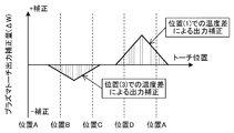
- FIG. 6A shows the measured temperature Tm (i) and the target temperature Ta (i) of the thermocouples 21 installed at the positions (1) to (4), respectively.
- FIG. 6B shows the reference plasma torch output pattern PA (L) at the torch positions A to D.
- the plasma torch output correction amount ⁇ P (L, ⁇ T (i)) is obtained from the difference ⁇ T (i) between the measured temperature Tm (i) and the target temperature Ta (i).
- FIG. 6C shows the plasma torch output correction amount ⁇ P (L, ⁇ T (i)) at the torch positions A to D.
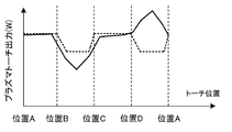
- the corrected plasma torch output P (L) is obtained by adding the plasma torch output correction amount ⁇ P (L, ⁇ T (i)) to the reference plasma torch output pattern PA (L).
- FIG. 6D shows the corrected plasma torch output P (L) at the torch positions AD.
- the output of the plasma torch 7 is corrected by adding the plasma torch output correction amount ⁇ P (L, ⁇ T (i)) to the reference plasma torch output pattern PA (L).
- the output of the plasma torch 7 can be changed in real time based on the temperature measurement value of the thermocouple 21 and the target temperature.
- the plasma torch output correction amount ⁇ P (L, ⁇ T (i)) is obtained by the following equation 2.
- N is the number of temperature measurement points
- ⁇ Pu (L, i) [W / ° C.] is the plasma torch output correction value when the measured temperature in the i-th thermocouple 21 deviates from the target temperature by unit temperature
- fd ( [Delta] T) [[deg.] C./[deg.] C.] is a correction coefficient based on the amount of deviation from the temperature measurement value.
- FIG. 7A shows the plasma torch output correction value ⁇ Pu (L, i).
- FIG. 7B shows the correction coefficient fd ( ⁇ T).
- FIG. 7C shows the plasma torch output correction value ⁇ P (L, ⁇ T (i)) obtained by the plasma torch output correction value ⁇ Pu (L, i) and the correction coefficient fd (Tm (i) ⁇ Ta (i)). Show.
- thermocouple 21 As described above, according to the continuous casting method of the ingot 11 made of titanium or titanium alloy according to this embodiment, the temperature of the mold 2 measured by the thermocouple 21 and the target set in advance for each thermocouple 21. Based on the temperature, the amount of heat input per unit area from the plasma torch 7 to the surface of the molten metal 12 is controlled. For example, the amount of heat input per unit area from the plasma torch 7 to the molten metal surface of the molten metal 12 is increased or decreased so that the temperature measurement value of the thermocouple 21 becomes the target temperature.
- the amount of heat input per unit area from the plasma torch 7 to the molten metal surface of the molten metal 12 is changed in real time based on the measured temperature value and the target temperature of the thermocouple 21, so that the vicinity of the molten metal surface of the molten metal 12.
- the heat input / extraction state can be appropriately controlled. Thereby, the ingot 11 with a favorable state of a casting surface can be cast.
- the output of the plasma torch 7 is increased when the plasma torch 7 approaches the place where the thermocouple 21 is installed.
- the output of the plasma torch 7 is reduced when the plasma torch 7 approaches the place where the thermocouple 21 is installed. In this way, by changing the output of the plasma torch 7 in real time based on the temperature measurement value of the thermocouple 21, the heat input / extraction state in the vicinity of the molten metal surface of the molten metal 12 can be appropriately controlled.
- the output of the plasma torch 7 is corrected by adding the plasma torch output correction amount to the reference plasma torch output pattern. Thereby, based on the temperature measurement value of the thermocouple 21, the output of the plasma torch 7 can be changed in real time.
- the continuous casting apparatus 201 which implements the continuous casting method of this embodiment may continuously cast the cylindrical ingot 211 using the mold 202 having a circular cross section, as shown in FIG.
Abstract
Description
本実施形態によるチタンまたはチタン合金からなる鋳塊の連続鋳造方法では、プラズマアーク溶解させたチタンまたはチタン合金の溶湯を無底の鋳型内に注入して凝固させながら下方に引抜くことで、チタンまたはチタン合金からなる鋳塊を連続的に鋳造する。この連続鋳造方法を実施するチタンまたはチタン合金からなる鋳塊の連続鋳造装置1は、斜視図である図1、および、断面図である図2に示すように、鋳型2と、コールドハース3と、原料投入装置4と、プラズマトーチ5と、スターティングブロック6と、プラズマトーチ7と、を有している。連続鋳造装置1のまわりは、アルゴンガスやヘリウムガス等からなる不活性ガス雰囲気にされている。
ところで、チタンまたはチタン合金からなる鋳塊11を連続鋳造した際に、鋳塊11の表面(鋳肌)に凹凸や傷があると、次工程である圧延過程で表面欠陥となる。このような鋳塊11表面の凹凸や傷は、圧延する前に切削等で取り除く必要があり、歩留まりの低下や作業工程の増加などに起因してコストアップの要因となる。そのため、表面に凹凸や傷が無い鋳塊11を鋳造することが求められる。
以上に述べたように、本実施形態に係るチタンまたはチタン合金からなる鋳塊11の連続鋳造方法によると、熱電対21で測定した鋳型2の温度と、熱電対21毎に予め設定された目標温度とに基づいて、プラズマトーチ7から溶湯12の湯面への単位面積当たりの入熱量が制御される。例えば、熱電対21の測温値が目標温度になるように、プラズマトーチ7から溶湯12の湯面への単位面積当たりの入熱量を増減させる。このように、熱電対21の測温値と目標温度とに基づいてプラズマトーチ7から溶湯12の湯面への単位面積当たりの入熱量をリアルタイムで変化させることで、溶湯12の湯面近傍の入抜熱状態を適切に制御することができる。これにより、鋳肌の状態が良好な鋳塊11を鋳造することができる。
なお、本実施形態の連続鋳造方法を実施する連続鋳造装置201は、図8に示すように、断面円形の鋳型202を用いて円柱状の鋳塊211を連続鋳造するものであってもよい。
以上、本発明の実施形態を説明したが、具体例を例示したに過ぎず、特に本発明を限定するものではなく、具体的構成などは、適宜設計変更可能である。また、発明の実施の形態に記載された、作用及び効果は、本発明から生じる最も好適な作用及び効果を列挙したに過ぎず、本発明による作用及び効果は、本発明の実施の形態に記載されたものに限定されるものではない。
2,202 鋳型
3 コールドハース
3a 注湯部
4 原料投入装置
5 プラズマトーチ
6 スターティングブロック
7 プラズマトーチ
11,211 鋳塊
12 溶湯
13 凝固シェル
14 エアギャップ
15 初期凝固部
21 熱電対
22 制御装置
23 移動軌道
Claims (3)
- チタンまたはチタン合金を溶解させた溶湯を無底の鋳型内に注入して凝固させながら下方に引抜くことにより、チタンまたはチタン合金からなる鋳塊を連続的に鋳造する連続鋳造方法であって、
プラズマトーチを前記鋳型内の前記溶湯の湯面上で水平移動させながら、前記プラズマトーチからのプラズマアークで前記溶湯の湯面を加熱する加熱工程と、
前記鋳型の周方向に沿って前記鋳型の複数箇所に設けられた温度センサで前記鋳型の温度をそれぞれ測定する測温工程と、
前記温度センサで測定された前記鋳型の温度と、前記温度センサ毎に予め設定された目標温度とに基づいて、前記プラズマトーチから前記溶湯の湯面への単位面積当たりの入熱量を制御する入熱量制御工程と、
を有することを特徴とするチタンまたはチタン合金からなる鋳塊の連続鋳造方法。 - 前記入熱量制御工程は、
いずれかの前記温度センサで測定した前記鋳型の温度が前記目標温度よりも低い場合には、その温度センサの設置個所に前記プラズマトーチが接近した際に前記プラズマトーチの出力を増加させ、
いずれかの前記温度センサで測定した前記鋳型の温度が前記目標温度よりも高い場合には、その温度センサの設置個所に前記プラズマトーチが接近した際に前記プラズマトーチの出力を低下させることを特徴とする請求項1に記載のチタンまたはチタン合金からなる鋳塊の連続鋳造方法。 - 前記温度センサで測定した前記鋳型の温度と前記目標温度との差に基づいてプラズマトーチ出力補正量を算出する算出工程を更に有し、
前記入熱量制御工程は、前記プラズマトーチの基準的な出力パターンである基準プラズマトーチ出力パターンに前記プラズマトーチ出力補正量を足し合わせることで、前記プラズマトーチの出力を補正することを特徴とする請求項2に記載のチタンまたはチタン合金からなる鋳塊の連続鋳造方法。
Priority Applications (5)
| Application Number | Priority Date | Filing Date | Title |
|---|---|---|---|
| RU2015135846A RU2623526C2 (ru) | 2013-01-25 | 2014-01-23 | Способ непрерывного литья слитка из титана или титанового сплава |
| CN201480005715.4A CN104936724B (zh) | 2013-01-25 | 2014-01-23 | 由钛或钛合金构成的铸块的连续铸造方法 |
| EP14743270.2A EP2949410B1 (en) | 2013-01-25 | 2014-01-23 | Method for continuously casting ingot made of titanium or titanium alloy |
| US14/439,798 US9427796B2 (en) | 2013-01-25 | 2014-01-23 | Method for continuously casting ingot made of titanium or titanium alloy |
| KR1020157019939A KR101754510B1 (ko) | 2013-01-25 | 2014-01-23 | 티타늄 또는 티타늄 합금을 포함하는 주괴의 연속 주조 방법 |
Applications Claiming Priority (2)
| Application Number | Priority Date | Filing Date | Title |
|---|---|---|---|
| JP2013-012034 | 2013-01-25 | ||
| JP2013012034A JP6381868B2 (ja) | 2013-01-25 | 2013-01-25 | チタンまたはチタン合金からなる鋳塊の連続鋳造方法 |
Publications (1)
| Publication Number | Publication Date |
|---|---|
| WO2014115824A1 true WO2014115824A1 (ja) | 2014-07-31 |
Family
ID=51227613
Family Applications (1)
| Application Number | Title | Priority Date | Filing Date |
|---|---|---|---|
| PCT/JP2014/051426 WO2014115824A1 (ja) | 2013-01-25 | 2014-01-23 | チタンまたはチタン合金からなる鋳塊の連続鋳造方法 |
Country Status (7)
| Country | Link |
|---|---|
| US (1) | US9427796B2 (ja) |
| EP (1) | EP2949410B1 (ja) |
| JP (1) | JP6381868B2 (ja) |
| KR (1) | KR101754510B1 (ja) |
| CN (1) | CN104936724B (ja) |
| RU (1) | RU2623526C2 (ja) |
| WO (1) | WO2014115824A1 (ja) |
Families Citing this family (4)
| Publication number | Priority date | Publication date | Assignee | Title |
|---|---|---|---|---|
| KR101299094B1 (ko) * | 2010-08-30 | 2013-08-27 | 현대제철 주식회사 | 래들 교환시 용강 오염범위 예측 방법 |
| EP3379217A1 (en) * | 2017-03-21 | 2018-09-26 | ABB Schweiz AG | Method and device for determining a temperature distribution in a mould plate for a metal-making process |
| KR101977359B1 (ko) | 2017-10-23 | 2019-05-10 | 주식회사 포스코 | 주조장치 |
| CN112517889B (zh) * | 2020-10-30 | 2021-12-24 | 中国航发北京航空材料研究院 | 一种钛合金机匣铸造过程冒口动态加热系统及方法 |
Citations (2)
| Publication number | Priority date | Publication date | Assignee | Title |
|---|---|---|---|---|
| JPH05192746A (ja) * | 1991-06-05 | 1993-08-03 | General Electric Co <Ge> | アーク融解した金属材料をインゴット状に鋳造するための方法と装置 |
| JP3077387B2 (ja) | 1992-06-15 | 2000-08-14 | 大同特殊鋼株式会社 | 自動制御プラズマ溶解鋳造方法および自動制御プラズマ溶解鋳造装置 |
Family Cites Families (9)
| Publication number | Priority date | Publication date | Assignee | Title |
|---|---|---|---|---|
| US3358743A (en) * | 1964-10-08 | 1967-12-19 | Bunker Ramo | Continuous casting system |
| US5020585A (en) * | 1989-03-20 | 1991-06-04 | Inland Steel Company | Break-out detection in continuous casting |
| IT1262073B (it) * | 1993-02-16 | 1996-06-19 | Danieli Off Mecc | Lingottiera per colata continua di bramme sottili |
| CN1063690C (zh) * | 1997-11-14 | 2001-03-28 | 中国科学技术大学 | 钢包在线等离子体加热实现钢水低过热度恒温连铸的方法 |
| JP3305675B2 (ja) * | 1999-04-09 | 2002-07-24 | 住友金属工業株式会社 | 薄鋳片連続鋳造の鋳造終了方法 |
| US6561259B2 (en) * | 2000-12-27 | 2003-05-13 | Rmi Titanium Company | Method of melting titanium and other metals and alloys by plasma arc or electron beam |
| EP1262260B1 (en) * | 2001-05-31 | 2005-07-27 | Daido Tokushuko Kabushiki Kaisha | Method and apparatus for vertical casting of ingots and ingot thus obtained |
| US6712875B1 (en) * | 2002-09-20 | 2004-03-30 | Lectrotherm, Inc. | Method and apparatus for optimized mixing in a common hearth in plasma furnace |
| US6868896B2 (en) * | 2002-09-20 | 2005-03-22 | Edward Scott Jackson | Method and apparatus for melting titanium using a combination of plasma torches and direct arc electrodes |
-
2013
- 2013-01-25 JP JP2013012034A patent/JP6381868B2/ja not_active Expired - Fee Related
-
2014
- 2014-01-23 CN CN201480005715.4A patent/CN104936724B/zh not_active Expired - Fee Related
- 2014-01-23 KR KR1020157019939A patent/KR101754510B1/ko active IP Right Grant
- 2014-01-23 US US14/439,798 patent/US9427796B2/en active Active
- 2014-01-23 EP EP14743270.2A patent/EP2949410B1/en not_active Not-in-force
- 2014-01-23 WO PCT/JP2014/051426 patent/WO2014115824A1/ja active Application Filing
- 2014-01-23 RU RU2015135846A patent/RU2623526C2/ru active
Patent Citations (2)
| Publication number | Priority date | Publication date | Assignee | Title |
|---|---|---|---|---|
| JPH05192746A (ja) * | 1991-06-05 | 1993-08-03 | General Electric Co <Ge> | アーク融解した金属材料をインゴット状に鋳造するための方法と装置 |
| JP3077387B2 (ja) | 1992-06-15 | 2000-08-14 | 大同特殊鋼株式会社 | 自動制御プラズマ溶解鋳造方法および自動制御プラズマ溶解鋳造装置 |
Also Published As
| Publication number | Publication date |
|---|---|
| RU2623526C2 (ru) | 2017-06-27 |
| KR20150100847A (ko) | 2015-09-02 |
| JP2014140881A (ja) | 2014-08-07 |
| US20150298204A1 (en) | 2015-10-22 |
| US9427796B2 (en) | 2016-08-30 |
| EP2949410B1 (en) | 2017-08-16 |
| CN104936724B (zh) | 2017-07-14 |
| RU2015135846A (ru) | 2017-03-03 |
| KR101754510B1 (ko) | 2017-07-05 |
| EP2949410A1 (en) | 2015-12-02 |
| CN104936724A (zh) | 2015-09-23 |
| EP2949410A4 (en) | 2016-09-14 |
| JP6381868B2 (ja) | 2018-08-29 |
Similar Documents
| Publication | Publication Date | Title |
|---|---|---|
| JP2011079060A (ja) | 金属の鋳造機のコントロール装置及び方法 | |
| WO2014115824A1 (ja) | チタンまたはチタン合金からなる鋳塊の連続鋳造方法 | |
| US9796016B2 (en) | Method for continuously casting slab containing titanium or titanium alloy | |
| US9333556B2 (en) | Continuous casting method for slab made of titanium or titanium alloy | |
| JP5730738B2 (ja) | チタンまたはチタン合金からなるスラブの連続鋳造方法および連続鋳造装置 | |
| JP6435988B2 (ja) | 連続鋳造におけるブレークアウト予知方法、ブレークアウト防止方法、凝固シェル厚の測定方法、ブレークアウト予知装置およびブレークアウト防止装置 | |
| JP5770156B2 (ja) | チタンまたはチタン合金からなる鋳塊の連続鋳造方法 | |
| US9475114B2 (en) | Continuous casting method for ingot produced from titanium or titanium alloy | |
| JP5627015B2 (ja) | チタンまたはチタン合金からなるスラブの連続鋳造方法および連続鋳造装置 | |
| JP5701720B2 (ja) | チタンまたはチタン合金からなる鋳塊の連続鋳造用の鋳型およびこれを備えた連続鋳造装置 | |
| US9925582B2 (en) | Method for continuously casting slab containing titanium or titanium alloy | |
| JP2004276050A (ja) | 連続鋳造のスタート方法 | |
| CN116234648A (zh) | 用于监控铸造期间的金属水平的系统和方法 |
Legal Events
| Date | Code | Title | Description |
|---|---|---|---|
| 121 | Ep: the epo has been informed by wipo that ep was designated in this application |
Ref document number: 14743270 Country of ref document: EP Kind code of ref document: A1 |
|
| WWE | Wipo information: entry into national phase |
Ref document number: 14439798 Country of ref document: US |
|
| REEP | Request for entry into the european phase |
Ref document number: 2014743270 Country of ref document: EP |
|
| WWE | Wipo information: entry into national phase |
Ref document number: 2014743270 Country of ref document: EP |
|
| ENP | Entry into the national phase |
Ref document number: 20157019939 Country of ref document: KR Kind code of ref document: A |
|
| NENP | Non-entry into the national phase |
Ref country code: DE |
|
| ENP | Entry into the national phase |
Ref document number: 2015135846 Country of ref document: RU Kind code of ref document: A |