WO2014115668A1 - 中空成形品の成形方法および繊維強化プラスチックの製造方法 - Google Patents
中空成形品の成形方法および繊維強化プラスチックの製造方法 Download PDFInfo
- Publication number
- WO2014115668A1 WO2014115668A1 PCT/JP2014/050908 JP2014050908W WO2014115668A1 WO 2014115668 A1 WO2014115668 A1 WO 2014115668A1 JP 2014050908 W JP2014050908 W JP 2014050908W WO 2014115668 A1 WO2014115668 A1 WO 2014115668A1
- Authority
- WO
- WIPO (PCT)
- Prior art keywords
- resin
- molding die
- hollow molded
- molding
- molded article
- Prior art date
- Legal status (The legal status is an assumption and is not a legal conclusion. Google has not performed a legal analysis and makes no representation as to the accuracy of the status listed.)
- Ceased
Links
Images







Classifications
-
- B—PERFORMING OPERATIONS; TRANSPORTING
- B29—WORKING OF PLASTICS; WORKING OF SUBSTANCES IN A PLASTIC STATE IN GENERAL
- B29C—SHAPING OR JOINING OF PLASTICS; SHAPING OF MATERIAL IN A PLASTIC STATE, NOT OTHERWISE PROVIDED FOR; AFTER-TREATMENT OF THE SHAPED PRODUCTS, e.g. REPAIRING
- B29C70/00—Shaping composites, i.e. plastics material comprising reinforcements, fillers or preformed parts, e.g. inserts
- B29C70/04—Shaping composites, i.e. plastics material comprising reinforcements, fillers or preformed parts, e.g. inserts comprising reinforcements only, e.g. self-reinforcing plastics
- B29C70/28—Shaping operations therefor
- B29C70/40—Shaping or impregnating by compression not applied
- B29C70/42—Shaping or impregnating by compression not applied for producing articles of definite length, i.e. discrete articles
- B29C70/44—Shaping or impregnating by compression not applied for producing articles of definite length, i.e. discrete articles using isostatic pressure, e.g. pressure difference-moulding, vacuum bag-moulding, autoclave-moulding or expanding rubber-moulding
- B29C70/443—Shaping or impregnating by compression not applied for producing articles of definite length, i.e. discrete articles using isostatic pressure, e.g. pressure difference-moulding, vacuum bag-moulding, autoclave-moulding or expanding rubber-moulding and impregnating by vacuum or injection
-
- B—PERFORMING OPERATIONS; TRANSPORTING
- B29—WORKING OF PLASTICS; WORKING OF SUBSTANCES IN A PLASTIC STATE IN GENERAL
- B29C—SHAPING OR JOINING OF PLASTICS; SHAPING OF MATERIAL IN A PLASTIC STATE, NOT OTHERWISE PROVIDED FOR; AFTER-TREATMENT OF THE SHAPED PRODUCTS, e.g. REPAIRING
- B29C43/00—Compression moulding, i.e. applying external pressure to flow the moulding material; Apparatus therefor
- B29C43/02—Compression moulding, i.e. applying external pressure to flow the moulding material; Apparatus therefor of articles of definite length, i.e. discrete articles
- B29C43/10—Isostatic pressing, i.e. using non-rigid pressure-exerting members against rigid parts or dies
- B29C43/12—Isostatic pressing, i.e. using non-rigid pressure-exerting members against rigid parts or dies using bags surrounding the moulding material or using membranes contacting the moulding material
-
- B—PERFORMING OPERATIONS; TRANSPORTING
- B29—WORKING OF PLASTICS; WORKING OF SUBSTANCES IN A PLASTIC STATE IN GENERAL
- B29C—SHAPING OR JOINING OF PLASTICS; SHAPING OF MATERIAL IN A PLASTIC STATE, NOT OTHERWISE PROVIDED FOR; AFTER-TREATMENT OF THE SHAPED PRODUCTS, e.g. REPAIRING
- B29C43/00—Compression moulding, i.e. applying external pressure to flow the moulding material; Apparatus therefor
- B29C43/32—Component parts, details or accessories; Auxiliary operations
- B29C43/36—Moulds for making articles of definite length, i.e. discrete articles
- B29C43/3642—Bags, bleeder sheets or cauls for isostatic pressing
- B29C2043/3649—Inflatable bladders using gas or fluid and related details
-
- B—PERFORMING OPERATIONS; TRANSPORTING
- B29—WORKING OF PLASTICS; WORKING OF SUBSTANCES IN A PLASTIC STATE IN GENERAL
- B29C—SHAPING OR JOINING OF PLASTICS; SHAPING OF MATERIAL IN A PLASTIC STATE, NOT OTHERWISE PROVIDED FOR; AFTER-TREATMENT OF THE SHAPED PRODUCTS, e.g. REPAIRING
- B29C43/00—Compression moulding, i.e. applying external pressure to flow the moulding material; Apparatus therefor
- B29C43/02—Compression moulding, i.e. applying external pressure to flow the moulding material; Apparatus therefor of articles of definite length, i.e. discrete articles
- B29C43/14—Compression moulding, i.e. applying external pressure to flow the moulding material; Apparatus therefor of articles of definite length, i.e. discrete articles in several steps
- B29C43/146—Compression moulding, i.e. applying external pressure to flow the moulding material; Apparatus therefor of articles of definite length, i.e. discrete articles in several steps for making multilayered articles
-
- B—PERFORMING OPERATIONS; TRANSPORTING
- B29—WORKING OF PLASTICS; WORKING OF SUBSTANCES IN A PLASTIC STATE IN GENERAL
- B29K—INDEXING SCHEME ASSOCIATED WITH SUBCLASSES B29B, B29C OR B29D, RELATING TO MOULDING MATERIALS OR TO MATERIALS FOR MOULDS, REINFORCEMENTS, FILLERS OR PREFORMED PARTS, e.g. INSERTS
- B29K2105/00—Condition, form or state of moulded material or of the material to be shaped
- B29K2105/06—Condition, form or state of moulded material or of the material to be shaped containing reinforcements, fillers or inserts
- B29K2105/08—Condition, form or state of moulded material or of the material to be shaped containing reinforcements, fillers or inserts of continuous length, e.g. cords, rovings, mats, fabrics, strands or yarns
- B29K2105/0809—Fabrics
- B29K2105/0827—Braided fabrics
-
- B—PERFORMING OPERATIONS; TRANSPORTING
- B29—WORKING OF PLASTICS; WORKING OF SUBSTANCES IN A PLASTIC STATE IN GENERAL
- B29L—INDEXING SCHEME ASSOCIATED WITH SUBCLASS B29C, RELATING TO PARTICULAR ARTICLES
- B29L2022/00—Hollow articles
Definitions
- the present invention relates to a method for molding a hollow molded article made of fiber reinforced plastic.
- Fiber reinforced plastic is lightweight, highly rigid and has excellent strength characteristics, and is used in many fields.
- hollow fiber-reinforced plastic molded products are used to achieve both light weight and high rigidity.
- One of the molding methods used for producing the hollow molded product is an internal pressure molding method.
- the internal pressure molding method is a method in which a material is arranged in a cylindrical shape in a molding die, pressure is applied from the inside of the arranged material, and the material is heated and molded in close contact with the molding die.
- Patent Document 1 shows an example in which a hollow molded product having an irregular cross section is molded using a prepreg.
- a prepreg is wound around a mandrel having a circular cross section, and then the mandrel is pulled out to create a prepreg hollow material.
- a pressure bag is inserted into a hollow portion of the prepreg hollow material, and a pressure bag is inserted.
- the hollow material is a mold having a shape corresponding to the deformed shape of the hollow molded product, and is placed in a mold in which a replenishment prepreg is placed in the deformed portion.
- a hollow molded product is obtained.
- Patent Document 2 discloses a method of molding a hollow molded product without resin pinholes by resin transfer molding (hereinafter referred to as RTM) with good design.
- RTM resin transfer molding
- a reinforcing material is wound around an internal pressure holding body for applying an internal pressure, set in a mold having a resin injection port and an exhaust port, and the fiber volume of the molded product between the mold and the internal pressure holding body.
- Hollow molding is performed by injecting an amount of resin calculated from the content (Vf), and then gradually applying internal pressure. When the resin is visible at the exhaust port, the exhaust port is plugged and the internal pressure is increased to a predetermined pressure. I have the goods.
- JP 2006-123475 A Japanese Patent No. 4052486
- the cross-sectional shape of the hollow portion is circular, it is formed into a uniform thickness by devising how to wrap the reinforcing material.
- the cross-sectional shape of the hollow part is irregular, when the internal pressure holding body is inflated, the internal pressure holding body comes in contact with the reinforcement wall from a location close to the reinforcing material, and reinforcement of the contacted portion Since the position of the material does not move, there is a possibility that the internal pressure holding body does not completely push the portion where the distance from the inner wall of the reinforcing material is far, and a portion having poor appearance such as a resin-rich portion or a pit may occur.
- the present invention has been made in view of the above circumstances, and a hollow molded product made of fiber-reinforced plastic that is lightweight and highly rigid even if the cross section of the hollow molded product is irregular or has a bent portion. It is an object of the present invention to provide a method for easily molding with substantially equal wall thickness, stable quality, good surface design.
- the method for molding a hollow molded article according to the present invention is a method for molding a hollow molded article made of fiber-reinforced plastic, and is formed by preforming a foam material and offset from the outer shape of the molded article.
- a pressure bladder is placed on a mandrel having the shape described above to form a primary laminate, and reinforcing fibers are applied to the outer periphery of the primary laminate as a braiding base material by a braiding machine.
- a removal step .
- the method for manufacturing a hollow molded product described above is used in the method for manufacturing a fiber-reinforced plastic according to the present invention.
- a lightweight and highly rigid hollow molded article made of fiber-reinforced plastic with a substantially equal thickness and surface It can be easily molded with good design.
- the injection resin is satisfactorily impregnated into the reinforcing fiber base of the preform while suppressing the entrainment of air over the entire area of the hollow molded product made of fiber reinforced plastic to be molded.
- a fiber-reinforced plastic hollow molded article having almost no unimpregnated portions and pits can be obtained.
- the amount of resin used for the non-product part can be minimized in hollow RTM molding.
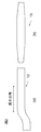
- FIG. 1 shows an example of a mandrel used in the present invention.
- FIG. 1A shows a case where the cross section is uniform in the longitudinal direction
- FIG. 1B shows a case where the cross section changes in the longitudinal direction.
- the mandrel is made by preforming a foam material.
- the foam material used for the mandrel include resins such as urethane, acrylic, and styrene. From the viewpoint of easy removal of the primary laminate from the hollow molded product and low cost, it is made from styrene. It is preferable that it is a polystyrene foam.
- FIG. 2 is a top view of the mandrel longitudinal direction.
- FIG. 2A shows a shape where the molded product is bent in the middle
- FIG. 2B shows a case where the cross-sectional shape of the intermediate portion is large.
- the mandrel made of styrene foam can be dissolved by an organic solvent such as acetone, it can be easily removed in a removing step described later.
- the foaming ratio of the foamed material is preferably 30 times or less, more preferably 10 because a sufficient rigidity as a mandrel is necessary because it is laminated with a braiding machine when the secondary laminate is formed.
- the expansion ratio is ⁇ 30 times.
- the mandrel has a shape that is offset from the outer shape of the molded product (product outer shape), but is preferably a shape that is offset from the product outer shape to a thickness t or more obtained by adding the thickness of the braiding base material to be laminated and the thickness of the pressure bladder. .
- the offset amount is not more than an amount obtained by adding 3 mm to the thickness of the braiding substrate and the thickness of the pressure bladder.
- the braiding substrate will be stiffened no matter how much pressure is applied to the pressure bladder, and the braiding substrate cannot be pressed sufficiently against the mold. This is because voids are formed between the two, and the resin impregnated in the impregnation step described later accumulates in the voids, resulting in a resin-rich portion.
- the braiding base material is additionally reinforced in a part of the secondary laminate in a step other than the second forming step for producing the secondary laminate, there is no problem even if the offset is further offset. .
- FIG. 3 shows an example in which the mandrel has an irregular cross section.
- Various cross-sectional shapes such as an elliptical shape of (a), a shape close to a triangle of (b), and a slender shape of (c) are employed.
- the irregular shape means not circular.
- FIG. 4 shows an example of a cross section of a primary laminate in which a pressure bladder is disposed on a mandrel.
- the pressure bladder serves to transmit the pressure applied in the bladder during molding to the reinforcing fiber
- the material is preferably a silicone rubber or polyamide resin film that is easily deformable and has good releasability. Used.
- the thickness is preferably 0.5 to 2 mm, and in the case of a resin film (for example, FIG. 4 (b)), the thickness is preferably 50 to 150 ⁇ m.
- the shape can be easily expanded and conformed to the outer shape of the mandrel, and any shape can be used as long as the reinforcing fiber can be pressed against the mold by applying internal pressure. It is sufficient that the circumference is equal to or greater than the product circumference, and it is preferable that both the silicone rubber and the resin film have a substantially cylindrical shape capable of continuous molding from the viewpoint of cost.
- the pressurization bladder is closed at the end in the longitudinal direction of the mandrel, in the case of a resin film, the end of the pressurization bladder may be heat-sealed by a commonly used heat sealer or the like. In the case of silicone rubber, the end may be closed using, for example, a binding band.
- a reinforcing laminate is laminated on the outer periphery of the primary laminate while weaving the reinforcing fibers on the braiding substrate to form a secondary laminate.
- a braiding base material means the cylindrical fiber base material obtained by weaving a reinforced fiber with a braiding machine.
- the reinforcing fibers include inorganic fibers such as carbon fibers and glass fibers, and organic fibers such as Kevlar fibers, polyethylene fibers, and polyamide fibers.
- carbon fiber is particularly preferable in terms of light weight and rigidity.
- the braiding base material can be laminated while adjusting the weaving angle of the reinforcing fibers, and the reinforcing fibers are not cut except at the end in the longitudinal direction of the hollow molded product, making it lighter, more rigid, and stronger. Can be obtained.
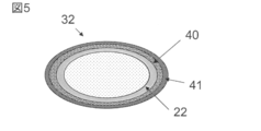
- FIG. 5 shows an example of a cross section of the secondary laminate 32 in which two layers are laminated. 40 is the first layer and 41 is the second layer. Also, when the cross section of the mandrel is changing along the longitudinal direction, when laminating the reinforcing fibers, if the cross section circumference is long, the braid angle is increased, and if the cross section circumference is small By reducing the braid angle, the weave can be controlled, whereby a braiding substrate with a small gap can be produced. Furthermore, the time required for the process can be suppressed to one third or less as compared with the case where the prepreg is manually laminated.
- the obtained secondary laminate 32 is placed in a cavity 60 of a molding die as shown in FIG.
- FIG. 6 shows only the lower mold 50
- the upper mold 51 also has a shape corresponding to the lower mold 50.
- the molding die itself may include a heater (not shown) or a heating medium pipe (not shown), or the molding die is arranged on a press machine having a heat source. Alternatively, the mold itself may be installed on the press machine.
- the molding die is provided with a sealing mechanism (not shown) that prevents the compressed air from leaking at a location 90 where the opening end of the pressurization bladder is disposed, and the flow for evacuating the cavity 60 and discharging the resin.
- a path 70 is provided, and a vacuum pump (not shown) is connected to the end via a discharge tube. Furthermore, a flow path 80 capable of injecting resin into the cavity is provided near the other end of the pressurization bladder, and a resin tank (not shown) capable of injecting resin into the cavity is provided beyond that. Are connected via an injection tube (not shown). Although not shown in the drawing, a sealing mechanism is provided along the outer periphery of the mold that is normally provided and prevents the resin from leaking out of the mold. In order to make the cavity 60 into a vacuum, the channel 80 may be evacuated.
- the heat source of the press machine may be set in advance to the resin curing temperature, and the molding die is heated simultaneously with the pressing.
- the inside of the cavity 60 of the molding die is evacuated by a vacuum pump.
- the resin is supplied from the resin tank to the cavity 60.
- a thermosetting resin such as an epoxy resin is used as the resin that is injected into the cavity and becomes a matrix of the fiber reinforced plastic.
- FIG. 10 to 13 are schematic sectional views in the thickness (up and down) direction of the molding die along the longitudinal direction of the cavity.
- Braiding substrates 40 and 41 are arranged outside the mandrel 10 around which the pressure bladder 22 is wound.
- FIG. 10 is a schematic cross-sectional view in the thickness (up and down) direction of the molding die along the longitudinal direction of the cavity 60 in FIG. 6, and an offset is provided outside the mandrel 10 around which the pressure bladder 22 is wound.
- the braiding substrates 40 and 41 are arranged so that the amount is substantially constant. As shown in FIG. 10, by arranging the offset amount to be substantially constant with respect to the longitudinal direction of the mandrel, the resin flow path is limited and the resin flows efficiently, so that the braiding substrates 40 and 41 are impregnated. It is possible to improve the properties, which is preferable.
- the molding die In addition to making the offset amount constant, at least in some areas in the molding die, it is composed of the shape of the mandrel, the thickness change of the braiding base material (increase / decrease in the base material input amount), and the mold cavity.
- the flow path cross-sectional area of the resin decreases in the offset amount from the resin injection side to the resin discharge side, a region with high resin flow resistance (high flow resistance region) is formed in the mold, It is possible to obtain a hollow molded article made of fiber reinforced plastic in which the injection resin is satisfactorily impregnated into the preform reinforcing fiber base and has almost no resin-impregnated portion and pits.
- the thickness of the braiding base materials 40 and 41 in the thickness direction of the hollow molded product is increased from the resin injection side to the resin discharge side.
- a resin high flow resistance region can be formed. Also, by combining the above-described patterns, it is possible to make a structure in which the offset amount is reduced from the resin injection side toward the resin discharge side.
- the discharge tube 100 connected to the molding die is raised above the molding die. More specifically, it is more preferable that the upper die 51 is located above the highest position of the cavity. By doing so, since the air remaining in the cavity and the slight air contained in the injected resin are pushed out to the tip of the discharge tube, a hollow molded product having a good appearance can be obtained. That is, it is possible to obtain a hollow molded article having a sufficiently good appearance without performing the work of standing up the mold as in Patent Document 2.
- the amount of resin to be supplied is preferably an amount in which a clamp is installed in the discharge tube connected to the molding die to block the discharge of the resin and the resin is filled up to the clamp position 110.
- the use of a mandrel makes it possible to reduce the amount of resin equivalent to the mandrel volume relative to the amount of resin required to fill the mold. ing. Since the utilization rate of the resin can be improved as the clamp position, the position of the discharge tube is preferably as close to the molding die as possible.
- the clamp 110 of the discharge tube is opened, and a predetermined amount of resin is discharged until the weight of the molded product is assumed, so that a higher fiber volume content (high Vf). It becomes possible to make a hollow molded article having What is necessary is just to determine the resin amount to discharge
- the resin is cured by heating for a predetermined time, and the reinforcing fibers and the resin are integrated.
- the mold is removed from the press and the mold is opened.
- a hollow molded article is obtained by taking out a fiber-reinforced plastic hollow molded article from the molding die and removing the primary laminate from the inside. With this molding method, lightweight and high-rigidity fiber reinforced plastic hollow molded products can be easily molded with almost equal thickness, good surface design, even if the cross section is irregular or has a bent part. can do.
- FIG. 8 shows an arrangement state of a plurality of secondary laminates used in another embodiment of the method for forming a hollow molded article according to the present invention. For clarity, FIG. 8 shows only the mandrel shape. As described above, at least two secondary laminates were produced, and as shown in FIG. 8, the two secondary laminates were placed in contact with each other over the entire longitudinal direction and placed in the molding die. By doing so, a hollow molded product having ribs inside can be obtained.
- FIG. 9 shows an arrangement state of a plurality of secondary laminates used in another embodiment of the method for forming a hollow molded product according to the present invention.
- the two secondary laminates are arranged in a molding die with their longitudinal parts in contact with each other. By doing so, it becomes possible to produce a hollow molded product that is bifurcated.
- a reinforcing fiber base material such as carbon fiber is wrapped around the contacted portions of the plurality of secondary laminates of FIGS. 8 and 9 so as to wrap the plurality of secondary laminates as necessary. It is preferable to do. Just by joining the contacted parts, it is weak against the force in the direction of peeling off the two secondary laminates. By reinforcing with a reinforcing fiber base such as a woven fabric, a hollow molded article having more stable strength can be obtained.
- the molding method according to the present invention is suitable for producing a lightweight, high-rigidity hollow molded product having an irregular cross section and having a three-dimensionally bent portion.
- the present invention is not limited to this and can be used even if the cross section is simple.
- the secondary laminate 32 is placed in the cavity 60 of the molding die, and the molding dies 50 and 51 are clamped by a press machine in which the hot platen is set to 80 ° C. in advance, and the inside of the molding die 60, 70, 80, 90 was evacuated.
- the discharge tube 100 is clamped, and a liquid epoxy resin composition containing 100 parts by weight of the epoxy resin and 1 part by weight of the acid anhydride curing agent is cavityd. 60.
- the discharge tube clamp 110 is opened, and an amount of resin equivalent to the expansion volume (increment) of the pressure bladder is discharged, and then the discharge tube 100 is clamped again.
- the resin was cured by heating for 30 minutes in a state where the resin pressure was 0.45 MPa, and the reinforcing fibers and the resin were integrated.
- the molding dies 50 and 51 are taken out from the press machine, the molding die 51 is opened, the fiber-reinforced plastic hollow molded product is taken out from the molding die 50, and the primary laminate 30 is taken from the inside. By removing, a hollow molded article was obtained.
- the amount of resin used in the non-product part is minimized, the wall thickness is almost equal, the surface design is good, and the fiber reinforcement with no resin-impregnated part and almost no pits. It was recognized that a plastic hollow molded product can be obtained.
Landscapes
- Engineering & Computer Science (AREA)
- Mechanical Engineering (AREA)
- Chemical & Material Sciences (AREA)
- Composite Materials (AREA)
- Casting Or Compression Moulding Of Plastics Or The Like (AREA)
- Moulding By Coating Moulds (AREA)
- Reinforced Plastic Materials (AREA)
Abstract
Description
20,21,22・・・加圧用ブラダー
30,31・・・1次積層体
32・・・2次積層体
40,41・・・ブレーディング基材
50,51・・・成形金型
60・・・キャビティ
70,80・・・流路
90・・・加圧用ブラダー開口端部
100・・・排出チューブ
110・・・クランプ位置
Claims (13)
- 繊維強化プラスチックから構成される中空成形品を成形する方法であって、
発泡材を予備成形し、成形品外形からオフセットした形状を有するマンドレルに、加圧用ブラダーを配置して、1次積層体を形成する第1の形成工程と、
前記1次積層体の外周に、強化繊維をブレーディングマシンでブレーディング基材に製織しながら積層して2次積層体を形成する第2の形成工程と、
前記2次積層体を成形金型内に配置する配置工程と、
成形金型内に樹脂を注入する注入工程と、
成形型内に配置した2次積層体の加圧用ブラダー内に圧力を付与しながら、加熱により強化繊維と樹脂を一体化する一体化工程と、
一体化した成形品から1次積層体を除去する除去工程と、
を含む、中空成形品の成形方法。 - 成形金型が、成形金型内から樹脂を排出できる排出チューブに接続されており、前記注入工程において、当該排出チューブの少なくとも一部を成形金型より高い位置に配置する、請求項1に記載の中空成形品の成形方法。
- 成形金型が、成形金型内から樹脂を排出でき、かつ樹脂の排出を塞き止めるためのクランプを有する排出チューブに接続されており、前記注入工程において、注入する樹脂量が、排出チューブのクランプ位置まで樹脂で実質的に埋まる樹脂量である、請求項1または2に記載の中空成形品の成形方法。
- 前記一体化工程において、成形品が想定される重量になるまで樹脂を排出する、請求項1~3のいずれかに記載の中空成形品の成形方法。
- 発泡材が発泡スチロールである、請求項1~4のいずれかに記載の中空成形品の成形方法。
- 前記2次積層体を少なくとも2体作製し、前記配置工程において、それら2次積層体を長手方向全体に渡って相互に接触させて成形金型に配置する、請求項1~5のいずれかに記載の中空成形品の成形方法。
- 前記2次積層体を少なくとも2体作製し、前記配置工程において、それら2次積層体を、その長手方向の一部を相互に接触させて成形金型に配置する、請求項1~5のいずれかに記載の中空成形品の成形方法。
- 複数作製した2次積層体の相互に接触させた部分の少なくとも一部を強化繊維基材で補強する、請求項6または7に記載の中空成形品の成形方法。
- マンドレルの成形品外形からのオフセット量が一定である、請求項1~8のいずれかに記載の中空成形品の成形方法。
- 成形金型内の少なくとも一部の領域において、マンドレルの成形品外形からのオフセット量が、樹脂注入側から樹脂排出側に向けて減少する構成を有する、請求項1~8のいずれかに記載の中空成形品の成形方法。
- 成形金型内の少なくとも一部の領域において、成形金型内の中空成形品厚み方向におけるブレーディング基材の厚みが樹脂注入側から樹脂排出側に向けて増加する構成を有する、請求項10に記載の中空成形品の成形方法。
- 成形金型内における少なくとも一部の領域において、金型のキャビティの断面積が樹脂注入側から樹脂排出側に向けて縮小する構造を有する、請求項10に記載の中空成形品の成形方法。
- 請求項1~12のいずれかに記載の中空成形品の成形方法を用いた繊維強化プラスチックの製造方法。
Priority Applications (2)
| Application Number | Priority Date | Filing Date | Title |
|---|---|---|---|
| CN201480004321.7A CN104903076A (zh) | 2013-01-24 | 2014-01-20 | 中空成型品的成型方法及纤维增强塑料的制造方法 |
| JP2014515741A JPWO2014115668A1 (ja) | 2013-01-24 | 2014-01-20 | 中空成形品の成形方法および繊維強化プラスチックの製造方法 |
Applications Claiming Priority (4)
| Application Number | Priority Date | Filing Date | Title |
|---|---|---|---|
| JP2013-010970 | 2013-01-24 | ||
| JP2013010970 | 2013-01-24 | ||
| JP2013246067 | 2013-11-28 | ||
| JP2013-246067 | 2013-11-28 |
Publications (1)
| Publication Number | Publication Date |
|---|---|
| WO2014115668A1 true WO2014115668A1 (ja) | 2014-07-31 |
Family
ID=51227459
Family Applications (1)
| Application Number | Title | Priority Date | Filing Date |
|---|---|---|---|
| PCT/JP2014/050908 Ceased WO2014115668A1 (ja) | 2013-01-24 | 2014-01-20 | 中空成形品の成形方法および繊維強化プラスチックの製造方法 |
Country Status (4)
| Country | Link |
|---|---|
| JP (1) | JPWO2014115668A1 (ja) |
| CN (1) | CN104903076A (ja) |
| TW (1) | TW201434613A (ja) |
| WO (1) | WO2014115668A1 (ja) |
Cited By (3)
| Publication number | Priority date | Publication date | Assignee | Title |
|---|---|---|---|---|
| CN110978563A (zh) * | 2019-08-28 | 2020-04-10 | 佛山市顺德区迈进机械制造有限公司 | 一种热压成型机 |
| KR102358500B1 (ko) * | 2020-12-29 | 2022-02-08 | 한국항공대학교산학협력단 | 복합재 중공 구조체 성형 방법 및 장치, 그에 의해 제조된 복합재 중공 구조체 |
| JP2022520917A (ja) * | 2018-12-11 | 2022-04-04 | ゼネラル・エレクトリック・カンパニイ | 繊維強化ポリマー複合ビーム、とくには風力タービンロータブレード用の桁ビームを製造するための方法 |
Families Citing this family (2)
| Publication number | Priority date | Publication date | Assignee | Title |
|---|---|---|---|---|
| TWI661965B (zh) * | 2018-12-12 | 2019-06-11 | 財團法人自行車暨健康科技工業研究發展中心 | Bicycle component capable of improving structural rigidity |
| CN110001080A (zh) * | 2019-05-07 | 2019-07-12 | 航天神舟飞行器有限公司 | 一种应用于无人机的异形支撑结构零件制造方法 |
Citations (11)
| Publication number | Priority date | Publication date | Assignee | Title |
|---|---|---|---|---|
| JPH0321434A (ja) * | 1989-06-19 | 1991-01-30 | Nippon Steel Corp | 繊維強化プラスチックパイプの製造方法 |
| JPH04265714A (ja) * | 1991-02-21 | 1992-09-21 | Kawasaki Heavy Ind Ltd | 中空複合部材の製造方法 |
| JPH0839692A (ja) * | 1994-07-29 | 1996-02-13 | Yokohama Rubber Co Ltd:The | 自転車用フロントフォークの製造方法 |
| JPH11192991A (ja) * | 1998-01-06 | 1999-07-21 | Exedy Corp | 自転車用frp製モノコックフレ−ムの構造及びその製造方法 |
| JP2001030360A (ja) * | 1999-07-21 | 2001-02-06 | Shingo Mase | 繊維強化樹脂よりなる複合管状物及びその製造方法 |
| JP2004017412A (ja) * | 2002-06-14 | 2004-01-22 | Murata Mach Ltd | 曲がりパイプの製造方法 |
| JP2008073876A (ja) * | 2006-09-19 | 2008-04-03 | Toray Ind Inc | 中空frpの製造方法 |
| WO2009078419A1 (ja) * | 2007-12-17 | 2009-06-25 | Toyota Jidosha Kabushiki Kaisha | 繊維強化樹脂中空部品の成形方法 |
| JP2009202440A (ja) * | 2008-02-28 | 2009-09-10 | Toray Ind Inc | 繊維強化プラスチックの脱型方法、製造方法 |
| JP2012066397A (ja) * | 2010-09-21 | 2012-04-05 | Toray Ind Inc | 繊維強化プラスチックの製造方法 |
| WO2012115067A1 (ja) * | 2011-02-25 | 2012-08-30 | 東レ株式会社 | Frpの製造方法 |
Family Cites Families (4)
| Publication number | Priority date | Publication date | Assignee | Title |
|---|---|---|---|---|
| TWI296237B (en) * | 2004-12-08 | 2008-05-01 | Chung Shan Inst Of Science | Hollow composite material structure and fabricating method thereof |
| CN101786329A (zh) * | 2009-01-22 | 2010-07-28 | 李世鹏 | 强化碳纤维自行车组件的成型方法 |
| US8303882B2 (en) * | 2009-02-23 | 2012-11-06 | General Electric Company | Apparatus and method of making composite material articles |
| FR2957845B1 (fr) * | 2010-03-26 | 2012-08-10 | Messier Dowty Sa | Procede de fabrication d'un bras en materiau composite comportant un palier transversal destine a recevoir un axe fixe ou rotatif |
-
2014
- 2014-01-20 JP JP2014515741A patent/JPWO2014115668A1/ja active Pending
- 2014-01-20 WO PCT/JP2014/050908 patent/WO2014115668A1/ja not_active Ceased
- 2014-01-20 CN CN201480004321.7A patent/CN104903076A/zh active Pending
- 2014-01-23 TW TW103102436A patent/TW201434613A/zh unknown
Patent Citations (11)
| Publication number | Priority date | Publication date | Assignee | Title |
|---|---|---|---|---|
| JPH0321434A (ja) * | 1989-06-19 | 1991-01-30 | Nippon Steel Corp | 繊維強化プラスチックパイプの製造方法 |
| JPH04265714A (ja) * | 1991-02-21 | 1992-09-21 | Kawasaki Heavy Ind Ltd | 中空複合部材の製造方法 |
| JPH0839692A (ja) * | 1994-07-29 | 1996-02-13 | Yokohama Rubber Co Ltd:The | 自転車用フロントフォークの製造方法 |
| JPH11192991A (ja) * | 1998-01-06 | 1999-07-21 | Exedy Corp | 自転車用frp製モノコックフレ−ムの構造及びその製造方法 |
| JP2001030360A (ja) * | 1999-07-21 | 2001-02-06 | Shingo Mase | 繊維強化樹脂よりなる複合管状物及びその製造方法 |
| JP2004017412A (ja) * | 2002-06-14 | 2004-01-22 | Murata Mach Ltd | 曲がりパイプの製造方法 |
| JP2008073876A (ja) * | 2006-09-19 | 2008-04-03 | Toray Ind Inc | 中空frpの製造方法 |
| WO2009078419A1 (ja) * | 2007-12-17 | 2009-06-25 | Toyota Jidosha Kabushiki Kaisha | 繊維強化樹脂中空部品の成形方法 |
| JP2009202440A (ja) * | 2008-02-28 | 2009-09-10 | Toray Ind Inc | 繊維強化プラスチックの脱型方法、製造方法 |
| JP2012066397A (ja) * | 2010-09-21 | 2012-04-05 | Toray Ind Inc | 繊維強化プラスチックの製造方法 |
| WO2012115067A1 (ja) * | 2011-02-25 | 2012-08-30 | 東レ株式会社 | Frpの製造方法 |
Cited By (5)
| Publication number | Priority date | Publication date | Assignee | Title |
|---|---|---|---|---|
| JP2022520917A (ja) * | 2018-12-11 | 2022-04-04 | ゼネラル・エレクトリック・カンパニイ | 繊維強化ポリマー複合ビーム、とくには風力タービンロータブレード用の桁ビームを製造するための方法 |
| US11628634B2 (en) | 2018-12-11 | 2023-04-18 | General Electric Company | Method for manufacturing a fiber reinforced polymer composite beam, particularly a spar beam for a wind turbine rotor blade |
| JP7282890B2 (ja) | 2018-12-11 | 2023-05-29 | ゼネラル・エレクトリック・カンパニイ | 繊維強化ポリマー複合ビーム、とくには風力タービンロータブレード用の桁ビームを製造するための方法 |
| CN110978563A (zh) * | 2019-08-28 | 2020-04-10 | 佛山市顺德区迈进机械制造有限公司 | 一种热压成型机 |
| KR102358500B1 (ko) * | 2020-12-29 | 2022-02-08 | 한국항공대학교산학협력단 | 복합재 중공 구조체 성형 방법 및 장치, 그에 의해 제조된 복합재 중공 구조체 |
Also Published As
| Publication number | Publication date |
|---|---|
| CN104903076A (zh) | 2015-09-09 |
| TW201434613A (zh) | 2014-09-16 |
| JPWO2014115668A1 (ja) | 2017-01-26 |
Similar Documents
| Publication | Publication Date | Title |
|---|---|---|
| JP6140679B2 (ja) | 再使用可能なレジン分配ラインを具備する真空を利用したレジン注入成形プロセス | |
| JP6557972B2 (ja) | 繊維強化プラスチックの製造方法および製造装置 | |
| CN107548341B (zh) | 纤维增强塑料成型体的制造方法 | |
| TWI494204B (zh) | 纖維強化塑膠結構體的成形方法 | |
| CA2935481C (en) | Frp shaping jig and method of shaping frp structure | |
| JP4384221B2 (ja) | 繊維強化樹脂中空部品の成形方法 | |
| CN110914046B (zh) | 多阶段树脂输送 | |
| JP2005534533A5 (ja) | ||
| JP2013532596A (ja) | 連続強化繊維層を備えた成形プラスチック多層構成部品およびその製造方法 | |
| WO2014115668A1 (ja) | 中空成形品の成形方法および繊維強化プラスチックの製造方法 | |
| JP2016535689A (ja) | 発泡コアを備えたサンドイッチ構造の異形材の連続式製造方法及び硬質発泡体を充填した異形材 | |
| CN110682560A (zh) | 纤维增强塑料的成型方法 | |
| US10307975B2 (en) | Resin-infusion process for composites manufacturing | |
| KR20170007883A (ko) | 중공 타입 복합재의 성형용 몰드 및 중공 타입 복합재의 성형 방법 | |
| JP4292971B2 (ja) | Frpの製造方法および製造装置 | |
| KR101447136B1 (ko) | 섬유 강화 복합재의 성형방법 | |
| KR20120020721A (ko) | 튜브없이 공기팽창식으로 몰딩하는 복합재 중공구조물 제조방법 | |
| JP7618465B2 (ja) | 釣用ガイドフレーム | |
| KR20150062195A (ko) | 탄소섬유강화플라스틱 가압 성형장치 및 탄소섬유강화플라스틱 가압 성형방법 | |
| JP4382869B2 (ja) | フランジ付き繊維強化樹脂中空部品の成形方法 | |
| EP4351869B1 (en) | Method for producing fiber composite parts | |
| KR101561029B1 (ko) | 차량용 헬멧 제조방법 | |
| JP7618464B2 (ja) | 釣用ガイドフレーム、および釣用ガイドフレームの製造方法 | |
| JP4508618B2 (ja) | バッグ成形法 | |
| JP2016135573A (ja) | 複合材料の成形方法および成形装置 |
Legal Events
| Date | Code | Title | Description |
|---|---|---|---|
| ENP | Entry into the national phase |
Ref document number: 2014515741 Country of ref document: JP Kind code of ref document: A |
|
| 121 | Ep: the epo has been informed by wipo that ep was designated in this application |
Ref document number: 14743138 Country of ref document: EP Kind code of ref document: A1 |
|
| NENP | Non-entry into the national phase |
Ref country code: DE |
|
| WWE | Wipo information: entry into national phase |
Ref document number: IDP00201505121 Country of ref document: ID |
|
| 122 | Ep: pct application non-entry in european phase |
Ref document number: 14743138 Country of ref document: EP Kind code of ref document: A1 |