WO2014115661A1 - スエージ装置 - Google Patents
スエージ装置 Download PDFInfo
- Publication number
- WO2014115661A1 WO2014115661A1 PCT/JP2014/050886 JP2014050886W WO2014115661A1 WO 2014115661 A1 WO2014115661 A1 WO 2014115661A1 JP 2014050886 W JP2014050886 W JP 2014050886W WO 2014115661 A1 WO2014115661 A1 WO 2014115661A1
- Authority
- WO
- WIPO (PCT)
- Prior art keywords
- joint
- swage
- detection mechanism
- sliding surface
- main body
- Prior art date
- Legal status (The legal status is an assumption and is not a legal conclusion. Google has not performed a legal analysis and makes no representation as to the accuracy of the status listed.)
- Ceased
Links
Images




Classifications
-
- B—PERFORMING OPERATIONS; TRANSPORTING
- B21—MECHANICAL METAL-WORKING WITHOUT ESSENTIALLY REMOVING MATERIAL; PUNCHING METAL
- B21D—WORKING OR PROCESSING OF SHEET METAL OR METAL TUBES, RODS OR PROFILES WITHOUT ESSENTIALLY REMOVING MATERIAL; PUNCHING METAL
- B21D39/00—Application of procedures in order to connect objects or parts, e.g. coating with sheet metal otherwise than by plating; Tube expanders
- B21D39/04—Application of procedures in order to connect objects or parts, e.g. coating with sheet metal otherwise than by plating; Tube expanders of tubes with tubes; of tubes with rods
- B21D39/048—Application of procedures in order to connect objects or parts, e.g. coating with sheet metal otherwise than by plating; Tube expanders of tubes with tubes; of tubes with rods using presses for radially crimping tubular elements
Definitions
- the present invention relates to a swage device.
- ⁇ A joint is used to connect two pipes. At the time of connection, the end of each pipe is inserted into the joint. After insertion, the joint is crimped (swaged). Thereby, two pipes are connected via a joint.
- Patent Document 1 Japanese Patent Publication No. 9-5012264 discloses an attachment part that is attached to a pipe by swaging.
- This mounting part comprises a cylindrical sleeve.
- the sleeve has a tapered outer surface and an inner surface that receives the tube.
- the swage ring engages the outer surface of the sleeve and the ring moves axially forward with respect to the sleeve, the ring applies a radial force against the sleeve and is swaged.
- Patent Document 2 Japanese Patent Laid-Open No. 2-182329 discloses a swaging tool.
- the swaging tool supports a first die, a second die that can move toward the first die, a head that holds the first die relative to the second die during swaging, and a second die.
- a cylinder having means for moving the second die toward the first die.
- Patent Document 3 Japanese Patent No. 2887589 discloses a swage tool.
- the swage tool includes a housing, a piston movable in an axial direction facing the housing, and a first engagement member fixed on the housing, and one of the ring and the sleeve moves in the axial direction.
- a second coupling member coupled to the piston so as to move together with the piston when the piston moves in the axial direction relative to the housing.
- a second engaging member that moves in the axial direction toward the first engaging member.
- Patent Document 4 Japanese Patent Publication No. 10-5118957 discloses an axial swage tool having a stabilizing pin.
- the swage device is inspected as necessary. For example, the state of use of the internal mechanism of the swage device is confirmed by overhaul. For example, by using a measuring tool, the clearance between main parts, the operation of the swage device when pressure is applied, and the like are inspected. As a result of the inspection, the usage status (degradation level, etc.) of the swage device is determined, and some parts of the swage device are replaced as necessary.
- an object of the present invention is to provide a swage device that can easily know the usage status of the swage device.
- the swage device includes a main body that supports a joint, a push member that is supported by the main body, and applies a force to the joint along a first direction so that the joint is crimped.
- a use frequency detection mechanism for detecting the inspection time of the main body.
- a swage device that can easily know the usage status of the swage device.
- FIG. 1 is a schematic view showing a joint.
- FIG. 2 is a perspective view schematically showing the swage device.
- FIG. 3 is a schematic view showing an operation during caulking.
- FIG. 4 is a schematic cross-sectional view showing a sliding surface.
- FIG. 5 is a diagram illustrating a modification of the first embodiment.
- FIG. 6 is a diagram illustrating another modification of the first embodiment.
- FIG. 7 is a perspective view schematically showing a swage device according to the second embodiment.
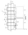
- FIG. 1 is a schematic view showing the joint 1.
- the joint 1 is used to connect the pipe 2-1 and the pipe 2-2.
- the pipe 2-1 and the pipe 2-2 are pipes arranged in the aircraft.
- the pipe 2 does not necessarily have to be for aircraft, and the present embodiment can be applied to other uses.
- the joint 1 includes a sleeve 3 (first member) and a pair of swage rings 4 (4-1, 4-2; second member).
- the sleeve 3 is cylindrical. The end of each tube 2 is inserted into the sleeve 3. Tapered portions 6 (6-1, 6-2) are provided at both ends of the sleeve 3. In the taper portion 6, the outer diameter of the sleeve 3 is smaller toward the tip side.
- the sleeve 3 is provided with a pair of stoppers (5-1, 5-2). Each stopper 5 is provided to limit the movement of the swaging ring 4. Each stopper 5 is provided at a proximal end portion of each tapered portion 6.
- the pair of swage rings 4 are arranged at both ends of the sleeve 3.
- Each swaging ring 4 is annular and is arranged so as to be coaxial with the sleeve 3.
- Each swage ring 4 has an end of the sleeve 3 inserted therein.
- the inner diameter of each swage ring 4 is larger than the outer diameter at the distal end portion of the tapered portion 6 and smaller than the outer diameter at the proximal end portion of the tapered portion 6.
- the swage ring 4 When swaging the joint 1, the swage ring 4 is moved relative to the sleeve 3 along the axis c of the joint 1.
- the swaging ring 4 may be moved while the sleeve 3 is fixed, or the sleeve 3 may be moved while the swaging ring 4 is fixed.
- the swage ring 4 is pushed in until it hits each stopper 5. Thereby, the sleeve 3 is compressed in the taper part 6, and each inserted pipe
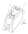
- FIG. 2 is a perspective view schematically showing the swage device 7.
- the swage device 7 includes a main body portion 8, a yoke 9 (pushing member), and a usage frequency detection mechanism 11.
- the main body portion 8 is a portion that supports the joint 1.
- the main body 8 has an upper surface 24.
- the upper surface 24 is provided with a groove 25 extending along the first direction.
- the groove 25 has such a shape that the joint 1 into which the pipe 2 is inserted can be disposed. That is, when viewed from the first direction, the groove 25 has a semicircular shape. Further, the bottom surface of the groove 25 forms a sliding surface 14. Further, a stopper 10 is provided at an end portion of the groove 25 along the first direction. The stopper 10 has a function of restricting the joint 1 from moving in the first direction.
- a hydraulic device 18 (hydraulic cylinder) is provided in the main body 8.
- a hydraulic pipe 19 is connected to the hydraulic device 18.
- the hydraulic device 18 includes a piston rod (not shown). The piston rod is movable in the first direction by the hydraulic pressure applied via the hydraulic pipe 19.
- the yoke 9 is disposed on the sliding surface 14.
- the yoke 9 is supported by the main body 8 and can slide on the sliding surface 14 along the first direction.
- the yoke 9 is connected to a hydraulic device 18 (piston rod) through an opening (not shown) provided in the sliding surface 14. The opening extends along the first direction.
- the yoke 9 is moved along the first direction by the hydraulic device 18.
- the yoke 9 is provided with a stopper 15 and a mounting surface 12. A part of the joint 1 is placed on the placement surface 12.
- the stopper 15 is a part that contacts the joint 1 (the swage ring 4 or the stopper 5).
- the usage frequency detection mechanism 11 has a function of detecting the usage frequency (usage) of the swage device 7.
- the use frequency detection mechanism 11 also functions as an inspection time detection mechanism (maintenance time detection mechanism) that detects the inspection time of the swage device 7.
- the usage frequency detection mechanism 11 is provided on the sliding surface 14.
- FIG. 3 is a schematic diagram showing the operation during caulking.
- the joint 1 is placed on the main body portion 8.
- the joint 1 is placed so that the axis c is along the first direction. Further, the joint 1 is placed so that the swage ring 4 and the stopper 5 to be crimped between the yoke 9 and the stopper 10 are located.
- a part of the joint 1 is placed on the placement surface 12 of the yoke 9.
- the yoke 9 is moved along the first direction. At this time, one of the swage ring 4 and the stopper 5 is pushed by the yoke 9 (stopper 15). The other of the swaging ring 4 and the stopper 5 is restricted by the stopper 10 from moving in the first direction.
- the yoke 9 is in contact with the swage ring 4-1, and the stopper 10 is in contact with the stopper 5-1. Therefore, the yoke 9 is pushed in the first direction until the swaging ring 4-1 hits the stopper 5-1. Thereby, the taper part 6-1 is compressed and the joint 1 is crimped.
- the other taper part 6-2 is crimped. That is, as shown by a dotted line in FIG. 3, the arrangement is changed so that the yoke 9 contacts the stopper 5-2 and the stopper 10 contacts the swage ring 4-2. Then, the yoke 9 is moved in the first direction. As a result, the stopper 5-2 is pushed in until it hits the swage ring 4-2.
- the swaging device 7 can be reversed, the stopper 10 can be brought into contact with the stopper 5-2 in the same manner as the swaging ring 4-1, and the swaging ring 4-2 can be pushed in. Thereby, the taper part 6-2 is crimped. As described above, the pipe 2-1 and the pipe 2-2 are connected in an airtight or watertight manner via the joint 1.
- the usage of the swage device 7 is detected by the usage frequency detection mechanism 11.
- the operator can determine whether or not component replacement is necessary based on the detection result. Since the use frequency detection mechanism 11 is provided, the timing of component replacement can be easily grasped. Hereinafter, the use frequency detection mechanism 11 will be described in detail.
- the use frequency detection mechanism 11 is realized by a mechanism (a wear degree detection mechanism) that detects the wear degree of the sliding surface.
- FIG. 4 is a schematic cross-sectional view showing the sliding surface 14 and is a schematic view showing a wear degree detection mechanism.
- the colored layer 13 is provided as a wear degree detection mechanism.
- the colored layer 13 falls off according to the wear of the sliding surface 14.
- the operator can know the degree of wear of the sliding surface 14.
- the degree of wear reflects the number of sliding of the yoke 9. That is, the wear level reflects the usage of the swage device 7. By detecting the degree of wear, the usage of the swage device 7 can be roughly detected, and the timing of component replacement can be grasped.
- the wear level detection mechanism is not limited to the colored layer 13. Other configurations may be employed as the wear degree detection mechanism as long as the wear degree can be detected.
- FIG. 5 is a diagram showing a modification of the present embodiment.
- a fine recess 16 provided on the sliding surface 14 is used as the use frequency detection mechanism 11.
- the depth of the recess 16 decreases. Therefore, the wear degree can be detected by visually recognizing the recess 16 and grasping the depth of the recess 16.
- FIG. 6 is a diagram showing another modification of the present embodiment.
- a convex portion 17 is provided on the sliding surface 14 as the usage frequency detection mechanism 11.
- the convex portion 17 is fine and has a height that does not substantially interfere with the yoke 9 when sliding.
- the height of the convex portion 17 decreases. Therefore, the wear degree can be detected by grasping the height of the convex portion 17 by visual recognition.
- the wear degree detection mechanism is provided as the use frequency detection mechanism 11, the wear degree of the sliding surface 14 can be visually confirmed. Therefore, it is possible to grasp the timing of component replacement (repair) without using an auxiliary tool. Also, there is no need for overhaul.
- the hydraulic device 18 can move the yoke 9 in the present embodiment, the case where the hydraulic device 18 can move the yoke 9 has been described.
- the yoke 9 is not necessarily moved by the hydraulic device 18, and another device may be configured to move the yoke 9.
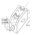
- FIG. 7 is a perspective view schematically showing the swage device 7 according to the present embodiment.
- the configuration of the usage frequency detection mechanism 11 is changed with respect to the first embodiment.
- a notification mechanism 23 is added.
- the structure similar to 1st Embodiment is employable, detailed description is abbreviate
- the usage frequency detection mechanism 11 includes a pressure measurement mechanism 22 and a counting mechanism 21.
- the pressure measuring mechanism 22 is connected to the hydraulic pipe 19 and has a function of measuring the pressure (hydraulic pressure) in the hydraulic pipe 19.
- the counting mechanism 21 has a function of detecting the number of times the joint 1 is crimped (the number of times the swage device 7 is used) based on the measurement result by the pressure measuring mechanism 22.
- the yoke 9 is moved by the hydraulic device 18. Accordingly, when the yoke 9 moves, the hydraulic pressure of the hydraulic pipe 19 changes. Therefore, the pressure measurement mechanism 22 can detect the number of times the joint 1 has been crimped based on the measurement result of the hydraulic pressure.
- a threshold pressure is set in advance in the pressure measurement mechanism 22.
- the pressure measurement mechanism 22 compares the threshold pressure with the hydraulic pressure that is the detection result.
- the counting mechanism 21 counts the number of times the hydraulic pressure has exceeded the threshold pressure as the number of times the joint 1 has been crimped based on the comparison result by the pressure measuring mechanism 22.
- the number of times counted by the counting mechanism 21 is transmitted to the operator via an output device (display device, audio output device, etc.) not shown. Thereby, the operator can know the number of times the swage device 7 is used, and can grasp the timing of parts replacement without performing an overhaul and the like as in the above-described embodiment.
- the notification mechanism 23 is provided for notifying whether or not an appropriate pressure is applied to the hydraulic pipe 19 during caulking.
- the notification mechanism 23 determines whether or not the pressure in the hydraulic piping 19 is equal to or higher than a predetermined set pressure based on the measurement result by the pressure measurement mechanism 22 and notifies the determination result.
- the notification mechanism 23 is realized by, for example, a display device (such as a lamp) and a sound output device.
- the set pressure may be the same as or different from the threshold pressure set in the counting mechanism 21.
- the number of uses of the swage device 7 and the degree of deterioration of the hydraulic device 18 can be grasped without performing an overhaul and the like as in the first embodiment.
- tool inspection and component replacement can be performed at an appropriate timing. Since it is possible to know an appropriate timing for parts replacement or the like, particularly in a large-scale site where a plurality of swage devices 7 are used at the same time, the time required for overhauling can be greatly reduced. Moreover, since the timing of parts replacement can be grasped without disassembling the apparatus, it is possible to suppress the occurrence of work delays due to apparatus defects.
- the present invention has been described above using the first and second embodiments. Note that these embodiments are not independent and can be used in combination within a consistent range.
- all of the wear degree detection mechanism, the pressure measurement mechanism, and the counting mechanism may be provided as the usage frequency detection mechanism.
- JP2013-011299 This application claims convention priority based on the Japanese patent application number (JP2013-011299). That disclosure is incorporated herein by reference.
Landscapes
- Engineering & Computer Science (AREA)
- Mechanical Engineering (AREA)
- Non-Disconnectible Joints And Screw-Threaded Joints (AREA)
Abstract
簡単にスエージ装置の使用状況を知ることができる、スエージ装置を提供すること。スエージ装置(7)は、継手(1)を支持する本体部(8)と、本体部(8)により支持され、継手(1)が加締められるように、第1方向に沿って前記継手(1)に力を加える押込部材(9)と、継手(1)が加締められた回数を検出する使用頻度検出機構(11)とを備える。
Description
本発明は、スエージ装置に関する。
2本の管を接続するために継手が用いられる。接続時には、各管の端部が継手に挿入される。挿入後、継手が加締められる(スエージされる)。これにより、継手を介して2本の管が接続される。
継手に関連して、特許文献1(特表平9-501224号公報)には、スエージ加工によって管に取り付けられる取り付け部品が開示されている。この取り付け部品は、円筒形のスリーブを備える。スリーブは、テーパ付きの外面と、管を受容する内面を有する。スエージ加工リングがスリーブの外面に係合し、リングがスリーブに対して前方向へ軸に動くと、リングがスリーブに対して半径方向の力を加え、スエージ加工される。
一方、継手を加締める場合に、スエージ装置が用いられる場合がある。スエージ装置に関連して、特許文献2(特開平2-182329号公報)には、スエージングツールが開示されている。このスエージングツールは、第1ダイと、第1ダイに向かって移動できる第2ダイと、スエージ加工中に第2ダイに対して第1ダイを保持しておくヘッドと、第2ダイを支持するシリンダであって、第1ダイに向かって第2ダイを移動させる手段を備えるシリンダとを有している。
また、特許文献3(特許第2875889号公報)には、スエージ工具が開示されている。このスエージ工具は、ハウジングと、ハウジングに対して相対する軸線方向に移動可能なピストンと、ハウジング上に固定された第1の係合部材であって、リング及びスリーブの一方が軸線方向に移動するのを拘束する第1の係合部材と、ピストンと共に移動するようにピストンに結合された第2の結合部材であって、ピストンがハウジングに対して軸線方向に移動した際、リング及びスリーブの他方を第1の係合部材に向けて軸線方向に移動させる第2の係合部材とを有している。
更に、特許文献4(特表平10-511897号公報)には、安定化ピンを有する軸スエージ工具が開示されている。
スエージ装置が正常に動作しなければ、継手を適切に加締めることができない。そこで、スエージ装置は、必要に応じて点検される。例えば、分解点検により、スエージ装置の内部機構の使用状況が確認される。例えば、計測用工具を用いることにより、主要部品間の隙間や、圧力を加えたときのスエージ装置の動作などが点検される。点検の結果、スエージ装置の使用状況(劣化度など)が判断され、必要に応じてスエージ装置の一部の部品が交換される。
しかしながら、スエージ装置の使用状況を知るためには、分解点検や計測用工具が必要である。そこで、本発明の課題は、簡単にスエージ装置の使用状況を知ることができるスエージ装置を提供することにある。
本発明に係るスエージ装置は、継手を支持する、本体部と、前記本体部により支持され、前記継手が加締められるように、第1方向に沿って前記継手に力を加える押込部材と、前記本体部の点検時期を検出する使用頻度検出機構とを備える。
本発明によれば、簡単にスエージ装置の使用状況を知ることができるスエージ装置が提供される。
以下、図面を参照しつつ、本発明の実施形態について説明する。
[第1の実施形態]
まず、本実施形態に係るスエージ装置により加締められる継手1について説明する。
まず、本実施形態に係るスエージ装置により加締められる継手1について説明する。
図1は、継手1を示す概略図である。継手1は、管2-1と管2-2とを接続するために用いられる。本実施形態では、管2-1及び管2-2は、航空機内に配置される配管であるものとする。但し、管2は必ずしも航空機用である必要はなく、本実施形態は他の用途にも適用可能である。
図1に示されるように、継手1は、スリーブ3(第1部材)及び一対のスエージリング4(4-1、4-2;第2部材)を備えている。
スリーブ3は、円筒状である。スリーブ3には、各管2の端部が挿入される。スリーブ3の両端部には、テーパ部6(6-1、6-2)が設けられている。テーパ部6では、先端側ほどスリーブ3の外径が小さくなっている。また、スリーブ3には、一対のストッパ(5-1、5-2)が設けられている。各ストッパ5は、スエージリング4の移動を制限するために設けられている。各ストッパ5は、各テーパ部6の基端部に設けられている。
一対のスエージリング4は、スリーブ3の両端部に配置される。各スエージリング4は、環状であり、スリーブ3と同軸になるように配置される。各スエージリング4には、スリーブ3の端部が挿入されている。各スエージリング4の内径は、テーパ部6の先端部における外径より大きく、テーパ部6の基端部における外径より小さい。
継手1を加締める際には、スエージリング4が、継手1の軸cに沿ってスリーブ3に対して相対的に移動させられる。スリーブ3が固定された状態でスエージリング4が移動させられる場合もあれば、スエージリング4が固定された状態でスリーブ3が移動させられる場合もある。スエージリング4は、各ストッパ5に突き当たるまで、押し込まれる。これにより、テーパ部6においてスリーブ3が圧縮され、挿入された各管2が締め付けられる。すなわち、継手1が加締められる。
続いて、継手1を加締めるためのスエージ装置について説明する。まず、スエージ装置の概略構成について説明する。
図2は、スエージ装置7を概略的に示す斜視図である。図2に示されるように、スエージ装置7は、本体部8、ヨーク9(押込部材)、及び使用頻度検出機構11を有している。
本体部8は、継手1を支持する部分である。本体部8は、上面24を有している。上面24には、第1方向に沿って延びる溝25が設けられている。溝25は、管2が挿入された継手1を配置することができるような形状を有している。すなわち、第1方向から見た場合に、溝25は、半円状である。また、溝25の底面は、摺動面14を形成している。更に、溝25の第1方向に沿う端部には、ストッパ10が設けられている。ストッパ10は、継手1が第1方向に移動することを制限する機能を有している。
さらに、本体部8内には、油圧装置18(油圧シリンダー)が設けられている。油圧装置18には、油圧配管19が接続されている。油圧装置18は、図示しないピストンロッドを備えている。油圧配管19を介して加えられる油圧により、ピストンロッドが第1方向に沿って移動可能する。
ヨーク9は、摺動面14上に配置されている。ヨーク9は、本体部8により支持されており、第1方向に沿って摺動面14上を摺動可能である。具体的には、ヨーク9は、摺動面14に設けられた開口(図示せず)を介して油圧装置18(ピストンロッド)に連結されている。開口は第1方向に沿って延びている。ヨーク9は油圧装置18によって第1方向に沿って移動する。
また、ヨーク9には、ストッパ15、及び載置面12が設けられている。載置面12には、継手1の一部が載せられる。ストッパ15は、継手1(スエージリング4又はストッパ5)に接触する部分である。
使用頻度検出機構11は、スエージ装置7の使用頻度(使用度)を検出する機能を有している。使用頻度検出機構11は、スエージ装置7の点検時期を検出する点検時期検出機構(メンテナンス時期検出機構)としても機能する。使用頻度検出機構11は、摺動面14に設けられている。
図3は、加締め時の動作を示す概略図である。継手1を加締める際には、まず、本体部8上に継手1が載せられる。継手1は、軸cが第1方向に沿うように載せられる。また、継手1は、ヨーク9とストッパ10との間に加締められるスエージリング4及びストッパ5が位置するように載せられる。また、継手1の一部(スエージリング4及びストッパ5の一方)は、ヨーク9の載置面12に載せられる。
次いで、ヨーク9が第1方向に沿って移動させられる。このとき、スエージリング4及びストッパ5のうちの一方が、ヨーク9(ストッパ15)によって押し込まれる。スエージリング4及びストッパ5のうちの他方は、ストッパ10によって第1方向への移動が制限される。図3において実線で示される例では、ヨーク9がスエージリング4-1に当接し、ストッパ10がストッパ5-1に当接している。そのため、ヨーク9により、スエージリング4-1がストッパ5-1に突き当たるまで、第1方向に押し込まれる。これにより、テーパ部6-1が圧縮され、継手1が加締められる。尚、一方のテーパ部6-1が加締められた後、他方のテーパ部6-2が加締められる。すなわち、図3において点線で示されるように、ヨーク9がストッパ5-2に当接し、ストッパ10がスエージリング4-2に当接するように、配置が変更される。そして、ヨーク9が第1方向に移動させられる。その結果、ストッパ5-2が、スエージリング4-2に突き当たるまで押し込まれる。または,スエージ装置7を反転し,スエージリング4-1と同様にストッパ10をストッパ5-2に当接し,スエージリング4-2を押し込むことも可能である。これにより、テーパ部6-2が加締められる。以上により、継手1を介して、管2-1及び管2-2が、気密又は水密に接続される。
ここで、本実施形態では、スエージ装置7の使用度が、使用頻度検出機構11により検出される。作業者は、検出結果に基づき、部品交換が必要であるか否かを判断することができる。使用頻度検出機構11が設けられているため、部品交換のタイミングを簡単に把握できる。以下、使用頻度検出機構11について、詳述する。
本実施形態では、使用頻度検出機構11が、摺動面の磨耗度を検出する機構(磨耗度検出機構)により実現される。図4は、摺動面14を示す概略断面図であり、磨耗度検出機構を示す概略図である。図4に示される例では、磨耗度検出機構として着色層13が設けられている。着色層13は、摺動面14の磨耗に応じて脱落する。着色層13における色を視認することにより、作業者は、摺動面14の磨耗度を知ることができる。磨耗度は、ヨーク9の摺動回数を反映している。すなわち、磨耗度は、スエージ装置7の使用度を反映している。磨耗度を検出することにより、スエージ装置7の使用度を概略的に検出することができ、部品交換のタイミングを把握することができる。
尚、磨耗度検出機構は、着色層13に限定されるものではない。磨耗度を検出することができれば、他の構成が磨耗度検出機構として採用されてもよい。
図5は、本実施形態の変形例を示す図である。図5に示される例では、使用頻度検出機構11として、摺動面14に設けられた微細な凹部16が用いられる。摺動面14が磨耗すると、凹部16の深さが減少する。従って、凹部16を視認し、凹部16の深さを把握することにより、磨耗度を検出することができる。
また、図6は、本実施形態の他の変形例を示す図である。図6に示される変形例では、使用頻度検出機構11として、摺動面14に凸部17が設けられている。凸部17は、微細であり、摺動時にヨーク9と実質的に干渉しないような高さを有している。摺動面14が磨耗すると、凸部17の高さが減少する。従って、凸部17の高さを視認により把握することにより磨耗度を検出することができる。
以上説明したように、本実施形態によれば、使用頻度検出機構11として磨耗度検出機構が設けられているため、摺動面14の磨耗度を目視によって確認することができる。そのため、補助工具を使用することなく、部品交換(リペア)などのタイミングを把握することが可能となる。また、分解点検をする必要もない。
尚、本実施形態では、油圧装置18がヨーク9を移動させられる場合について説明した。但し、ヨーク9は、必ずしも油圧装置18により移動させられる必要はなく、他の装置がヨーク9を移動するように構成されていてもよい。
[第2の実施形態]
続いて、第2の実施形態について説明する。図7は、本実施形態に係るスエージ装置7を概略的に示す斜視図である。本実施形態では、第1の実施形態に対して、使用頻度検出機構11の構成が変更されている。また、報知機構23が追加されている。その他の点については、第1の実施形態と同様の構成を採用することができるので、詳細な説明は省略する。
続いて、第2の実施形態について説明する。図7は、本実施形態に係るスエージ装置7を概略的に示す斜視図である。本実施形態では、第1の実施形態に対して、使用頻度検出機構11の構成が変更されている。また、報知機構23が追加されている。その他の点については、第1の実施形態と同様の構成を採用することができるので、詳細な説明は省略する。
図7に示されるように、使用頻度検出機構11は、圧力測定機構22、及び計数機構21を備えている。
圧力測定機構22は、油圧配管19に接続されており、油圧配管19内の圧力(油圧)を測定する機能を有している。
計数機構21は、圧力測定機構22による測定結果に基づいて、継手1が加締められた回数(スエージ装置7の使用回数)を検出する機能を有している。既述のように、ヨーク9は、油圧装置18によって移動させられる。従って、ヨーク9の移動時には、油圧配管19の油圧が変化する。そのため、圧力測定機構22は、油圧の測定結果に基づいて、継手1が加締められた回数を検出することができる。具体的には、圧力測定機構22には、予め閾値圧力が設定されている。圧力測定機構22は、閾値圧力と検出結果である油圧とを比較する。計数機構21は、圧力測定機構22による比較結果に基づいて、油圧が閾値圧力を超えた回数を、継手1が加締められた回数としてカウントする。
計数機構21によりカウントされた回数は、図示しない出力装置(表示装置、音声出力装置など)を介して作業者に伝えられる。これにより、作業者は、スエージ装置7の使用回数を知ることができ、既述の実施形態と同様、分解点検などを行なうことなく、部品交換のタイミングを把握することができる。
一方、報知機構23は、加締め時に適切な圧力が油圧配管19に加わっているか否かを報知するために設けられている。報知機構23は、圧力測定機構22による測定結果に基づいて、油圧配管19内の圧力が予め定められた設定圧力以上であるか否かを判断し、判断結果を報知する。報知機構23は、例えば、表示装置(ランプ等)、及び音声出力装置などにより実現される。また、設定圧力は、計数機構21に設定された閾値圧力と同じであってもよく、異なっていてもよい。油圧装置18が劣化(シール部分の劣化による油漏れなど)すると、加締め時においても油圧配管19に十分な圧力が加わらなくなる。本実施形態によれば、報知機構23により、適切な圧力が加わっているか否かを確認することができる。これにより、油圧装置18の劣化度を把握することができ、部品交換のタイミングを把握することができる。
上述のように、本実施形態によっても、第1の実施形態と同様に、分解点検等を行なうことなく、スエージ装置7の使用回数、及び油圧装置18の劣化度を把握することができる。これにより、適切なタイミングで、工具点検及び部品交換を行うことが可能となる。部品交換などの適切なタイミングを知ることができるので、特に、複数のスエージ装置7を同時に使用しているような大規模な現場において、分解点検に要する時間を大幅に削減できる。また、装置を分解することなく部品交換のタイミングを把握できるため、装置不良による作業遅れの発生を抑制することができる。
以上、本発明について第1及び第2の実施形態を用いて説明した。尚、これらの実施形態は独立するものではなく、矛盾のない範囲内で組み合わせて用いることも可能である。例えば、使用頻度検出機構として、磨耗度検出機構、圧力測定機構、及び計数機構の全てが設けられていてもよい。
本願は、日本国特許出願番号(JP2013-011299)に基づいて条約上の優先権を主張する。その開示は、引用によりここに組み込まれる。
Claims (7)
- 継手を支持する本体部と、
前記本体部により支持され、前記継手が加締められるように、第1方向に沿って前記継手に力を加える押込部材と、
前記本体部の点検時期を検出する、使用頻度検出機構と
を具備する
スエージ装置。 - 請求項1に記載されたスエージ装置であって、
前記本体部に設けられたストッパを更に具備し、
前記継手は、同一軸上に配置された第1部材及び第2部材を有し、
前記ストッパは、前記第1部材及び前記第2部材の一方に当接し、前記一方の部材が前記第1方向に移動することを制限し、
前記押込部材は、前記第1部材及び前記第2部材の他方に当接し、前記継手が加締められるように、前記他方の部材を前記第1方向に押し込むように構成されている
スエージ装置。 - 請求項1に記載されたスエージ装置であって、
前記本体部は、摺動面を有し、
前記押込部材は、前記摺動面上を前記第1方向に沿って摺動するように、前記本体部によって支持され、
前記使用頻度検出機構は、前記摺動面の磨耗度を検出する磨耗度検出機構を備えている
スエージ装置。 - 請求項3に記載されたスエージ装置であって、
前記磨耗度検出機構は、前記摺動面上に設けられ、磨耗に応じて脱落する着色層を有している
スエージ装置。 - 請求項3に記載されたスエージ装置であって、
前記磨耗度検出機構は、前記摺動面に設けられた凹部又は凸部を有している
スエージ装置。 - 請求項1乃至5のいずれかに記載されたスエージ装置であって、
前記押込部材を前記第1方向に沿って移動させる油圧装置と、
前記油圧装置に接続された油圧配管と
を更に具備し、
前記使用頻度検出機構は、
前記油圧配管内の圧力を測定する圧力測定機構と、
前記圧力測定機構による測定結果に基づいて前記継手が加締められた回数をカウントする計数機構と
を備えている
スエージ装置。 - 請求項6に記載されたスエージ装置であって、
前記圧力測定機構による検知結果に基づいて前記油圧配管内の圧力が予め定められた設定圧力以上であるか否かを判断し、判断結果を報知する報知機構を更に具備する
スエージ装置。
Applications Claiming Priority (2)
| Application Number | Priority Date | Filing Date | Title |
|---|---|---|---|
| JP2013-011299 | 2013-01-24 | ||
| JP2013011299A JP2014140875A (ja) | 2013-01-24 | 2013-01-24 | スエージ装置 |
Publications (1)
| Publication Number | Publication Date |
|---|---|
| WO2014115661A1 true WO2014115661A1 (ja) | 2014-07-31 |
Family
ID=51227453
Family Applications (1)
| Application Number | Title | Priority Date | Filing Date |
|---|---|---|---|
| PCT/JP2014/050886 Ceased WO2014115661A1 (ja) | 2013-01-24 | 2014-01-20 | スエージ装置 |
Country Status (2)
| Country | Link |
|---|---|
| JP (1) | JP2014140875A (ja) |
| WO (1) | WO2014115661A1 (ja) |
Cited By (1)
| Publication number | Priority date | Publication date | Assignee | Title |
|---|---|---|---|---|
| WO2019133643A1 (en) * | 2017-12-28 | 2019-07-04 | Dmc Power, Inc. | Power swage tool |
Families Citing this family (1)
| Publication number | Priority date | Publication date | Assignee | Title |
|---|---|---|---|---|
| EP4127537A4 (en) * | 2020-04-03 | 2024-04-24 | Lenlok Holdings, LLC | PIPE FITTING INSTALLATION APPARATUS AND METHOD FOR CHECKING CORRECT INSTALLATION |
Citations (6)
| Publication number | Priority date | Publication date | Assignee | Title |
|---|---|---|---|---|
| JPS62292300A (ja) * | 1986-06-11 | 1987-12-18 | Meiki Co Ltd | ホツトプレス装置における監視装置 |
| JPH08226588A (ja) * | 1995-02-23 | 1996-09-03 | Hitachi Cable Ltd | ホース継手金具の加締装置 |
| JPH10511897A (ja) * | 1995-01-06 | 1998-11-17 | ザ ドイチュ カンパニー | 安定化ピンを有する軸方向スエージ工具 |
| JP2005163288A (ja) * | 2003-11-28 | 2005-06-23 | Alpha Corp | 施解錠キー |
| JP2005331076A (ja) * | 2004-05-21 | 2005-12-02 | Ntn Corp | 車輪軸受装置 |
| JP2007040364A (ja) * | 2005-08-02 | 2007-02-15 | Horiuchi Kikai:Kk | 稼動回数表示器搭載油圧シリンダ |
-
2013
- 2013-01-24 JP JP2013011299A patent/JP2014140875A/ja active Pending
-
2014
- 2014-01-20 WO PCT/JP2014/050886 patent/WO2014115661A1/ja not_active Ceased
Patent Citations (6)
| Publication number | Priority date | Publication date | Assignee | Title |
|---|---|---|---|---|
| JPS62292300A (ja) * | 1986-06-11 | 1987-12-18 | Meiki Co Ltd | ホツトプレス装置における監視装置 |
| JPH10511897A (ja) * | 1995-01-06 | 1998-11-17 | ザ ドイチュ カンパニー | 安定化ピンを有する軸方向スエージ工具 |
| JPH08226588A (ja) * | 1995-02-23 | 1996-09-03 | Hitachi Cable Ltd | ホース継手金具の加締装置 |
| JP2005163288A (ja) * | 2003-11-28 | 2005-06-23 | Alpha Corp | 施解錠キー |
| JP2005331076A (ja) * | 2004-05-21 | 2005-12-02 | Ntn Corp | 車輪軸受装置 |
| JP2007040364A (ja) * | 2005-08-02 | 2007-02-15 | Horiuchi Kikai:Kk | 稼動回数表示器搭載油圧シリンダ |
Cited By (2)
| Publication number | Priority date | Publication date | Assignee | Title |
|---|---|---|---|---|
| WO2019133643A1 (en) * | 2017-12-28 | 2019-07-04 | Dmc Power, Inc. | Power swage tool |
| US11623265B2 (en) | 2017-12-28 | 2023-04-11 | Dmc Power, Inc. | Power swage tool |
Also Published As
| Publication number | Publication date |
|---|---|
| JP2014140875A (ja) | 2014-08-07 |
Similar Documents
| Publication | Publication Date | Title |
|---|---|---|
| JP6085483B2 (ja) | スエージ装置及びスエージ方法 | |
| CN105171485B (zh) | 气压或液压自锁浮动辅助支撑 | |
| TW201533349A (zh) | 用於氣體彈簧的超程壓力釋放 | |
| CN109812509B (zh) | 联轴器与其固定方法 | |
| RU2655425C2 (ru) | Антивибрационная заглушка для обработки труб и способ размещения указанной заглушки внутри трубы | |
| WO2017211749A1 (en) | Testing apparatus for testing a joining connection | |
| EP1923142A3 (en) | Autoclavable piston chamber dip tube connection | |
| WO2014115661A1 (ja) | スエージ装置 | |
| CN112577737A (zh) | 直线轴承耐久性能测试工装 | |
| JP4811261B2 (ja) | シール材の圧入装置 | |
| CN105269519A (zh) | 一种基于康明斯pt喷油器实验套筒的拆卸装置 | |
| RU2679993C2 (ru) | Гидро(пневмо)цилиндр | |
| CN114324032A (zh) | 一种用于高温低周疲劳试验夹具 | |
| JP2019537696A5 (ja) | ||
| JP6613060B2 (ja) | 継手構造およびその製造方法 | |
| CN108223488B (zh) | 流体压力缸 | |
| JP4179549B2 (ja) | スナップリング組付装置 | |
| JP3195332U (ja) | 継手構造 | |
| CN107020508B (zh) | 活塞环装配防错装置 | |
| JP2011169725A (ja) | 水圧試験機での耐高圧用のパッキンバックアップリング | |
| CN112643073B (zh) | 液压工具安装件和用于此类安装件的密封活塞 | |
| RU2659167C2 (ru) | Устройство для удержания подшипника относительно неподвижного корпуса | |
| JP6314363B2 (ja) | グリースニップルの逆止弁開放治具 | |
| CN222618803U (zh) | 一种传递式检测装置 | |
| RU163053U1 (ru) | Цанговый патрон |
Legal Events
| Date | Code | Title | Description |
|---|---|---|---|
| 121 | Ep: the epo has been informed by wipo that ep was designated in this application |
Ref document number: 14743806 Country of ref document: EP Kind code of ref document: A1 |
|
| NENP | Non-entry into the national phase |
Ref country code: DE |
|
| 122 | Ep: pct application non-entry in european phase |
Ref document number: 14743806 Country of ref document: EP Kind code of ref document: A1 |