WO2014115504A1 - 情報処理装置及び影響判定方法 - Google Patents
情報処理装置及び影響判定方法 Download PDFInfo
- Publication number
- WO2014115504A1 WO2014115504A1 PCT/JP2014/000145 JP2014000145W WO2014115504A1 WO 2014115504 A1 WO2014115504 A1 WO 2014115504A1 JP 2014000145 W JP2014000145 W JP 2014000145W WO 2014115504 A1 WO2014115504 A1 WO 2014115504A1
- Authority
- WO
- WIPO (PCT)
- Prior art keywords
- service level
- information
- configuration
- logical
- service
- Prior art date
- Legal status (The legal status is an assumption and is not a legal conclusion. Google has not performed a legal analysis and makes no representation as to the accuracy of the status listed.)
- Ceased
Links
Images






Classifications
-
- G—PHYSICS
- G06—COMPUTING OR CALCULATING; COUNTING
- G06F—ELECTRIC DIGITAL DATA PROCESSING
- G06F11/00—Error detection; Error correction; Monitoring
- G06F11/008—Reliability or availability analysis
-
- H—ELECTRICITY
- H04—ELECTRIC COMMUNICATION TECHNIQUE
- H04L—TRANSMISSION OF DIGITAL INFORMATION, e.g. TELEGRAPHIC COMMUNICATION
- H04L41/00—Arrangements for maintenance, administration or management of data switching networks, e.g. of packet switching networks
- H04L41/08—Configuration management of networks or network elements
- H04L41/0876—Aspects of the degree of configuration automation
-
- H—ELECTRICITY
- H04—ELECTRIC COMMUNICATION TECHNIQUE
- H04L—TRANSMISSION OF DIGITAL INFORMATION, e.g. TELEGRAPHIC COMMUNICATION
- H04L41/00—Arrangements for maintenance, administration or management of data switching networks, e.g. of packet switching networks
- H04L41/22—Arrangements for maintenance, administration or management of data switching networks, e.g. of packet switching networks comprising specially adapted graphical user interfaces [GUI]
-
- H—ELECTRICITY
- H04—ELECTRIC COMMUNICATION TECHNIQUE
- H04L—TRANSMISSION OF DIGITAL INFORMATION, e.g. TELEGRAPHIC COMMUNICATION
- H04L41/00—Arrangements for maintenance, administration or management of data switching networks, e.g. of packet switching networks
- H04L41/50—Network service management, e.g. ensuring proper service fulfilment according to agreements
- H04L41/5003—Managing SLA; Interaction between SLA and QoS
- H04L41/5009—Determining service level performance parameters or violations of service level contracts, e.g. violations of agreed response time or mean time between failures [MTBF]
- H04L41/5012—Determining service level performance parameters or violations of service level contracts, e.g. violations of agreed response time or mean time between failures [MTBF] determining service availability, e.g. which services are available at a certain point in time
- H04L41/5016—Determining service level performance parameters or violations of service level contracts, e.g. violations of agreed response time or mean time between failures [MTBF] determining service availability, e.g. which services are available at a certain point in time based on statistics of service availability, e.g. in percentage or over a given time
Definitions
- the present invention relates to determination of the influence of a failure in an IT (Information Technology) system, and more particularly to determination of a service level that is affected by a failure.
- IT Information Technology
- the IT system includes a management server for determining failures (see, for example, Patent Document 1 and Patent Document 2).
- the server management device described in Patent Document 1 includes an information input unit, an editing unit, and a display unit.
- the server management device described in Patent Document 1 operates as follows.
- the control unit of the server management apparatus instructs the editing unit, for example, when the standby server is switched. Then, the editing unit displays the logical server icon, the business label, and the comment information associated with the corresponding physical server information on the display unit.
- the service configuration management apparatus described in Patent Document 2 includes a system configuration information storage unit, a system configuration information display unit, a display information storage unit, an editing result registration display unit, and an interface unit.
- the service configuration management device described in Patent Document 2 operates as follows.
- system configuration information representing the connection relationship between devices constituting the system and the relationship between the service and the device is registered.
- the system configuration information display means displays, on the screen of the input / output device, the device used for providing the service and the connection relationship between the devices based on the system configuration information.
- the management devices described in Patent Documents 1 and 2 can determine the location of a failure in the system configuration.
- Patent Documents 1 and 2 do not have a quantitative index for determining the influence of a failure.
- An object of the present invention is to provide an information processing apparatus and an influence determination method capable of solving the above-described problems, determining the influence of an IT system failure on a service, and displaying the service according to the degree of the influence.
- An information processing apparatus includes: a physical configuration selection unit that selects a physical device for determining an influence; a logical configuration range specifying unit that specifies a range of a logical configuration related to the physical device; Based on the service level maintained by the service and the service level value related to the physical device, the service level achievement status is determined, and a score that is information indicating the degree of influence on the service level of the logical configuration based on the achievement status is obtained.
- An influence determination method relates to a service level maintained by a service of the logical configuration and the physical device, which selects a physical device for determining the impact, specifies a range of a logical configuration related to the physical device, and relates to the physical device
- a service level achievement status is determined based on a service level value
- a score that is information indicating the degree of influence on the service level of the logical configuration is identified based on the achievement status
- the logical configuration is determined based on the score. Rearrange the display information order.
- a computer-readable recording medium on which a program according to an aspect of the present invention is recorded includes: a process for selecting a physical device for determining an influence; a process for specifying a range of a logical configuration related to the physical device; Based on the service level maintained by the service and the service level value related to the physical device, the service level achievement status is determined, and a score that is information indicating the degree of influence on the service level of the logical configuration based on the achievement status is obtained.
- a computer is caused to execute a program including processing for specifying and processing for rearranging the order of display information of the logical configuration based on the score.
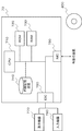
- FIG. 1 is a block diagram showing an example of the configuration of the information processing apparatus according to the first embodiment of the present invention.
- FIG. 2 is a flowchart illustrating an example of the operation of the information processing apparatus.
- FIG. 3 is a diagram illustrating an example of information managed by the physical configuration management unit.
- FIG. 4 is a diagram illustrating an example of information managed by the logical configuration management unit.
- FIG. 5 is a diagram illustrating an example of information managed by the service level definition unit.
- FIG. 6 is a diagram illustrating an example of service levels accumulated by the service level accumulation unit.
- FIG. 7 is a flowchart showing an example of the operation of the service level influence identifying unit.
- FIG. 8 is a diagram illustrating an example of a score corresponding to a service level.
- FIG. 1 is a block diagram showing an example of the configuration of the information processing apparatus according to the first embodiment of the present invention.
- FIG. 2 is a flowchart illustrating an example of the operation of the information processing apparatus.
- FIG. 9 is a diagram illustrating an example of display contents displayed by the information display unit.
- FIG. 10 is a diagram illustrating an example of display contents displayed by the logical information sorting unit.
- FIG. 11 is a block diagram illustrating an example of the configuration of the information processing system according to the first embodiment.
- FIG. 12 is a block diagram illustrating an example of a configuration of an information processing apparatus according to a modification of the first embodiment.
- FIG. 13 is a block diagram illustrating an example of a configuration of an information processing apparatus according to a modification of the first embodiment.
- FIG. 1 is a block diagram illustrating an example of the configuration of the information processing apparatus 5 according to the first embodiment.
- the information processing apparatus 5 includes an influence determination unit 1, a configuration management unit 2, a service level management unit 3, and an information display unit 4.
- the influence determination unit 1 determines the influence on the service level related to the physical configuration based on information managed by the configuration management unit 2 and the service level management unit 3. Furthermore, the influence determination part 1 changes the order of the information displayed on the information display part 4 based on determination.
- the influence determination unit 1 includes a physical configuration selection unit 11, a logical configuration range identification unit 12, a service level influence identification unit 13, and a logical information rearrangement unit 14.
- the physical configuration selection unit 11 selects a physical device that is a target of the influence determination.
- the physical configuration selection unit 11 may select a physical device that is affected by the failure based on the detection result of the failure.
- the physical configuration selection unit 11 may select a physical device that determines an influence in response to an instruction from a terminal operated by a user (not shown).
- the logical configuration range specifying unit 12 specifies the physical device selected by the physical configuration selecting unit 11 and the logical configuration range (for example, logical information, service, and user) related to the physical device.
- each configuration in the logical configuration or the physical configuration and the configuration including the logical or physical connection relation related to each configuration are collectively referred to as “configuration range”.
- the service level influence specifying unit 13 is information (hereinafter collectively referred to as “the level or order in which the service level of the logical configuration cannot be achieved” based on the achievement level of the service level related to the range specified by the logical configuration range specifying unit 12. Identify the score). That is, the service level influence specifying unit 13 specifies a score that is information indicating the degree of influence on the service level.
- the logical information rearrangement unit 14 changes the order of display information in the display of the logical configuration related to the physical device (rearrangement) based on the result (score) specified by the service level influence specifying unit 13.
- the configuration management unit 2 manages information on physical devices to be managed (for example, server devices, network devices, and server devices of virtual machines) and logical resources including the judgment targets of the impact judgment unit 1.
- the configuration management unit 2 includes a physical configuration management unit 21 and a logical configuration management unit 22.
- the physical configuration management unit 21 manages physical devices to be managed (for example, server devices, network devices, and server devices of virtual machines (hereinafter also simply referred to as “virtual machines”)).
- the physical device to be managed by the physical configuration management unit 21 includes a physical device that determines the influence.
- the logical configuration management unit 22 manages logical resources (for example, user information, services, and virtual machines) related to the physical device to be managed.
- logical resources for example, user information, services, and virtual machines
- the service level management unit 3 manages service levels. Therefore, the service level management unit 3 includes a service level storage unit 31 and a service level definition unit 32.
- the service level accumulation unit 31 accumulates service level values calculated based on values aggregated from operating physical devices (for example, virtual machines, server devices, and network devices).
- the service level definition unit 32 manages service level information (for example, target value) maintained by the logically configured service.
- the information display unit 4 displays various information of the information processing device 5. Therefore, the information display unit 4 includes a physical configuration display unit 41 and a logical configuration display unit 42.
- the physical configuration display unit 41 displays the physical configuration. More specifically, the physical configuration display unit 41 displays information on the physical configuration management unit 21 and physical devices (for example, a server device, a network device, and a virtual machine) related to the physical device selected by the physical configuration selection unit 11. indicate.
- physical devices for example, a server device, a network device, and a virtual machine
- the logical configuration display unit 42 displays the logical configuration. More specifically, the logical configuration display unit 42 displays the information of the logical configuration management unit 22, the logical configuration related to the physical information selected by the physical configuration selection unit 11, and the service level.
- the display position and format of information in the information display unit 4 are not particularly limited.
- FIG. 3 is a diagram showing an example of information managed by the physical configuration management unit 21 in this description.
- the physical configuration management unit 21 includes information on a network device (“switch” in FIG. 3), a server device (“Host” in FIG. 3), and a virtual machine (“VM” in FIG. 3). And the mutual connection status.
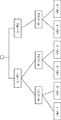
- FIG. 4 is a diagram showing an example of information managed by the logical configuration management unit 22 in this description.
- the logical configuration management unit 22 includes user information (“user” in FIG. 4), a plurality of services managed by the user (“service” in FIG. 4), and device information ( 4 "and the mutual connection information are managed.
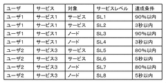
- FIG. 5 is a diagram illustrating an example of service level information managed by the service level definition unit 32.
- the service level information managed by the service level definition unit 32 includes a user, a service, a service target, a target service level, and a service level achievement condition.
- the user and service correspond to the user and service shown in FIG.
- FIG. 6 is a diagram illustrating an example of service levels stored by the service level storage unit 31.
- the information accumulated by the service level accumulation unit 31 includes a service, a service target, a service level, and a service level value indicating the service level.
- FIG. 9 is a diagram illustrating an example of display contents displayed by the information display unit 4.
- the screen 400 displayed by the information display unit 4 illustrated in FIG. 9 includes a physical configuration display part 401 managed by the physical configuration management unit 21 and a logical configuration display part 402 managed by the logical configuration management unit 22. That is, the physical configuration display unit 41 displays the physical configuration information on the display portion 401 in FIG.
- the logical configuration display unit 42 displays logical configuration information on the display portion 402 of FIG.
- the range of information displayed by the information display unit 4 is not particularly limited.
- the information display unit 4 may display all information. Or the information display part 4 may display some information, for example, in order to ensure the visibility of a display.
- the physical configuration display unit 41 displays a part of the information (see FIG. 3) of the physical configuration management unit 21 on the display portion 401.
- the logical configuration display unit 42 displays all the information (see FIG. 4) of the logical configuration management unit 22 on the display portion 402.
- FIG. 2 is a flowchart showing an example of the operation of the information processing apparatus 5.
- the physical configuration selection unit 11 determines a physical device for which influence is to be determined (step A1).
- the physical configuration selection unit 11 selects a physical device based on, for example, operation management monitoring information (detection of a failure) or explicit designation by a user (instruction from a user terminal). select.
- the logical configuration range specifying unit 12 determines the range of the physical configuration related to (affected by) the physical device selected by the physical configuration selection unit 11 (step A2).
- the logical configuration range specifying unit 12 selects a physical device that matches the physical device selected by the physical configuration selection unit 11 from the information managed by the physical configuration management unit 21.
- the logical configuration range specifying unit 12 is based on a unique name such as a host name of a physical device, an IP (Internet Protocol) address, a MAC (Media Access Control) address, or an identifier that can uniquely identify a device.
- a physical device is selected using the comparison process.
- the physical device selected by the logical configuration range specifying unit 12 and the physical device having a lower link of the physical device are affected physical devices. For example, when the logical configuration range specifying unit 12 selects “Host-1” in FIG. 3, “Host-1” and “VM-1” and “VM-2” subordinate to Host-1 are affected. The physical device to receive.
- the logical configuration range specifying unit 12 determines a logical configuration related to the selected physical device located at the lower level (step A3).
- the logical configuration range specifying unit 12 determines the corresponding logical configuration from the information managed by the logical configuration management unit 22 using the information of the lower-level physical device determined in step A2.
- the logical configuration range specifying unit 12 compares, for example, a unique name, an IP address, a MAC address, or an identifier that can uniquely identify a device with similar information in the logical configuration of information managed by the logical configuration management unit 22.
- the unique name is, for example, the host name of the information device managed by the physical configuration management unit 21.
- the logical configuration selected by the logical configuration range specifying unit 12 and the logical configuration higher than the logical configuration are affected ranges. For example, in FIG. 4, when “VM-1” and “VM-2” are lower logical units, “service 1” and “service 2” positioned above them and “user 1” above them are Is the logical configuration range affected.
- the service level influence specifying unit 13 specifies the service level influence range based on the logical configuration range determined by the logical configuration range specifying unit 12. Then, the service level influence specifying unit 13 determines the service level of the affected logical configuration (step A4).
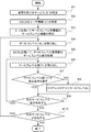
- FIG. 7 is a flowchart showing an example of the operation of the service level influence identifying unit 13 of the present embodiment.
- the service level influence specifying unit 13 specifies the affected services (for example, “service 1” and “service 2” in FIG. 4) (step B1).
- the specified service is referred to as “S”.
- the service level influence specifying unit 13 specifies high-order user information (“user 1” in FIG. 4) of the specified service (step B2).
- the specified user information is referred to as “U”.
- the service level influence specifying unit 13 uses the specified service (S) and user information (U) (as a key) to select a service from the service level information (FIG. 5) managed by the service level defining unit 32.
- the information regarding the service level related to is specified (step B3).
- the information regarding the service level is, for example, a service level, a target, and an achievement condition.
- the service level influence specifying unit 13 extracts any one of the service level information (step B4).
- specification part 13 may take out service level information in order, and may take out at random.
- the service level of the extracted service level information is “SL”. Then, the service level influence specifying unit 13 initializes (for example, sets to “1”) the score of the extracted service level.
- the service level influence specifying unit 13 acquires a service level value from the service level storage unit 31 using the service level (SL) and the service (S) (as a key) (step B5).
- the service level influence specifying unit 13 takes out one service level value when there are a plurality of acquired service level values (step B6).
- the selection method here is also not particularly limited.
- the service level value extracted here is assumed to be “V”.
- the service level influence identifying unit 13 compares the service level value (V) with the achievement condition of the service level information (step B7). That is, the service level influence specifying unit 13 determines whether or not the service level value satisfies the achievement condition.
- the service level influence specifying unit 13 adds the value calculated using the service level calculation method to the score value. (Step B8).
- the service level calculation method is referred to as “f (service level)”.
- f service level
- f (service level) is not limited to this, and may be set, for example, for each service level and each service type (for example, time or achievement rate).
- f (service level) is not particularly limited.
- f (service level) may be a value obtained by subtracting the achievement level of service level from 1.
- a predetermined evaluation function may be used for f (service level).
- FIG. 8 is a diagram showing an example of a score corresponding to the service level.
- the score of service level SL1 of service 1 in FIG. 8 is “10”.
- the score is added when the service level value does not satisfy the achievement condition. For this reason, the service level that does not satisfy the achievement condition has a higher score. That is, the service level SL1 having a score of “10” has more unsatisfactory achievement conditions than the service level SL3 having a score of “1”.
- the score is information indicating the degree of influence on the service level.
- the service level influence identifying unit 13 determines whether there is an undetermined service level value (step B9).
- step B9 If there is a service level value that has not been determined (YES in step B9), the service level influence identifying unit 13 repeats the processing from step B6 on the next service level value.
- the service level influence specifying unit 13 determines whether or not service level information (service level) that has not been determined remains (step B10).
- step B10 If there is a service level that has not been determined (YES in step B10), the service level influence identifying unit 13 repeats the processing from step B4 for the next service level.
- step B10 If all service levels have been determined (NO in step B10), the service level influence identifying unit 13 ends the process.
- the service level influence specifying unit 13 repeats the process shown in FIG. 7 for all affected services.
- the logical information rearrangement unit 14 rearranges the services in descending order of the score values calculated by the service level influence identification unit 13 and displays them on the logical configuration display unit 42 (step A5). ).
- the logical information rearrangement unit 14 displays the physical device specified by the logical configuration range specifying unit 12 on the physical configuration display unit 41 in accordance with the display change of the logical configuration display unit 42. That is, the logical information rearrangement unit 14 changes the display of the information display unit 4 based on the score.
- FIG. 10 is a diagram illustrating an example of display contents displayed by the logical information sorting unit 14 after processing.
- FIG. 10 is an example of a display when the physical configuration selection unit 11 selects “Host-1” as a physical device in which many service level violations have occurred.
- “Host-1” is indicated by a broken line.
- VM-1 The subordinates of “Host-1” are “VM-1” and “VM-2”. It is assumed that “VM-2” has more violations than “VM-1”. “VM-2” is related to the logical configuration “service 2”. Therefore, the service 2 related to “VM-2” in which the most violations occur has the highest score.
- VM-1 is related to the logical configuration “service 1”. Then, it is assumed that “VM-1” has a violation after “VM-2”. Therefore, service 1 related to “VM-1” has the next highest score after “service 2”. That is, the service (service 2 and service 1) in which many service level violations have occurred has a higher score than the other services. Therefore, in the display portion 402 of FIG. 10, “service 2” and “service 1” (and related “user 1”) are displayed on the upper side, which is easier to visually recognize than other services.
- the information processing apparatus 5 can display a service in which violations frequently occur on the upper side.
- a violation is an example of an IT system failure. That is, the information processing device 5 displays the service affected by the failure of the IT system on the upper side of the logical configuration display unit 42 of the information display unit 4. An operator who confirms the information display unit 4 can easily determine the affected service by confirming the display on the upper side of the display portion 402.
- the information processing device 5 does not have to limit the display based on the score to the display above the display portion 402.
- the information processing apparatus 5 may adopt another display method based on the magnitude of the score.
- the information processing device 5 may change the size of characters or the thickness of characters based on the score.
- the information processing apparatus 5 of the present embodiment can determine the degree of influence on the service of the physical device. Furthermore, the information processing apparatus 5 can display the affected services in the order based on the score, which is information indicating the degree of influence of the service level.
- the information processing apparatus 5 can display services in accordance with the degree of influence of IT system failures on services. That is, the information processing apparatus 5 of the present embodiment can obtain an effect of displaying a service so that the degree of influence on the service can be easily determined.
- the physical configuration selection unit 11 of the information processing apparatus 5 selects a physical device for determining the influence. Then, the logical configuration range specifying unit 12 specifies the logical configuration range related to the physical device. And the service level influence specific
- the information processing apparatus 5 can specify the degree of influence of a physical device as a score.
- the logical information rearrangement unit 14 of this embodiment rearranges the information of the logical configuration to be displayed based on the score. Therefore, the information processing apparatus 5 according to the present embodiment can display the logical configuration (for example, service) in the order based on the service level achievement status.
- the configuration of the information processing apparatus 5 is not limited to the above description.
- the information processing apparatus 5 may divide each configuration into a plurality of configurations.
- the information processing apparatus 5 may divide the logical information rearrangement unit 14 into a function for rearranging the logical configuration and a function for changing the display of the corresponding physical configuration. Further, the information processing apparatus 5 may realize the physical configuration management unit 21 and the logical configuration management unit 22 of the configuration management unit 2 using different storage devices.
- the information processing device 5 may be a separate device that connects at least a part of the impact determination unit 1, the configuration management unit 2, the service level management unit 3, and the information display unit 4 via a network or a bus. good.
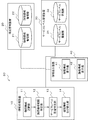
- FIG. 11 is a block diagram showing an example of the configuration of the information processing system 50 according to the present embodiment. 11, the same components as those in FIG. 1 are denoted by the same reference numerals, and detailed description thereof is omitted.
- the information processing system 50 includes an information processing device 10 corresponding to the influence determination unit 1, a configuration management device 20 corresponding to the configuration management unit 2, a service level management device 30 corresponding to the service level management unit 3, and an information display unit. 4 and the information display device 40 corresponding to 4. Each device is connected via a network to realize the function of each unit of the information processing device 5.
- FIG. 12 is a block diagram illustrating an example of the configuration of the information processing apparatus 10.
- the information processing apparatus 10 shown in FIG. 12 includes a physical configuration selection unit 11, a logical configuration range specification unit 12, a service level influence specification unit 13, and a logical information rearrangement unit 14.
- the physical configuration selection unit 11 of the information processing device 10 can select a physical device for determining the influence, similarly to the physical configuration selection unit 11 of the information processing device 5.
- the logical configuration range specifying unit 12 can specify the logical configuration range related to the physical device selected by the physical configuration selecting unit 11 using the configuration management device 20.
- the service level influence specifying unit 13 can use the service level management device 30 to specify the score based on the achievement level of the service level related to the logical configuration range.
- the information processing apparatus 10 can obtain the effect of specifying the degree of influence of the physical device as a score, like the information processing apparatus 5.
- the logical information rearrangement unit 14 of the information processing device 10 rearranges the information on the logical configuration displayed on the information display device 40 based on the score specified by the service level influence specifying unit 13. That is, the information processing apparatus 10 can rearrange the logical configurations (for example, services) in the order based on the service level achievement status similarly to the information processing apparatus 5.
- the information processing apparatus 10 can realize the same function as the information processing apparatus 5.
- the information processing apparatus 10 is the minimum configuration of the present embodiment.
- the information processing apparatuses 5 and 10 may have a plurality of configurations as one configuration.
- each of the information processing devices 5 and 10 may be realized as a computer device including a CPU (Central Processing Unit), a ROM (Read Only Memory), and a RAM (Random Access Memory).
- the information processing apparatus 5 may be realized as a computer apparatus including an input / output connection circuit (IOC: Input / Output Circuit) and a network interface circuit (NIC: Network Interface Circuit) in addition to these configurations.
- IOC Input / Output Circuit
- NIC Network Interface Circuit
- FIG. 13 is a block diagram illustrating an example of the configuration of an information processing apparatus 70 that is a modification of the information processing apparatus 5 of the present embodiment.
- the information processing apparatus 70 includes a CPU 710, a ROM 720, a RAM 730, an internal storage device 740, an IOC 750, and a NIC 780, and constitutes a computer.
- the CPU 710 reads a program from ROM 720.
- the CPU 710 controls the RAM 730, the internal storage device 740, the IOC 750, and the NIC 780 based on the read program. Then, the CPU 710 controls these configurations and realizes the functions as the influence determination unit 1, the configuration management unit 2, the service level management unit 3, and the information display unit 4 illustrated in FIG. 1.
- the CPU 710 may use the RAM 730 as a temporary storage of a program when realizing each function.
- the CPU 710 may read a program included in the storage medium 800 that stores the program so as to be readable by a computer using a storage medium reading device (not shown). Alternatively, the CPU 710 may receive a program from an external device (not shown) via the NIC 780.
- ROM 720 stores a program executed by CPU 710 and fixed data.
- the ROM 720 is, for example, a P-ROM (Programmable-ROM) or a flash ROM.
- the RAM 730 temporarily stores programs and data executed by the CPU 710.
- the RAM 730 is, for example, a D-RAM (Dynamic-RAM).
- the internal storage device 740 stores data and programs that the information processing device 70 stores for a long time. Further, the internal storage device 740 may operate as a temporary storage device for the CPU 710. Further, the internal storage device 740 may operate as the configuration management unit 2 or the service level management unit 3.
- the internal storage device 740 is, for example, a hard disk device, a magneto-optical disk device, an SSD (Solid State Drive), or a disk array device.
- the IOC 750 mediates data between the CPU 710, the input device 760, and the display device 770.
- the IOC 750 is, for example, an IO interface card.
- the input device 760 is a device that receives an input instruction from an operator of the information processing apparatus 70.
- the input device 760 is, for example, a keyboard, a mouse, or a touch panel.
- the display device 770 is a device that displays information to the operator of the information processing apparatus 70.
- the display device 770 is a liquid crystal display, for example.
- the display device 770 may operate as the information display unit 4.
- the NIC 780 relays data exchange with an external device via a network.
- the NIC 780 is, for example, a LAN (Local Area Network) card.
- the information processing apparatus 70 may use an external device (not shown) connected via the NIC 780 as the information display unit 4.
- the information processing apparatus 70 configured as described above can obtain the same effects as the information processing apparatus 5.
- (Appendix 1) Physical configuration selection means for selecting a physical device to determine the influence;
- Logical configuration range specifying means for specifying a logical configuration range related to the physical device;
- a service level impact identifying means for identifying a score that is,
- An information processing apparatus comprising: logical information rearranging means for rearranging the order of display information of the logical configuration based on the score.
- Appendix 2 Physical configuration management means for managing information on a physical device to be managed including the physical device selected by the physical configuration selection means;
- the information processing apparatus according to appendix 1, further comprising: a configuration management unit that includes logical configuration management unit that manages logical resource information including the range of the logical configuration specified by the logical configuration range specifying unit.
- Service level defining means for managing service level information maintained by the service of the logical configuration referenced by the service level influence identifying means;
- the information processing apparatus according to appendix 1 or appendix 2 including service level management means including service level accumulation means for accumulating service level values relating to physical devices referred to by the service level influence identifying means.
- the present invention can be applied to a system that identifies a service or a user that affects an influence when a problem such as a failure occurs in a device and takes measures based on the degree of service level violation.
- the present invention can also be applied to a monitoring device that confirms a service level of a user or a service that has an influence when a device selected on a GUI (Graphical User Interface) is specified.
- GUI Graphic User Interface
Landscapes
- Engineering & Computer Science (AREA)
- Computer Networks & Wireless Communication (AREA)
- Signal Processing (AREA)
- Theoretical Computer Science (AREA)
- Quality & Reliability (AREA)
- Physics & Mathematics (AREA)
- General Engineering & Computer Science (AREA)
- General Physics & Mathematics (AREA)
- Human Computer Interaction (AREA)
- Probability & Statistics with Applications (AREA)
- Automation & Control Theory (AREA)
- Debugging And Monitoring (AREA)
- Information Transfer Between Computers (AREA)
Abstract
Description
まず、本発明における第1の実施形態の情報処理装置5の構成について説明する。
なお、情報処理装置5の構成は、これまでの説明に限らない。情報処理装置5は、各構成を複数の構成に分けても良い。
影響を判定する物理装置を選択する物理構成選択手段と、
前記物理装置に関連する論理構成の範囲を特定する論理構成範囲特定手段と、
前記論理構成のサービスが維持するサービスレベルと前記物理装置に関するサービスレベル値を基にサービスレベルの達成状況を判定し、前記達成状況を基に前記論理構成のサービスレベルに与える影響の程度を示す情報であるスコアを特定するサービスレベル影響特定手段と、
前記スコアを基に前記論理構成の表示情報の順番を並び替える論理情報並び替え手段と
を含む情報処理装置。
前記物理構成選択手段が選択する前記物理装置を含む管理対象の物理装置の情報を管理する物理構成管理手段と、
前記論理構成範囲特定手段が特定する前記論理構成の範囲を含む論理的な資源の情報を管理する論理構成管理手段と
を含む構成管理手段
を含む付記1に記載の情報処理装置。
前記サービスレベル影響特定手段が参照する前記論理構成のサービスが維持するサービスレベル情報を管理するサービスレベル定義手段と、
前記サービスレベル影響特定手段が参照する物理装置に関するサービスレベル値を蓄積するサービスレベル蓄積手段と
を含むサービスレベル管理手段と
を含む付記1又は付記2に記載の情報処理装置。
前記物理構成を表示する物理構成表示手段と、
前記論理構成を表示する論理構成表示手段と
を含む情報表示手段
を含む付記1乃至付記3のいずれか1項に記載の情報処理装置。
影響を判定する物理装置を選択し、
前記物理装置に関連する論理構成の範囲を特定し、
前記論理構成のサービスが維持するサービスレベルと前記物理装置に関するサービスレベル値を基にサービスレベルの達成状況を判定し、前記達成状況を基に前記論理構成のサービスレベルに与える影響の程度を示す情報であるスコアを特定し、
前記スコアを基に前記論理構成の表示情報の順番を並び替える
影響判定方法。
影響を判定する物理装置を選択する処理と、
前記物理装置に関連する論理構成の範囲を特定する処理と、
前記論理構成のサービスが維持するサービスレベルと前記物理装置に関するサービスレベル値を基にサービスレベルの達成状況を判定し、前記達成状況を基に前記論理構成のサービスレベルに与える影響の程度を示す情報であるスコアを特定する処理と、
前記スコアを基に前記論理構成の表示情報の順番を並び替える処理と
をコンピュータに実行させるプログラムを記録したコンピュータ読み取り可能な記録媒体。
2 構成管理部
3 サービスレベル管理部
4 情報表示部
5 情報処理装置
10 情報処理装置
11 物理構成選択部
12 論理構成範囲特定部
13 サービスレベル影響特定部
14 論理情報並び替え部
20 構成管理装置
21 物理構成管理部
22 論理構成管理部
30 サービスレベル管理装置
31 サービスレベル蓄積部
32 サービスレベル定義部
40 情報表示装置
41 物理構成表示部
42 論理構成表示部
50 情報処理システム
70 情報処理装置
400 画面
401 表示部分
402 表示部分
710 CPU
720 ROM
730 RAM
740 内部記憶装置
750 IOC
760 入力機器
770 表示機器
780 NIC
800 記憶媒体
Claims (6)
- 影響を判定する物理装置を選択する物理構成選択手段と、
前記物理装置に関連する論理構成の範囲を特定する論理構成範囲特定手段と、
前記論理構成のサービスが維持するサービスレベルと前記物理装置に関するサービスレベル値を基にサービスレベルの達成状況を判定し、前記達成状況を基に前記論理構成のサービスレベルに与える影響の程度を示す情報であるスコアを特定するサービスレベル影響特定手段と、
前記スコアを基に前記論理構成の表示情報の順番を並び替える論理情報並び替え手段と
を含む情報処理装置。 - 前記物理構成選択手段が選択する前記物理装置を含む管理対象の物理装置の情報を管理する物理構成管理手段と、
前記論理構成範囲特定手段が特定する前記論理構成の範囲を含む論理的な資源の情報を管理する論理構成管理手段と
を含む構成管理手段
を含む請求項1に記載の情報処理装置。 - 前記サービスレベル影響特定手段が参照する前記論理構成のサービスが維持するサービスレベル情報を管理するサービスレベル定義手段と、
前記サービスレベル影響特定手段が参照する物理装置に関するサービスレベル値を蓄積するサービスレベル蓄積手段と
を含むサービスレベル管理手段と
を含む請求項1又は請求項2に記載の情報処理装置。 - 前記物理構成を表示する物理構成表示手段と、
前記論理構成を表示する論理構成表示手段と
を含む情報表示手段
を含む請求項1乃至請求項3のいずれか1項に記載の情報処理装置。 - 影響を判定する物理装置を選択し、
前記物理装置に関連する論理構成の範囲を特定し、
前記論理構成のサービスが維持するサービスレベルと前記物理装置に関するサービスレベル値を基にサービスレベルの達成状況を判定し、前記達成状況を基に前記論理構成のサービスレベルに与える影響の程度を示す情報であるスコアを特定し、
前記スコアを基に前記論理構成の表示情報の順番を並び替える
影響判定方法。 - 影響を判定する物理装置を選択する処理と、
前記物理装置に関連する論理構成の範囲を特定する処理と、
前記論理構成のサービスが維持するサービスレベルと前記物理装置に関するサービスレベル値を基にサービスレベルの達成状況を判定し、前記達成状況を基に前記論理構成のサービスレベルに与える影響の程度を示す情報であるスコアを特定する処理と、
前記スコアを基に前記論理構成の表示情報の順番を並び替える処理と
をコンピュータに実行させるプログラムを記録したコンピュータ読み取り可能な記録媒体。
Priority Applications (3)
| Application Number | Priority Date | Filing Date | Title |
|---|---|---|---|
| JP2014558486A JP6237649B2 (ja) | 2013-01-23 | 2014-01-15 | 情報処理装置及び影響判定方法 |
| US14/759,988 US20150350034A1 (en) | 2013-01-23 | 2014-01-15 | Information processing device, influence determination method and medium |
| CN201480005868.9A CN104969195A (zh) | 2013-01-23 | 2014-01-15 | 信息处理设备和影响确定方法 |
Applications Claiming Priority (2)
| Application Number | Priority Date | Filing Date | Title |
|---|---|---|---|
| JP2013-010178 | 2013-01-23 | ||
| JP2013010178 | 2013-01-23 |
Publications (1)
| Publication Number | Publication Date |
|---|---|
| WO2014115504A1 true WO2014115504A1 (ja) | 2014-07-31 |
Family
ID=51227301
Family Applications (1)
| Application Number | Title | Priority Date | Filing Date |
|---|---|---|---|
| PCT/JP2014/000145 Ceased WO2014115504A1 (ja) | 2013-01-23 | 2014-01-15 | 情報処理装置及び影響判定方法 |
Country Status (4)
| Country | Link |
|---|---|
| US (1) | US20150350034A1 (ja) |
| JP (1) | JP6237649B2 (ja) |
| CN (1) | CN104969195A (ja) |
| WO (1) | WO2014115504A1 (ja) |
Cited By (1)
| Publication number | Priority date | Publication date | Assignee | Title |
|---|---|---|---|---|
| JP2015215670A (ja) * | 2014-05-08 | 2015-12-03 | 富士通株式会社 | 資源表示プログラム,情報処理装置および資源表示方法 |
Families Citing this family (1)
| Publication number | Priority date | Publication date | Assignee | Title |
|---|---|---|---|---|
| WO2021107904A1 (en) * | 2019-11-28 | 2021-06-03 | Turkcell Teknoloji Arastirma Ve Gelistirme Anonim Sirketi | System for creating a service model |
Citations (4)
| Publication number | Priority date | Publication date | Assignee | Title |
|---|---|---|---|---|
| WO2009144822A1 (ja) * | 2008-05-30 | 2009-12-03 | 富士通株式会社 | 装置構成情報管理プログラム、装置構成情報管理装置及び装置構成情報管理方法 |
| JP2011180805A (ja) * | 2010-03-01 | 2011-09-15 | Nec Corp | 運用管理装置、運用管理方法、運用管理プログラム |
| JP2012038028A (ja) * | 2010-08-05 | 2012-02-23 | Nomura Research Institute Ltd | インシデント管理システム、障害影響範囲可視化方法 |
| WO2012169020A1 (ja) * | 2011-06-08 | 2012-12-13 | 株式会社日立製作所 | インパクト分析方法、インパクト分析装置及び記憶媒体 |
Family Cites Families (9)
| Publication number | Priority date | Publication date | Assignee | Title |
|---|---|---|---|---|
| CN1770117A (zh) * | 2004-11-02 | 2006-05-10 | 华为技术有限公司 | 一种故障选择的方法及装置 |
| JP2007041828A (ja) * | 2005-08-03 | 2007-02-15 | Hitachi Ltd | Sla達成状況判定方法 |
| CN101808351B (zh) * | 2009-02-17 | 2014-06-18 | 中兴通讯股份有限公司南京分公司 | 业务影响分析方法和系统 |
| JP2010205126A (ja) * | 2009-03-05 | 2010-09-16 | Nec Corp | サービス構成管理装置およびサービス構成管理方法並びにプログラム |
| JP2011113122A (ja) * | 2009-11-24 | 2011-06-09 | Mitsubishi Electric Corp | 障害影響分析装置及び業務システム及び障害影響分析方法 |
| JP2013178592A (ja) * | 2010-05-06 | 2013-09-09 | Hitachi Ltd | 情報処理システムの運用管理装置および運用管理方法 |
| US9122602B1 (en) * | 2011-08-31 | 2015-09-01 | Amazon Technologies, Inc. | Root cause detection service |
| US20130097183A1 (en) * | 2011-10-14 | 2013-04-18 | Zenoss, Inc. | Method and apparatus for analyzing a root cause of a service impact in a virtualized environment |
| CN102695185B (zh) * | 2012-05-30 | 2015-05-06 | 北京神州泰岳软件股份有限公司 | 监控系统业务影响分析方法 |
-
2014
- 2014-01-15 JP JP2014558486A patent/JP6237649B2/ja active Active
- 2014-01-15 CN CN201480005868.9A patent/CN104969195A/zh active Pending
- 2014-01-15 WO PCT/JP2014/000145 patent/WO2014115504A1/ja not_active Ceased
- 2014-01-15 US US14/759,988 patent/US20150350034A1/en not_active Abandoned
Patent Citations (4)
| Publication number | Priority date | Publication date | Assignee | Title |
|---|---|---|---|---|
| WO2009144822A1 (ja) * | 2008-05-30 | 2009-12-03 | 富士通株式会社 | 装置構成情報管理プログラム、装置構成情報管理装置及び装置構成情報管理方法 |
| JP2011180805A (ja) * | 2010-03-01 | 2011-09-15 | Nec Corp | 運用管理装置、運用管理方法、運用管理プログラム |
| JP2012038028A (ja) * | 2010-08-05 | 2012-02-23 | Nomura Research Institute Ltd | インシデント管理システム、障害影響範囲可視化方法 |
| WO2012169020A1 (ja) * | 2011-06-08 | 2012-12-13 | 株式会社日立製作所 | インパクト分析方法、インパクト分析装置及び記憶媒体 |
Cited By (1)
| Publication number | Priority date | Publication date | Assignee | Title |
|---|---|---|---|---|
| JP2015215670A (ja) * | 2014-05-08 | 2015-12-03 | 富士通株式会社 | 資源表示プログラム,情報処理装置および資源表示方法 |
Also Published As
| Publication number | Publication date |
|---|---|
| JPWO2014115504A1 (ja) | 2017-01-26 |
| JP6237649B2 (ja) | 2017-11-29 |
| CN104969195A (zh) | 2015-10-07 |
| US20150350034A1 (en) | 2015-12-03 |
Similar Documents
| Publication | Publication Date | Title |
|---|---|---|
| JP5674248B2 (ja) | 監視状況表示装置、監視状況表示方法および監視状況表示プログラム | |
| US12149399B2 (en) | Techniques and interfaces for troubleshooting datacenter networks | |
| US10417195B2 (en) | Management system for managing information system | |
| JP5385459B2 (ja) | 管理システム及び計算機システムの管理方法 | |
| JP6190468B2 (ja) | 管理システム、プラン生成方法、およびプラン生成プログラム | |
| JP4811830B1 (ja) | コンピュータリソース制御システム | |
| US20120005609A1 (en) | Management system and management system control method | |
| US20250110818A1 (en) | Computing cluster health reporting engine | |
| JP6482984B2 (ja) | クラウド管理方法及びクラウド管理システム | |
| WO2013124947A1 (ja) | 情報システム管理装置及び情報システム管理方法及びプログラム | |
| JPWO2017110720A1 (ja) | ログ分析システム、ログ分析方法及びプログラム | |
| JP2021061490A (ja) | 表示情報処理装置、表示情報処理方法および表示情報処理プログラム | |
| JP6237649B2 (ja) | 情報処理装置及び影響判定方法 | |
| JP2010009411A (ja) | 仮想化環境運用支援システム及び仮想環境運用支援プログラム | |
| US20150100677A1 (en) | Managing server system, and control method for the same | |
| WO2020195230A1 (ja) | 分析システム、方法およびプログラム | |
| JP6269004B2 (ja) | 監視支援プログラム、監視支援方法および監視支援装置 | |
| US20250008027A1 (en) | Information provision system and information provision method | |
| JP7027912B2 (ja) | 順序制御プログラム、順序制御方法、及び情報処理装置 | |
| US20200394091A1 (en) | Failure analysis support system, failure analysis support method, and computer readable recording medium | |
| JP2006344091A (ja) | システム再構成自動化装置 | |
| JP5384566B2 (ja) | フロントエンドサーバ、インタプリタ型プログラム及び方法 | |
| JP2012089109A (ja) | コンピュータリソース制御システム | |
| JP2023086395A (ja) | 管理プログラム、装置、及び方法 | |
| WO2018131147A1 (ja) | 管理システム、管理装置、および管理方法 |
Legal Events
| Date | Code | Title | Description |
|---|---|---|---|
| 121 | Ep: the epo has been informed by wipo that ep was designated in this application |
Ref document number: 14743154 Country of ref document: EP Kind code of ref document: A1 |
|
| ENP | Entry into the national phase |
Ref document number: 2014558486 Country of ref document: JP Kind code of ref document: A |
|
| WWE | Wipo information: entry into national phase |
Ref document number: 14759988 Country of ref document: US |
|
| NENP | Non-entry into the national phase |
Ref country code: DE |
|
| 122 | Ep: pct application non-entry in european phase |
Ref document number: 14743154 Country of ref document: EP Kind code of ref document: A1 |