WO2014115263A1 - 位置決め制御システム - Google Patents
位置決め制御システム Download PDFInfo
- Publication number
- WO2014115263A1 WO2014115263A1 PCT/JP2013/051288 JP2013051288W WO2014115263A1 WO 2014115263 A1 WO2014115263 A1 WO 2014115263A1 JP 2013051288 W JP2013051288 W JP 2013051288W WO 2014115263 A1 WO2014115263 A1 WO 2014115263A1
- Authority
- WO
- WIPO (PCT)
- Prior art keywords
- control system
- control
- positioning control
- positioning
- axis direction
- Prior art date
- Legal status (The legal status is an assumption and is not a legal conclusion. Google has not performed a legal analysis and makes no representation as to the accuracy of the status listed.)
- Ceased
Links
Images







Classifications
-
- G—PHYSICS
- G05—CONTROLLING; REGULATING
- G05B—CONTROL OR REGULATING SYSTEMS IN GENERAL; FUNCTIONAL ELEMENTS OF SUCH SYSTEMS; MONITORING OR TESTING ARRANGEMENTS FOR SUCH SYSTEMS OR ELEMENTS
- G05B19/00—Program-control systems
- G05B19/02—Program-control systems electric
- G05B19/18—Numerical control [NC], i.e. automatically operating machines, in particular machine tools, e.g. in a manufacturing environment, so as to execute positioning, movement or co-ordinated operations by means of program data in numerical form
- G05B19/404—Numerical control [NC], i.e. automatically operating machines, in particular machine tools, e.g. in a manufacturing environment, so as to execute positioning, movement or co-ordinated operations by means of program data in numerical form characterised by control arrangements for compensation, e.g. for backlash, overshoot, tool offset, tool wear, temperature, machine construction errors, load, inertia
-
- G—PHYSICS
- G05—CONTROLLING; REGULATING
- G05B—CONTROL OR REGULATING SYSTEMS IN GENERAL; FUNCTIONAL ELEMENTS OF SUCH SYSTEMS; MONITORING OR TESTING ARRANGEMENTS FOR SUCH SYSTEMS OR ELEMENTS
- G05B19/00—Program-control systems
-
- G—PHYSICS
- G05—CONTROLLING; REGULATING
- G05B—CONTROL OR REGULATING SYSTEMS IN GENERAL; FUNCTIONAL ELEMENTS OF SUCH SYSTEMS; MONITORING OR TESTING ARRANGEMENTS FOR SUCH SYSTEMS OR ELEMENTS
- G05B2219/00—Program-control systems
- G05B2219/30—Nc systems
- G05B2219/42—Servomotor, servo controller kind till VSS
- G05B2219/42249—Relative positioning
-
- G—PHYSICS
- G05—CONTROLLING; REGULATING
- G05B—CONTROL OR REGULATING SYSTEMS IN GENERAL; FUNCTIONAL ELEMENTS OF SUCH SYSTEMS; MONITORING OR TESTING ARRANGEMENTS FOR SUCH SYSTEMS OR ELEMENTS
- G05B2219/00—Program-control systems
- G05B2219/30—Nc systems
- G05B2219/49—Nc machine tool, till multiple
- G05B2219/49176—Compensation of vibration of machine base due to slide movement
-
- H—ELECTRICITY
- H10—SEMICONDUCTOR DEVICES; ELECTRIC SOLID-STATE DEVICES NOT OTHERWISE PROVIDED FOR
- H10P—GENERIC PROCESSES OR APPARATUS FOR THE MANUFACTURE OR TREATMENT OF DEVICES COVERED BY CLASS H10
- H10P72/00—Handling or holding of wafers, substrates or devices during manufacture or treatment thereof
- H10P72/50—Handling or holding of wafers, substrates or devices during manufacture or treatment thereof for positioning, orientation or alignment
Definitions
- the present invention relates to a positioning control system for controlling the position of a moving body.
- the positioning accuracy of the moving bodies constituting the device is a major factor that determines the quality of processed products and mechatronic products.
- a positioning control system that controls the positioning of a moving body is recognized as an important mechanism element that determines the quality of a product. Technological development is progressing to improve positioning accuracy.
- a servo system is formed by a host controller, a servo amplifier, and a servo motor.
- a servo amplifier to which the operation command for positioning control of the device is input, in the servo system that drives the servo motor connected to the load device with variable speed by the drive current based on the position / speed adjustment calculation result for positioning control, A servo system is disclosed in which a load device continuously performs reciprocating motions a plurality of times in a servo amplifier even when no operation command is issued.
- Factors affecting the accuracy of the positioning control system include, for example, changes in the position of the center of gravity and changes in rigidity of the configuration including the moving body, balance between thrust and inertial force, machine differences associated with component processing accuracy and assembly accuracy, etc. There is a tendency that the influence becomes remarkable as the movable range of the moving body becomes wider. In addition, deterioration of lubricants and adhesives used for components such as linear guides, wear of sliding / connecting parts, secular changes such as deformation and creep, or floor rigidity, ground vibration, vibration from peripheral devices The installation environment of the positioning device such as propagation also affects the characteristic variation of the controlled object. Therefore, it is important to realize uniform and accurate mechanism characteristics over the entire operating range of the moving body and to suppress fluctuations in the characteristics of the controlled object.
- control parameter is determined based on the characteristics and response at the position of the control target at the time of adjustment execution, it is not possible to perform appropriate adjustment considering the position dependency of the control target. Therefore, it is difficult to maintain robustness with respect to position dependence over the entire movable range.
- the present invention has been made in view of the above, and an object of the present invention is to provide a positioning control system that is highly robust with respect to the position dependency of the control target in the entire movable range and the machine difference of each device.
- the present invention measures a moving device that moves a moving object, a position detecting device that detects the position of the moving object, and control characteristics of a control system of the moving device at a plurality of positions.
- a measurement device an adjustment value calculation unit for calculating an adjustment value for adjusting a control parameter of a control system of the mobile device based on the plurality of measurement results obtained by the measurement device, and a position detection device. Based on the detection result and the control parameter, the moving object is controlled to move to a predetermined target position, and the control parameter is adjusted based on the adjustment value calculated by the adjustment value calculation unit.
- a control parameter adjustment unit is provided.
- the present invention it is possible to provide a positioning control system having high robustness with respect to the position dependency of the controlled object in the entire movable range and the machine difference of each device.
- FIG. 10 is a diagram corresponding to the characteristics of the controlled object shown in FIG. 9 and showing open loop characteristics when the notch filter is automatically adjusted. It is a figure which shows the sensitivity function corresponding to the open loop characteristic shown in FIG. It is a figure which shows schematically the whole structure of the component mounting apparatus which concerns on 2nd Embodiment. It is a figure which shows schematically the whole structure of the semiconductor manufacturing / inspection apparatus which concerns on 3rd Embodiment. It is a figure which shows roughly the whole structure of the printed circuit board processing apparatus which concerns on 4th Embodiment.
- FIG. 1 is a diagram schematically showing an overall configuration of a positioning control system according to the present embodiment.
- the X axis is set in the horizontal direction and the Y axis is set in the vertical direction.
- the positioning control system includes a base table 100 serving as a base of the positioning control system, a top table 110 as a movement target, an X-axis direction driving mechanism 120 that is a moving device that moves the top table 110, and a Y-axis direction.
- the driving mechanism 130 and a control device 140 that controls the operation of the entire positioning control system including them are schematically configured.
- the positioning control system shown in the present embodiment moves the top table 110 by operating the X-axis direction driving mechanism 120 and the Y-axis direction driving mechanism 130 under the control of the control device 140, and positioning the top table 110 with respect to the base table 100. Is to do.
- the Y-axis direction drive mechanism 130 includes a Y-axis direction linear guide 131, a Y-axis direction drive motor stator 132, and a Y-axis direction linear scale 133 that are arranged on the base table 100 along the Y-axis direction. Yes.
- a slide unit (not shown) is attached to the Y-axis direction linear guide 131, thereby guiding the movement of the Y table 126 of the X-axis direction drive mechanism 120 in the Y-axis direction.
- the Y table 126 can be driven along the Y axis direction linear guide 131 by driving the Y axis direction motor movable element 124 provided on the Y table 126 with respect to the Y axis direction motor stator 132. .
- the Y-axis direction linear scale 133 and the Y scale head 125 constitute a part of a position detection device that detects the position of the top table 110 that is a movement target.
- the X-axis direction drive mechanism 120 has an X-axis direction linear guide 121, an X-axis direction drive motor stator 122, and an X-axis direction linear scale 123 arranged on the Y table 126 along the X-axis direction. Yes.
- a slide unit (not shown) is attached to the X-axis direction linear guide 121, thereby guiding the movement of the top table 110 in the X-axis direction. Further, the top table 110 can be driven along the X-axis direction linear guide 121 by driving the X-axis direction motor movable element 111 provided on the top table 110 with respect to the X-axis direction motor stator 122. .
- the position (coordinates) of the top table 110 in the X-axis direction can be detected.
- the X-axis direction linear scale 123 and the X scale head 112 constitute a part of a position detection device that detects the position of the top table 110 that is a movement target.
- the mass configured to be driven in the Y-axis direction by the Y-axis direction drive motor movable element 124 includes the Y table 126, the X-axis direction linear guide 123, the X-axis direction motor stator 122, the top table 110, and the like. Since the position of the center of gravity of the movable mass in the Y-axis direction varies greatly depending on the position of the top table 110, the characteristics of the controlled object change such that the resonance frequency and the magnitude of the resonance peak change as seen from the control system in the Y-axis direction.
- the load varies depending on the position of the top table 110 due to the mounting accuracy and lubrication state of the X-axis direction and Y-axis direction linear guides 121 and 131, the deflection of the Y table 126, and the like.
- the control device 140 includes a display device 141 that displays various information and setting screens, an input device 142 that inputs various information and setting values, a storage unit 143 that stores various information and setting values, and a control system in the positioning control system.
- a control system in the positioning control system.
- the adjustment value calculation unit 145 for calculating the adjustment value, the detection result of the position detection device, and the control parameter
- the top table 110 that is the movement target is controlled to move to a predetermined target position, and the adjustment value
- a control parameter adjustment unit 146 that adjusts the control parameter based on the adjustment value calculated by the calculation unit 145.
- FIG. 2 is a functional block diagram showing a control system of the positioning control system in the present embodiment.
- the control system in one axial direction for example, the X-axis direction
- the same configuration is applied to other axial directions (for example, the Y-axis direction).
- the command generation unit 150 outputs the movement of the top table 110 to the target position as a position command, and movements such as a target movement amount, speed, acceleration, etc. that are preset and stored in the storage unit 143.
- a position command is generated and output using parameters.
- the subtractor 151 includes a Y scale head 125 in conjunction with the current position (in other words, the Y-axis direction motor movable element 124 controlled by the position command) which is the position command output from the command generation unit 150 and the output 156a of the control target 156. And the difference from the position in the Y-axis direction detected in step S3) is output to the signal processing unit 152.
- the signal processing unit 152 includes a controller 153 and a filter 154, and calculates and outputs an operation amount for the control target 156.
- the controller 153 of the signal processing unit 152 can be realized using, for example, a PID controller.
- the transfer function Gc of the controller 153 in the present embodiment is expressed by the following equation 1 where s is a Laplace operator, Kp is a proportional gain, Ki is an integral gain, and Kd is a differential gain.
- the filter 154 of the signal processing unit 152 can be realized using, for example, a notch filter that suppresses vibration at a resonance frequency.
- the transfer function Gf of the filter 154 in the present embodiment is expressed by the following expression 2 where ⁇ c is the resonance frequency and ⁇ is the parameter that determines the width of the notch.
- the open loop characteristic is suitable for evaluating the stability of the control system
- the sensitivity function is suitable for evaluating the disturbance suppression characteristic
- control parameter adjustment unit 146 adjusts the parameter of the filter 154 (notch filter) of the signal processing unit 152 as a control parameter.
- FIG. 3 is a diagram illustrating an example of a plurality of positions (9 positions in the present embodiment) at which the control characteristic of the control system in the positioning control system is measured by the measuring device. In FIG. 3, only some components are illustrated for the sake of simplicity.
- a position 166 shows a case where the Y table 126 is near the center of the stroke in the Y-axis direction.
- Positions 163 and 169 illustrate the case where the Y table 126 is near the positive stroke end (upper side in FIG. 3) and the negative stroke end (lower side in FIG. 3) in the Y-axis direction.
- the Y table 126 shown near the center of the stroke in the Y-axis direction shows a case where the top table 110 is at a position 165 near the center of the stroke in the X-axis direction and positions 164 and 166 near both the left and right stroke ends. .
- the top table 110 is located at a position 162 near the center of the stroke in the X axis direction and positions 161 and 163 near both the left and right stroke ends. It is shown.
- the Y table 126 shown at the stroke end on the Y axis direction negative side shows a case where the top table 110 is at a position 168 near the center of the stroke in the X axis direction and positions 167 and 169 near both the left and right stroke ends. Show.
- the positions 161 to 169 of the nine top tables 110 shown in FIG. 3 indicate the prescribed positions for characteristic measurement in this embodiment.
- the characteristics at the end points can be obtained in correspondence with the case where the characteristics change from the vicinity of the center toward the stroke end in each of the X-axis and Y-axis directions. it can.
- a certain range of operation is required.
- the specified position for the characteristic measurement needs to be selected without reaching the stroke end during the characteristic measurement and close to the stroke end. For example, it is desirable to select a position within 10% from the stroke end.
- the number of specified positions and how to select the positions can be freely designed according to the size of the movable range and characteristics of characteristic fluctuations, and the measurement position setting device can be set arbitrarily by the operator. It is desirable. In particular, it is expected that setting a point at which a characteristic change is expected to be large or a point where frequent positioning operations are performed in a normal state as a specified position will bring about an effective effect as an embodiment of the present invention. That is, it is effective to determine the coordinates at which many positioning operations are performed in the normal operation based on the history of the target position, and to measure the characteristics using the position as the specified position.
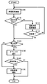
- FIG. 4 is a flowchart relating to the control parameter adjustment function of the control system in this embodiment.
- the control device 140 is in the activated state of the time monitoring function that monitors and stores the elapsed time since the previous adjustment of the control parameter (step S100), and the elapsed time has passed a predetermined time. Is determined (step S110).
- step S110 an operation monitoring function for storing an evaluation amount such as positioning accuracy and the magnitude of vibration amplitude at the time of settling is started (step S111), and the stored evaluation amount is set in advance. It is determined whether adjustment is necessary by comparing the threshold values (step S112). If the determination result in step S112 is NO, the process returns to step S100.
- step S110 or step S112 the notification confirmation setting is made to notify the operator and determine whether or not adjustment is necessary when adjustment is necessary for the control parameter set in advance for the apparatus.
- Step S120 if the confirmation result is YES, that is, if the setting is made to make the operator judge, the necessity confirmation screen is displayed on the display device 141, and the operator (Step S130), and the operator's determination result confirms whether or not adjustment is performed (step S140). If the confirmation result in step S140 is NO, the process ends without adjusting the control parameter.
- step S120 If the determination result in step S120 is NO or the determination result in step S140 is YES, characteristic parameter adjustment (automatic adjustment function) is performed (step S150), and the process is performed when the automatic adjustment function ends. finish.
- the specified time in step S110, the threshold value of the evaluation amount in step S112, and the notification confirmation setting in step S120 can be set as device-specific setting values, but the control device 140 has an adjustment condition setting function, and the operator It is effective that these can be set freely.
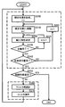
- FIG. 5 is a flowchart showing details of the automatic adjustment function.
- characteristic measurement open loop characteristic and sensitivity function measurement
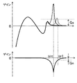
- FIG. 6 is a flowchart showing details of the filter redesign process.
- FIG. 7 is a diagram showing a design concept of a notch filter which is a filter in the present embodiment.
- the control device 140 first determines the maximum gain specification Gs that should be satisfied in the sensitivity function (step S300), and then determines the frequency having the greatest sensitivity in all control characteristics as the center frequency ⁇ c of the filter. Determine (step S310). Subsequently, all the acquired frequency characteristics have sensitivity characteristics larger than the specification Gs, and the frequency farthest from ⁇ c is ⁇ 1, and the gain of the open loop characteristic at ⁇ 1 is G2 (step S320). Next, an ideal filter gain Gn at ⁇ 1 is obtained (step S330). Next, the filter width ⁇ is determined using the filter gain Gn, the frequency ⁇ 1, and the center frequency ⁇ c (step S340). Then, the filter is constructed by substituting the obtained filter parameter into the above-described equation 2 to determine each filter coefficient (step S350), and the process is terminated.
- the filter gain Gn and the filter width ⁇ are obtained from the following formulas 5 and 6, respectively.
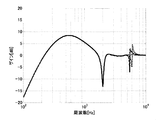
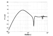
- FIG. 8 is a diagram showing the frequency characteristics of the output of the controlled object 156 in FIG.
- FIG. 8 schematically shows the frequency characteristics of the controlled object measured at three different specified positions. As can be seen from FIG. 8, at the resonance point near the frequency of 5 kHz, the resonance frequency varies depending on the difference in the specified position.
- FIG. 9 shows an open loop in the case where a notch filter set in advance corresponding to a representative position (a position indicated by a solid line in the figure) is applied to the control object 156 having the frequency characteristics shown in FIG. It is a figure which shows a characteristic.
- FIG. 10 is a sensitivity function corresponding to the open loop characteristics shown in FIG.
- the maximum gain near the resonance frequency is about 5 dB.
- FIG. 11 corresponds to the characteristics of the controlled object shown in FIG. 9 and shows the open loop characteristics when the notch filter is automatically adjusted. Compared with the result of FIG. 9, it can be confirmed that the peak gain is reduced in the characteristics at points other than the representative position.
- FIG. 12 is a sensitivity function corresponding to the open loop characteristics shown in FIG. In FIG. 10, the maximum gain in the vicinity of the resonance frequency is about 5 dB, whereas in FIG. 12 in which the notch filter is automatically adjusted, the gain is greatly reduced to 2 dB or less.
- Factors affecting the accuracy of the positioning control system include, for example, changes in the position of the center of gravity and changes in rigidity of the configuration including the moving body, balance between thrust and inertial force, machine differences associated with component processing accuracy and assembly accuracy, etc. There is a tendency that the influence becomes remarkable as the movable range of the moving body becomes wider. In addition, deterioration of lubricants and adhesives used for components such as linear guides, wear of sliding / connecting parts, secular changes such as deformation and creep, or floor rigidity, ground vibration, vibration from peripheral devices The installation environment of the positioning device such as propagation also affects the characteristic variation of the controlled object. Therefore, it is important to realize uniform and accurate mechanism characteristics over the entire operating range of the moving body and to suppress fluctuations in the characteristics of the controlled object.
- control parameter is determined based on the characteristics and response at the position of the control target at the time of adjustment execution, it is not possible to perform appropriate adjustment in consideration of the position dependency of the control target. It has been difficult to maintain robustness against position dependence over the entire movable range.
- a moving device that moves the moving object, a position detecting device that detects the position of the moving object, a measuring device that measures the control characteristics of the control system of the moving device at a plurality of positions, Based on a plurality of measurement results obtained by the measurement device, an adjustment value calculation unit for calculating an adjustment value for adjusting a control parameter of the control system of the mobile device, and based on a detection result and a control parameter of the position detection device
- the movement target is controlled to move to a predetermined target position
- the control parameter adjustment unit that adjusts the control parameter based on the adjustment value calculated by the adjustment value calculation unit is provided.
- the positioning control system can be made highly robust with respect to the position dependency of the controlled object in the entire movable range and the machine difference for each apparatus.
- the configuration of the positioning device is not limited to that shown in FIG. That is, it goes without saying that the type, number and arrangement of motors, the configuration of the linear guide, and the like can be freely designed according to the purpose.
- the positioning control system according to the first embodiment is applied to a component mounting apparatus, and includes a control device 140A that controls the operation of the entire component mounting apparatus as a positioning control system. .
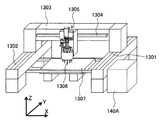
- FIG. 13 is a diagram schematically showing the overall configuration of the component mounting apparatus according to the present embodiment.
- a Y beam 1303 movable in the Y-axis direction in the drawing is driven and positioned in the Y-axis direction with respect to the base by two Y linear motors 1301 and 1302.
- the mounting head 1305 is driven and positioned in the X-axis direction with respect to the Y beam 1303 by the X linear motor 1304. Accordingly, the mounting head 1305 is freely positioned on the XY plane.
- the mounting head 1305 is provided with a plurality of suction nozzles 1306. Each suction nozzle 1306 sucks and holds a component and is moved in the Z direction to mount the component at an arbitrary position on the printed circuit board 1307.
- the position of the center of gravity of the movable mass in the X-axis direction including the mounting head 1305 varies depending on the position of the mounting head 1305 as in FIG. 1, and the characteristics of the control target viewed from the Y linear motors 1301 and 1302 are position-dependent. Have sex. Further, since the Y beam 1303 has a so-called gantry structure, its deformation and the influence of the eccentric gravity center cannot be ignored.
- the present invention provides an effective solution to such positional dependency and characteristic variation accompanying deformation, and provides a suitable positioning control system for the component mounting apparatus as shown in FIG. can do.
- the positioning control system according to the first embodiment is applied to a semiconductor manufacturing / inspection apparatus, and a control device 140B that controls the operation of the entire semiconductor manufacturing / inspection apparatus as a positioning control system; It has.
- FIG. 14 is a diagram schematically showing an overall configuration of the semiconductor manufacturing / inspection apparatus according to the present embodiment.
- a Y linear guide 1402 is arranged on the base 1401 in the Y-axis direction in the drawing, and the Y table 1404 is freely restrained only in the Y-axis direction and is positioned in the Y-axis direction by the Y linear motor 1403.
- the top table 1407 is freely restrained only in the X axis direction with respect to the Y table 1404 by the X linear guide 1405, and is positioned in the X axis direction by the X linear motor 1406.
- the wafer 1408 mounted on the top table 1407 is positioned in the XY axis direction with respect to the base 1404.
- the wafer 1408 is irradiated with an optical beam or electron beam 1409 for semiconductor manufacturing or inspection, and semiconductor manufacturing or inspection is performed.
- the position of the center of gravity of the movable mass in the X-axis direction including the top table 1407 and the wafer 1408 varies depending on the position of the top table 1407. Therefore, the characteristics of the controlled object viewed from the Y linear motor 1403 are position dependent.
- manufacturing / inspection devices are required to have particularly precise positioning and vibration suppression. For example, even Y table 1404 flexural vibrations and slight fluctuations in frictional resistance may cause deterioration in control performance. It becomes.
- the present invention provides an effective solution to such demands for characteristic fluctuations such as position dependence and severe control performance, and is suitable for the semiconductor manufacturing / inspection apparatus as shown in FIG.
- a positioning control system can be provided.
- the positioning control system according to the first embodiment is applied to a printed circuit board processing apparatus, and includes a control device 140C that controls the operation of the entire printed circuit board processing apparatus as a positioning control system. ing.
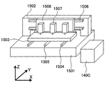
- FIG. 15 is a diagram schematically showing the overall configuration of the printed circuit board processing apparatus according to the present embodiment.
- a table 1503 is freely installed on the bed 1501 via two guide guides 1504 in the Y-axis direction in the figure.
- the table 1503 is positioned in the Y-axis direction by the Y feed screw 1505.
- a portal column rail 1502 is provided on the bed 1501, and a slide plate 1508 is attached to the side surface of the portal column rail 1506 via an X guide guide 1506.
- the slide plate 1508 is positioned in the X-axis direction with respect to the portal column rail 1506 by X drive means (not shown). Thereby, the slide plate 1508 and the table 1503 are relatively positioned in the XY axis directions.
- a plurality of drill units 1507 are disposed on the slide plate 1508, and a printed circuit board disposed on the table 1503 is processed.
- the reaction force due to substrate processing acts on the portal column rail 1506 via the drill unit 1507 and the slide plate 1508. Since the position where the reaction force acts differs depending on the position of the slide plate 1508, there is a dependency of characteristics depending on the position. In addition, deformation due to reaction force, periodic disturbance of the drill, and the weight of the apparatus are greatly affected by the installation environment, which causes deterioration of control performance.
- the present invention provides an effective solution to such characteristic fluctuations, and can provide a suitable positioning control system for the printed circuit board processing apparatus as shown in FIG.
- Base table 110 Top table 111 X-axis direction motor movable element 120 X-axis direction drive mechanism 121 X-axis direction linear guide 122 X-axis direction drive motor stator 123 X-axis direction linear scale 124 Y-axis direction drive motor movable element 125 Scale head 126 Y table 130 Y axis direction drive mechanism 131 Y axis direction linear guide 132 Y axis direction drive motor stator 133 Y axis direction linear scales 140, 140A, 140B, 140C Controller 141 Display unit 142 Input unit 143 Storage unit 144 Measuring unit 145 Adjustment value calculation unit 146 Control parameter adjustment unit
Landscapes
- Engineering & Computer Science (AREA)
- Physics & Mathematics (AREA)
- General Physics & Mathematics (AREA)
- Automation & Control Theory (AREA)
- Human Computer Interaction (AREA)
- Manufacturing & Machinery (AREA)
- Control Of Position Or Direction (AREA)
Abstract
トップテーブル(110)を移動する移動装置(120、130)と、トップテーブル(110)の位置を検出する位置検出装置(112、125)と、移動装置(120、130)の制御系の制御特性を複数の位置において測定する測定装置(144)と、測定装置(144)により得られた複数の測定結果に基づいて、移動装置(120、130)の制御系の制御パラメータを調整するための調整値を演算する調整値演算部(145)と、位置検出装置(112、125)の検出結果と制御パラメータとに基づいて、トップテーブル(110)が予め定めた目標位置に移動するよう制御するとともに、調整値演算部(145)で演算された調整値に基づいて、制御パラメータを調整する制御パラメータ調整部(146)とを備える。これにより、可動範囲全域におけるい制御対象の位置依存性や装置ごとの機差に対してロバスト性の高い位置決め制御システムを提供することができる。
Description
本発明は、移動体の位置を制御する位置決め制御システムに関する。
各種加工装置やメカトロニクス製造・検査装置などの産業機械においては、装置を構成する移動体の位置決めの精度が加工品やメカトロニクス製品の品質を決定する大きな要因として挙げられる。例えば、プリント基板の加工装置、或いは、基板への部品実装装置などにおいても、移動体の位置決めを制御する位置決め制御システムは製品の品質の良否を左右する重要な機構要素として認識されており、その位置決めの精度向上に向けた技術開発が進められている。
このような位置決め制御システムに関する技術として、例えば、特許文献1(特開2005-332213号公報)には、サーボシステムを上位コントローラとサーボアンプとサーボモータとから形成し、上位コントローラからサーボシステムの負荷機器の位置決め制御を行う操作指令が入力されたサーボアンプでは、位置決め制御のための位置・速度調節演算結果に基づいた駆動電流により負荷機器に連結されたサーボモータを可変速駆動するサーボシステムにおいて、操作指令が発せられなくても、サーボアンプに負荷機器が複数回の往復運動を連続的に行うサーボシステムが開示されている。
位置決め制御システムの精度に影響する要因としては、例えば、移動体を含む構成の重心位置の変化や剛性の変化、推力と慣性力のバランス、構成部品の加工精度や組立精度に伴う機差等があり、移動体の可動範囲が広くなればなるほど、その影響が顕著になる傾向にある。また、リニアガイドなどの構成部品に用いられる潤滑剤や接着材等の劣化、摺動・接続部分の摩耗、変形やクリープ等の経年変化、或いは、床剛性や地振動、周辺装置のからの振動伝搬のような位置決め装置の設置環境も制御対象の特性変動に影響を与える。したがって、移動体の稼動範囲の全域で均等かつ正確な機構特性を実現し、制御対象の特性変動を抑制することが重要である。
しかしながら、上記従来技術においては、調整実行時における制御対象の位置での特性及び応答をもとに制御パラメータを決定するため、制御対象の位置依存性を考慮した適切な調整を行うことができず、したがって、可動範囲全域における位置依存に対してロバスト性を維持することが困難である。
本発明は上記に鑑みてなされたものであり、可動範囲全域における制御対象の位置依存性や装置ごとの機差に対してロバスト性の高い位置決め制御システムを提供することを目的とする。
上記目的を達成するために、本発明は、移動対象を移動する移動装置と、前記移動対象の位置を検出する位置検出装置と、前記移動装置の制御系の制御特性を複数の位置において測定する測定装置と、前記測定装置により得られた複数の前記測定結果に基づいて、前記移動装置の制御系の制御パラメータを調整するための調整値を演算する調整値演算部と、前記位置検出装置の検出結果と前記制御パラメータとに基づいて、前記移動対象が予め定めた目標位置に移動するよう制御するとともに、前記調整値演算部で演算された前記調整値に基づいて、前記制御パラメータを調整する制御パラメータ調整部とを備えたものとする。
本発明によれば、可動範囲全域における制御対象の位置依存性や装置ごとの機差に対してロバスト性の高い位置決め制御システムを提供することができる。
以下、本発明の実施の形態を図面を参照しつつ説明する。
<第1の実施の形態>
本発明の第1の実施の形態を図1~図12を参照しつつ説明する。
本発明の第1の実施の形態を図1~図12を参照しつつ説明する。
図1は、本実施の形態に係る位置決め制御システムの全体構成を概略的に示す図である。図1においては、横方向にX軸、縦方向にY軸をそれぞれ設定する。
図1において、位置決め制御システムは、位置決め制御システムの基部となるベーステーブル100と、移動対象としてのトップテーブル110と、トップテーブル110を移動する移動装置であるX軸方向駆動機構120及びY軸方向駆動機構130と、これらを含む位置決め制御システム全体の動作を制御する制御装置140とから概略構成されている。
本実施の形態に示す位置決め制御システムは、制御装置140の制御によりX軸方向駆動機構120及びY軸方向駆動機構130を動作させてトップテーブル110を移動させ、ベーステーブル100に対するトップテーブル110の位置決めを行うものである。
Y軸方向駆動機構130は、ベーステーブル100上にY軸方向に沿って配置されたY軸方向リニアガイド131、Y軸方向駆動モータ固定子132、及び、Y軸方向リニアスケール133を有している。Y軸方向リニアガイド131には、図示しないスライドユニットが取り付けられており、これによりX軸方向駆動機構120のYテーブル126のY軸方向への移動がガイドされる。また、Yテーブル126に設けられたY軸方向モータ可動子124をY軸方向モータ固定子132に対して駆動することにより、Yテーブル126をY軸方向リニアガイド131に沿って駆動することができる。また、Yテーブル126に設けられたYスケールヘッド125によりY軸方向リニアスケール133を検出することにより、Yテーブル126のY軸方向の位置(座標)を検出することができる。なお、Y軸方向リニアスケール133及びYスケールヘッド125は、移動対象であるトップテーブル110の位置を検出する位置検出装置の一部を構成する。
X軸方向駆動機構120は、Yテーブル126上にX軸方向に沿って配置されたX軸方向リニアガイド121、X軸方向駆動モータ固定子122、及び、X軸方向リニアスケール123を有している。X軸方向リニアガイド121には、図示しないスライドユニットが取り付けられており、これによりトップテーブル110のX軸方向への移動がガイドされる。また、トップテーブル110に設けられたX軸方向モータ可動子111をX軸方向モータ固定子122に対して駆動することにより、トップテーブル110をX軸方向リニアガイド121に沿って駆動することができる。また、トップテーブル110に設けられたXスケールヘッド112によりX軸方向リニアスケール123を検出することにより、トップテーブル110のX軸方向の位置(座標)を検出することができる。なお、X軸方向リニアスケール123及びXスケールヘッド112は、移動対象であるトップテーブル110の位置を検出する位置検出装置の一部を構成する。
Y軸方向駆動モータ可動子124によってY軸方向に駆動される構成の質量は、Yテーブル126、X軸方向リニアガイド123、X軸方向モータ固定子122、トップテーブル110などによって構成される。Y軸方向の可動質量の重心位置はトップテーブル110の位置によって大きく変化すため、Y軸方向の制御系からみれば共振周波数や共振ピークの大きさが変化するといった制御対象の特性変動となる。また、X軸方向やY軸方向リニアガイド121、131の取り付け精度や潤滑状態、Yテーブル126の撓みなどによって、トップテーブル110の位置により負荷が変動することが考えられる。
制御装置140は、各種情報や設定画面を表示する表示装置141と、各種情報や設定値を入力する入力装置142と、各種情報や設定値を記憶する記憶部143と、位置決め制御システムにおける制御系の制御特性(開ループ特性や閉ループ特性)を複数の位置において測定する測定装置144と、測定装置144により得られた複数の測定結果に基づいて、移動装置の制御系の制御パラメータを調整するための調整値を演算する調整値演算部145と、位置検出装置の検出結果と制御パラメータとに基づいて、移動対象であるトップテーブル110が予め定めた目標位置に移動するよう制御するとともに、調整値演算部145で演算された調整値に基づいて、制御パラメータを調整する制御パラメータ調整部146とを有している。
図2は、本実施の形態における位置決め制御システムの制御系を示す機能ブロック図である。なお、図2においては、説明の簡単のために1つの軸方向(例えばX軸方向)の制御系のみを図示しているが、その他の軸方向(例えばY軸方向)についても同様の構成を有している。
図2において、指令生成部150は、トップテーブル110の目標位置への移動を位置指令として出力するものであり、予め設定されて記憶部143に記憶された目標移動量、速度、加速度などの移動パラメータを用いて位置指令を生成して出力する。差分器151は、指令生成部150の出力である位置指令と制御対象156の出力156aである現在位置(言い換えると、位置指令により制御されるY軸方向モータ可動子124にともなってYスケールヘッド125で検出されるY軸方向の位置)との差分を信号処理部152に出力する。信号処理部152は、制御器153とフィルタ154から構成され、制御対象156に対する操作量を演算して出力する。
信号処理部152の制御器153は、例えばPID制御器などを用いて実現することができる。本実施の形態における制御器153の伝達関数Gcは、ラプラス演算子をs、比例ゲインをKp、積分ゲインをKi、微分ゲインをKdとすると、下記の式1により表される。

信号処理部152のフィルタ154は、例えば共振周波数の振動を抑制するノッチフィルタなどを用いて実現することができる。本実施の形態におけるフィルタ154の伝達関数Gfは、共振周波数をωc、ノッチの幅を決めるパラメータをζとすると、下記の式2により表される。

ここで、仮想的な推力外乱d(例えば正弦波)を制御対象156への入力に設けた加算器155により印加した場合、本実施の形態の制御系における開ループ特性(図2におけるu2からu1までの伝達特性)、及び、感度関数(図2におけるdからu2までの伝達関数)は、それぞれ、下記式3及び式4により表される。


一般に、開ループ特性は制御系の安定性評価に適しており、また、感度関数は外乱抑圧特性の評価に適している。
本実施の形態では、制御パラメータ調整部146により、信号処理部152のフィルタ154(ノッチフィルタ)のパラメータを制御パラメータとして調整する。
図3は、位置決め制御システムにおける制御系の制御特性を測定装置により測定する複数(本実施の形態では9箇所)の位置の一例を示す図である。なお、図3では、説明の簡単のために一部の構成要素のみを図示している。
図3において、位置166は、Yテーブル126がY軸方向のストローク中央付近にある場合を示している。また、位置163及び位置169はYテーブル126がY軸方向の正側ストロークエンド(図3中上側)および負側ストロークエンド(図3中下側)付近にある場合を図示したものである。Y軸方向のストローク中央付近に示したYテーブル126には、トップテーブル110がX軸方向のストローク中央付近の位置165、及び左右両ストロークエンド付近の位置164、166にある場合を図示している。同様に、Y軸方向正側のストロークエンドに示したYテーブル126には、トップテーブル110がX軸方向のストローク中央付近の位置162、及び左右両ストロークエンド付近の位置161、163にある場合を図示している。また、Y軸方向負側のストロークエンドに示したYテーブル126には、トップテーブル110がX軸方向のストローク中央付近の位置168、及び左右両ストロークエンド付近の位置167、169にある場合を図示している。
図3において示した9つのトップテーブル110の位置161~169は、本実施例における特性測定の規定位置を示している。このように特性測定の位置を設定することで、X軸及びY軸方向のそれぞれに関して、中央付近からストロークエンドに向かって特性が変化する場合に対応してその端点での特性を取得することができる。これにより、可動範囲内での安定性の確保をより少ない数の規定位置で実現することが可能である。ここで、特性測定は、実際にトップテーブル110を駆動して行われるため、ある程度の動作範囲が必要となる。特性測定の規定位置は、特性測定中にストロークエンドに達することなく、かつストロークエンドに近い位置を選択する必要があり、例えばストロークエンドから10%以内の位置を選択することが望ましい。ただし、可動範囲の大きさや特性変動の特徴に応じて、規定位置の数や位置の選び方は自由に設計することが可能であり、オペレータが任意に規定位置を設定可能な測定位置設定装置を有することが望ましい。特に、特性変化が大きいと予想される点や通常時に頻繁に位置決め動作を行う点などを規定位置に設定することは、本発明の実施形態として有効な効果をもたらすことが期待される。すなわち、通常運転において多く位置決め動作が行われる座標を目標位置の履歴に基づいて決定し、その位置を規定位置として特性測定することが有効である。
図4は、本実施例における制御系の制御パラメータの調整機能に係るフローチャートである。
図4において、制御装置140は、前回の制御パラメータの調整実施からの経過時間を監視して記憶する時間監視機能の起動状態であり(ステップS100)、経過時間が予め定めた規定時間を経過したかどうかを判定する(ステップS110)。ステップS110での判定結果がNOの場合は、位置決め精度や整定時の振動振幅の大きさなどの評価量を記憶する運転監視機能を起動し(ステップS111)、記憶した評価量と予め設定された閾値を比較して調整が必要か否かを判別する(ステップS112)。ステップS112での判定結果がNOの場合は、ステップS100に戻る。
ステップS110又はステップS112での判定結果がYESの場合は、予め装置に対して設定する制御パラメータに調整が必要となった場合にオペレータに通知して調整の要否を判断させる通知確認設定となっているかどうかを確認し(ステップS120)、確認結果がYESとなっている場合、すなわち、オペレータに判断させる設定となっている場合には、表示装置141に要否確認の画面を表示してオペレータに通知し(ステップS130)、オペレータの判断結果が調整実施を行うかどうかを確認する(ステップS140)。ステップS140での確認結果がNOの場合には、制御パラメータの調整を実施せずに処理を終了する。
また、ステップS120での判定結果がNO、又はステップS140での判定結果がYESの場合には、特性パラメータの調整(自動調整機能)を実施し(ステップS150)、自動調整機能が終了すると処理を終了する。
なお、ステップS110における規定時間、ステップS112における評価量の閾値およびステップS120における通知確認設定は、装置固有の設定値とすることも可能であるが、制御装置140が調整条件設定機能を備え、オペレータがこれらを自由に設定可能とすることは有効である。
図5は、自動調整機能の詳細を示すフローチャートである。
図5において、制御装置140は、まず、特性測定の規定位置を設定し、ループパラメータをi=1に初期化する(ステップS200)。次に、予め設定された複数の規定位置のうちi番目の座標にトップテーブルを移動させ、ループパラメータをk=1に初期化する(ステップS210)。続いて、装置の移動自由度のうちk番目の軸に対して特性測定(開ループ特性及び感度関数の測定)を行って記憶部143に記憶させ(ステップS220)、全軸の特性測定が完了したかどうかを判定する(ステップS230)。ステップS230での判定結果がNOの場合は、ループパラメータをk=k+1とし、ステップS220に戻る。ステップS230での判定結果がYESの場合は、全規定位置での特性測定が完了したかどうかを判定し(ステップS240)、判定結果がNOの場合は、ループパラメータをi=i+1とし、ステップS210に戻る。ステップS240での判定結果がYESの場合は、測定した全ての規定位置における制御特性が予め設定された仕様を満足しているかどうかを判定し(ステップS250)、判定結果がYESの場合には、処理を終了する。ステップS250での判定結果がNOの場合には、フィルタの再設計処理を行い(ステップS260)、設計したフィルタを制御系に適用して(ステップS270)、ステップS200の処理に戻る。
図6は、フィルタの再設計処理の詳細を示すフローチャートである。また、図7は、本実施の形態におけるフィルタであるノッチフィルタの設計概念を示す図である。
図6において、制御装置140は、まず、感度関数において満足すべき最大ゲインの仕様Gsを決定し(ステップS300)、次に、全制御特性で最も大きな感度を持つ周波数をフィルタの中心周波数ωcと決定する(ステップS310)。続いて、取得した全ての周波数特性で仕様Gsよりも大きい感度特性を持ち、かつωcから最も離れた周波数をω1とし、ω1での開ループ特性のゲインをG2とする(ステップS320)。次に、ω1での理想的なフィルタゲインGnを求める(ステップS330)。次に、フィルタゲインGn、周波数ω1、及び中心周波数ωcを用いてフィルタ幅ζを決定する(ステップS340)。そして、得られたフィルタパラメータを前述の式2に代入することにより各フィルタ係数を決定することでフィルタを構築し(ステップS350)、処理を終了する。
なお、フィルタゲインGn及びフィルタ幅ζは、それぞれ、下記式5及び式6から求められる。


図8は、図2における制御対象156の出力の周波数特性を示す図である。
図8では、3つの異なる規定位置において測定される制御対象の周波数特性を模式的に示している。図8からわかるように、周波数5kHz付近の共振点において、その共振周波数が規定位置の違いにより異なっている。
図9は、図8に示した周波数特性を有する制御対象156に対して、予め代表位置(図中の実線で示す特性を示す位置)に対応させて設定したノッチフィルタを適用した場合の開ループ特性を示す図である。また、図10は、図9で示した開ループ特性に対応した感度関数である。
図9に示した開ループ特性の伝達関数からは、安定性の指標となる安定余有や制御帯域などを検討可能である。
図10においては、共振周波数付近での最大ゲインが約5dBである。
図11は、図9で示した制御対象の特性に対応しており、ノッチフィルタを自動調整した場合の開ループ特性を示している。図9の結果と比較して代表位置以外の点での特性においてピークゲインが低減していることが確認できる。
図12は、図11で示した開ループ特性に対応した感度関数である。図10においては、共振周波数付近での最大ゲインが約5dBであったのに対し、ノッチフィルタを自動調整した図12では、2dB以下となり大きく低減している。
以上のように構成した本実施の形態の効果を説明する。
位置決め制御システムの精度に影響する要因としては、例えば、移動体を含む構成の重心位置の変化や剛性の変化、推力と慣性力のバランス、構成部品の加工精度や組立精度に伴う機差等があり、移動体の可動範囲が広くなればなるほど、その影響が顕著になる傾向にある。また、リニアガイドなどの構成部品に用いられる潤滑剤や接着材等の劣化、摺動・接続部分の摩耗、変形やクリープ等の経年変化、或いは、床剛性や地振動、周辺装置のからの振動伝搬のような位置決め装置の設置環境も制御対象の特性変動に影響を与える。したがって、移動体の稼動範囲の全域で均等かつ正確な機構特性を実現し、制御対象の特性変動を抑制することが重要である。しかしながら、例えば、調整実行時における制御対象の位置での特性及び応答をもとに制御パラメータを決定する場合には、制御対象の位置依存性を考慮した適切な調整を行うことができず、したがって、可動範囲全域における位置依存に対してロバスト性を維持することが困難であった。
これに対し本実施の形態においては、移動対象を移動する移動装置と、移動対象の位置を検出する位置検出装置と、移動装置の制御系の制御特性を複数の位置において測定する測定装置と、測定装置により得られた複数の測定結果に基づいて、移動装置の制御系の制御パラメータを調整するための調整値を演算する調整値演算部と、位置検出装置の検出結果と制御パラメータとに基づいて、移動対象が予め定めた目標位置に移動するよう制御するとともに、調整値演算部で演算された調整値に基づいて、制御パラメータを調整する制御パラメータ調整部とを備えた構成としたので、位置決め制御システムを可動範囲全域における制御対象の位置依存性や装置ごとの機差に対してロバスト性の高いものとすることができる。
なお、本実施の形態は、位置決め装置の構成を図1に限定するものではない。すなわち、モータの種類や数や配置、リニアガイドの構成などは目的に合わせて自由に設計可能であることは言うまでもない。
<第2の実施の形態>
本発明の第2の実施の形態を図13を参照しつつ説明する。
本発明の第2の実施の形態を図13を参照しつつ説明する。
本実施の形態は、第1の実施の形態に係る位置決め制御システムを部品実装装置に適用したものであり、位置決め制御システムとしての部品実装装置全体の動作を制御する制御装置140Aとを備えている。
図13は、本実施の形態に係る部品実装装置の全体構成を概略的に示す図である。
図13において、図中Y軸方向に可動なYビーム1303は、2つのYリニアモータ1301および1302によってベースに対してY軸方向に駆動・位置決めされる。同様に実装ヘッド1305は、Xリニアモータ1304によってYビーム1303に対してX軸方向に駆動・位置決めされる。これにより実装ヘッド1305は、XY平面で自由に位置決め行われる。実装ヘッド1305には、複数の吸着ノズル1306が備えられ、それぞれの吸着ノズル1306は部品を吸着して保持するとともに、Z方向に可動されてプリント基板1307上の任意の位置に部品を実装する。
図13において、図1と同様に実装ヘッド1305を含むX軸方向の可動質量の重心位置は、実装ヘッド1305の位置によって変動するため、Yリニアモータ1301および1302からみた制御対象の特性は位置依存性を有する。また、Yビーム1303は、いわゆるガントリ構造となっているため、その変形や偏重心の影響は無視できない。
このような位置依存性や変形に伴う特性変動に対して、本発明は有効な解決手段を与えるものであり、図13に示したような部品実装装置に対して、好適な位置決め制御システムを提供することができる。
<第3の実施の形態>
本発明の第3の実施の形態を図14を参照しつつ説明する。
本発明の第3の実施の形態を図14を参照しつつ説明する。
本実施の形態は、第1の実施の形態に係る位置決め制御システムを半導体製造・検査装置に適用したものであり、位置決め制御システムとしての半導体製造・検査装置全体の動作を制御する制御装置140Bとを備えている。
図14は、本実施の形態に係る半導体製造・検査装置の全体構成を概略的に示す図である。
図14において、ベース1401上には図中Y軸方向にYリニアガイド1402が配置され、Yテーブル1404はY軸方向にのみ自由に拘束されており、Yリニアモータ1403によってY軸方向に位置決めされる。トップテーブル1407は、Xリニアガイド1405によってYテーブル1404に対してX軸方向にのみ自由に拘束されており、Xリニアモータ1406によってX軸方向に位置決めされる。これにより、トップテーブル1407上に搭載されたウェハ1408は、ベース1404に対してXY軸方向に位置決めが行われる。ウェハ1408上には、半導体製造または検査のための光学ビームや電子ビーム等1409が照射され、半導体の製造や検査が行われる。
図14において、トップテーブル1407およびウェハ1408を含むX軸方向の可動質量の重心位置は、トップテーブル1407の位置によって変動するため、Yリニアモータ1403からみた制御対象の特性は位置依存性を有する。また、半導体デザインルールの微細化に伴い、製造・検査装置には特に精密な位置決めや振動抑制が要求されており、例えばYテーブル1404のたわみ振動やわずかな摩擦抵抗の変動でも制御性能の悪化要因となる。
このような位置依存性などの特性変動や厳しい制御性能の要求に対して、本発明は有効な解決手段を与えるものであり、図14に示したような半導体製造・検査装置に対して、好適な位置決め制御システムを提供することができる。
<第4の実施の形態>
本発明の第4の実施の形態を図15を参照しつつ説明する。
本発明の第4の実施の形態を図15を参照しつつ説明する。
本実施の形態は、第1の実施の形態に係る位置決め制御システムをプリント基板加工装置に適用したものであり、位置決め制御システムとしてのプリント基板加工装置全体の動作を制御する制御装置140Cとを備えている。
図15は、本実施の形態に係るプリント基板加工装置の全体構成を概略的に示す図である。
図15において、ベッド1501上には2本の案内ガイド1504を介してテーブル1503が図中Y軸方向に自由に設置されている。Y送りねじ1505によってテーブル1503はY軸方向に位置決めされる。また、ベッド1501上には門型コラムレール1502が備えられ、門型コラムレール1506側面にX案内ガイド1506を介してスライド板1508が取り付けられている。スライド板1508は、X駆動手段(図示せず)によって門型コラムレール1506に対してX軸方向に位置決めされる。これによりスライド板1508とテーブル1503はXY軸方向に相対的に位置決めされる。スライド板1508には複数のドリルユニット1507が配置され、テーブル1503上に配置されるプリント基板の加工を行う。
図15において、基板加工による反力は、ドリルユニット1507、スライド板1508を介して門型コラムレール1506に作用する。スライド板1508の位置によって反力の作用する位置が異なるため、位置による特性の依存性が存在する。また、反力による変形やドリルの周期外乱、また装置重量が大きいため設置環境の影響も大きく受け、制御性能悪化の要因となる。
このような特性変動に対して、本発明は有効な解決手段を与えるものであり、図15に示したようなプリント基板加工装置に対して、好適な位置決め制御システムを提供することができる。
100 ベーステーブル
110 トップテーブル
111 X軸方向モータ可動子
120 X軸方向駆動機構
121 X軸方向リニアガイド
122 X軸方向駆動モータ固定子
123 X軸方向リニアスケール
124 Y軸方向駆動モータ可動子
125 スケールヘッド
126 Yテーブル
130 Y軸方向駆動機構
131 Y軸方向リニアガイド
132 Y軸方向駆動モータ固定子
133 Y軸方向リニアスケール
140、140A、140B、140C 制御装置
141 表示装置
142 入力装置
143 記憶部
144 測定装置
145 調整値演算部
146 制御パラメータ調整部
110 トップテーブル
111 X軸方向モータ可動子
120 X軸方向駆動機構
121 X軸方向リニアガイド
122 X軸方向駆動モータ固定子
123 X軸方向リニアスケール
124 Y軸方向駆動モータ可動子
125 スケールヘッド
126 Yテーブル
130 Y軸方向駆動機構
131 Y軸方向リニアガイド
132 Y軸方向駆動モータ固定子
133 Y軸方向リニアスケール
140、140A、140B、140C 制御装置
141 表示装置
142 入力装置
143 記憶部
144 測定装置
145 調整値演算部
146 制御パラメータ調整部
Claims (11)
- 移動対象を移動する移動装置と、
前記移動対象の位置を検出する位置検出装置と、
前記移動装置の制御系の制御特性を複数の位置において測定する測定装置と、
前記測定装置により得られた複数の前記測定結果に基づいて、前記移動装置の制御系の制御パラメータを調整するための調整値を演算する調整値演算部と、
前記位置検出装置の検出結果と前記制御パラメータとに基づいて、前記移動対象が予め定めた目標位置に移動するよう制御するとともに、前記調整値演算部で演算された前記調整値に基づいて、前記制御パラメータを調整する制御パラメータ調整部と
を備えたことを特徴とする位置決め制御システム。 - 請求項1記載の位置決め制御システムにおいて、
前記制御パラメータは、前記移動装置の制御系に適用するノッチフィルタのパラメータであることを特徴とする位置決め制御システム。 - 請求項1記載の位置決め制御システムにおいて、
前記測定装置により制御特性が測定される複数の位置のうちの少なくとも1つは、前記移動装置による前記移動対象の移動可能範囲の境界からその移動可能範囲の中心までの距離において、境界側から10%以内にあることを特徴とする位置決め制御システム。 - 請求項1記載の位置決め制御システムにおいて、
前記測定装置により制御特性が測定される位置は、前記目標位置の履歴に基づいて設定されることを特徴とする位置決め制御システム。 - 請求項1記載の位置決め制御システムにおいて、
前記測定装置により制御特性が測定される位置をオペレータが設定する測定位置設定装置を備えたことを特徴とする位置決め制御システム。 - 請求項1記載の位置決め制御システムにおいて、
前記制御パラメータの調整の実行条件をオペレータが設定する調整条件設定装置を備えたことを特徴とする位置決め制御システム。 - 請求項1記載の位置決め制御システムにおいて、
前記制御装置は、前記測定装置により測定される制御特性に基づいて、前記制御パラメータの調整を実行するかどうかを判定することを特徴とする位置決め制御システム。 - 請求項1記載の位置決め制御システムにおいて、
前記制御装置は、前記制御パラメータの調整の実行履歴および調整の実行からの経過時間に基づいて、前記制御パラメータの調整を実行するかどうかを判定することを特徴とする位置決め制御システム。 - 請求項1記載の位置決め制御システムを備えた部品実装装置。
- 請求項1記載の位置決め制御システムを備えた半導体製造検査装置。
- 請求項1記載の位置決め制御システムを備えた基板加工装置。
Priority Applications (1)
| Application Number | Priority Date | Filing Date | Title |
|---|---|---|---|
| PCT/JP2013/051288 WO2014115263A1 (ja) | 2013-01-23 | 2013-01-23 | 位置決め制御システム |
Applications Claiming Priority (1)
| Application Number | Priority Date | Filing Date | Title |
|---|---|---|---|
| PCT/JP2013/051288 WO2014115263A1 (ja) | 2013-01-23 | 2013-01-23 | 位置決め制御システム |
Publications (1)
| Publication Number | Publication Date |
|---|---|
| WO2014115263A1 true WO2014115263A1 (ja) | 2014-07-31 |
Family
ID=51227080
Family Applications (1)
| Application Number | Title | Priority Date | Filing Date |
|---|---|---|---|
| PCT/JP2013/051288 Ceased WO2014115263A1 (ja) | 2013-01-23 | 2013-01-23 | 位置決め制御システム |
Country Status (1)
| Country | Link |
|---|---|
| WO (1) | WO2014115263A1 (ja) |
Cited By (4)
| Publication number | Priority date | Publication date | Assignee | Title |
|---|---|---|---|---|
| CN104597818A (zh) * | 2015-01-26 | 2015-05-06 | 北京诺安舟应急缓降机械装置有限公司 | 一种高层救援逃生设备的智能控制方法及系统 |
| JP2017194881A (ja) * | 2016-04-22 | 2017-10-26 | 三菱電機株式会社 | 機械装置、および機械装置の振動制御方法 |
| CN111868658A (zh) * | 2018-04-26 | 2020-10-30 | 欧姆龙株式会社 | 控制系统、控制方法以及控制程序 |
| JP2023155768A (ja) * | 2022-04-11 | 2023-10-23 | オークマ株式会社 | 負荷装置の位置による特性変動を考慮したパラメータ調整装置および方法 |
Citations (3)
| Publication number | Priority date | Publication date | Assignee | Title |
|---|---|---|---|---|
| JPH08194503A (ja) * | 1995-01-19 | 1996-07-30 | Omron Corp | 調節計 |
| JP2009122779A (ja) * | 2007-11-12 | 2009-06-04 | Mitsubishi Electric Corp | 制御システムおよび制御支援装置 |
| JP2010257314A (ja) * | 2009-04-27 | 2010-11-11 | Takenaka Komuten Co Ltd | アクティブフィードバック制御装置、方法、及びプログラム |
-
2013
- 2013-01-23 WO PCT/JP2013/051288 patent/WO2014115263A1/ja not_active Ceased
Patent Citations (3)
| Publication number | Priority date | Publication date | Assignee | Title |
|---|---|---|---|---|
| JPH08194503A (ja) * | 1995-01-19 | 1996-07-30 | Omron Corp | 調節計 |
| JP2009122779A (ja) * | 2007-11-12 | 2009-06-04 | Mitsubishi Electric Corp | 制御システムおよび制御支援装置 |
| JP2010257314A (ja) * | 2009-04-27 | 2010-11-11 | Takenaka Komuten Co Ltd | アクティブフィードバック制御装置、方法、及びプログラム |
Cited By (6)
| Publication number | Priority date | Publication date | Assignee | Title |
|---|---|---|---|---|
| CN104597818A (zh) * | 2015-01-26 | 2015-05-06 | 北京诺安舟应急缓降机械装置有限公司 | 一种高层救援逃生设备的智能控制方法及系统 |
| CN104597818B (zh) * | 2015-01-26 | 2017-03-08 | 北京诺安舟应急缓降机械装置有限公司 | 一种高层救援逃生设备的智能控制方法及系统 |
| JP2017194881A (ja) * | 2016-04-22 | 2017-10-26 | 三菱電機株式会社 | 機械装置、および機械装置の振動制御方法 |
| CN111868658A (zh) * | 2018-04-26 | 2020-10-30 | 欧姆龙株式会社 | 控制系统、控制方法以及控制程序 |
| JP2023155768A (ja) * | 2022-04-11 | 2023-10-23 | オークマ株式会社 | 負荷装置の位置による特性変動を考慮したパラメータ調整装置および方法 |
| JP7788921B2 (ja) | 2022-04-11 | 2025-12-19 | オークマ株式会社 | 負荷装置の位置による特性変動を考慮したパラメータ調整装置および方法 |
Similar Documents
| Publication | Publication Date | Title |
|---|---|---|
| JP5127934B2 (ja) | 機械運動軌跡測定装置、数値制御工作機械および機械運動軌跡測定方法 | |
| US10969221B2 (en) | Active damping of a measuring device | |
| CA2828826C (en) | Coordinate measuring machine | |
| JP6199003B1 (ja) | 機械運動軌跡測定装置 | |
| JP5566469B2 (ja) | 数値制御方法 | |
| US8810181B2 (en) | Control apparatus and measuring apparatus | |
| WO2014115263A1 (ja) | 位置決め制御システム | |
| US20160370786A1 (en) | Trajectory measuring device, numerical control device, and trajectory measuring method | |
| CN104076740B (zh) | 数控装置 | |
| JP6630500B2 (ja) | 作業装置及びその制御方法 | |
| EP3612787A1 (en) | Measuring apparatus counterbalance | |
| US9673021B2 (en) | Positioning control device | |
| JP7264776B2 (ja) | パラメータの設定方法、及び、制御装置 | |
| CN113614661A (zh) | 数控装置及机器学习装置 | |
| JP5225060B2 (ja) | 機械運動測定装置 |
Legal Events
| Date | Code | Title | Description |
|---|---|---|---|
| 121 | Ep: the epo has been informed by wipo that ep was designated in this application |
Ref document number: 13872422 Country of ref document: EP Kind code of ref document: A1 |
|
| NENP | Non-entry into the national phase |
Ref country code: DE |
|
| 122 | Ep: pct application non-entry in european phase |
Ref document number: 13872422 Country of ref document: EP Kind code of ref document: A1 |
|
| NENP | Non-entry into the national phase |
Ref country code: JP |