WO2014115259A1 - 車両の振動解析方法及び振動解析装置 - Google Patents
車両の振動解析方法及び振動解析装置 Download PDFInfo
- Publication number
- WO2014115259A1 WO2014115259A1 PCT/JP2013/051266 JP2013051266W WO2014115259A1 WO 2014115259 A1 WO2014115259 A1 WO 2014115259A1 JP 2013051266 W JP2013051266 W JP 2013051266W WO 2014115259 A1 WO2014115259 A1 WO 2014115259A1
- Authority
- WO
- WIPO (PCT)
- Prior art keywords
- vibration
- vehicle
- road surface
- value
- transfer function
- Prior art date
- Legal status (The legal status is an assumption and is not a legal conclusion. Google has not performed a legal analysis and makes no representation as to the accuracy of the status listed.)
- Ceased
Links
Images





Classifications
-
- G—PHYSICS
- G01—MEASURING; TESTING
- G01M—TESTING STATIC OR DYNAMIC BALANCE OF MACHINES OR STRUCTURES; TESTING OF STRUCTURES OR APPARATUS, NOT OTHERWISE PROVIDED FOR
- G01M17/00—Testing of vehicles
- G01M17/007—Wheeled or endless-tracked vehicles
- G01M17/04—Suspension or damping
-
- G—PHYSICS
- G01—MEASURING; TESTING
- G01M—TESTING STATIC OR DYNAMIC BALANCE OF MACHINES OR STRUCTURES; TESTING OF STRUCTURES OR APPARATUS, NOT OTHERWISE PROVIDED FOR
- G01M7/00—Vibration-testing of structures; Shock-testing of structures
- G01M7/02—Vibration-testing by means of a shake table
-
- G—PHYSICS
- G01—MEASURING; TESTING
- G01N—INVESTIGATING OR ANALYSING MATERIALS BY DETERMINING THEIR CHEMICAL OR PHYSICAL PROPERTIES
- G01N29/00—Investigating or analysing materials by the use of ultrasonic, sonic or infrasonic waves; Visualisation of the interior of objects by transmitting ultrasonic or sonic waves through the object
- G01N29/44—Processing the detected response signal, e.g. electronic circuits specially adapted therefor
-
- G—PHYSICS
- G01—MEASURING; TESTING
- G01N—INVESTIGATING OR ANALYSING MATERIALS BY DETERMINING THEIR CHEMICAL OR PHYSICAL PROPERTIES
- G01N2291/00—Indexing codes associated with group G01N29/00
- G01N2291/02—Indexing codes associated with the analysed material
- G01N2291/023—Solids
Definitions
- the present invention relates to a vibration analysis method or a vibration analysis apparatus for analyzing vibration generated in a vehicle such as an automobile, and more specifically, to analyze a transfer characteristic of vibration input to a vehicle from a road surface. Related to the apparatus or method.
- the ride comfort performance depends on the transmission characteristics of vibrations applied from the road surface to the vehicle body while the vehicle is running. Therefore, in order to grasp the characteristics of vibration transmitted from the road surface to the vehicle body for the purpose of improving the riding comfort performance of the vehicle, the vibration generated in the vehicle body is actually measured and analyzed and transmitted from the road surface to the vehicle body.
- vibration analysis methods or vibration analysis devices for detecting vibration characteristics to be performed have been proposed.
- a vehicle vibration analysis method for example, as exemplified in Patent Document 1, a vehicle is placed so that wheels are arranged on a table (vibration table) that vibrates vertically and / or horizontally.
- the frequency characteristics of the transfer function are obtained based on the ground load variation and / or the suspension stroke on the ground surface (between the vibration table and the wheel), and the suspension, body, and seat in the body vibration characteristics are obtained. It is shown that the contribution of the influence of each component can be detected.
- a vibration displacement input D is applied to the vehicle body individually from each wheel in various arbitrary modes.
- the vibration analysis technology that measures the vibration Y generated in the vehicle and detects the vibration characteristics of the vehicle, the vibration characteristics due to the vibrations from the front, rear, left and right wheels or the various vibration modes (in-phase input) Therefore, it is possible to detect the difference in vibration characteristics due to the reverse phase input), so that it is possible to obtain information advantageous in improving the structure of the vehicle body for improving the riding comfort performance.
- the vibration analysis performed on the shaking table as described above the vibration state obtained by running the vehicle on the actual road cannot always be reproduced.
- vibrations in the front-rear direction, the left-right direction, the up-down direction, the yaw direction, the roll direction, and the pitch direction are applied to the vehicle on the vibration table.
- vibration frequency characteristics (vibration) obtained in this case
- actual driving obtained from the vehicle running on the road
- arrows in the figure.
- a main object of the present invention is a vibration analysis technique using vibrations measured by running a vehicle on an actual road, and detecting vibration characteristics according to various vibration input modes individually or separately. It is to propose a configuration that can do this.
- the above-described problem is a method of analyzing vibrations of a vehicle, wherein the vehicle travels on a road surface whose height varies at various wavelengths along the traveling direction of the vehicle, and the road surface
- the process of measuring the vibration characteristic value at the vehicle body part of the vehicle traveling above, the process of obtaining at least two vibration input values that cause the vibration characteristic value at the vehicle body part, and the vehicle body part Using the vibration characteristic values in the vehicle as objective variables, using at least two vibration input values as explanatory variables, and using the multiple regression analysis as a partial regression coefficient, the vibration characteristics at the body part for each of the at least two vibration input values Calculating a transfer function of the value.
- the “vibration characteristic value at the body part” may be an arbitrary physical quantity such as an acceleration value representing the vibration characteristic at an arbitrary part of the car body.
- the “at least two vibration input values” may be arbitrary vibration components that are transmitted to the vehicle body and cause the vibration characteristic values.
- it may be a road surface displacement of each wheel or a function thereof while the vehicle is traveling, or may be an unsprung acceleration value or the like in each wheel (in this case, the vibration characteristic value is Or a sprung acceleration value downstream of vibration transmission, etc.).
- At least two vibration input values are, for example, a road surface displacement component that is displaced in the same phase in the left and right front wheels, a road surface displacement component that is displaced in the same phase in the left and right rear wheels, and a reverse in the left and right front wheels. It may be a set of vibrationally changing physical quantities including a four-mode vibration component comprising a road surface displacement component displaced in phase and a road surface displacement component displaced in opposite phases by the left and right rear wheels.
- the vibration input value may be a value directly measured by an arbitrary sensor, or may be a value calculated from an arbitrary measurement value.
- the road surface on which the vibration characteristics are to be inspected is displaced at various wavelengths along the traveling direction of the vehicle. You can run on top. If it does so, the vibration of the various frequency and phase which are determined by the wavelength of road surface displacement and a vehicle speed will be transmitted to each part of a vehicle body through a wheel. Then, in such a state in which the vehicle is running, measurement of vibration characteristic values at any part of the vehicle body and acquisition of at least two vibration input values (measurement of road surface displacement and / or Calculation or measurement of unsprung acceleration value, etc.) is executed.
- the theory of multiple regression analysis is used.
- the transfer function of the vibration characteristic value for each of at least two vibration input values can be detected.
- a transfer function represents a vibration transfer characteristic in an arbitrary part of the vehicle body corresponding to each vibration input value
- an arbitrary value such as a road surface displacement or an unsprung acceleration value can be obtained.
- the frequency characteristics of the vibration in the vehicle when the vibration input is given can be detected or grasped for each type of vibration input.
- the vehicle vibration analysis method of the present invention preferably, in the process of running the vehicle on a road surface whose height is displaced at various wavelengths along the traveling direction of the vehicle.
- the vehicle may be driven at different vehicle speeds to measure the vibration characteristic value and acquire at least two vibration input values.
- the transfer function of the vibration characteristic value for each of at least two vibration input values is detected using the theory of multiple regression analysis, as many different combinations of frequencies and phases as possible can be applied to the front and rear wheels. It is preferable that the vibration which has is given.
- the frequency and phase of vibration applied to the front wheels and the rear wheels are determined based on the wavelength of road surface displacement, the vehicle speed, and the distance between the front and rear wheels, so even if the vehicle is driven on the same road surface, When traveling at different vehicle speeds, vibrations having different frequencies and phases are applied to the front wheels and the rear wheels, and the accuracy and frequency resolution of the transfer function are improved. Also, on the road surface on which the vehicle is driven, the road surface displacement is configured with as many combinations of wavelengths and phases as possible so that vibrations having as many combinations and frequencies as possible are applied to the front and rear wheels. It is preferable. Therefore, specifically, the road surface on which the vehicle travels may be a road surface whose height is randomly displaced or a road surface whose height is displaced stepwise.
- the transfer function of the vibration characteristic value for each of at least two vibration input values when the transfer function of the vibration characteristic value for each of at least two vibration input values is calculated, the magnitude of vibration of the vibration characteristic value generated by each of the vibration input values is calculated using the transfer function. It will be possible.
- the above-described method of the present invention uses the one of at least two vibration input values and the corresponding transfer function to cause the body part to be caused by one of the at least two vibration input values.
- the method may further include a step of calculating the magnitude of vibration of the vibration characteristic value.
- the magnitude of the vibration of the vibration characteristic value generated for each vibration input value obtained in this way is advantageous information when correcting the structure of the vehicle body in order to improve the vibration characteristic of the vehicle body.
- the part of the vehicle body used for calculating the transfer function using the process and / or the transfer function of estimating the vibration characteristic value in the part of the vehicle body to be obtained when the vehicle is driven on a road surface different from the road surface The process of estimating the vibration characteristic value at the body part that should be obtained when the vehicle is driven at a vehicle speed different from the vehicle speed when the vibration characteristic value is measured and the vibration input value is acquired May be executed.
- a vibration analysis apparatus configured to calculate a transfer function of a vibration characteristic value at a body part for each of at least two vibration input values.
- a vibration characteristic value measuring unit for measuring a vibration characteristic value at a part of the vehicle body, a vibration input value acquiring unit for acquiring at least two vibration input values causing a vibration characteristic value at a part of the vehicle body, and a part of the vehicle body
- the vibration characteristic value at the body part for each of at least two vibration input values as a partial regression coefficient by multiple regression analysis using the vibration characteristic value in the objective variable and at least two vibration input values as explanatory variables
- an apparatus including a transfer function calculation unit that calculates a transfer function of
- the vibration characteristic value measurement unit may be, for example, an acceleration sensor provided at an arbitrary part of the vehicle body.
- the vibration input value acquisition unit is, for example, a road surface displacement detection sensor provided on the lower surface of the vehicle, an acceleration sensor provided below the road surface displacement detection sensor and each wheel, or output values of these sensors. May be configured by an arithmetic unit or the like that appropriately calculates the vibration input value.
- the transfer function calculation unit may be an arithmetic device that can calculate a transfer function from a vibration characteristic value and a vibration input value by multiple regression analysis.
- the vibration transmission characteristic in the vehicle is analyzed using the vibration characteristic value measured during actual road travel, so that the wheel is rotated. Therefore, it is possible to obtain information on the vibration characteristics in a state where the vibration is not reproduced satisfactorily by vibration analysis using the vibration table.
- each vibration input value in the vibration transfer characteristic in the vehicle is calculated. The magnitude of contribution can be detected. With this configuration, it is possible to grasp the vibration characteristics by distinguishing various vibration input modes that have been performed only in the vibration analysis using the vibration table.
- the present invention in a vibration state that could not be reproduced by vibration analysis using a vibration table, detection of the vibration characteristics of the vehicle body corresponding to various vibration input modes or the vehicle body type according to the vibration input mode. The difference in vibration characteristics can be detected.
- the information on the vibration characteristics in the vehicle that can be acquired in the present invention is advantageous for improving the vehicle for improving the riding comfort performance and grasping the vibration state of the vehicle under various driving conditions. Expected to be used.
- FIG. 1A is a schematic side view of a vehicle equipped with a device for performing vibration analysis according to the present invention
- FIG. 1B is a block diagram of a configuration of a device that performs vibration analysis. is there.
- FIGS. 2A and 2B are diagrams illustrating the frequency of vibration induced in the vehicle when the vibration analysis according to the present invention is executed.
- FIG. 3 is a schematic diagram for explaining the shape of a road surface on which a vehicle travels in vibration analysis according to the present invention.
- FIG. 4A shows the frequency characteristics of the gain and phase of an example of the transfer function of the sprung and unsprung acceleration with respect to the front-wheel in-phase input calculated in the vibration analysis according to the present invention.
- FIG. 1A is a schematic side view of a vehicle equipped with a device for performing vibration analysis according to the present invention
- FIG. 1B is a block diagram of a configuration of a device that performs vibration analysis. is there.
- FIGS. 2A and 2B are diagrams illustrating the frequency
- FIGS. 4B shows the frequency characteristics of the gain and phase of an example of the transfer function of the sprung and unsprung acceleration with respect to the rear wheel in-phase input calculated in the vibration analysis according to the present invention.
- FIGS. 5A to 5D show frequency characteristics of the magnitude of the sprung longitudinal acceleration for each vibration input mode calculated using the transfer function calculated in the vibration analysis according to the present invention.
- “After change” is a frequency characteristic when the rear-view arrangement of the rear suspension is changed in the “before change” vehicle.
- 6A to 6D show frequency characteristics of the magnitude of the sprung lateral acceleration for each vibration input mode calculated using the transfer function calculated in the vibration analysis according to the present invention.
- “After change” is a frequency characteristic when the rear view arrangement of the front suspension is changed in the “before change” vehicle.
- FIGS. 8A to 8C show vibration characteristics (sprung acceleration of spring acceleration) to be generated on another road surface using a transfer function calculated from data measured on a road surface in vibration analysis according to the present invention.
- FIGS. 8A to 8C show vibration characteristics (sprung acceleration of spring acceleration) to be generated on another road surface using a transfer function calculated from data measured on a road surface in vibration analysis according to the present invention.
- An example of calculating (size) is shown. In the calculation of the transfer function, the measured value of unsprung acceleration is used as the vibration input value, not the road surface displacement. For comparison, vibration characteristics actually measured on the other road surface are also shown.
- FIGS. 9A is a schematic diagram of an apparatus for measuring the vibration characteristics of a vehicle using a conventional vibration table.
- FIGS. 9B to 9F show the frequency spectrum (vibration) of the vibrations of the vehicle vertical acceleration, pitch angular acceleration, roll angular acceleration, lateral acceleration, and longitudinal acceleration measured using the shaking table, respectively.
- a frequency spectrum (actual travel) of the corresponding acceleration obtained when the vehicle is actually traveled is also displayed.
- an arrow indicates a region where a deviation between a frequency spectrum in vibration measurement by the vibration table and a frequency spectrum in vibration measurement by actual traveling is large.
- the vibration analysis technology in brief, in a vehicle traveling on a road surface whose height is displaced at various wavelengths, road surface displacement, etc. A value representing vibration input to the vehicle body and a value representing vibration characteristics of an arbitrary part of the vehicle body such as an acceleration value are sequentially measured. Then, a transfer function of the vibration characteristic value (acceleration value) with respect to the vibration input value is calculated from the vibration input value calculated from the road surface displacement value and / or acceleration value (unsprung) and the vibration characteristic value such as the measured acceleration value. Using the calculated transfer function, the vibration level (frequency characteristic of the magnitude of vibration) of any part of the vehicle body with respect to the vibration input value can be calculated, and the vibration level can be estimated under any road condition or vehicle speed condition. Done.
- the vibration analyzing apparatus in the vibration analyzing apparatus according to the present invention, first, as shown in the drawing, on a body floor of a vehicle 1 such as a running automobile, a seat, a spring such as a suspension tower.
- An accelerometer 16 that measures the acceleration value Y of an arbitrary part and / or an accelerometers 14f and 14f that measure acceleration values X1 to X4 of an unsprung part such as an axle are provided (the unsprung acceleration value is determined by the wheel It may be measured every time.)
- the direction of acceleration to be measured may be any direction such as front and rear, top and bottom, left and right, roll, yaw, and pitch of the vehicle body.
- the road surface height displacement D L in front of the vehicle part of the left and right wheels relative to the vehicle body such as a laser displacement meter, measures the D R A sensor 10 and an accelerometer 12 for measuring vertical acceleration values (left and right wheel passing position vertical acceleration values) A L and A R at the measurement part of the sensor are provided.
- FIG. 1B is a diagram showing the internal configuration of the arithmetic device in the form of a block diagram. Referring to the drawing, at the computing device, specifically, a road surface displacement value D L, D R and the left and right wheels passing position vertical acceleration value A L, and A R is the road displacement calculating unit with speed U Given to.
- the vibration displacement of any mode that is applied to the wheel from the road surface and causes the vehicle body vibration, such as a pair of reversed phase inputs) is calculated.
- the vibration displacement in the wheel corresponding to these road surface displacements becomes a vibration input value that causes the vibration generated in the vehicle body.
- the vehicle speed U may be determined or calculated in an arbitrary manner from the wheel speed value measured by a wheel speed sensor provided on each wheel (not shown).
- the vibration displacement calculated by the road surface displacement calculation unit is given to the transfer function calculation unit together with the unsprung acceleration values X1 to X4 or the sprung acceleration Y, where multiple regression is performed as will be described in detail later.
- a transfer function of acceleration values for each vibration input value is calculated.
- the calculated transfer function and vibration input are given to the vibration level calculation / conversion unit to calculate the vibration level caused by each vibration input, and the vibration level generated under various road surface conditions or vehicle speed conditions. And the like are executed.
- the arithmetic device may be a computer of any type, and each unit illustrated in FIG. 1B includes a CPU and other elements according to a program stored in advance in a storage device such as a memory in the computer. It should be understood that this can be realized by the processing operation.
- the vibration Y may be a vibration in an arbitrary direction of an arbitrary part of the vehicle body, that is, front and rear, upper and lower, left and right, roll, yaw, pitch, etc. It should be understood that the vibration can be in any direction and is typically measured in units of acceleration values, but is not limited thereto.
- vibration data (vibration Y and input) are input at each frequency by driving the vehicle at various different vehicle speeds on a road surface that is a combination of displacements of different wavelengths.
- a pair with the component Di) can be acquired, and a transfer function for each vibration input is calculated.
- the number and type of road surface displacement components Di in equation (1) are arbitrarily determined by the structure of the vehicle.
- the component assumed as the road surface displacement component Di is a set of vertical displacements of the front and rear left and right wheels, or left and right front wheel in-phase input, left and right rear wheel in-phase input, left and right front wheel in-phase input And a pair of left and right rear wheel reverse phase inputs.
- the number of transfer functions that are unknown in the equation (1) matches the number of displacement components Di on the road surface
- the number of equations in the simultaneous equations such as the equation (2) is preferably unknown. Is equal to or greater than the number of displacement components Di of the road surface.
- a number equal to or greater than the number of displacement components Di of the road surface is obtained in order to obtain at least a set of measurement data (Y, Di) equal to the number of displacement components Di of the road surface.
- the running and vibration measurement of the vehicle is performed under a number of different measurement conditions. For example, when a vehicle travels on a road surface for testing, vibration measurement may be performed by traveling the vehicle at a number of different vehicle speeds equal to or greater than the number of displacement components Di on the road surface. .
- vibration analysis according to the present invention may be executed as follows.
- (A) Vibration measurement processing In the vibration measurement processing of the vibration analysis according to the present invention, as already mentioned, the vehicle is actually run on the road and the road surface heights D L and D R and the vehicle body are used. Acceleration values Y, X1 to 4 (vibration characteristic values), A L , A R (acceleration values used for calculating vibration input values) representing the characteristics of generated vibrations are sequentially measured. In order to obtain the frequency characteristics of vibrations in as wide a range as possible in the actual road traveling of the vehicle for such vibration measurement, vibrations having as many different frequencies as possible are input to the vehicle body while the vehicle is traveling. Should.
- the road for measurement is configured such that the height of the road surface is displaced at as many different wavelengths as possible.
- a road whose road surface height is displaced stepwise may be employed.
- the step-like displacement is decomposed by a sine wave, it becomes a combination of displacements having a large number of different wavelengths. Therefore, when the wheel passes over the step-shaped displacement, a large number of vibrations having different frequencies are inputted.
- a road whose road surface height is randomly changed and includes a combination of a plurality of different wavelength displacements may be employed. Such a random road is closer to the road surface on which the vehicle normally travels.
- the vehicle is traveled at various different vehicle speeds and vibration measurement is executed.
- a vehicle is driven on a certain test course, in Formula (1), when four road surface displacement components Di are assumed, right wheel displacement and left wheel displacement, or left / right in-phase displacement and left / right reverse phase displacement are Assuming that the vehicle is independent, vehicle travel and vibration measurement are performed at two or more different vehicle speeds.
- the acceleration value data and road surface displacement value data measured in the vibration measurement process are converted into frequency domain data by the FFT conversion process.
- the following arithmetic processing is executed for each frequency s with a Laplace transformed value of the measurement data with the frequency s as a variable.
- the vibration Y of the vehicle body is caused by the displacement component Di of the road surface at the wheel as the vibration input value as shown in equation (1). It is executed based on the model that occurs.
- the road surface displacement component Di at the wheel includes a set of displacements in the vertical direction of the front and rear left and right wheels, or left and right front wheel in-phase input, left and right rear wheel in-phase input, left and right front wheel reverse phase input, and left and right rear wheels. It may be a set of reversed phase inputs.
- the road surface displacement value D L relative to the vehicle body of the passing positions of the left and right wheels, D R and the left and right wheels passing position vertical acceleration value a L, a Laplace transform value frequency s and the variables R and the vehicle speed U And are calculated as follows.
- Lf and Lr are distances from the measurement position of the road surface displacement to the front wheel axle and the rear wheel axle, respectively.
- the first term and the second term of the numerator of the first formula and the third formula of the formula (3) are the displacements of the left front wheel and the right front wheel, respectively, and the first and second terms of the numerator of the second formula and the fourth formula, respectively.
- the second term is the displacement of the left rear wheel and the right rear wheel, respectively.
- the vibration input value may be calculated for each measurement data. For example, in a test course, when vehicle running and vibration measurement are performed at vehicle speeds of 30 km / h, 40 km / h, 50 km / h, 60 km / h, and 70 km / h, they are obtained at each trial.
- ⁇ is measured measurement data (for example, measurement data of vehicle travel and vibration measurement performed at vehicle speeds of 30 km / h, 40 km / h, 50 km / h, 60 km / h, and 70 km / h).
- Di * is a conjugate complex number of Di.
- the calculation is executed for each frequency s, and the transfer function ⁇ Y / ⁇ Di (s) is determined.
- Dp ′ (s) and Do ′ (s) are respectively a road surface displacement component input in the same phase to the left and right wheels on an arbitrary road surface and a road surface displacement component input in the opposite phase to the left and right wheels. Therefore, according to the equation (6), by obtaining the frequency characteristic of the displacement component on an arbitrary road surface by an arbitrary method, the vibration Y generated when the vehicle travels on the road surface is obtained. It will be predictable. According to this feature, if there is information about the displacement of the road surface on which the vehicle is supposed to travel, vibrations occurring in the vehicle can be predicted or estimated without actually traveling the vehicle. This information is advantageous when considering measures for improving the ride performance of the vehicle on the road surface.
- the transfer function is given by the following equation, similarly to equation (4). Further, the magnitude of the vibration Yi by each unsprung vertical acceleration value Xi is calculated by the following equation, similarly to the equation (5). Therefore, according to the aspect of calculating the transfer function of the vibration Y when the unsprung vertical acceleration value is used, the vibration Y with respect to the unsprung vertical acceleration value of each wheel can be obtained without measuring the road surface displacement component. It is possible to grasp the magnitude of contribution.
- Dp (s) and Do (s) are a road surface displacement component input in the same phase to the left and right wheels and a road surface displacement component input in the opposite phase to the left and right wheels, respectively, on the road surface on which the vibration was measured. is there.
- FIG. 4 shows a four-wheel vehicle running and vibration measurement at a vehicle speed of 30 km / h, 40 km / h, 50 km / h, 60 km / h, and 70 km / h on a test course.
- 5 shows an example of frequency characteristics of the transfer function of the sprung vertical acceleration value and the transfer function of the unsprung vertical acceleration value with respect to the road surface displacement component obtained in this way.
- the road surface displacement component was calculated by equation (3), and the transfer function was calculated by equation (4).
- the sprung acceleration transfer function ⁇ Ys / ⁇ D1 with respect to the front wheel in-phase input the front wheel unsprung acceleration transfer function with respect to the front wheel in-phase input ⁇ Yuf / ⁇ D1
- the sprung acceleration transfer function with respect to the rear wheel in-phase input The gain and phase of the transfer function ⁇ Yuf / ⁇ D2 of the front wheel unsprung acceleration with respect to ⁇ Ys / ⁇ D2 and the rear wheel in-phase input are shown.
- the transfer function of the sprung acceleration a maximum is observed at the sprung resonance frequency
- the transfer function of the unsprung acceleration the spring is A maximum was observed at the lower resonance frequency.
- the maximum of the transfer function indicates that the vibration transfer becomes maximum at that frequency. This result suggests that according to the vibration analysis technique of the present invention, it is possible to detect a stable transfer function capable of detecting resonance points such as sprung resonance and unsprung resonance of the vehicle.
- FIG. 5 shows a longitudinal acceleration due to each road surface input component after calculating a transfer function of the vehicle longitudinal acceleration with respect to each road surface input component according to the vibration analysis technique of the present invention.
- size of a vibration separately is shown. Note that the running of the vehicle and the measurement of vibration were performed in the same manner as in FIG.
- the road surface displacement component was calculated by equation (3), and the transfer function was calculated by equation (4).
- the magnitude of the vibration was calculated by the equation (5) for each road surface input component.
- the value marked “Before change” is the value obtained for a certain test vehicle
- the value marked “After change” is the side surface of the rear suspension in such a test vehicle. This value is obtained when the visual arrangement is changed.
- Differences were observed. This indicates that the contribution to the vibration due to the rear wheel in-phase input is changed by changing the rear suspension arrangement.
- FIG. 6 shows the calculation of the transfer function of the lateral acceleration of the vehicle with respect to each road surface input component according to the vibration analysis technique of the present invention, and then the frequency spectrum of the magnitude of the vibration of the lateral acceleration due to each road surface input component.
- An example is shown.
- the vehicle running, vibration measurement, and frequency spectrum of the magnitude of vibration were performed in the same manner as in FIG.
- the value “Before change” is a value obtained for a certain test vehicle
- the value “After change” is the rear surface of the front suspension in such a test vehicle. This value is obtained when the visual arrangement is changed.
- the magnitude of vibration caused by front-wheel reverse-phase input is significant in the “before” and “after” frequency spectra. Differences were observed. This indicates that the contribution to the vibration caused by the front-wheel reverse-phase input is changed by changing the arrangement of the front suspension.
- FIGS. 5 and 6 show that according to the vibration analysis technique of the present invention, the contribution of each vibration input value in the vehicle body vibration can be detected individually, and the vehicle body can be changed by changing the structure of the vehicle body. It shows that the influence of the contribution of each vibration input value on the vibration can be observed.
- FIG. 7 shows a case where the vehicle is driven at a vehicle speed U on a test course B calculated using a transfer function obtained from vehicle travel and vibration measurement on the test course A according to the vibration analysis technique of the present invention. Obtained when the vehicle is actually driven at the vehicle speed U in the test course B and the frequency spectrum ("conversion result") of the vertical acceleration, longitudinal acceleration and lateral acceleration of the driver seat to be obtained The frequency spectrum (“measurement result”) of the vertical acceleration, longitudinal acceleration, and lateral acceleration vibration of the driver's seat is shown. As understood with reference to FIG. 7, the “conversion result” and the “measurement result” agree well with each other in the frequency spectrum of the vibration of the vertical acceleration, the longitudinal acceleration, and the lateral acceleration of the driver seat. This suggests that the vibration level generated under an arbitrary road surface condition and / or vehicle speed condition can be estimated using the transfer function calculated by the vibration analysis technique of the present invention.
- the unsprung vertical acceleration value when the vehicle is driven on a test course is used as the vibration input value.
- the transfer function is calculated using Equation (8) from the results of each wheel spring unsprung vertical acceleration value and sprung acceleration value obtained by performing vehicle running and vibration measurement at various vehicle speeds in the test course A. Calculated. Then, using the calculated transfer function, the vibration level to be obtained when traveling at a certain vehicle speed U on another test course B was calculated using Equation (10).
Landscapes
- Physics & Mathematics (AREA)
- General Physics & Mathematics (AREA)
- Engineering & Computer Science (AREA)
- Signal Processing (AREA)
- Health & Medical Sciences (AREA)
- Life Sciences & Earth Sciences (AREA)
- Chemical & Material Sciences (AREA)
- Analytical Chemistry (AREA)
- Biochemistry (AREA)
- General Health & Medical Sciences (AREA)
- Immunology (AREA)
- Pathology (AREA)
- Control Of Driving Devices And Active Controlling Of Vehicle (AREA)
- Vehicle Body Suspensions (AREA)
Abstract
Description
2f、2r…車輪
3…車体
10…変位計
12…上下加速度計
14f、r、…ばね下加速度計
16…ばね上加速度計
本発明による車両の振動解析技術の一つの実施形態では、端的に述べれば、種々の波長にて高さが変位する路面上にて走行中の車両に於いて、路面変位等の車体へ入力される振動を表す値と、加速度値等の車体の任意の部位の振動特性を表す値とが逐次的に計測される。そして、路面変位値及び/又は加速度値(ばね下)から算出される振動入力値と計測された加速度値等の振動特性値とから振動入力値に対する振動特性値(加速度値)の伝達関数が算出され、算出された伝達関数を用いて、振動入力値に対する車体の任意の部位の振動レベル(振動の大きさの周波数特性)の算出、任意の路面条件又は車速条件に於ける振動レベルの推定が為される。
本発明に於ける車両の振動解析に於いては、車体の振動が車輪に与えられる路面の複数の変位成分により惹起されるとのモデル、即ち、車体の振動Yが、路面の変位成分Diを入力成分として用いて
Y=a1・D1+a2・D2+a3・D3+a4・D4+… …(1)
により与えられるとの線形モデルが用いられる。[ここで、aiは、入力成分Diに対する振動Yの伝達関数(∂Y/∂Di)である。式(1)は、振動Y及び変位成分Diについての周波数領域に於ける表式である。]従って、式(1)に於ける入力成分Diに対する振動Yの伝達関数(∂Y/∂Di)を決定すれば、任意の路面変位成分に対する車体の振動Yを算出することが可能となる。また、伝達関数が各入力成分に対して決定されれば、車体の振動Yに於ける各振動入力成分の寄与を見積もることが可能となり、車両の乗り心地性能の改善のための対策を考える場合に有利な情報となる。なお、振動Yは、車体の任意の部位の任意の方向の振動であってよく、即ち、ばね上又はばね下の車体の任意の部位に於ける前後、上下、左右、ロール、ヨー、ピッチなど任意の方向の振動であってよく、典型的には、加速度値の単位にて計測されるが、これに限定されないことは理解されるべきである。
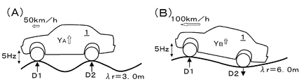
YA=(∂Y/∂D1)D1A+(∂Y/∂D2)D2A …(2)
YB=(∂Y/∂D1)D1B+(∂Y/∂D2)D2B
が得られ、これにより、上記二つの式を、連立方程式として、(∂Y/∂D1)と(∂Y/∂D2)とについて解くことが可能となり、周波数5Hzに於ける伝達関数(∂Y/∂D1)と(∂Y/∂D2)が得られることとなる。即ち、多数の異なる波長の変位の組合せとなる路面に於いて、車両を種々の異なる車速にて走行させて、振動計測を行うことにより、各周波数に於いて複数の振動データ(振動Yと入力成分Diとの組)が取得できることとなり、各振動入力に対する伝達関数が算出されることとなる。
上記の振動解析装置を用いて、本発明による振動解析は、下記の如く実行されてよい。
(a)振動計測処理
本発明による振動解析の振動計測処理に於いては、既に触れた如く、実際に道路上にて車両を走行させて路面高さの変位DL、DRと車体にて発生する振動の特性を表す加速度値Y、X1~4(振動特性値)、AL、AR(振動入力値の算出に利用される加速度値)とが逐次的に計測される。かかる振動計測のための車両の実路走行に於いて、振動の周波数特性をできるだけ広い範囲にて且つ細かく取得するために、車両の走行中にできるだけ多くの異なる周波数の振動が車体へ入力されるべきである。そこで、計測のための道路(試験用コース)は、できるだけ多くの異なる波長にて路面の高さが変位するよう構成されていることが好ましい。具体的には、一つの態様として、図3(A)に示されている如く、路面高さがステップ状に変位する道路が採用されてよい。ステップ状変位は、図示の如く、正弦波にて分解すると、多数の異なる波長の変位の組合せとなるので、その上を車輪が通過すると、多数の異なる周波数の振動が入力されることとなる。また、別の態様として、図3(B)に例示されている如く、多数の異なる波長の変位の組合せから成るランダムに路面高さが変位する道路が採用されてもよい。なお、かかるランダム路の方が、車両が通常走行する路面に近いこととなる。
既に触れた如く、本発明の車両の振動解析では、式(1)の如く、車体の振動Yが、振動入力値として車輪に於ける路面の変位成分Diに起因して発生するとのモデルに基づいて実行される。4輪車両の場合、車輪に於ける路面変位成分Diとしては、前後左右輪の上下方向の変位の組、或いは、左右前輪同相入力、左右後輪同相入力、左右前輪逆相入力及び左右後輪逆相入力の組などであってよい。例えば、左右前輪同相入力D1(s)、左右後輪同相入力D2(s)、左右前輪逆相入力D3(s)及び左右後輪逆相入力D4(s)の組を振動入力値として用いる場合、各入力値は、左右輪の通過位置の車体に対する路面変位値DL、DR及び左右輪通過位置上下加速度値AL、ARの周波数sを変数としたラプラス変換された値と車速Uとを用いて、下記の如く算出される。

かくして、(振動入力値の数以上の)振動特性値Y(s)と振動入力値D1(s)~D4(s)とデータの組が得られると、重回帰分析の理論に従って、各振動入力値Di(s)に対する振動特性値Y(s)の伝達関数∂Y/∂Di(s)が算出される。具体的には、振動特性値Y(s)と振動入力値Di(s)との関係が式(1)により与えられるモデルに於いて多変数の最小自乗法を用いて、伝達関数は、下記の式により、算出されてよい。
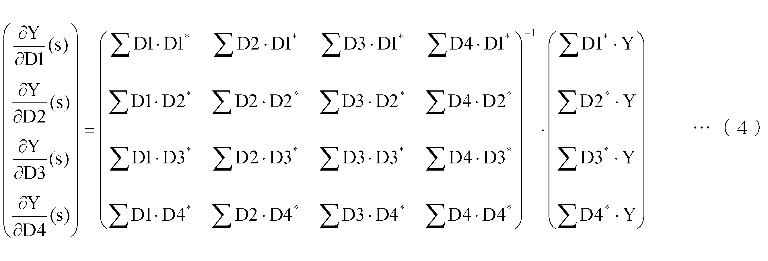
かくして、伝達関数∂Y/∂Di(s)が決定されると、各振動入力値Diによる振動Yiの大きさが下記の式により算出される。

上記の如く伝達関数が決定されると、任意の路面条件及び/又は車速条件、即ち、振動計測を実行した路面条件又は車速条件とは異なる路面条件及び/又は車速条件に於いて発生されるべき振動レベルY’の大きさの推定が可能となる(異なる路面条件及び/又は車速条件への換算)。具体的には、任意の路面条件及び/又は車速条件に於ける振動レベルY’の大きさは、下記の式により与えられる。

本発明の振動解析に於いては、振動入力値として、各輪の路面変位成分Diに代えて、各輪のばね下上下加速度値Xiを用いても、上記と同様に振動Yの伝達関数が算出される。即ち、式(1)に対応するモデルとして、
Y=b1・X1+b2・X2+b3・X3+b4・X4 …(7)
を想定すると(biは、ばね下上下加速度値Xiに対する振動Yの伝達関数(∂Y/∂Xi)である。)、各輪のばね下上下加速度値Xi(s)に対する振動Y(s)の伝達関数は、式(4)と同様に、下記の式により与えられる。
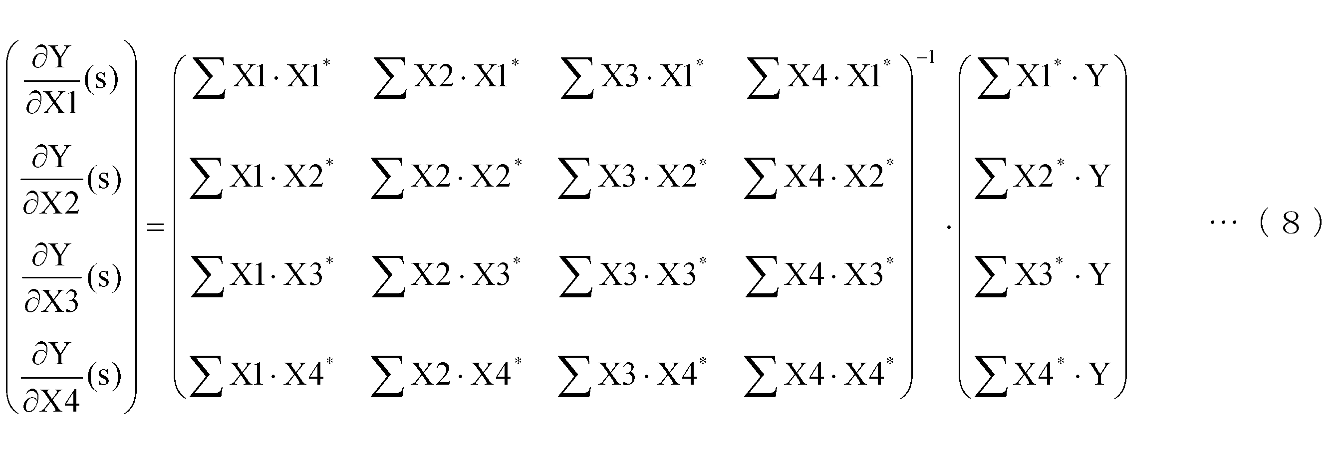


上記に説明した本発明の振動解析の方法に従って、伝達関数の算出、振動レベルの検出等の実験を行い、本発明の有効性を検証した。なお、以下の実験例は、本発明の有効性を例示するものであって、本発明の範囲を限定するものではないことは理解されるべきである。
図4は、試験用コースに於いて車速30km/h、40km/h、50km/h、60km/h、70km/hにて4輪車両の走行と振動計測を行って得られた路面変位成分に対するばね上上下加速度値の伝達関数とばね下上下加速度値の伝達関数の周波数特性の例を示している。路面変位成分は、式(3)により算出し、伝達関数は、式(4)により算出した。図に於いては、前輪同相入力に対するばね上加速度の伝達関数∂Ys/∂D1、前輪同相入力に対する前輪ばね下加速度の伝達関数∂Yuf/∂D1、後輪同相入力に対するばね上加速度の伝達関数∂Ys/∂D2、後輪同相入力に対する前輪ばね下加速度の伝達関数∂Yuf/∂D2のゲインと位相とがそれぞれ示されている。同図のゲインの周波数特性を参照して理解される如く、ばね上加速度の伝達関数に於いては、ばね上共振周波数にて極大が見られ、ばね下加速度の伝達関数に於いては、ばね下共振周波数にて極大が見られた。伝達関数の極大は、その周波数に於いて、振動伝達が極大となることを示している。この結果は、本発明の振動解析技術によれば、車両のばね上共振、ばね下共振などの共振点の検出ができる安定した伝達関数の検出が可能であることを示唆している。
図5は、本発明の振動解析技術に従って、各路面入力成分に対する車両の前後加速度の伝達関数を算出した後、各路面入力成分による前後加速度の振動の大きさの周波数スペクトルを個別に算出した例を示している。なお、車両の走行と振動の計測は、図4の場合と同様に実行した。路面変位成分は、式(3)により算出し、伝達関数は、式(4)により算出した。また、振動の大きさは、路面入力成分毎に式(5)により算出した。同図に於いて、「変更前」と付された値は、或る試験車両について得られた値であり、「変更後」と付された値は、かかる試験車両に於いてリアサスペンションの側面視に於ける配置を変更した場合に於いて得られた値である。同図の、特に(C)を参照して、図中矢印にて示されている如く、後輪同相入力による振動の大きさの「変更前」と「変更後」周波数スペクトルに於いて、有意な差異が観察された。このことは、リアサスペンションの配置の変更により、後輪同相入力による振動に対する寄与が変化したことを示している。
本発明の振動解析技術に従って、或る試験用コースに於いて計測された振動データを用いて算出された各路面変位入力に対する振動の伝達関数を用いて、別の路面条件及び車速条件に於いて車両を走行させた場合に得られるべき振動レベルを算出し、その別の路面条件及び車速条件に於いて車両を実際に走行させた場合に得られた振動レベルと比較した。伝達関数の算出は、試験用コースAに於いて種々の車速での車両走行及び振動計測を行って得られた結果から、式(3)、(4)を用いて算出した。そして、算出された伝達関数を用いて、式(6)を用いて、別の試験用コースBに於いて或る車速Uにて走行させた場合に得られるべき振動レベルを算出した。図7は、本発明の振動解析技術に従って試験用コースAに於ける車両走行及び振動計測から得られた伝達関数を用いて算出された試験用コースBに於いて車速Uにて走行させた場合に得られるべきドライバ席の上下加速度、前後加速度及び左右加速度の振動の周波数スペクトル(「換算結果」)と、試験用コースBに於いて実際に車速Uにて車両を走行させた場合に得られたドライバ席の上下加速度、前後加速度及び左右加速度の振動の周波数スペクトル(「実測結果」)とが示されている。図7を参照して理解される如く、ドライバ席の上下加速度、前後加速度及び左右加速度の振動の周波数スペクトルのいずれの場合も、「換算結果」と「実測結果」とは、良好に一致した。このことは、本発明の振動解析技術により算出された伝達関数を用いて、任意の路面条件及び/又は車速条件に於いて生ずる振動レベルが推定可能であることを示唆している。
本発明の振動解析技術に従って、或る試験用コースに於いて車両を走行させた場合のばね下上下加速度値を振動入力値として用いて車体振動の伝達関数を算出し、かかる伝達関数を用いて別の路面条件及び車速条件に於いて車両を走行させた場合に得られるべき振動レベルを算出し、その別の路面条件及び車速条件に於いて車両を走行させた場合に実際に得られた振動レベルと比較した。伝達関数の算出は、試験用コースAに於いて種々の車速での車両走行及び振動計測を行って得られた各輪ばね下上下加速度値とばね上加速度値の結果から式(8)を用いて算出した。そして、算出された伝達関数を用いて、式(10)を用いて、別の試験用コースBに於いて或る車速Uにて走行させた場合に得られるべき振動レベルを算出した。図8は、本発明の振動解析技術に従って試験用コースAに於ける車両走行及び振動計測から得られた伝達関数を用いて算出された試験用コースBに於いて或る車速Uにて走行させた場合に得られるべきドライバ席の上下加速度、前後加速度及び左右加速度の振動の周波数スペクトル(「換算結果」)と、試験用コースBに於いて実際に車速Uにて車両を走行させた場合に得られたドライバ席の上下加速度、前後加速度及び左右加速度の振動の周波数スペクトル(「実測結果」)とが示されている。図8を参照して理解される如く、ドライバ席の上下加速度、前後加速度及び左右加速度の振動の周波数スペクトルのいずれの場合も、「換算結果」と「実測結果」とは、良好に一致した。このことは、本発明の振動解析技術により各輪のばね下上下加速度値を振動入力値として用いて算出された伝達関数によって、任意の路面条件及び/又は車速条件に於いて生ずる振動レベルが推定可能であることを示唆している。
Claims (11)
- 車両の振動解析方法であって、
前記車両を該車両の進行方向に沿って種々の波長にて高さが変位する路面上にて走行させる過程と、
前記路面上にて走行中の前記車両の車体の部位に於ける振動特性値を計測する過程と、
前記車体の部位に於ける振動特性値を惹起する少なくとも二つの振動入力値を取得する過程と、
前記車体の部位に於ける振動特性値を目的変数として用い、前記少なくとも二つの振動入力値を説明変数として用いて、重回帰分析により偏回帰係数として前記少なくとも二つの振動入力値の各々に対する前記車体の部位に於ける振動特性値の伝達関数を算出する過程と
を含む方法。 - 請求項1の方法であって、前記車両を該車両の進行方向に沿って種々の波長にて高さが変位する路面上にて走行させる過程に於いて、異なる車速にて前記車両を走行させる方法。
- 請求項1又は2の方法であって、前記少なくとも二つの振動入力値が前記車両の各輪に於ける路面変位の関数であり、前記車体の部位に於ける振動特性値が前記車両のばね上加速度値又はばね下加速度値である方法。
- 請求項1又は2の方法であって、前記少なくとも二つの振動入力値が、左右前輪にて同相に変位する路面変位成分と、左右後輪にて同相に変位する路面変位成分と、左右前輪にて逆相に変位する路面変位成分と、左右後輪にて逆相に変位する路面変位成分とを含む方法。
- 請求項1又は2の方法であって、前記少なくとも二つの振動入力値が前記車両の各輪に於けるばね下加速度値であり、前記車体の部位に於ける振動特性値が前記車両のばね上加速度である方法。
- 請求項1の方法であって、前記少なくとも二つの振動入力値のうちの一つと、それに対応する前記伝達関数とを用いて、前記少なくとも二つの振動入力値のうちの一つにより惹起される前記車体の部位に於ける振動特性値の振動の大きさを算出する過程を更に含む方法。
- 請求項1の方法であって、前記伝達関数を用いて、該伝達関数の算出に用いた前記車体の部位に於ける振動特性値の計測及び前記振動入力値の取得を行った際に走行した路面とは異なる路面にて前記車両を走行させた場合に得られるべき前記車体の部位に於ける振動特性値を推定する過程を更に含む方法。
- 請求項1の方法であって、前記伝達関数を用いて、該伝達関数の算出に用いた前記車体の部位に於ける振動特性値の計測及び前記振動入力値の取得を行った際の車速とは異なる車速にて前記車両を走行させた場合に得られるべき前記車体の部位に於ける振動特性値を推定する過程を更に含む方法。
- 請求項1の方法であって、前記路面がランダムに高さが変位する路面である方法。
- 請求項1の方法であって、前記路面がステップ状に高さが変位する路面である方法。
- 車両の振動解析装置であって、前記車両を該車両の進行方向に沿って種々の波長にて高さが変位する路面上にて走行させる間に於いて前記車両の車体の部位に於ける振動特性値を計測する振動特性値計測部と、前記車体の部位に於ける振動特性値を惹起する少なくとも二つの振動入力値を取得する振動入力値取得部と、前記車体の部位に於ける振動特性値を目的変数として用い、前記少なくとも二つの振動入力値を説明変数として用いて、重回帰分析により偏回帰係数として前記少なくとも二つの振動入力値の各々に対する前記車体の部位に於ける振動特性値の伝達関数を算出する伝達関数算出部とを含む装置。
Priority Applications (5)
| Application Number | Priority Date | Filing Date | Title |
|---|---|---|---|
| CN201380071136.5A CN104937388A (zh) | 2013-01-23 | 2013-01-23 | 车辆的振动解析方法及振动解析装置 |
| US14/654,674 US20150308926A1 (en) | 2013-01-23 | 2013-01-23 | Vibration analysis method and vibration analysis device of vehicle |
| PCT/JP2013/051266 WO2014115259A1 (ja) | 2013-01-23 | 2013-01-23 | 車両の振動解析方法及び振動解析装置 |
| JP2014558328A JP6090336B2 (ja) | 2013-01-23 | 2013-01-23 | 車両の振動解析方法及び振動解析装置 |
| DE112013006483.9T DE112013006483T5 (de) | 2013-01-23 | 2013-01-23 | Vibrationsanalyseverfahren und Vibrationsanalysevorrichtung eines Fahrzeugs |
Applications Claiming Priority (1)
| Application Number | Priority Date | Filing Date | Title |
|---|---|---|---|
| PCT/JP2013/051266 WO2014115259A1 (ja) | 2013-01-23 | 2013-01-23 | 車両の振動解析方法及び振動解析装置 |
Publications (1)
| Publication Number | Publication Date |
|---|---|
| WO2014115259A1 true WO2014115259A1 (ja) | 2014-07-31 |
Family
ID=51227076
Family Applications (1)
| Application Number | Title | Priority Date | Filing Date |
|---|---|---|---|
| PCT/JP2013/051266 Ceased WO2014115259A1 (ja) | 2013-01-23 | 2013-01-23 | 車両の振動解析方法及び振動解析装置 |
Country Status (5)
| Country | Link |
|---|---|
| US (1) | US20150308926A1 (ja) |
| JP (1) | JP6090336B2 (ja) |
| CN (1) | CN104937388A (ja) |
| DE (1) | DE112013006483T5 (ja) |
| WO (1) | WO2014115259A1 (ja) |
Cited By (6)
| Publication number | Priority date | Publication date | Assignee | Title |
|---|---|---|---|---|
| JP2017122612A (ja) * | 2016-01-06 | 2017-07-13 | 株式会社エー・アンド・デイ | 車両特性解析方法及び装置 |
| JP2018538519A (ja) * | 2015-10-16 | 2018-12-27 | ポリテクニコ ディ バーリ | 道路車両又は鉄道車両のモーダルパラメーターを求める方法及び道路プロファイル又はレールプロファイルの間接的な特徴付けの方法 |
| WO2019229815A1 (ja) * | 2018-05-28 | 2019-12-05 | 株式会社日立製作所 | 鉄道車両システム |
| JP2020160075A (ja) * | 2020-06-02 | 2020-10-01 | パイオニア株式会社 | 段差検出装置 |
| JP2022165496A (ja) * | 2021-04-20 | 2022-11-01 | Kyb株式会社 | 機械学習を用いた振動減衰装置の特性分析装置、特性分析方法及びプログラム |
| US20240035824A1 (en) * | 2020-12-10 | 2024-02-01 | National Institute Of Advanced Industrial Science And Technology | Information processing device, information processing method, and non-transitory computer readable medium |
Families Citing this family (10)
| Publication number | Priority date | Publication date | Assignee | Title |
|---|---|---|---|---|
| CN105510057B (zh) * | 2016-01-25 | 2019-01-01 | 中国汽车技术研究中心 | 一种自由状态下车轮力传递函数测试方法及装置 |
| DE102018113289B4 (de) * | 2017-11-09 | 2025-10-23 | Grammer Aktiengesellschaft | System und Verfahren zum Bestimmen von Ganzkörper-Vibrationen |
| CN108801451B (zh) * | 2018-08-09 | 2019-12-17 | 安徽江淮汽车集团股份有限公司 | 一种车辆座椅腰部振动的检查方法 |
| DE102019004087A1 (de) | 2019-06-08 | 2020-01-02 | Daimler Ag | Verfahren und Vorrichtung zur Erfassung von Vibrationen während der Fahrt |
| US12517010B2 (en) * | 2020-05-15 | 2026-01-06 | Deere & Company | Fault detection technique for a bearing |
| CN112949117B (zh) * | 2021-02-02 | 2022-08-12 | 天津城建大学 | 基于多维度参数的沥青路面三向应变分析方法 |
| US12320727B2 (en) * | 2021-08-20 | 2025-06-03 | Honda Motor Co., Ltd. | Vehicle vibration method and vehicle vibration device |
| CN114858491B (zh) * | 2022-04-22 | 2024-05-17 | 重庆长安汽车股份有限公司 | 一种车辆过减速带时冲击余振的客观测评方法 |
| IT202300018522A1 (it) * | 2023-09-08 | 2025-03-08 | Stellantis Europe Spa | Procedimento e sistema per una valutazione oggettiva della percezione, da parte del guidatore di un autoveicolo, del movimento vibratorio indotto dal traballamento del motore dell’autoveicolo |
| JP2026048214A (ja) * | 2024-09-05 | 2026-03-17 | トヨタ自動車株式会社 | 制御マップの管理方法及び管理システム |
Citations (7)
| Publication number | Priority date | Publication date | Assignee | Title |
|---|---|---|---|---|
| JPH03123826A (ja) * | 1989-09-30 | 1991-05-27 | F Heinrich Lehn | 走行運転中に自動車の車輪システムの振動を監視する方法及び装置 |
| JP2000088697A (ja) * | 1998-09-11 | 2000-03-31 | Yokohama Rubber Co Ltd:The | 車両振動計測装置 |
| JP2000121506A (ja) * | 1998-10-20 | 2000-04-28 | Kawasaki Heavy Ind Ltd | 車両における乗り心地評価方法と装置 |
| JP2007155525A (ja) * | 2005-12-06 | 2007-06-21 | Denso Corp | タイヤ空気圧検出装置 |
| JP2007309652A (ja) * | 2006-05-16 | 2007-11-29 | Yokohama Rubber Co Ltd:The | タイヤ騒音試験方法 |
| JP2009097973A (ja) * | 2007-10-16 | 2009-05-07 | Toyota Motor Corp | 車両の振動解析方法及び装置 |
| JP2010095135A (ja) * | 2008-10-16 | 2010-04-30 | Toyota Motor Corp | 車輪振動抽出装置及び路面状態推定装置 |
Family Cites Families (9)
| Publication number | Priority date | Publication date | Assignee | Title |
|---|---|---|---|---|
| JP3098425B2 (ja) * | 1996-05-22 | 2000-10-16 | 株式会社豊田中央研究所 | 車両のばね上ばね下相対速度算出装置 |
| FR2819589A1 (fr) * | 2001-01-12 | 2002-07-19 | Michelin Soc Tech | Methode de prevision du confort a l'interieur d'un vehicule equipe d'un ensemble monte presentant des non uniformes |
| US7333882B2 (en) * | 2004-02-12 | 2008-02-19 | Hitachi, Ltd. | Suspension control apparatus |
| JP4935757B2 (ja) * | 2008-05-27 | 2012-05-23 | トヨタ自動車株式会社 | 車両用サスペンションシステム |
| DE102008002484A1 (de) * | 2008-06-17 | 2009-12-24 | Robert Bosch Gmbh | Verfahren zum Prüfen eines Schwingungsdämpfers eines Kraftfahrzeugs im eingebauten Zustand sowie Schwingungsdämpfer-Prüfsystem für ein Kraftfahrzeug |
| CN101498615B (zh) * | 2009-01-16 | 2010-09-01 | 清华大学 | 电动式道路模拟振动台 |
| JP5463263B2 (ja) * | 2009-11-30 | 2014-04-09 | 日立オートモティブシステムズ株式会社 | 車両用サスペンション制御装置 |
| EP2511111B1 (en) * | 2009-12-11 | 2015-06-10 | Toyota Jidosha Kabushiki Kaisha | Vehicle control device |
| CN102205781B (zh) * | 2010-03-31 | 2015-04-01 | 日立汽车系统株式会社 | 悬架控制装置及车辆控制装置 |
-
2013
- 2013-01-23 US US14/654,674 patent/US20150308926A1/en not_active Abandoned
- 2013-01-23 WO PCT/JP2013/051266 patent/WO2014115259A1/ja not_active Ceased
- 2013-01-23 JP JP2014558328A patent/JP6090336B2/ja not_active Expired - Fee Related
- 2013-01-23 DE DE112013006483.9T patent/DE112013006483T5/de not_active Withdrawn
- 2013-01-23 CN CN201380071136.5A patent/CN104937388A/zh active Pending
Patent Citations (7)
| Publication number | Priority date | Publication date | Assignee | Title |
|---|---|---|---|---|
| JPH03123826A (ja) * | 1989-09-30 | 1991-05-27 | F Heinrich Lehn | 走行運転中に自動車の車輪システムの振動を監視する方法及び装置 |
| JP2000088697A (ja) * | 1998-09-11 | 2000-03-31 | Yokohama Rubber Co Ltd:The | 車両振動計測装置 |
| JP2000121506A (ja) * | 1998-10-20 | 2000-04-28 | Kawasaki Heavy Ind Ltd | 車両における乗り心地評価方法と装置 |
| JP2007155525A (ja) * | 2005-12-06 | 2007-06-21 | Denso Corp | タイヤ空気圧検出装置 |
| JP2007309652A (ja) * | 2006-05-16 | 2007-11-29 | Yokohama Rubber Co Ltd:The | タイヤ騒音試験方法 |
| JP2009097973A (ja) * | 2007-10-16 | 2009-05-07 | Toyota Motor Corp | 車両の振動解析方法及び装置 |
| JP2010095135A (ja) * | 2008-10-16 | 2010-04-30 | Toyota Motor Corp | 車輪振動抽出装置及び路面状態推定装置 |
Non-Patent Citations (2)
| Title |
|---|
| HIROSHI IGUCHI ET AL.: "Contribution Analysis of Body and Seats on Riding Comfort", SOCIETY OF AUTOMOTIVE ENGINEERS OF JAPAN 2007 NEN SHUKI TAIKAI GAKUJUTSU KOENKAI ZENSATSUSHU, NO.104-07, THE SOCIETY OF AUTOMOTIVE ENGINEERS OF JAPAN, no. 104-07, 17 October 2007 (2007-10-17), pages 13 - 18 * |
| SHINGO KOMURA ET AL.: "Analysis of Roll and Lateral Vehicle Behavior by Road Input", SOCIETY OF AUTOMOTIVE ENGINEERS OF JAPAN 2007 NEN SHUKI TAIKAI GAKUJUTSU KOENKAI ZENSATSUSHU, NO.123-07, THE SOCIETY OF AUTOMOTIVE ENGINEERS OF JAPAN, no. 123-07, 17 October 2007 (2007-10-17), pages 7 - 12 * |
Cited By (8)
| Publication number | Priority date | Publication date | Assignee | Title |
|---|---|---|---|---|
| JP2018538519A (ja) * | 2015-10-16 | 2018-12-27 | ポリテクニコ ディ バーリ | 道路車両又は鉄道車両のモーダルパラメーターを求める方法及び道路プロファイル又はレールプロファイルの間接的な特徴付けの方法 |
| JP2017122612A (ja) * | 2016-01-06 | 2017-07-13 | 株式会社エー・アンド・デイ | 車両特性解析方法及び装置 |
| WO2019229815A1 (ja) * | 2018-05-28 | 2019-12-05 | 株式会社日立製作所 | 鉄道車両システム |
| JPWO2019229815A1 (ja) * | 2018-05-28 | 2021-05-13 | 株式会社日立製作所 | 鉄道車両システム |
| JP2020160075A (ja) * | 2020-06-02 | 2020-10-01 | パイオニア株式会社 | 段差検出装置 |
| US20240035824A1 (en) * | 2020-12-10 | 2024-02-01 | National Institute Of Advanced Industrial Science And Technology | Information processing device, information processing method, and non-transitory computer readable medium |
| JP2022165496A (ja) * | 2021-04-20 | 2022-11-01 | Kyb株式会社 | 機械学習を用いた振動減衰装置の特性分析装置、特性分析方法及びプログラム |
| JP7634838B2 (ja) | 2021-04-20 | 2025-02-25 | カヤバ株式会社 | 機械学習を用いた振動減衰装置の特性分析装置、特性分析方法及びプログラム |
Also Published As
| Publication number | Publication date |
|---|---|
| CN104937388A (zh) | 2015-09-23 |
| DE112013006483T5 (de) | 2015-10-29 |
| JP6090336B2 (ja) | 2017-03-08 |
| JPWO2014115259A1 (ja) | 2017-01-19 |
| US20150308926A1 (en) | 2015-10-29 |
Similar Documents
| Publication | Publication Date | Title |
|---|---|---|
| JP6090336B2 (ja) | 車両の振動解析方法及び振動解析装置 | |
| JP5504912B2 (ja) | タイヤの使用条件評価方法及び装置、並びにタイヤの摩耗予測方法及び装置 | |
| JP4967981B2 (ja) | 車両の振動解析方法及び装置 | |
| CN107933559A (zh) | 用于在车辆中确定道路特性的方法和系统 | |
| CN102797202A (zh) | 基于观测器的轨道横向不平顺检测方法 | |
| WO2012049810A1 (ja) | タイヤ状態検出装置およびタイヤ状態検出方法 | |
| CN111976731B (zh) | 基于车辆频域响应的路面不平度识别方法 | |
| KR20130063811A (ko) | 노면 거칠기 측정장치 및 그의 신호처리방법 그리고 그를 이용한 시스템 | |
| CN106461507A (zh) | 车辆测试装置、车辆测试方法以及车辆测试装置用程序 | |
| JP7595494B2 (ja) | 摩耗量推定システム、演算モデル生成システムおよび摩耗量推定方法 | |
| JP6535208B2 (ja) | 振動解析モデルの構造同定装置及びその同定方法 | |
| CN116698332B (zh) | 基于试验过程的低频抖动激励源识别方法及装置 | |
| JP2002031566A (ja) | 車重計測装置 | |
| Zeitvogel et al. | Holistic vehicle parametrization on a handling roadway | |
| CN104048834B (zh) | 用于车辆的侧向滑动测试的系统和方法 | |
| JP4845681B2 (ja) | タイヤの振動評価方法 | |
| JP6260477B2 (ja) | 振動解析装置及び振動解析方法 | |
| KR101365366B1 (ko) | 타이어 핸들링 성능 측정장치 및 측정방법 | |
| JP7355628B2 (ja) | タイヤの高速直進安定性を評価するシステム、方法及びプログラム | |
| JP2712537B2 (ja) | 路面計測法 | |
| JPWO2018011894A1 (ja) | 検測装置および検測方法 | |
| JP5160734B2 (ja) | 車軸多分力計測方法 | |
| JP7783033B2 (ja) | タイヤ摩耗性能値の算出方法、システム、及びプログラム | |
| Radonjić et al. | An approach to vehicle research | |
| Varunjikar et al. | Multi-body vehicle dynamics simulation based on measured 3D terrain data |
Legal Events
| Date | Code | Title | Description |
|---|---|---|---|
| 121 | Ep: the epo has been informed by wipo that ep was designated in this application |
Ref document number: 13872325 Country of ref document: EP Kind code of ref document: A1 |
|
| ENP | Entry into the national phase |
Ref document number: 2014558328 Country of ref document: JP Kind code of ref document: A |
|
| WWE | Wipo information: entry into national phase |
Ref document number: 14654674 Country of ref document: US |
|
| WWE | Wipo information: entry into national phase |
Ref document number: 112013006483 Country of ref document: DE Ref document number: 1120130064839 Country of ref document: DE |
|
| 122 | Ep: pct application non-entry in european phase |
Ref document number: 13872325 Country of ref document: EP Kind code of ref document: A1 |