WO2014108953A1 - Stérilisateur ultraviolet - Google Patents
Stérilisateur ultraviolet Download PDFInfo
- Publication number
- WO2014108953A1 WO2014108953A1 PCT/JP2013/006970 JP2013006970W WO2014108953A1 WO 2014108953 A1 WO2014108953 A1 WO 2014108953A1 JP 2013006970 W JP2013006970 W JP 2013006970W WO 2014108953 A1 WO2014108953 A1 WO 2014108953A1
- Authority
- WO
- WIPO (PCT)
- Prior art keywords
- ultraviolet
- plate
- sealed space
- outer peripheral
- transmitting plate
- Prior art date
Links
- VYPSYNLAJGMNEJ-UHFFFAOYSA-N Silicium dioxide Chemical compound O=[Si]=O VYPSYNLAJGMNEJ-UHFFFAOYSA-N 0.000 claims abstract description 43
- 238000007789 sealing Methods 0.000 claims abstract description 30
- 238000001514 detection method Methods 0.000 claims abstract description 12
- 230000002093 peripheral effect Effects 0.000 claims description 62
- 238000003825 pressing Methods 0.000 claims description 25
- 230000001954 sterilising effect Effects 0.000 claims description 16
- 238000004659 sterilization and disinfection Methods 0.000 claims description 15
- 239000000463 material Substances 0.000 abstract description 4
- 230000005540 biological transmission Effects 0.000 description 14
- 238000000034 method Methods 0.000 description 9
- QSHDDOUJBYECFT-UHFFFAOYSA-N mercury Chemical compound [Hg] QSHDDOUJBYECFT-UHFFFAOYSA-N 0.000 description 7
- 229910052753 mercury Inorganic materials 0.000 description 7
- 238000004806 packaging method and process Methods 0.000 description 4
- 229920001971 elastomer Polymers 0.000 description 3
- 239000011521 glass Substances 0.000 description 3
- 239000005060 rubber Substances 0.000 description 3
- 238000002834 transmittance Methods 0.000 description 3
- PPBRXRYQALVLMV-UHFFFAOYSA-N Styrene Chemical compound C=CC1=CC=CC=C1 PPBRXRYQALVLMV-UHFFFAOYSA-N 0.000 description 2
- 230000005856 abnormality Effects 0.000 description 2
- 238000005336 cracking Methods 0.000 description 2
- 230000001678 irradiating effect Effects 0.000 description 2
- 238000012423 maintenance Methods 0.000 description 2
- 239000011347 resin Substances 0.000 description 2
- 229920005989 resin Polymers 0.000 description 2
- YCKRFDGAMUMZLT-UHFFFAOYSA-N Fluorine atom Chemical compound [F] YCKRFDGAMUMZLT-UHFFFAOYSA-N 0.000 description 1
- 229920000459 Nitrile rubber Polymers 0.000 description 1
- 239000004809 Teflon Substances 0.000 description 1
- 229920006362 Teflon® Polymers 0.000 description 1
- 230000002159 abnormal effect Effects 0.000 description 1
- 239000000853 adhesive Substances 0.000 description 1
- 230000001070 adhesive effect Effects 0.000 description 1
- 239000003795 chemical substances by application Substances 0.000 description 1
- 239000012141 concentrate Substances 0.000 description 1
- 238000011109 contamination Methods 0.000 description 1
- 239000000112 cooling gas Substances 0.000 description 1
- 230000004069 differentiation Effects 0.000 description 1
- 229910052731 fluorine Inorganic materials 0.000 description 1
- 239000011737 fluorine Substances 0.000 description 1
- 239000005003 food packaging material Substances 0.000 description 1
- 239000007789 gas Substances 0.000 description 1
- 239000011261 inert gas Substances 0.000 description 1
- 230000007257 malfunction Effects 0.000 description 1
- 238000004519 manufacturing process Methods 0.000 description 1
- 229910001507 metal halide Inorganic materials 0.000 description 1
- 150000005309 metal halides Chemical class 0.000 description 1
- 238000012856 packing Methods 0.000 description 1
- 229920006254 polymer film Polymers 0.000 description 1
- 239000010453 quartz Substances 0.000 description 1
- 229920002379 silicone rubber Polymers 0.000 description 1
- 239000004945 silicone rubber Substances 0.000 description 1
Images


Classifications
-
- B—PERFORMING OPERATIONS; TRANSPORTING
- B65—CONVEYING; PACKING; STORING; HANDLING THIN OR FILAMENTARY MATERIAL
- B65B—MACHINES, APPARATUS OR DEVICES FOR, OR METHODS OF, PACKAGING ARTICLES OR MATERIALS; UNPACKING
- B65B55/00—Preserving, protecting or purifying packages or package contents in association with packaging
- B65B55/02—Sterilising, e.g. of complete packages
- B65B55/04—Sterilising wrappers or receptacles prior to, or during, packaging
- B65B55/08—Sterilising wrappers or receptacles prior to, or during, packaging by irradiation
-
- A—HUMAN NECESSITIES
- A61—MEDICAL OR VETERINARY SCIENCE; HYGIENE
- A61L—METHODS OR APPARATUS FOR STERILISING MATERIALS OR OBJECTS IN GENERAL; DISINFECTION, STERILISATION OR DEODORISATION OF AIR; CHEMICAL ASPECTS OF BANDAGES, DRESSINGS, ABSORBENT PADS OR SURGICAL ARTICLES; MATERIALS FOR BANDAGES, DRESSINGS, ABSORBENT PADS OR SURGICAL ARTICLES
- A61L2/00—Methods or apparatus for disinfecting or sterilising materials or objects other than foodstuffs or contact lenses; Accessories therefor
- A61L2/02—Methods or apparatus for disinfecting or sterilising materials or objects other than foodstuffs or contact lenses; Accessories therefor using physical phenomena
- A61L2/08—Radiation
- A61L2/10—Ultraviolet radiation
Definitions
- the present invention relates to an ultraviolet sterilizer that sterilizes food packaging materials by irradiating ultraviolet light (UV) through an ultraviolet transmissive plate, and more particularly to an ultraviolet sterilizer that can detect breakage of the ultraviolet transmissive plate. .
- UV ultraviolet light
- the high-pressure mercury type ultraviolet lamp has a problem that it has a short life because it is exposed to high heat, and has a problem that the transmittance of ultraviolet rays is greatly reduced as compared with the case of quartz glass alone.
- an ultraviolet transmissive plate such as a quartz glass plate is doubled in the lower opening of the housing, a sealed space is formed between these ultraviolet transmissive plates, and micro air is introduced into the sealed space or the sealed space.
- An object of the present invention is to provide an ultraviolet sterilizer capable of detecting a breakage of an ultraviolet transmission plate with higher accuracy while suppressing attenuation of ultraviolet rays by an ultraviolet transmission plate such as quartz glass.
- the present inventors have developed an ultraviolet sterilizer that can detect damage to an ultraviolet transmitting plate with higher accuracy while suppressing attenuation of ultraviolet rays by an ultraviolet transmitting plate such as quartz glass.
- an ultraviolet transmitting plate such as quartz glass.
- the ultraviolet ray transmitting plate is not disposed so as to be doubled so as to form a sealed space between the ultraviolet ray transmitting plates, but by forming a sealed space in the outer peripheral portion of one ultraviolet ray transmitting plate, It has been found that breakage of the ultraviolet transmission plate can be detected with higher accuracy while suppressing attenuation of ultraviolet rays by the transmission plate, and the present invention has been completed. That is, according to the present invention, since the ultraviolet ray transmitting plate can be single instead of being doubled, attenuation of ultraviolet rays by the ultraviolet ray transmitting plate can be suppressed, and a sealed space is formed on the outer periphery of the ultraviolet ray transmitting plate.
- the gauge pressure in the sealed space can be kept higher or lower while avoiding the possibility of damage to the ultraviolet transmitting plate, and as a result, when there is a fine crack due to some abnormality in the ultraviolet transmitting plate
- the amount of outflow or inflow of air in the sealed space increases, making it easy to detect the air flow in the sealed space with a flow meter, and detecting the breakage of the UV transmitting plate with higher accuracy.
- the present invention (1) an ultraviolet lamp; a housing that surrounds the ultraviolet lamp; an ultraviolet transmissive portion that is provided in a lower opening of the housing and includes an ultraviolet transmissive plate and a means for holding the ultraviolet transmissive plate; an air flow detecting means;
- the ultraviolet ray transmitting portion holding means has sealing means for forming a sealed space communicating with the air flow detecting means at one end in cooperation with an outer peripheral portion of the ultraviolet ray transmitting plate, and the air flow detecting means Is provided with an air pressure adjusting means and a flow meter for adjusting the air pressure in the sealed space, and the sealed space generated when the sealed state of the sealed space is released due to the damage of the ultraviolet transmitting plate.
- UV sterilizer characterized by detecting the flow of air with a flow meter, (2) The ultraviolet sterilizer according to (1) above, wherein the outer peripheral portion of the ultraviolet transmitting plate is an outer peripheral end surface or an outer peripheral edge of the ultraviolet transmitting plate, (3)
- the ultraviolet ray transmitting plate holding means includes a base plate fixed to the lower end of the side wall of the housing and a pressing plate fixed on the base plate.
- the sealing means is a means for directly sealing the outer base plate and the pressing plate on the outer peripheral end face of the ultraviolet transmitting plate and sealing the base plate and the pressing plate through the outer peripheral edge of the ultraviolet transmitting plate.
- the ultraviolet sterilizer according to (3) above, wherein the sealed space is formed along the outside of the outer peripheral end face of the ultraviolet transmissive plate, (5)
- the sealing means is means for sealing the base plate and the pressing plate through two predetermined intervals on the outer peripheral edge of the ultraviolet transmitting plate, and the sealed space is on the upper surface side of the outer peripheral edge of the ultraviolet transmitting plate.
- the ultraviolet sterilizer according to (3) characterized in that it is formed as a concave circumferential groove of a base plate corresponding to the pressing plate and / or the lower surface side, (6)
- the air pressure adjusting means is an air suction means for sucking air of a predetermined pressure from the sealed space and holding the sealed space in a negative pressure state.
- UV sterilizer according to any of the (8) The ultraviolet sterilizer according to any one of (1) to (7) above, wherein the ultraviolet transmitting plate is made of quartz glass.
- the present invention it is possible to form a sealed space in the outer peripheral portion of one ultraviolet transmitting plate instead of arranging the ultraviolet transmitting plates in a double manner and forming a sealed space between the ultraviolet transmitting plates.
- the gauge pressure in the sealed space can be kept higher or lower while avoiding the possibility of breakage of the transmission plate. As a result, even in the case where a minute crack occurs due to some abnormality in the ultraviolet transmission plate, The outflow amount or the inflow amount of air is increased, and the breakage of the ultraviolet transmitting plate can be detected with higher accuracy.
- the ultraviolet ray transmitting plate can be made single, the attenuation (illuminance loss) of the ultraviolet ray emitted from the ultraviolet lamp is reduced as compared with the case where the sealed space is formed by the double ultraviolet ray transmitting plate. In addition, the manufacturing cost can be reduced. Further, since the structure of the apparatus of the present invention is not so complicated, the present invention can be applied to various models at a low cost.
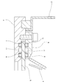
- FIG. 1 It is a schematic longitudinal cross-sectional view (front) of the ultraviolet sterilizer of this invention. It is an enlarged view of the part of A in FIG. It is the elements on larger scale of the ultraviolet sterilizer of this invention of another aspect.
- the ultraviolet sterilizer of the present invention includes: an ultraviolet lamp; a housing that surrounds the ultraviolet lamp; an ultraviolet transmissive portion that is provided in a lower opening of the housing and includes an ultraviolet transmissive plate and a means for holding the ultraviolet transmissive plate;
- the ultraviolet ray transmitting portion holding means has sealing means for forming a sealed space communicating with the air flow detecting means at one end in cooperation with the outer peripheral portion of the ultraviolet ray transmitting plate.
- the air flow detecting means includes an air pressure adjusting means for adjusting the air pressure in the sealed space and a flow meter, and when the sealed state of the sealed space is released due to breakage of the ultraviolet transmitting plate
- the outer peripheral edge and the outer peripheral edge of the overplate is the upper surface of the ultraviolet transmitting plate in the vicinity from the outer peripheral edge of the ultraviolet transmitting plate in a plan view (usually a region of 2 to 100 mm from the outer peripheral edge)
- region of a lower surface is said, and an outer peripheral end surface means the area
- the ultraviolet lamp a known ultraviolet lamp can be appropriately used in consideration of the ultraviolet transmittance of the ultraviolet transmitting portion, the necessary ultraviolet ray amount of the sterilization target, and the like.
- any UV lamp can be used regardless of the level of the vapor pressure in the lamp being lit, such as a low-pressure UV lamp, medium-pressure UV lamp, and high-pressure UV lamp.
- a high-pressure ultraviolet lamp such as a high-pressure mercury lamp or a metal halide lamp.
- the ultraviolet transmissive plate can be single, that is, a single sheet.
- the attenuation factor is low, it can be suitably used even with a low-pressure ultraviolet lamp or a medium-pressure ultraviolet lamp.
- a shape of the ultraviolet lamp used in the ultraviolet sterilization apparatus of the present invention from the viewpoint of securing a long sterilization time for the sterilization target to some extent, it is a long straight tube or an elongated U-shaped tube whose longitudinal direction is the movement direction of the sterilization target. It is preferable that the number thereof may be one or two or more.
- the housing is not particularly limited in shape and material as long as it encloses the ultraviolet lamp in the present invention and has an opening for the ultraviolet transmitting portion below, but for example, one of the six-sided rectangular parallelepiped shapes is ultraviolet-transmissive.
- the shape removed as the lower opening for the part can be suitably exemplified.
- the housing may be formed integrally with the holding means.
- the ultraviolet transmissive part disposed in the lower opening of the housing includes an ultraviolet transmissive plate and a means for holding the ultraviolet transmissive plate.
- the shape of the ultraviolet transmissive plate is not particularly limited, although it depends on the shape of the ultraviolet lamp, and is a plate shape such as a rectangle, square, circle or ellipse in a plan view, or a convex shape which can concentrate ultraviolet rays on the sterilization target. From the viewpoint of securing a long sterilization time for the sterilization target to some extent, the moving direction of the sterilization target is set to the longitudinal direction in accordance with the shape of the long linear tubular or long U-shaped ultraviolet lamp. A rectangular plate shape can be suitably exemplified.
- the thickness of the ultraviolet transmitting plate is not particularly limited as long as it can be sterilized by an ultraviolet lamp, but it is 0.5 to 15 mm in terms of the balance between the strength of the ultraviolet transmitting plate and the attenuation rate of ultraviolet rays by the ultraviolet transmitting plate. 2 to 7 mm is more preferable.
- the material of the ultraviolet ray transmitting plate is not particularly limited as long as it can transmit ultraviolet rays, but examples other than quartz glass include those described in JP-T-2005-519816 (Patent Document 3). Quartz glass is preferred because of its high transmittance.
- it is preferable to use one ultraviolet transmitting plate in the present invention it may be doubled as long as the attenuation rate of ultraviolet rays does not become too high.
- a sealed space can also be provided on the outer peripheral portion of the second ultraviolet transmitting plate, but it is not necessary to provide it.
- the ultraviolet transmissive plate can be held at its outer peripheral edge so as to irradiate the sterilization target by the ultraviolet lamp, and cooperates with the outer peripheral portion of the ultraviolet transmissive plate.
- the ultraviolet transmissive plate has a sealing means for forming a sealed space, and a concave groove for holding the outer peripheral edge of the UV transmitting plate is provided in three sides, and the UV transmitting plate is held from the other open end.
- a base plate lower holding plate
- a holding plate upper holding plate
- the base plate has an opening in the portion where the ultraviolet transmissive plate is arranged so that the ultraviolet lamp can irradiate the object to be sterilized, and the ultraviolet transmissive plate is held in cooperation with the holding plate at the opening edge.
- an opening edge portion on which the ultraviolet transmitting plate can be placed is formed in a concave step portion larger than the thickness of the ultraviolet transmitting plate.
- the opening has a shape substantially similar to the planar shape of the ultraviolet transmitting plate and smaller than the planar shape of the ultraviolet transmitting plate. A thing can be illustrated more suitably.
- the base plate opening may have an opening end at a position of 2 to 100 mm, preferably 5 to 50 mm inward from the outer peripheral end of the ultraviolet transmitting plate.
- an opening having an opening end at a position 30 mm inward from the outer peripheral end of a rectangular ultraviolet transmission plate 30 cm long and 60 cm wide becomes a rectangular shape having a length of 24 cm and a width of 54 cm.
- the holding plate has an opening in the portion where the ultraviolet transmissive plate is arranged so that the ultraviolet lamp can irradiate the object to be sterilized, and the ultraviolet transmissive plate is held in cooperation with the base plate at the opening edge.
- a preferable example is one that can press and hold the outer peripheral edge of the ultraviolet transmitting plate in cooperation with the base plate.
- a material that can press and hold the entire outer peripheral edge portion of the ultraviolet light transmitting plate in cooperation with the base plate can be more preferably exemplified.
- the holding plate opening can be exemplified by a shape that is substantially similar to the shape of the ultraviolet transmissive plate in plan view and smaller than the shape in plan view. Those having an opening end at a position of 2 to 100 mm, preferably 5 to 50 mm are preferable.
- a sealing agent such as a resin-based adhesive that can seal the opposing surfaces such as the base plate and the pressing plate directly or through an ultraviolet transmitting plate, or a holding means.
- a sealing agent such as a resin-based adhesive that can seal the opposing surfaces such as the base plate and the pressing plate directly or through an ultraviolet transmitting plate, or a holding means.
- an elastic body such as nitrile rubber, styrene rubber, silicone rubber, and fluorine rubber fitted into the concave circumferential groove are preferable, but sealing means using the elastic body is preferable for ease of assembly.
- the shape of the elastic body include an O-ring shape and a plate shape, and an O-ring-shaped elastic body (hereinafter referred to as an O-ring) is particularly preferable. In the case of using an O-ring, a better sealed state can be obtained if the diameter is slightly larger than the depth of the concave groove.
- FIGS. 1 and 2 A form (first sealing form; FIGS. 1 and 2) in which the base plate and the holding plate outside the outer peripheral end surface of the plate are directly sealed, and the base plate and the holding plate are sealed through the outer peripheral edge of the ultraviolet ray transmitting plate.
- the base plate and the pressing plate are sealed via two predetermined intervals on the upper surface side and the lower surface side of the outer peripheral edge portion of the ultraviolet transmitting plate, and the upper surface of the outer peripheral edge portion of the ultraviolet transmitting plate.
- the sealed space does not have to be formed over the entire circumference of the outer periphery of the UV transmitting plate, but from the viewpoint of detecting damage to the UV transmitting plate with higher accuracy, It is preferably formed in a tubular shape.
- One end of the sealed space is communicated with an air flow detection means through a port (opening) and a pipe.
- the port is a vacuum port when sucking air from the sealed space, and when air is introduced into the sealed space. Can be called a discharge port.
- the air flow detecting means is not particularly limited as long as it includes an air pressure adjusting means for adjusting the atmospheric pressure in the sealed space and a flow meter, and the air pressure adjusting means supplies air of a predetermined pressure to the sealed space.
- the sealed space can be held at a positive pressure or a negative pressure by introducing or sucking air of a predetermined pressure from the sealed space.
- air pressure adjusting means air supply means for introducing air of a predetermined pressure to keep the sealed space of the UV transmitting part in a positive pressure state, or sucking air to set the sealed space of the UV transmitting part in a negative pressure state.
- the air suction means (vacuum suction means) to be held in the container can be exemplified.
- the flow meter is provided in a pipe or the like between the air pressure adjusting means and the sealed space.
- the sealed space is sealed in accordance with the breakage of the ultraviolet transmitting plate. It is possible to detect the air flow in the sealed space that occurs when the state is released. It is preferable to arrange an electromagnetic valve that can open or close the pipe in the pipe between the air pressure adjusting means and the flow meter.
- an electromagnetic valve that can open or close the pipe in the pipe between the air pressure adjusting means and the flow meter.
- a regulator or a pressure switch that is preferably further arranged on the pipe is not necessary when the sealed space is held at a positive pressure.
- a regulator is a device for controlling the pressure supplied from the air supply means to a target pressure when the sealed space is held at a positive pressure, and the pressure switch is due to a malfunction of the regulator or the like. This is a switch for detecting an abnormal pressure and shutting off the air supply.
- Air means not only air but also all gases including inert gas.
- the gauge pressure in the sealed space (pressure notation with atmospheric pressure as the zero base point) can be set within a range of, for example, greater than 0 kPaG and less than or equal to 700 kPaG. From the viewpoint of detection with higher accuracy and from the viewpoint of safety of debris scattering due to positive pressure when the ultraviolet transmitting plate is broken, it is preferably in the range of 10 to 100 kPaG, and in the range of 10 to 50 kPaG. More preferred.
- the gauge pressure in the sealed space can be set within a range of, for example, less than 0 kPaG to ⁇ 101.3 kPaG, from the viewpoint of detecting the breakage of the ultraviolet transmission plate with higher accuracy. , Preferably in the range of ⁇ 50 to ⁇ 100 kPaG, more preferably in the range of ⁇ 90 to ⁇ 100 kPaG.
- the flow meter is not particularly limited as long as it can detect the air flow when the air flow is generated in the pipe.
- a flow meter having a minimum detection amount of about 0.05 to 0.5 L / min.
- the minimum detection flow rate is set so that detection can be performed when an air flow of 0.2 L / min or more occurs. It is preferable to do.
- a flow sensor flow sensor type flow meter
- FIG. 1 is a schematic cross-sectional view of the ultraviolet sterilizer of the present invention having the sealing means of the first embodiment
- FIG. 2 is an enlarged view of a portion A in FIG.
- FIG. 3 is the elements on larger scale of the ultraviolet sterilizer of this invention which has the sealing means of a 2nd aspect.
- the ultraviolet sterilizer of this type is provided in a U-tube type (single lamp type) ultraviolet lamp 3; a reflector 4; a housing 2 surrounding the ultraviolet lamp 3; and a lower opening of the housing 2.
- An ultraviolet transmitting part having a rectangular quartz glass 5 (ultraviolet transmitting plate) and a holding means for the quartz glass 5 provided with a base plate 1 and a pressing plate 6 fixed to the base plate 1 with screws; a vacuum pump (air Suction means), an air flow detecting means including a solenoid valve and a flow meter.
- the base plate 1 has a concave step for placing the quartz glass 5 and a quartz plate 5 at a substantially central portion than the quartz glass 5.
- quartz glass 5 When quartz glass 5 is placed on a horizontal surface of a concave step having a small similar rectangular opening, four surfaces of the outer peripheral end surface of the ultraviolet transmitting plate, the horizontal surface of the concave step, the vertical surface of the concave step, and the lower surface of the pressing plate 6 Tube composed of Enclosed space, i.e., in cooperation with the outer peripheral edge surface of the ultraviolet transmitting plate is configured along an outer peripheral end surface of ultraviolet transmitting plate, so that the tubular enclosed space communicating with the air flow detecting means is formed at one end.
- an O-ring 7 is provided between the pressing plate 6 and the base plate 1
- an O-ring 8 is provided between the pressing plate 6 and the ultraviolet transmission plate, and the base plate 1 and the ultraviolet transmission plate.
- the tubular sealed space communicates with the air flow detection means at one end via the vacuum port 10 and is formed when the sealed state of the tubular sealed space is released due to the breakage of the quartz glass 5.
- the air flow inside can be detected by a flow meter.
- the opening of the base plate 1 has an opening end at a position of 9.5 mm inward from the outer edge of the quartz glass 5, and the opening of the pressing plate 6 has an opening of 7 mm inward from the outer peripheral end of the quartz glass 5. Is the open end.
- the concave circumferential groove of the O-ring 7 is provided at a distance of about 3 mm from the outer peripheral end of the quartz glass 5, but can be provided at a distance of about 2.5 to 50 mm.
- the concave circumferential groove of the O-ring 9 is provided at a distance of about 2 mm from the outer peripheral end of the quartz glass 5, but may be provided at a distance of about 0.5 to 45 mm.
- the container is sterilized by the ultraviolet sterilizer (type I) of the present invention, for example, as follows. While the gable top type packaging container C is opened in the longitudinal direction with the upper part opened, ultraviolet rays irradiated from the ultraviolet lamp 3 (for example, a low-pressure mercury lamp) are large in size. A high illuminance is maintained by the reflecting plate 4, and the bottom of the packaging container C can be reliably irradiated and sterilized.
- the ultraviolet sterilizer (type I) of the present invention for example, as follows. While the gable top type packaging container C is opened in the longitudinal direction with the upper part opened, ultraviolet irradiated from the ultraviolet lamp 3 (for example, a low-pressure mercury lamp) are large in size. A high illuminance is maintained by the reflecting plate 4, and the bottom of the packaging container C can be reliably irradiated and sterilized.
- the ultraviolet lamp 3 for example, a low-pressure mercury lamp
- the ultraviolet sterilizer when the electromagnetic valve is opened, the air in the tubular sealed space 11 is sucked into the vacuum pump via the vacuum port 10 and the piping, and the sealed space 11 is maintained at a predetermined negative pressure. While the sealed state of the tubular sealed space 11 is maintained, there is no air flow in the pipe. However, when a part of the quartz glass 5 is broken, air flows into the tubular sealed space 11 and the pipe is closed. An air flow is generated in the air flow meter, and the flow meter detects the air flow.
- the quartz glass 5 is held in a state where there is a degree of freedom in which the quartz glass 5 is sandwiched between the O-rings, that is, in a state where the ultraviolet transmitting plate is not in direct contact with the pressing plate and the base plate. Even if it is a breakage such as a fine crack, the quartz glass 5 is deformed and cracks reach the end of the quartz glass 5 and air flows into the tubular sealed space. This is detected by the flow meter, whereby the breakage of the quartz glass 5 can be detected with higher accuracy.
- FIG. 3 shows a partially enlarged view of the ultraviolet sterilizer (type II) of the present invention.
- the base plate 1 and the holding plate 6 each have a substantially rectangular opening smaller than the quartz glass 5 in the substantially central portion, and the opening edge of the base plate 1 and the holding plate 6, that is, the outer peripheral edge of the ultraviolet transmitting plate.
- the concave circumferential grooves of the O-rings 7 and 13 and the concave circumferential grooves of the O-rings 9 and 8 are provided with the sealed space 11 in between.
- the opening of the base plate 1 has an opening end at a position of 19.5 mm inward from the outer edge of the quartz glass 5, and the opening of the holding plate 6 has an opening of 17 mm inward from the outer peripheral end of the quartz glass 5. Is the open end.
- the concave circumferential grooves of the O-rings 7 and 13 are provided at a distance of about 2 mm from the outer peripheral end of the quartz glass 5, and the concave circumferential grooves of the O-rings 9 and 8 are about 12 mm from the outer peripheral end of the quartz glass 5. They are spaced apart.
- the ultraviolet sterilizer of the present invention can be used, for example, to sterilize food packaging containers and the like.
Landscapes
- Health & Medical Sciences (AREA)
- General Health & Medical Sciences (AREA)
- Toxicology (AREA)
- Engineering & Computer Science (AREA)
- Mechanical Engineering (AREA)
- Epidemiology (AREA)
- Life Sciences & Earth Sciences (AREA)
- Animal Behavior & Ethology (AREA)
- Public Health (AREA)
- Veterinary Medicine (AREA)
- Apparatus For Disinfection Or Sterilisation (AREA)
Abstract
La présente invention vise à proposer un stérilisateur ultraviolet, de telle sorte qu'un dommage à une plaque transparente ultraviolette faite de verre de quartz ou d'un autre matériau de la sorte peut être détecté avec une plus grande précision et une atténuation minimale de rayons ultraviolets par la plaque transparente ultraviolette. Ce stérilisateur ultraviolet comprend : une lampe ultraviolette ; un boîtier qui entoure la lampe ultraviolette ; une partie transparente ultraviolette qui est disposée dans une ouverture inférieure du boîtier et comprend une plaque transparente ultraviolette et un moyen de retenue pour la plaque transparente ultraviolette ; et un moyen de détection d'écoulement d'air. Le moyen de retenue de la partie transparente ultraviolette a un moyen de scellement étanche qui, avec la périphérie externe de la plaque transparente ultraviolette, forme un espace scellé de manière étanche qui communique avec le moyen de détection d'écoulement d'air à une extrémité, et le moyen de détection d'écoulement d'air comprend un débitmètre et un moyen d'ajustement de pression d'air pour ajuster une pression à l'intérieur de l'espace scellé de manière étanche. L'écoulement d'air à l'intérieur de l'espace scellé de manière étanche, qui apparaît lorsqu'un dommage à la plaque transparente ultraviolette entraîne la libération de l'état scellé de manière étanche de l'espace scellé de manière étanche, est détecté à l'aide du débitmètre.
Priority Applications (3)
| Application Number | Priority Date | Filing Date | Title |
|---|---|---|---|
| DK13871055.3T DK2944327T3 (da) | 2013-01-10 | 2013-11-27 | Ultraviolet sterilisator |
| EP13871055.3A EP2944327B1 (fr) | 2013-01-10 | 2013-11-27 | Stérilisateur ultraviolet |
| NO13871055A NO2944327T3 (fr) | 2013-01-10 | 2013-11-27 |
Applications Claiming Priority (2)
| Application Number | Priority Date | Filing Date | Title |
|---|---|---|---|
| JP2013002942A JP5968795B2 (ja) | 2013-01-10 | 2013-01-10 | 紫外線殺菌装置 |
| JP2013-002942 | 2013-01-10 |
Publications (1)
| Publication Number | Publication Date |
|---|---|
| WO2014108953A1 true WO2014108953A1 (fr) | 2014-07-17 |
Family
ID=51166633
Family Applications (1)
| Application Number | Title | Priority Date | Filing Date |
|---|---|---|---|
| PCT/JP2013/006970 WO2014108953A1 (fr) | 2013-01-10 | 2013-11-27 | Stérilisateur ultraviolet |
Country Status (5)
| Country | Link |
|---|---|
| EP (1) | EP2944327B1 (fr) |
| JP (1) | JP5968795B2 (fr) |
| DK (1) | DK2944327T3 (fr) |
| NO (1) | NO2944327T3 (fr) |
| WO (1) | WO2014108953A1 (fr) |
Cited By (2)
| Publication number | Priority date | Publication date | Assignee | Title |
|---|---|---|---|---|
| WO2016207057A1 (fr) * | 2015-06-22 | 2016-12-29 | Tetra Laval Holdings & Finance S.A. | Dispositif et procédé pour emballer un produit consommable liquide dans un emballage |
| CN110234581A (zh) * | 2017-09-26 | 2019-09-13 | 首尔伟傲世有限公司 | 便携式水杯 |
Families Citing this family (9)
| Publication number | Priority date | Publication date | Assignee | Title |
|---|---|---|---|---|
| JP6645009B2 (ja) * | 2015-01-07 | 2020-02-12 | 岩崎電気株式会社 | 紫外線硬化処理システム |
| CN110859976B (zh) | 2015-06-26 | 2022-10-04 | 首尔伟傲世有限公司 | 杀菌器及杀菌系统 |
| CN106924772A (zh) * | 2015-12-30 | 2017-07-07 | 博西华电器(江苏)有限公司 | 消毒柜 |
| WO2019009651A1 (fr) * | 2017-07-07 | 2019-01-10 | 서울바이오시스 주식회사 | Module de stérilisation |
| CN109935376B (zh) * | 2017-12-18 | 2022-06-28 | 中国核动力研究设计院 | 一种核电厂严重事故下β射线对仪表损伤的量化方法 |
| GB2583522B (en) * | 2019-05-02 | 2022-05-18 | Xylem Europe Gmbh | A breakage detection device for a UV disinfection system |
| JP7315899B2 (ja) * | 2019-12-25 | 2023-07-27 | ウシオ電機株式会社 | 紫外線照射装置 |
| CN115394898A (zh) * | 2021-05-25 | 2022-11-25 | 佛山市国星光电股份有限公司 | 一种紫外led器件及其制备方法 |
| KR20230162314A (ko) * | 2022-05-20 | 2023-11-28 | 서경아 | Uv led 어셈블리 및 이를 장착한 정수기 |
Citations (6)
| Publication number | Priority date | Publication date | Assignee | Title |
|---|---|---|---|---|
| JPH0242642U (fr) * | 1988-09-14 | 1990-03-23 | ||
| JP2000506822A (ja) * | 1996-10-23 | 2000-06-06 | テトラ ラバル ホールデイングス エ フイナンス ソシエテ アノニム | 紫外線照射によってカートンを滅菌するための方法および装置 |
| JP2001097319A (ja) | 1999-07-29 | 2001-04-10 | Heraeus Noblelight Gmbh | 食品処理のための照射装置 |
| JP2005519816A (ja) | 2002-03-12 | 2005-07-07 | テトラ ラバル ホールデイングス エ フイナンス ソシエテ アノニム | Uv放射線によって包装材料を処理する装置 |
| JP2008500303A (ja) * | 2004-05-27 | 2008-01-10 | バクスター・インターナショナル・インコーポレイテッド | ホルマリンおよびuv光での処理によるサンプル中の病原体の不活化 |
| JP2012085850A (ja) | 2010-10-20 | 2012-05-10 | Shikoku Kakoki Co Ltd | 紫外線殺菌装置 |
Family Cites Families (5)
| Publication number | Priority date | Publication date | Assignee | Title |
|---|---|---|---|---|
| JPH0513736Y2 (fr) * | 1987-01-29 | 1993-04-12 | ||
| US5400223A (en) * | 1993-07-14 | 1995-03-21 | General Electric Company | Sports lighting luminaire having a broken glass safety shutdown circuit |
| US20060263275A1 (en) * | 2005-05-09 | 2006-11-23 | Liconic Ag | Cabinet and sterilizing lamp |
| WO2007046213A1 (fr) * | 2005-10-18 | 2007-04-26 | Japan Ae Power Systems Corporation | Procédé d’application de faisceaux d’électrons, dispositif d’application de faisceaux d’électrons, dispositif d’application de faisceaux d’électrons pour récipient équipé d’une ouverture |
| JP5575078B2 (ja) * | 2011-09-15 | 2014-08-20 | 株式会社東芝 | 紫外線照射装置 |
-
2013
- 2013-01-10 JP JP2013002942A patent/JP5968795B2/ja active Active
- 2013-11-27 WO PCT/JP2013/006970 patent/WO2014108953A1/fr active Application Filing
- 2013-11-27 NO NO13871055A patent/NO2944327T3/no unknown
- 2013-11-27 DK DK13871055.3T patent/DK2944327T3/da active
- 2013-11-27 EP EP13871055.3A patent/EP2944327B1/fr active Active
Patent Citations (7)
| Publication number | Priority date | Publication date | Assignee | Title |
|---|---|---|---|---|
| JPH0242642U (fr) * | 1988-09-14 | 1990-03-23 | ||
| JP2000506822A (ja) * | 1996-10-23 | 2000-06-06 | テトラ ラバル ホールデイングス エ フイナンス ソシエテ アノニム | 紫外線照射によってカートンを滅菌するための方法および装置 |
| JP3963480B2 (ja) | 1996-10-23 | 2007-08-22 | テトラ ラバル ホールデイングス エ フイナンス ソシエテ アノニム | 紫外線照射によってカートンを滅菌するための方法および装置 |
| JP2001097319A (ja) | 1999-07-29 | 2001-04-10 | Heraeus Noblelight Gmbh | 食品処理のための照射装置 |
| JP2005519816A (ja) | 2002-03-12 | 2005-07-07 | テトラ ラバル ホールデイングス エ フイナンス ソシエテ アノニム | Uv放射線によって包装材料を処理する装置 |
| JP2008500303A (ja) * | 2004-05-27 | 2008-01-10 | バクスター・インターナショナル・インコーポレイテッド | ホルマリンおよびuv光での処理によるサンプル中の病原体の不活化 |
| JP2012085850A (ja) | 2010-10-20 | 2012-05-10 | Shikoku Kakoki Co Ltd | 紫外線殺菌装置 |
Cited By (5)
| Publication number | Priority date | Publication date | Assignee | Title |
|---|---|---|---|---|
| WO2016207057A1 (fr) * | 2015-06-22 | 2016-12-29 | Tetra Laval Holdings & Finance S.A. | Dispositif et procédé pour emballer un produit consommable liquide dans un emballage |
| CN107624100A (zh) * | 2015-06-22 | 2018-01-23 | 利乐拉瓦尔集团及财务有限公司 | 用于将液体消耗品包装在包装件中的装置和方法 |
| CN110234581A (zh) * | 2017-09-26 | 2019-09-13 | 首尔伟傲世有限公司 | 便携式水杯 |
| US11396459B2 (en) | 2017-09-26 | 2022-07-26 | Seoul Viosys Co., Ltd. | Portable water bottle having a UV light sterilization module |
| US11753315B2 (en) | 2017-09-26 | 2023-09-12 | Seoul Viosys Co., Ltd. | Portable water bottle having a UV light sterilization module |
Also Published As
| Publication number | Publication date |
|---|---|
| EP2944327A4 (fr) | 2016-09-21 |
| NO2944327T3 (fr) | 2018-01-27 |
| EP2944327A1 (fr) | 2015-11-18 |
| DK2944327T3 (da) | 2017-11-27 |
| EP2944327B1 (fr) | 2017-08-30 |
| JP2014133007A (ja) | 2014-07-24 |
| JP5968795B2 (ja) | 2016-08-10 |
Similar Documents
| Publication | Publication Date | Title |
|---|---|---|
| JP5968795B2 (ja) | 紫外線殺菌装置 | |
| US20170296690A1 (en) | Pressurized fluid sterilizing apparatus | |
| WO2015098345A1 (fr) | Dispositif de projection de lumière | |
| TWI752180B (zh) | 具有光學感測器之真空閥 | |
| CN109982975A (zh) | 流体杀菌装置 | |
| JP5885699B2 (ja) | 脆性破壊性光透過窓板の固定構造及びこれを用いた脆性破壊性光透過窓板の固定方法 | |
| KR102126750B1 (ko) | 의료용 액체 분배 장치 내부에 있는 액체 압력을 측정하기 위한 압력 측정 유닛 | |
| US11547770B2 (en) | UV emitter module and use thereof | |
| JP6986618B2 (ja) | 紫外線照射装置 | |
| US20150283279A1 (en) | Device for sterilization by ultraviolet radiation | |
| JP5596492B2 (ja) | 紫外線殺菌装置 | |
| JP2010197386A (ja) | インライン高圧粒子検知システム | |
| TWI804668B (zh) | 流體殺菌裝置 | |
| JP2015119127A (ja) | 光照射装置 | |
| KR101774145B1 (ko) | 가스 누설 감지 장치 | |
| JP2007270957A (ja) | ガス遮断弁 | |
| JP6699472B2 (ja) | 液体処理装置 | |
| JP2020039388A (ja) | 殺菌装置 | |
| JP2019187659A (ja) | 流体殺菌モジュール | |
| JP2020103629A (ja) | 流体殺菌装置 | |
| JP7299034B2 (ja) | 紫外線照射装置 | |
| JP2023078423A (ja) | 流体殺菌装置 | |
| JP5910175B2 (ja) | 紫外線処理装置 | |
| KR101692738B1 (ko) | 가스누설 차단이 가능한 가스배관 오염도 모니터링 장치 | |
| JP2024071025A (ja) | 紫外線照射装置 |
Legal Events
| Date | Code | Title | Description |
|---|---|---|---|
| 121 | Ep: the epo has been informed by wipo that ep was designated in this application |
Ref document number: 13871055 Country of ref document: EP Kind code of ref document: A1 |
|
| REEP | Request for entry into the european phase |
Ref document number: 2013871055 Country of ref document: EP |
|
| WWE | Wipo information: entry into national phase |
Ref document number: 2013871055 Country of ref document: EP |
|
| NENP | Non-entry into the national phase |
Ref country code: DE |