WO2014104077A1 - 熱流束センサ及び熱流束センサの製造方法 - Google Patents
熱流束センサ及び熱流束センサの製造方法 Download PDFInfo
- Publication number
- WO2014104077A1 WO2014104077A1 PCT/JP2013/084624 JP2013084624W WO2014104077A1 WO 2014104077 A1 WO2014104077 A1 WO 2014104077A1 JP 2013084624 W JP2013084624 W JP 2013084624W WO 2014104077 A1 WO2014104077 A1 WO 2014104077A1
- Authority
- WO
- WIPO (PCT)
- Prior art keywords
- main body
- heat flux
- flux sensor
- perforations
- heat
- Prior art date
- Legal status (The legal status is an assumption and is not a legal conclusion. Google has not performed a legal analysis and makes no representation as to the accuracy of the status listed.)
- Ceased
Links
Images

Classifications
-
- G—PHYSICS
- G01—MEASURING; TESTING
- G01K—MEASURING TEMPERATURE; MEASURING QUANTITY OF HEAT; THERMALLY-SENSITIVE ELEMENTS NOT OTHERWISE PROVIDED FOR
- G01K17/00—Measuring quantity of heat
- G01K17/06—Measuring quantity of heat conveyed by flowing media, e.g. in heating systems e.g. the quantity of heat in a transporting medium, delivered to or consumed in an expenditure device
- G01K17/08—Measuring quantity of heat conveyed by flowing media, e.g. in heating systems e.g. the quantity of heat in a transporting medium, delivered to or consumed in an expenditure device based upon measurement of temperature difference or of a temperature
-
- G—PHYSICS
- G01—MEASURING; TESTING
- G01K—MEASURING TEMPERATURE; MEASURING QUANTITY OF HEAT; THERMALLY-SENSITIVE ELEMENTS NOT OTHERWISE PROVIDED FOR
- G01K17/00—Measuring quantity of heat
- G01K17/06—Measuring quantity of heat conveyed by flowing media, e.g. in heating systems e.g. the quantity of heat in a transporting medium, delivered to or consumed in an expenditure device
- G01K17/08—Measuring quantity of heat conveyed by flowing media, e.g. in heating systems e.g. the quantity of heat in a transporting medium, delivered to or consumed in an expenditure device based upon measurement of temperature difference or of a temperature
- G01K17/20—Measuring quantity of heat conveyed by flowing media, e.g. in heating systems e.g. the quantity of heat in a transporting medium, delivered to or consumed in an expenditure device based upon measurement of temperature difference or of a temperature across a radiating surface, combined with ascertainment of the heat-transmission coefficient
Definitions
- the present invention relates to a heat flux sensor that measures a heat flux that is an amount of heat that crosses a unit area of a measurement target unit per unit time, and a method for manufacturing the heat flux sensor.
- the tip of a flying object traveling at an ultra-high speed is aerodynamically heated by a shock wave, and the temperature rises and is exposed to a high temperature.
- a shock wave For example, it is known that the tip of a flying object traveling at an ultra-high speed is aerodynamically heated by a shock wave, and the temperature rises and is exposed to a high temperature.
- thermocouples As a heat flux sensor for measuring a temperature state, a method of attaching a rod-shaped member in which two thermocouples are embedded in a measurement target part is known (see, for example, Patent Document 1).
- thermocouples when measuring the heat flux by the above-described method, there is a problem that a heat flux error occurs unless the two thermocouples are accurately fixed to the wall surface of the measurement target portion. That is, the hot junctions of the two thermocouples are not arranged on the same normal line at a predetermined position on the wall surface, and an error in the heat flux is likely to occur due to a shift in the mounting position.
- thermocouples such as the heat flux sensor described above
- An object of the present invention is to provide a heat flux sensor and a method of manufacturing the heat flux sensor that can prevent the occurrence of a heat flux error due to a shift of the thermometer side position.
- the heat flux sensor is a heat flux sensor attached to a hole formed in the surface of the measurement object, and an outer peripheral surface facing the inner peripheral surface of the hole.
- a plurality of perforations arranged on the normal line are formed, arranged so as to contact the tip of each of the perforations, and a plurality of thermal sensors that reach the outer surface of the main body via the perforations, and the perforations And a filler for sealing the thermal sensor in the perforations.
- the heat sensor is arranged in the previously formed perforations and the heat sensor is fixed by the filler, it is possible to prevent the occurrence of a heat flux error due to the shift of the thermometer side position. Moreover, since it is the structure which attaches the main-body part to which the several heat sensor was fixed to the hole of a measuring object, arrangement
- heat flux sensor three or more heat sensors may be provided.
- the heat flux error can be reduced by calculating the heat flux from three or more temperatures.
- the main body may have a cylindrical shape, and the tip of the heat sensor may be disposed on a central axis of the main body.
- the thermal sensor since the position of the thermal sensor can be determined by the depth of the perforation, the thermal sensor can be easily positioned.
- the heat flux sensor may have a configuration in which a filler is filled between the holes.
- the perforations may be provided at equal intervals in the circumferential direction of the main body.
- the heat flux sensor may include a cylindrical pipe portion provided so as to cover an outer peripheral surface of the main body portion, and a filler may be filled between the main body portion and the pipe portion. Good.
- the material of the sensor and the pipe portion may be the same as that of the measurement object.
- an oxide film may be formed on the front end surface.
- the state of the front end surface of the main body is the same as that of the surface of the object to be measured, so that the heat flux error can be further reduced.
- the present invention provides a main body having a step of forming a hole in the surface of the measurement object, an outer peripheral surface facing the inner peripheral surface of the hole, and a front end surface flush with the surface of the measurement object. And forming a plurality of perforations in the main body portion extending from the outer surface other than the front end surface of the main body portion toward the inside, each having a tip disposed on the same normal line of the front end surface; Arranging a plurality of heat sensors so as to contact the tip of each of the perforations, wiring the wiring so as to reach the outer surface of the main body through the perforations, and sealing the heat sensors in the perforations. And a step of filling the filler so as to stop.
- a method of manufacturing a heat flux sensor is provided.
- the heat sensor is arranged in a pre-formed perforation and the heat sensor is fixed by the filler, it is possible to prevent the occurrence of a heat flux error due to the displacement of the thermometer side position.
- FIG. 4 is a view taken along arrow AA in FIG. 3. It is the schematic explaining the calculation method of the heat flux using the heat flux sensor of embodiment of this invention.
- the heat flux sensor 1 As shown in FIG. 1, the heat flux sensor 1 according to the embodiment of the present invention is attached in the vicinity of the tip of a flying object shroud 51 that is an outline of a flying object 50 that is a measurement object, and heat flow to the flying object shroud 51. It is a sensor that measures a bundle.
- the heat flux sensor 1 includes a plurality of thermocouples in order to measure the temperature of the wall of the flying object shroud 51.
- quantity is not specifically limited.
- a hole 52 having a circular cross section is formed at a measurement location on the surface of the flying object shroud 51, and the heat flux sensor 1 is attached to the hole 52.
- the heat flux sensor 1 has a cylindrical shape, and the hole 52 has a hole diameter of a predetermined gap between the inner peripheral surface of the hole 52 and the outer peripheral surface 6 of the heat flux sensor 1 facing the inner peripheral surface. It is formed in the dimension which produces. Further, the hole 52 of the flying object shroud 51 is formed so that the central axis C (see FIG. 2) of the heat flux sensor 1 is orthogonal to the surface of the place where the flying object shroud 51 is attached.
- the heat flux sensor 1 includes a cylindrical main body 2 and a cylinder formed so as to be attached to the outer peripheral surface 8 (outer surface) of the main body 2 of the main body 2.
- a pipe portion 3 having a shape and a plurality of heat sensors 4 having wirings 5 are provided.
- the heat sensor 4 is fixed inside the main body 2, and the wiring 5 extends from the end opposite to the front end surface 7 of the heat flux sensor 1.
- the main body 2 has an axial length that is substantially the same as the thickness of the flying object shroud 51 that is a measurement object, and the front end surface 7 that is the end face in the first direction in the axial direction is a hole in the flying object shroud 51.
- the heat flux sensor 1 is attached so that there is no step between the front end surface 7 of the heat flux sensor 1 and the flying object shroud 51 at the attachment location.
- the axial length of the pipe portion 3 is substantially the same as the thickness of the flying object shroud 51 that is the object to be measured, and the outer peripheral surface 8 of the main body portion of the main body portion 2 and the inner peripheral surface of the pipe portion 3.
- the dimension is such that a predetermined gap is formed between the two.
- the outer peripheral surface of the pipe portion 3 forms the outer peripheral surface 6 of the heat flux sensor 1.
- the main-body part 2 and the pipe part 3 are formed with the same material as the flying body shroud 51, for example, stainless steel.
- each perforation 9 is formed from the main body outer peripheral surface 8 of the main body 2 to the central axis C of the main body 2 and is formed at equal intervals when viewed from the axial direction. Specifically, the perforation 9 is formed so that the tip thereof is disposed on the central axis C of the main body 2. In other words, the tip of each perforation 9 is arranged on the same normal line of the front end face 7.
- a thermal sensor 4 described later is disposed at the tip of the perforation 9 so as to contact the tip.
- the distance from the front end surface 7 of the heat sensor 4 is an optimum position for measuring the heat flux, for example, the vicinity of the front end surface 7.
- the axial position of each perforation 9 is the position of the heat sensor 4. It corresponds to.
- a plurality of grooves 10 for embedding the wiring 5 of each thermal sensor 4 is formed on the outer peripheral surface 8 of the main body 2 of the main body 2.
- the groove 10 extends from the outer peripheral side end of the perforation 9 in the second direction opposite to the first axial direction (on the opposite side to the front end surface 7).
- the thermal sensor 4 is a sheathed thermocouple that forms a wiring 5 by enclosing a thermocouple element inside a metal protective tube (sheath).
- the thermal sensor 4 is attached so that the hot junction contacts the tip of the perforation 9. That is, the hot junction that is the tip of the thermal sensor 4 is arranged on the central axis C of the main body 2 by arranging the tip of the perforation 9 on the central axis of the main body 2 of the heat flux sensor 1.
- the wiring 5 is extended so as to extend from the second direction side in the axial direction of the main body 2 via the perforations 9 and the grooves 10, and is connected to a predetermined measuring device.
- the perforations 9 are filled with nickel wax 11 as a filler.
- the nickel wax 11 fills the perforations 9 so that gaps are not generated as much as possible. That is, the wiring 5 of the thermal sensor 4 laid in the perforation 9 is sealed with the nickel wax 11.
- the wiring 5 arranged in the groove 10 is also fixed by nickel wax 11.
- the nickel wax 11 applied to the groove 10 also fills the groove 10 so that a gap is not generated as much as possible.
- the nickel wax 11 accumulated in the groove 10 is processed so as to be flush with the main body part outer peripheral surface 8 of the main body part 2. That is, there is no step between the main body outer peripheral surface 8 of the main body 2 and the filler made of nickel wax 11, and it is formed in a flat state.
- the pipe portion 3 is arranged so as to cover the main body portion 2 in a state where the heat sensor 4 is wired and fixed by the nickel wax 11. A predetermined gap between the main body portion 2 and the pipe portion 3 is filled with nickel wax 11. An oxide film 12 is formed on the front end surface 7 of the heat flux sensor 1 and the surface of the pipe portion 3 on the first direction side in the axial direction.
- the heat flux sensor 1 configured as described above is attached to a hole 52 formed at a desired measurement location in the flying object shroud 51. At that time, a filler made of nickel wax 11 is filled between the heat flux sensor 1 and the hole 52.
- a wax material made of nickel is used as a filler to be filled in various places, but the filler is not limited to this, and an error due to a gap (gap) is minimized, and Any material suitable for filling work may be used.
- the temperature set point that is, the distance x from the front end surface 7 of the thermal sensor 4 is defined as x1, x2, and x3, respectively.
- the heat flux q calculated by the process as described above can be calculated by a calculation device (computer) mounted on a measuring device connected to the heat flux sensor 1.
- the manufacturing method of the heat flux sensor 1 of this embodiment is demonstrated.
- the basic dimensions of the heat flux sensor 1 are set.
- the axial length of the heat flux sensor 1 having a cylindrical shape is set so as to be the same as the surface thickness of the flying object shroud 51 which is the measurement target part.
- the diameter of the main body 2 of the heat flux sensor 1 and the pipe thickness of the pipe 3 are set.
- a hole 52 that is slightly larger than the diameter of the cylindrical heat flux sensor 1 is formed in the flying object shroud 51 that is the measurement target part.
- the hole 52 is formed so that the central axis of the hole 52 is orthogonal to the surface of the flying object shroud 51.
- perforations 9 and grooves 10 are formed in the main body 2.
- the perforations 9 are formed by drilling from the outer peripheral surface 8 of the main body 2 in the direction perpendicular to the central axis C of the main body 2 using, for example, a drill.
- three perforations 9 are formed corresponding to the three thermal sensors 4.
- the circumferential positions of the perforations 9 are formed at equal intervals in the circumferential direction. That is, when three perforations 9 are formed, the interval is 180 °.
- the perforation 9 is formed so that the tip thereof coincides with the central axis C of the main body 2.
- the groove 10 is formed by performing processing, for example, using a milling machine from the outer peripheral side end of the perforation 9 toward the second axial side of the main body 2 of the heat flux sensor 1.
- the thermal sensor 4 is inserted into the hole 9. At this time, the insertion is performed until the thermal sensor 4 comes into contact with the tip of the perforation 9.
- the perforation 9 is filled and sealed with nickel wax 11 in a state where the thermal sensor 4 is in contact with the tip of the perforation 9. At this time, the nickel wax 11 is filled so that no voids are formed inside the perforations 9.
- the wiring 5 exposed from the outer peripheral side end portion of the perforation 9 is placed along the inside of the groove 10, and the wiring 5 is fixed with nickel wax 11. At this time, additional machining is performed so that the nickel wax 11 accumulated in the groove 10 is flush with the outer peripheral surface 8 of the main body 2 of the main body 2. That is, the nickel wax 11 is cut so that the nickel wax 11 accumulated in the groove 10 and the pipe portion 3 do not interfere with each other.
- the pipe part 3 is attached so as to cover the main body part 2 to which the heat sensor 4 is attached, and nickel wax 11 is filled between the main body part 2 and the pipe part 3. Also at this time, the filling is sufficiently performed so that no gap is provided between the main body 2 and the pipe 3.
- an oxide film 12 is formed on the front end surface 7 of the heat flux sensor 1.
- the oxide film 12 is formed by exposing the main body 2 to which the pipe portion 3 is attached to the same conditions as the ambient temperature in which the container 3 is stored.
- the heat flux sensor 1 is inserted into the hole 52 of the flying object shroud 51, and the nickel wax 11 is filled between the outer peripheral surface 6 of the heat flux sensor 1 and the inner peripheral surface of the hole 52.
- the heat sensor 4 is disposed in the perforated hole 9 formed in advance, and the heat sensor 4 is fixed by the filler made of nickel wax 11, so that the heat flux error due to the displacement of the thermometer side position. Can be prevented. Further, since the position of the thermal sensor 4 can be determined by the depth of the perforations 9, the thermal sensor 4 can be easily positioned. Moreover, since it is the structure which attaches the main-body part 2 to which the some heat sensor 4 was fixed to the hole 52 of a measurement object, arrangement
- the heat flux error can be reduced by calculating the heat flux from three or more temperatures.
- the nickel wax 11 is filled between the outer peripheral surface 6 of the heat flux sensor 1 and the inner peripheral surface of the hole 52, the temperature difference between the main body 2 and the measurement object becomes smaller. Heat flux error can be reduced.
- the perforations 9 of the main body 2 are provided at equal intervals in the circumferential direction of the main body 2, so that the circumferential balance in the internal structure of the main body 2 is improved, so that the heat flux error is further reduced. be able to. Further, by providing the pipe portion 3 so as to cover the main body portion outer peripheral surface 8 of the main body portion 2, the groove 10 for the wiring 5 formed on the main body portion outer peripheral surface 8 of the main body portion 2 is formed by the pipe portion 3. Since it is covered, it becomes easy to attach the main body 2 to the measurement object.
- the material of the main body 2 and the pipe part 3 is made the same as that of the measurement object, it is possible to further reduce the influence of errors due to heat conduction between the measurement object and the main body part 2 and the pipe part 3.
- the oxide film 12 is formed on the front end surface 7 of the heat flux sensor 1, the state of the front end surface 7 becomes the same as the surface of the object to be measured, so that the error of the heat flux is reduced. Can do.
- the technical scope of the present invention is not limited to the above-described embodiments, and includes those in which various modifications are made to the above-described embodiments without departing from the spirit of the present invention.
- the configuration described in the above-described embodiment is an example, and can be appropriately changed.
- the perforation 9 is formed from the outer peripheral surface 8 of the main body 2 of the main body 2, but the perforation 9 may be formed from other than the front end surface 7 of the main body 2.
- the structure formed from the end surface opposite to the end surface 7 can also be adopted.
- the present invention is not limited to this, and the circumferential intervals of the perforations 9 are not uniform or the same positions as viewed from the axial direction. You may form in.
- the number of thermal sensors 4 is not limited to three, and may be two or four or more. When the number is four or more, the accuracy of the temperature calculation formula at the thermometer side point is improved, which is more preferable.
- the groove 10 was formed in the main body, you may form a groove on the pipe part 3 side.
- the heat flux sensor 1 has a cylindrical shape for ease of manufacturing, but a polygonal shape or the like may be employed. Furthermore, you may comprise the heat flux sensor 1 only by the main-body part 2 without using the pipe part 3. FIG.
- the present invention can be applied to a heat flux sensor attached to a hole formed on the surface of an object to be measured, and can prevent the occurrence of a heat flux error due to a shift of the thermometer side position.
Landscapes
- Chemical & Material Sciences (AREA)
- Engineering & Computer Science (AREA)
- Combustion & Propulsion (AREA)
- Physics & Mathematics (AREA)
- General Physics & Mathematics (AREA)
- Measuring Temperature Or Quantity Of Heat (AREA)
- Investigating Or Analyzing Materials Using Thermal Means (AREA)
Abstract
測定対象物の表面に形成された孔部に取り付けられる熱流束センサ(1)であって、孔部の内周面に対向する外周面(6)と測定対象物の表面と面一な表端面(7)とを有する本体部(2)を備え、本体部(2)に、本体部(2)の表端面(7)以外の外面(8)から内部に向かって延びて、それぞれ先端が表端面(7)の同一法線上に配置された複数の穿孔(9)が形成され、各々の穿孔(9)の先端に当接するように配置され、配線(5)が穿孔(9)を経由して本体部(2)の外面(8)に至る複数の熱センサ(4)と、穿孔(9)に充填され、穿孔(9)内に熱センサ(4)を封止する充填材(11)と、を備える熱流束センサ(1)。
Description
本発明は、測定対象部の単位面積を単位時間に横切る熱量である熱流束を測定する熱流束センサ及び熱流束センサの製造方法に関する。
本願は、2012年12月27日に出願された特願2012-285917号について優先権を主張し、その内容をここに援用する。
本願は、2012年12月27日に出願された特願2012-285917号について優先権を主張し、その内容をここに援用する。
例えば超高速で進行する飛翔体の先端は、衝撃波によって空力加熱が発生しており、温度が上昇し高温にさらされることが知られている。このような部位について、設計・開発、燃焼解析、健全性評価等を行う場合には、表面の熱流束を正確に把握することが重要となる。
温度状況を計測するための熱流束センサとしては、測定対象となる部位に二つの熱電対を埋め込んだ棒状部材を取り付ける手法が知られている(例えば特許文献1参照)。
ところで、上述した方法で熱流束を測定する場合、二つの熱電対を測定対象部の壁面への固定を正確に行わなければ、熱流束誤差が発生するという課題がある。即ち、壁面の所定位置の同一法線上に二つの熱電対の温接点が配置されず、取り付け位置がずれることによって熱流束の誤差が発生しやすくなる。
しかしながら、上述した熱流束センサのような熱電対を埋め込む方法の場合、二つの熱電対の位置の管理が難しいという課題があった。
しかしながら、上述した熱流束センサのような熱電対を埋め込む方法の場合、二つの熱電対の位置の管理が難しいという課題があった。
この発明は、温度計側位置のずれによる熱流束誤差の発生を防ぐことができる熱流束センサ及び熱流束センサの製造方法を提供することを目的とする。
本発明の第一の態様によれば、熱流束センサは、測定対象物の表面に形成された孔部に取り付けられる熱流束センサであって、前記孔部の内周面に対向する外周面と前記測定対象物の表面と面一な表端面とを有する本体部を備え、前記本体部に、前記本体部の表端面以外の外面から内部に向かって延びて、それぞれ先端が前記表端面の同一法線上に配置された複数の穿孔が形成され、各前記穿孔の先端に当接するように配置され、配線が前記穿孔を経由して前記本体部の外面に至る複数の熱センサと、前記穿孔に充填され、前記穿孔内に前記熱センサを封止する充填材と、を備えることを特徴とする。
上記構成によれば、熱センサを予め形成された穿孔に配置し、熱センサを充填材により固定する構成であるため、温度計側位置のずれによる熱流束誤差の発生を防ぐことができる。
また、複数の熱センサを固定された本体部を、測定対象物の孔部に取り付ける構成であるため、熱センサの測定対象物への配置が容易となる。
また、複数の熱センサを固定された本体部を、測定対象物の孔部に取り付ける構成であるため、熱センサの測定対象物への配置が容易となる。
上記熱流束センサにおいて、前記熱センサは、三つ以上設けられている構成としてもよい。
上記構成によれば、測定対象物の温度が非定常状態である場合においても、三点以上の温度により熱流束を算出することによって、熱流束誤差を少なくすることができる。
上記熱流束センサにおいて、前記本体部は円柱形状をなし、前記熱センサの前記先端は前記本体部の中心軸上に配置されている構成としてもよい。
上記構成によれば、穿孔の深さによって熱センサの位置を定めることができるため、熱センサの位置決めが容易となる。
上記熱流束センサにおいて、前記孔部との間に充填材が充填されている構成としてもよい。
上記構成によれば、本体部と測定対象物との温度差がより小さくなるため、熱流束誤差を少なくすることができる。
上記熱流束センサにおいて、前記穿孔は、前記本体部の周方向に等間隔に設けられている構成としてもよい。
上記構成によれば、本体部の内部構造における周方向のバランスが向上するため、熱流束誤差をより少なくすることができる。
上記熱流束センサにおいて、前記本体部の外周面を覆うように設けられた円筒状のパイプ部を備え、前記本体部と前記パイプ部との間には、充填材が充填されている構成としてもよい。
上記構成によれば、本体部の外周面に形成される配線用の溝などがパイプ部によって覆われるため、本体部の測定対象物への取り付けが容易となる。
上記熱流束センサにおいて、前記センサ及び前記パイプ部の材質は、前記測定対象物と同一とされている構成としてもよい。
上記構成によれば、測定対象物と、本体部及びパイプ部との熱伝導による誤差影響をより小さくすることができる。
上記熱流束センサにおいて、前記表端面に酸化被膜が形成されている構成としてもよい。
上記構成によれば、本体部の表端面の状態が測定対象物の表面と同様の状態となるため、熱流束の誤差をより少なくすることができる。
また、本発明は、測定対象物の表面に孔部を形成する工程と、前記孔部の内周面に対向する外周面と前記測定対象物の表面と面一な表端面とを有する本体部を形成する工程と、前記本体部に、前記本体部の表端面以外の外面から内部に向かって延びて、それぞれ先端が前記表端面の同一法線上に配置される複数の穿孔を形成する工程と、複数の熱センサを各前記穿孔の先端に当接するように配置し、配線を前記穿孔を経由して前記本体部の外面に至るように配線する工程と、前記穿孔内に前記熱センサを封止するように充填材を充填する工程と、を含むことを特徴とする熱流束センサの製造方法を提供する。
本発明によれば、熱センサを予め形成された穿孔に配置し、熱センサを充填材により固定する構成であるため、温度計側位置のずれによる熱流束誤差の発生を防ぐことができる。
以下、本発明の実施形態について図面を参照して詳細に説明する。
図1に示すように、本発明の実施形態に係る熱流束センサ1は、測定対象物である飛翔体50の外郭である飛翔体シュラウド51の先端付近に取り付けられ、飛翔体シュラウド51への熱流束を計測するセンサである。熱流束センサ1は、飛翔体シュラウド51の壁の温度を計測するために、複数の熱電対を備えている。なお、所望の複数の箇所に取り付けられているが、数量は特に限定されることはない。
図1に示すように、本発明の実施形態に係る熱流束センサ1は、測定対象物である飛翔体50の外郭である飛翔体シュラウド51の先端付近に取り付けられ、飛翔体シュラウド51への熱流束を計測するセンサである。熱流束センサ1は、飛翔体シュラウド51の壁の温度を計測するために、複数の熱電対を備えている。なお、所望の複数の箇所に取り付けられているが、数量は特に限定されることはない。
飛翔体シュラウド51の表面の測定箇所には、断面円形の孔部52が形成されており、熱流束センサ1は、この孔部52に取り付けられている。
熱流束センサ1は円柱形状とされており、孔部52の孔径は、孔部52の内周面と、この内周面と対向する熱流束センサ1の外周面6との間に所定の隙間が生じるような寸法に形成されている。
また、飛翔体シュラウド51の孔部52は、熱流束センサ1の中心軸C(図2参照)が飛翔体シュラウド51の取り付け箇所の表面に対して直交するように形成されている。
熱流束センサ1は円柱形状とされており、孔部52の孔径は、孔部52の内周面と、この内周面と対向する熱流束センサ1の外周面6との間に所定の隙間が生じるような寸法に形成されている。
また、飛翔体シュラウド51の孔部52は、熱流束センサ1の中心軸C(図2参照)が飛翔体シュラウド51の取り付け箇所の表面に対して直交するように形成されている。
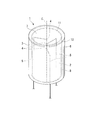
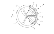
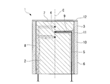
図2、図3、及び図4に示すように、熱流束センサ1は、円柱形状の本体部2と、本体部2の本体部外周面8(外面)に装着されるように形成された円筒形状のパイプ部3と、配線5を有する複数の熱センサ4と、を有している。熱センサ4は、本体部2の内部に固定されており、配線5は、熱流束センサ1の表端面7とは反対側の端部から延出している。
本体部2は、その軸方向長さが、測定対象物である飛翔体シュラウド51の厚さと略同一とされ、軸方向の第一方向の端面である表端面7は、飛翔体シュラウド51の孔部52に取り付けられた際に、飛翔体シュラウド51の表面と面一となる。即ち、熱流束センサ1は、取り付け箇所において熱流束センサ1の表端面7と飛翔体シュラウド51との間に段差がなく、フラットな状態となるように取り付けられている。
パイプ部3も同様に、その軸方向長さが、測定対象物である飛翔体シュラウド51の厚さと略同一とされており、本体部2の本体部外周面8とパイプ部3の内周面との間に所定の隙間が生じるような寸法に形成されている。また、パイプ部3の外周面は即ち熱流束センサ1の外周面6をなしている。
また、本体部2とパイプ部3は、飛翔体シュラウド51と同一の材質、例えばステンレス鋼によって形成されている。
また、本体部2とパイプ部3は、飛翔体シュラウド51と同一の材質、例えばステンレス鋼によって形成されている。
本体部2には、本体部2の本体部外周面8から本体部2の中心軸Cに向かって延び、表端面7からの距離が異なる三つの穿孔9が形成されている。穿孔9は、熱センサ4の配線5を通すのに適した孔径とされている。各々の穿孔9は本体部2の本体部外周面8より本体部2の中心軸Cまで形成されており、軸方向からみて等間隔に形成されている。具体的には、穿孔9は、その先端が本体部2の中心軸Cに配置されるように形成されている。換言すれば、各々の穿孔9の先端は、表端面7の同一法線上に配置されている。また、穿孔9の先端には後述する熱センサ4が先端に当接するように配置される。
また、熱センサ4の表端面7からの距離は、熱流束を計測するために最適な位置、例えば、表端面7近傍とされており、各々の穿孔9の軸方向位置は熱センサ4の位置に対応している。
また、熱センサ4の表端面7からの距離は、熱流束を計測するために最適な位置、例えば、表端面7近傍とされており、各々の穿孔9の軸方向位置は熱センサ4の位置に対応している。
また、本体部2の本体部外周面8には、各々の熱センサ4の配線5を埋め込むための複数の溝条10が形成されている。溝条10は、穿孔9の外周側端部より、軸方向の第一方向の反対側の第二方向(表端面7とは反対側)に延在している。
熱センサ4は、金属保護管(シース)の内部に熱電対素線を封入することによって配線5としたシース熱電対である。熱センサ4は温接点が穿孔9の先端に当接するように取り付けられている。即ち、熱センサ4の先端である温接点は、穿孔9の先端が熱流束センサ1の本体部2の中心軸に配置されていることによって、本体部2の中心軸C上に配置される。
配線5は、穿孔9及び溝条10を経由して本体部2の軸方向の第二方向の側から延出するように延ばされ、所定の測定機器に接続される。
配線5は、穿孔9及び溝条10を経由して本体部2の軸方向の第二方向の側から延出するように延ばされ、所定の測定機器に接続される。
また、穿孔9には充填材としてニッケル蝋11が充填されている。ニッケル蝋11は、可能な限り隙間が生じないように穿孔9を埋めている。即ち、穿孔9に敷設された熱センサ4の配線5は、ニッケル蝋11によって封止されている。
同様に、溝条10に配置された配線5もニッケル蝋11によって固定されている。溝条10に適用されるニッケル蝋11も可能な限り隙間が生じないように溝条10を埋めている。溝条10に盛られたニッケル蝋11は、本体部2の本体部外周面8と面一となるように加工されている。即ち、本体部2の本体部外周面8とニッケル蝋11による充填材との間に段差がなく、フラットな状態となるように形成されている。
同様に、溝条10に配置された配線5もニッケル蝋11によって固定されている。溝条10に適用されるニッケル蝋11も可能な限り隙間が生じないように溝条10を埋めている。溝条10に盛られたニッケル蝋11は、本体部2の本体部外周面8と面一となるように加工されている。即ち、本体部2の本体部外周面8とニッケル蝋11による充填材との間に段差がなく、フラットな状態となるように形成されている。
パイプ部3は、熱センサ4が配線され、ニッケル蝋11によって固定された状態の本体部2を覆うように配置されている。本体部2とパイプ部3との間の所定の隙間には、ニッケル蝋11が充填されている。
また、熱流束センサ1の表端面7及びパイプ部3の軸方向の第一方向の側の面には、酸化被膜12が形成されている。
また、熱流束センサ1の表端面7及びパイプ部3の軸方向の第一方向の側の面には、酸化被膜12が形成されている。
以上のような構成の熱流束センサ1は、飛翔体シュラウド51における所望の測定箇所に形成された孔部52に取り付けられる。その際、熱流束センサ1と孔部52との間には、ニッケル蝋11からなる充填材が充填される。
なお、上述した実施形態においては、各所に充填される充填材としてニッケルからなる蝋材を採用したが、充填材はこれに限ることはなく、空隙(隙間)による誤差を極力小さくし、かつ、充填作業に適した素材であればよい。
なお、上述した実施形態においては、各所に充填される充填材としてニッケルからなる蝋材を採用したが、充填材はこれに限ることはなく、空隙(隙間)による誤差を極力小さくし、かつ、充填作業に適した素材であればよい。
次に、本実施形態の熱流束センサ1を用いた熱流束の算出方法について説明する。
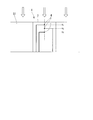
図5に示すように、本実施形態の熱流束センサ1には、三つの温度設定点が設定されており、これら三つの温度設定点には、熱センサ4の温接点が配置されている。温度設定点、即ち熱センサ4の表端面7からの距離xをそれぞれx1,x2,x3とする。
図5に示すように、本実施形態の熱流束センサ1には、三つの温度設定点が設定されており、これら三つの温度設定点には、熱センサ4の温接点が配置されている。温度設定点、即ち熱センサ4の表端面7からの距離xをそれぞれx1,x2,x3とする。
[1]まず、熱センサ4によって、各点の温度T(x1),T(x2),T(x3)が計測される。
[2]次いで、計測された温度Tを用いて、表端面7からの距離xと温度Tとの関係式を回帰分析により導出する。即ち、下記式(1)の係数a,b,cを導出する。本実施形態では温度設定点が三点であるので、関係式は二次方程式となる。
T(x)=ax2+bx+c ・・・(1)
[2]次いで、計測された温度Tを用いて、表端面7からの距離xと温度Tとの関係式を回帰分析により導出する。即ち、下記式(1)の係数a,b,cを導出する。本実施形態では温度設定点が三点であるので、関係式は二次方程式となる。
T(x)=ax2+bx+c ・・・(1)
[3]次いで、表端面x=0における熱伝導率、即ち表面熱伝導率λを、式(1)から算出する。即ち、表面温度T(0)=cから表面熱伝導率λを算出する。
[4]同様に、表端面x=0における温度勾配、即ち、表面温度勾配を式(1)から算出する。即ち、表端面x=0における表面温度勾配dT/dxは、dT/dx=bとなる。
(5)熱流束q=λ・dT/dxの関係式、及び上記[3]及び[4]より表端面x=0における熱流束qを算出する。
[4]同様に、表端面x=0における温度勾配、即ち、表面温度勾配を式(1)から算出する。即ち、表端面x=0における表面温度勾配dT/dxは、dT/dx=bとなる。
(5)熱流束q=λ・dT/dxの関係式、及び上記[3]及び[4]より表端面x=0における熱流束qを算出する。
以上に示すような工程によって算出される熱流束qは、熱流束センサ1に接続された計測機器に搭載された計算装置(コンピュータ)によって計算することができる。
次に、本実施形態の熱流束センサ1の製造方法について説明する。
まず、熱流束センサ1の基本寸法を設定する。円柱形状をなす熱流束センサ1の軸方向の長さを、測定対象部である飛翔体シュラウド51の面厚と同一をなるように設定する。次いで、熱流束センサ1の本体部2の直径、及びパイプ部3の管厚を設定する。
次いで、測定対象部である飛翔体シュラウド51に、円柱形状をなす熱流束センサ1の直径より僅かに大きい孔部52を形成する。この際、孔部52の中心軸が飛翔体シュラウド51の表面と直交するように孔部52を形成する。
まず、熱流束センサ1の基本寸法を設定する。円柱形状をなす熱流束センサ1の軸方向の長さを、測定対象部である飛翔体シュラウド51の面厚と同一をなるように設定する。次いで、熱流束センサ1の本体部2の直径、及びパイプ部3の管厚を設定する。
次いで、測定対象部である飛翔体シュラウド51に、円柱形状をなす熱流束センサ1の直径より僅かに大きい孔部52を形成する。この際、孔部52の中心軸が飛翔体シュラウド51の表面と直交するように孔部52を形成する。
次いで、本体部2に穿孔9及び溝条10を形成する。穿孔9は、本体部2の本体部外周面8から、本体部2の中心軸Cに直交する方向に、例えばドリルを用いて穿削を行うことによって形成する。本実施形態においては、三つの熱センサ4に対応して、三つの穿孔9を形成する。この際、穿孔9の周方向位置が、周方向に等間隔になるように形成する。即ち、三つの穿孔9を形成する場合は、180°間隔とする。また、穿孔9は、その先端が本体部2の中心軸Cと一致するように形成する。
溝条10は、穿孔9の外周側端部より、熱流束センサ1の本体部2の軸方向の第二方向の側に向かって、例えばフライス盤を用いて加工を行うことによって形成する。
溝条10は、穿孔9の外周側端部より、熱流束センサ1の本体部2の軸方向の第二方向の側に向かって、例えばフライス盤を用いて加工を行うことによって形成する。
次いで、穿孔9に熱センサ4を挿入する。この際、熱センサ4が穿孔9の先端に当接するまで挿入を行う。そして、熱センサ4が穿孔9の先端に当接した状態で、穿孔9をニッケル蝋11によって充填・封止する。この際、ニッケル蝋11は穿孔9の内部に空隙が生じないように充填する。
さらに、穿孔9の外周側端部より露出した配線5を溝条10の内部に沿わせ、配線5をニッケル蝋11によって固定する。この際、溝条10に盛られたニッケル蝋11が、本体部2の本体部外周面8と面一となるように追加工を行う。即ち、溝条10に盛られたニッケル蝋11とパイプ部3とが干渉しないように、ニッケル蝋11を切削する。
さらに、穿孔9の外周側端部より露出した配線5を溝条10の内部に沿わせ、配線5をニッケル蝋11によって固定する。この際、溝条10に盛られたニッケル蝋11が、本体部2の本体部外周面8と面一となるように追加工を行う。即ち、溝条10に盛られたニッケル蝋11とパイプ部3とが干渉しないように、ニッケル蝋11を切削する。
次いで、熱センサ4が取り付けられた本体部2を覆うようにパイプ部3を取り付け、本体部2とパイプ部3との間にニッケル蝋11を充填する。この際も、本体部2とパイプ部3との間に空隙が設けられないように、十分に充填を行う。
次いで、熱流束センサ1の表端面7に酸化被膜12を形成する。酸化被膜12は、パイプ部3が取り付けられた本体部2を収納容器する雰囲気温度と同様の条件にさらすことによって形成する。
最後に、熱流束センサ1を飛翔体シュラウド51の孔部52に挿入し、熱流束センサ1の外周面6と孔部52の内周面との間にニッケル蝋11を充填する。
最後に、熱流束センサ1を飛翔体シュラウド51の孔部52に挿入し、熱流束センサ1の外周面6と孔部52の内周面との間にニッケル蝋11を充填する。
上記実施形態によれば、熱センサ4を予め形成された穿孔9に配置し、熱センサ4をニッケル蝋11からなる充填材により固定する構成であるため、温度計側位置のずれによる熱流束誤差の発生を防ぐことができる。また、穿孔9の深さによって熱センサ4の位置を定めることができるため、熱センサ4の位置決めが容易となる。
また、複数の熱センサ4を固定された本体部2を、測定対象物の孔部52に取り付ける構成であるため、熱センサ4の測定対象物への配置が容易となる。
また、複数の熱センサ4を固定された本体部2を、測定対象物の孔部52に取り付ける構成であるため、熱センサ4の測定対象物への配置が容易となる。
また、測定対象物の温度が非定常状態である場合においても、三点以上の温度により熱流束を算出することによって、熱流束誤差を少なくすることができる。
また、熱流束センサ1の外周面6と孔部52の内周面との間にニッケル蝋11が充填されていることによって、本体部2と測定対象物との温度差がより小さくなるため、熱流束誤差を少なくすることができる。
また、熱流束センサ1の外周面6と孔部52の内周面との間にニッケル蝋11が充填されていることによって、本体部2と測定対象物との温度差がより小さくなるため、熱流束誤差を少なくすることができる。
また、本体部2の穿孔9が、本体部2の周方向に等間隔に設けられていることによって、本体部2の内部構造における周方向のバランスが向上するため、熱流束誤差をより少なくすることができる。
また、本体部2の本体部外周面8を覆うようにパイプ部3を設けたことによって、本体部2の本体部外周面8に形成される配線5用の溝条10などがパイプ部3によって覆われるため、本体部2の測定対象物への取り付けが容易となる。
また、本体部2の本体部外周面8を覆うようにパイプ部3を設けたことによって、本体部2の本体部外周面8に形成される配線5用の溝条10などがパイプ部3によって覆われるため、本体部2の測定対象物への取り付けが容易となる。
また、本体部2及びパイプ部3の材質を測定対象物と同一とすることによって、測定対象物と、本体部2及びパイプ部3との熱伝導による誤差影響をより小さくすることができる。
また、熱流束センサ1の表端面7に酸化被膜12が形成されていることによって、表端面7の状態が測定対象物の表面と同様の状態となるため、熱流束の誤差をより少なくすることができる。
また、熱流束センサ1の表端面7に酸化被膜12が形成されていることによって、表端面7の状態が測定対象物の表面と同様の状態となるため、熱流束の誤差をより少なくすることができる。
なお、本発明の技術範囲は、上述した各実施形態に限定されるものではなく、本発明の趣旨を逸脱しない範囲において、上述した実施形態に種々の変更を加えたものを含む。すなわち、上述した実施形態で挙げた構成等は一例であり、適宜変更が可能である。
例えば、上記実施形態においては、穿孔9を本体部2の本体部外周面8から形成する構成としたが、穿孔9は本体部2の表端面7以外から形成すればよく、本体部2の表端面7とは反対側の端面から形成する構成を採用することもできる。
また、穿孔9は、軸方向からみて周方向に等間隔に形成する例を示したが、これに限ることはなく、穿孔9の周方向の間隔を不均一、あるいは、軸方向からみて同じ位置に形成してもよい。
例えば、上記実施形態においては、穿孔9を本体部2の本体部外周面8から形成する構成としたが、穿孔9は本体部2の表端面7以外から形成すればよく、本体部2の表端面7とは反対側の端面から形成する構成を採用することもできる。
また、穿孔9は、軸方向からみて周方向に等間隔に形成する例を示したが、これに限ることはなく、穿孔9の周方向の間隔を不均一、あるいは、軸方向からみて同じ位置に形成してもよい。
また、熱センサ4の数は三つに限ることはなく、二つ、あるいは四つ以上としてもよい。四つ以上とする場合、温度計側点の温度の算出式の精度が向上するため、より好ましい。
また、上記実施形態においては、溝条10を本体に形成したが、パイプ部3の側に溝条を形成してもよい。
また、製造の容易性より、熱流束センサ1は円柱形状としたが、多角形形状などを採用することも可能である。さらに、パイプ部3を用いずに本体部2のみで熱流束センサ1を構成してもよい。
また、上記実施形態においては、溝条10を本体に形成したが、パイプ部3の側に溝条を形成してもよい。
また、製造の容易性より、熱流束センサ1は円柱形状としたが、多角形形状などを採用することも可能である。さらに、パイプ部3を用いずに本体部2のみで熱流束センサ1を構成してもよい。
本発明は、測定対象物の表面に形成された孔部に取り付けられる熱流束センサに適用可能であって、温度計側位置のずれによる熱流束誤差の発生を防ぐことができる。
1 熱流束センサ
2 本体部
3 パイプ部
4 熱センサ
5 配線
6 外周面
7 表端面
8 本体部外周面(外面)
9 穿孔
10 溝条
11 ニッケル蝋
50 飛翔体
51 飛翔体シュラウド
52 孔部
2 本体部
3 パイプ部
4 熱センサ
5 配線
6 外周面
7 表端面
8 本体部外周面(外面)
9 穿孔
10 溝条
11 ニッケル蝋
50 飛翔体
51 飛翔体シュラウド
52 孔部
Claims (9)
- 測定対象物の表面に形成された孔部に取り付けられる熱流束センサであって、
前記孔部の内周面に対向する外周面と前記測定対象物の表面と面一な表端面とを有する本体部を備え、
前記本体部に、前記本体部の表端面以外の外面から内部に向かって延びて、それぞれ先端が前記表端面の同一法線上に配置された複数の穿孔が形成され、
各前記穿孔の先端に当接するように配置され、配線が前記穿孔を経由して前記本体部の外面に至る複数の熱センサと、
前記穿孔に充填され、前記穿孔内に前記熱センサを封止する充填材と、を備えることを特徴とする熱流束センサ。 - 前記熱センサは、三つ以上設けられていることを特徴とする請求項1に記載の熱流束センサ。
- 前記本体部は円柱形状をなし、前記熱センサの前記先端は前記本体部の中心軸上に配置されていることを特徴とする請求項1又は請求項2に記載の熱流束センサ。
- 前記孔部との間に充填材が充填されていることを特徴とする請求項1から請求項3のいずれか一項に記載の熱流束センサ。
- 前記穿孔は、前記本体部の周方向に等間隔に設けられていることを特徴とする請求項1から請求項4のいずれか一項に記載の熱流束センサ。
- 前記本体部の外周面を覆うように設けられた円筒状のパイプ部を備え、
前記本体部と前記パイプ部との間には、充填材が充填されていることを特徴とする請求項1から請求項5のいずれか一項に記載の熱流束センサ。 - 前記本体部及び前記パイプ部の材質は、前記測定対象物と同一とされていることを特徴とする請求項6に記載の熱流束センサ。
- 前記表端面に酸化被膜が形成されていることを特徴とする請求項1から請求項7のいずれか一項に記載の熱流束センサ。
- 測定対象物の表面に孔部を形成する工程と、
前記孔部の内周面に対向する外周面と前記測定対象物の表面と面一な表端面とを有する本体部を形成する工程と、
前記本体部に、前記本体部の表端面以外の外面から内部に向かって延びて、それぞれ先端が前記表端面の同一法線上に配置される複数の穿孔を形成する工程と、
複数の熱センサを各前記穿孔の先端に当接するように配置し、配線を前記穿孔を経由して前記本体部の外面に至るように配線する工程と、
前記穿孔内に前記熱センサを封止するように充填材を充填する工程と、
を含むことを特徴とする熱流束センサの製造方法。
Priority Applications (1)
| Application Number | Priority Date | Filing Date | Title |
|---|---|---|---|
| US14/443,162 US9909936B2 (en) | 2012-12-27 | 2013-12-25 | Heat flux sensor and method for manufacturing same |
Applications Claiming Priority (2)
| Application Number | Priority Date | Filing Date | Title |
|---|---|---|---|
| JP2012285917A JP5931715B2 (ja) | 2012-12-27 | 2012-12-27 | 熱流束センサ及び熱流束センサの製造方法 |
| JP2012-285917 | 2012-12-27 |
Publications (1)
| Publication Number | Publication Date |
|---|---|
| WO2014104077A1 true WO2014104077A1 (ja) | 2014-07-03 |
Family
ID=51021155
Family Applications (1)
| Application Number | Title | Priority Date | Filing Date |
|---|---|---|---|
| PCT/JP2013/084624 Ceased WO2014104077A1 (ja) | 2012-12-27 | 2013-12-25 | 熱流束センサ及び熱流束センサの製造方法 |
Country Status (3)
| Country | Link |
|---|---|
| US (1) | US9909936B2 (ja) |
| JP (1) | JP5931715B2 (ja) |
| WO (1) | WO2014104077A1 (ja) |
Cited By (2)
| Publication number | Priority date | Publication date | Assignee | Title |
|---|---|---|---|---|
| CN110082005A (zh) * | 2019-05-23 | 2019-08-02 | 江西联创光电科技股份有限公司 | 一种导体棒料内部温度的非均匀采样测量方法和设备 |
| CN110082006A (zh) * | 2019-05-23 | 2019-08-02 | 江西联创光电科技股份有限公司 | 一种导体棒料内部温度的均匀采样测量方法和设备 |
Families Citing this family (3)
| Publication number | Priority date | Publication date | Assignee | Title |
|---|---|---|---|---|
| US10976204B2 (en) * | 2018-03-07 | 2021-04-13 | Rosemount Inc. | Heat flux sensor with improved heat transfer |
| DE102019206013A1 (de) * | 2019-04-26 | 2020-10-29 | Fraunhofer-Gesellschaft zur Förderung der angewandten Forschung e.V. | Grenzschichtsensor, dessen Herstellung und Verwendung |
| FR3132765B1 (fr) * | 2022-02-17 | 2024-04-26 | Office National Detudes Rech Aerospatiales | Capteurs pour systèmes de mesure de flux thermique à inertie |
Citations (6)
| Publication number | Priority date | Publication date | Assignee | Title |
|---|---|---|---|---|
| JPS4974274U (ja) * | 1972-10-11 | 1974-06-27 | ||
| JPS63105853U (ja) * | 1986-12-27 | 1988-07-08 | ||
| JPH02133640U (ja) * | 1989-04-13 | 1990-11-06 | ||
| JPH05164626A (ja) * | 1991-12-11 | 1993-06-29 | Kawasaki Steel Corp | 熱電対を用いた温度測定方法 |
| JPH07146189A (ja) * | 1993-11-24 | 1995-06-06 | Mitsubishi Heavy Ind Ltd | 表面熱流束計測装置 |
| JP2003130737A (ja) * | 2001-10-29 | 2003-05-08 | Sukegawa Electric Co Ltd | 熱流束計 |
Family Cites Families (19)
| Publication number | Priority date | Publication date | Assignee | Title |
|---|---|---|---|---|
| US3267726A (en) * | 1961-09-14 | 1966-08-23 | North American Aviation Inc | Heat flux probe |
| JPS537463B2 (ja) | 1972-11-17 | 1978-03-17 | ||
| US3996070A (en) * | 1974-11-22 | 1976-12-07 | Nasa | Thermocouple installation |
| JPH0639033B2 (ja) | 1986-10-23 | 1994-05-25 | 東芝機械株式会社 | 自動工具交換装置 |
| US4778538A (en) * | 1987-07-15 | 1988-10-18 | Westinghouse Electric Corp. | Dual temperature sensing device having twin well thermowell for dual resistance temperature detectors |
| US4916715A (en) * | 1988-04-13 | 1990-04-10 | General Electric Company | Method and apparatus for measuring the distribution of heat flux and heat transfer coefficients on the surface of a cooled component used in a high temperature environment |
| US4904091A (en) * | 1988-09-15 | 1990-02-27 | The United States Of America As Represented By The Administrator Of The National Aeronautics And Space Administration | Threaded average temperature thermocouple |
| JPH02133640A (ja) | 1988-11-11 | 1990-05-22 | Nippon Felt Kogyo Kk | 不織布 |
| US5048973A (en) * | 1990-05-31 | 1991-09-17 | United States Of America, As Represented By The Administrator Of The National Aeronautics And Space Administration | Plug-type heat flux gauge |
| US5086204A (en) * | 1990-05-31 | 1992-02-04 | The United States Of America As Represented By The Administrator Of The National Aeronautics And Space Administration | Method of producing a plug-type heat flux gauge |
| FR2716534B1 (fr) * | 1994-02-22 | 1996-05-24 | Univ Nantes | Procédé et dispositif de mesure en régime transitoire de températures et flux surfaciques. |
| US5697706A (en) * | 1995-12-26 | 1997-12-16 | Chrysler Corporation | Multi-point temperature probe |
| US5999081A (en) * | 1996-11-29 | 1999-12-07 | Marchi Associates, Inc. | Shielding unique for filtering RFI and EFI interference signals from the measuring elements |
| JPH10274629A (ja) | 1997-01-29 | 1998-10-13 | Mitsubishi Heavy Ind Ltd | 熱伝達率の計測装置 |
| US6485174B1 (en) * | 2000-10-27 | 2002-11-26 | The Babcock & Wilcox Company | Attachable heat flux measuring device |
| US6550963B2 (en) * | 2001-04-26 | 2003-04-22 | Daily Instruments | Multipoint thermocouple |
| US20040136434A1 (en) * | 2003-01-13 | 2004-07-15 | Langley Lawrence W. | Laminated heat flux indicating device |
| JP4813949B2 (ja) | 2006-03-31 | 2011-11-09 | 株式会社日立国際電気 | 熱電対の固定具および被測温物の温度制御装置 |
| US8147130B2 (en) * | 2008-04-18 | 2012-04-03 | General Electric Company | Heat flux measurement device for estimating fouling thickness |
-
2012
- 2012-12-27 JP JP2012285917A patent/JP5931715B2/ja active Active
-
2013
- 2013-12-25 WO PCT/JP2013/084624 patent/WO2014104077A1/ja not_active Ceased
- 2013-12-25 US US14/443,162 patent/US9909936B2/en active Active
Patent Citations (6)
| Publication number | Priority date | Publication date | Assignee | Title |
|---|---|---|---|---|
| JPS4974274U (ja) * | 1972-10-11 | 1974-06-27 | ||
| JPS63105853U (ja) * | 1986-12-27 | 1988-07-08 | ||
| JPH02133640U (ja) * | 1989-04-13 | 1990-11-06 | ||
| JPH05164626A (ja) * | 1991-12-11 | 1993-06-29 | Kawasaki Steel Corp | 熱電対を用いた温度測定方法 |
| JPH07146189A (ja) * | 1993-11-24 | 1995-06-06 | Mitsubishi Heavy Ind Ltd | 表面熱流束計測装置 |
| JP2003130737A (ja) * | 2001-10-29 | 2003-05-08 | Sukegawa Electric Co Ltd | 熱流束計 |
Cited By (2)
| Publication number | Priority date | Publication date | Assignee | Title |
|---|---|---|---|---|
| CN110082005A (zh) * | 2019-05-23 | 2019-08-02 | 江西联创光电科技股份有限公司 | 一种导体棒料内部温度的非均匀采样测量方法和设备 |
| CN110082006A (zh) * | 2019-05-23 | 2019-08-02 | 江西联创光电科技股份有限公司 | 一种导体棒料内部温度的均匀采样测量方法和设备 |
Also Published As
| Publication number | Publication date |
|---|---|
| JP2014126545A (ja) | 2014-07-07 |
| US9909936B2 (en) | 2018-03-06 |
| US20150292961A1 (en) | 2015-10-15 |
| JP5931715B2 (ja) | 2016-06-08 |
Similar Documents
| Publication | Publication Date | Title |
|---|---|---|
| JP5931715B2 (ja) | 熱流束センサ及び熱流束センサの製造方法 | |
| US9243963B2 (en) | Total temperature probe | |
| JP4751492B2 (ja) | 熱電対 | |
| WO2008140512A3 (en) | Exhaust gas temperature sensor with fast response | |
| TWI641782B (zh) | 鍋爐 | |
| ITUB20150948A1 (it) | Elemento di fissaggio, uso di un sensore integrato nell'elemento di fissaggio e metodo per rilevare un flusso termico all'interno di organi meccanici | |
| CN103353355A (zh) | 一种用于高温环境下的温度、热流测量的传感器 | |
| CN106840268B (zh) | 一种集成总温测量的五孔探针 | |
| Singh et al. | Error in temperature measurements due to conduction along the sensor leads | |
| US12092502B2 (en) | Non-invasive thermometer | |
| JP2014126545A5 (ja) | ||
| JP5366772B2 (ja) | 温度検出装置 | |
| JP2012207932A (ja) | 温度分布測定センサ | |
| KR101831682B1 (ko) | 기체 온도 측정 장치 및 방법 | |
| Brewer | Effect of thermocouple wire size and configuration on internal temperature measurements in a charring Ablator | |
| JP7331726B2 (ja) | 工具摩耗量予測方法及び工具摩耗量予測システム | |
| CN105157873B (zh) | 圆环式光纤光栅温度传感器及封装方法 | |
| JP6804439B2 (ja) | 迅速応答センサ筐体 | |
| JP3782958B2 (ja) | 熱流束計 | |
| CN206876305U (zh) | 一种可实现不同插深的热电偶 | |
| CN205484146U (zh) | 用于测量物品热物性的测量装置 | |
| JPS6145463Y2 (ja) | ||
| JPH088429Y2 (ja) | 温度分布検知センサ | |
| JP2006234734A (ja) | 温度センサ配置部材およびこれを備えた温度計 | |
| JP2015075460A (ja) | 状態量の検出装置及び検出方法 |
Legal Events
| Date | Code | Title | Description |
|---|---|---|---|
| 121 | Ep: the epo has been informed by wipo that ep was designated in this application |
Ref document number: 13866896 Country of ref document: EP Kind code of ref document: A1 |
|
| WWE | Wipo information: entry into national phase |
Ref document number: 14443162 Country of ref document: US |
|
| NENP | Non-entry into the national phase |
Ref country code: DE |
|
| 122 | Ep: pct application non-entry in european phase |
Ref document number: 13866896 Country of ref document: EP Kind code of ref document: A1 |