WO2014103810A1 - 野菜果汁製造装置、野菜果汁製造方法及び野菜果汁 - Google Patents
野菜果汁製造装置、野菜果汁製造方法及び野菜果汁 Download PDFInfo
- Publication number
- WO2014103810A1 WO2014103810A1 PCT/JP2013/083800 JP2013083800W WO2014103810A1 WO 2014103810 A1 WO2014103810 A1 WO 2014103810A1 JP 2013083800 W JP2013083800 W JP 2013083800W WO 2014103810 A1 WO2014103810 A1 WO 2014103810A1
- Authority
- WO
- WIPO (PCT)
- Prior art keywords
- helical
- gears
- teeth
- gear
- spur
- Prior art date
- Legal status (The legal status is an assumption and is not a legal conclusion. Google has not performed a legal analysis and makes no representation as to the accuracy of the status listed.)
- Ceased
Links
Images


Classifications
-
- A—HUMAN NECESSITIES
- A23—FOODS OR FOODSTUFFS; TREATMENT THEREOF, NOT COVERED BY OTHER CLASSES
- A23L—FOODS, FOODSTUFFS OR NON-ALCOHOLIC BEVERAGES, NOT OTHERWISE PROVIDED FOR; PREPARATION OR TREATMENT THEREOF
- A23L2/00—Non-alcoholic beverages; Dry compositions or concentrates therefor; Preparation or treatment thereof
- A23L2/02—Non-alcoholic beverages; Dry compositions or concentrates therefor; Preparation or treatment thereof containing fruit or vegetable juices
- A23L2/04—Extraction of juices
-
- A—HUMAN NECESSITIES
- A23—FOODS OR FOODSTUFFS; TREATMENT THEREOF, NOT COVERED BY OTHER CLASSES
- A23N—MACHINES OR APPARATUS FOR TREATING HARVESTED FRUIT, VEGETABLES OR FLOWER BULBS IN BULK, NOT OTHERWISE PROVIDED FOR; PEELING VEGETABLES OR FRUIT IN BULK; APPARATUS FOR PREPARING ANIMAL FEEDING- STUFFS
- A23N1/00—Machines or apparatus for extracting juice
- A23N1/02—Machines or apparatus for extracting juice combined with disintegrating or cutting
-
- A—HUMAN NECESSITIES
- A47—FURNITURE; DOMESTIC ARTICLES OR APPLIANCES; COFFEE MILLS; SPICE MILLS; SUCTION CLEANERS IN GENERAL
- A47J—KITCHEN EQUIPMENT; COFFEE MILLS; SPICE MILLS; APPARATUS FOR MAKING BEVERAGES
- A47J19/00—Household machines for straining foodstuffs; Household implements for mashing or straining foodstuffs
- A47J19/02—Citrus fruit squeezers; Other fruit juice extracting devices
- A47J19/025—Citrus fruit squeezers; Other fruit juice extracting devices including a pressing screw
-
- A—HUMAN NECESSITIES
- A47—FURNITURE; DOMESTIC ARTICLES OR APPLIANCES; COFFEE MILLS; SPICE MILLS; SUCTION CLEANERS IN GENERAL
- A47J—KITCHEN EQUIPMENT; COFFEE MILLS; SPICE MILLS; APPARATUS FOR MAKING BEVERAGES
- A47J19/00—Household machines for straining foodstuffs; Household implements for mashing or straining foodstuffs
- A47J19/06—Juice presses for vegetables
-
- Y—GENERAL TAGGING OF NEW TECHNOLOGICAL DEVELOPMENTS; GENERAL TAGGING OF CROSS-SECTIONAL TECHNOLOGIES SPANNING OVER SEVERAL SECTIONS OF THE IPC; TECHNICAL SUBJECTS COVERED BY FORMER USPC CROSS-REFERENCE ART COLLECTIONS [XRACs] AND DIGESTS
- Y10—TECHNICAL SUBJECTS COVERED BY FORMER USPC
- Y10S—TECHNICAL SUBJECTS COVERED BY FORMER USPC CROSS-REFERENCE ART COLLECTIONS [XRACs] AND DIGESTS
- Y10S241/00—Solid material comminution or disintegration
- Y10S241/27—Pill or tablet crushers
Definitions
- the present invention relates to a vegetable juice production apparatus, a vegetable juice production method, and a vegetable fruit juice.
- the squeezing machine described in Patent Documents 1 and 2 is composed of a pulverizing portion made of helical gears and a squeezing roller made of Archimedes screw or the like that squeezes while transferring the crushed soup material.
- This invention is made
- the object is to provide a large amount of nutritious vegetable juice.
- a vegetable fruit juice production device comprises: A first crushing portion comprising a set of spur gears, passing a soup material between the set of spur gears and crushing the soup material with teeth of the spur gear; A set of first helical gears having a greater number of teeth than the number of teeth of the spur gear, and in the vertically downward direction of the intermediate position of the rotation shaft of the set of spur gears, A second crushing portion that has an intermediate position of a rotation shaft and crushes the juice material crushed by the first crushing portion by teeth of the first helical gear; It is characterized by providing.
- the distance between the rotation shafts of the pair of spur gears of the first crushing part may be changeable.
- the teeth of the spur gear and the first helical gear may not have an acute angle.
- the pair of spur gears may be driven to rotate in the opposite directions to each other with substantially the same power.
- the rotational speed of the spur gear may be equal to or slower than the rotational speed of the first helical gear.
- a third crushing part that crushes the juice material that has been crushed by the second crushing part with the teeth of the second helical gear.
- the teeth of the second helical gear may not have an acute angle.
- the rotation speed of the first helical gear may be equal to or slower than the rotation speed of the second helical gear.
- the soup material vegetable or fruit may be poured substantially vertically downward between the two spur gears of the first crushing portion.
- the vegetable juice manufacturing method which concerns on the 2nd viewpoint of this invention is the following.
- the vegetable juice which concerns on the 3rd viewpoint of this invention is The juice material is passed between at least one set of spur gears and / or at least one set of helical gears to crush the juice material, and the residual ratio of vitamin C is relative to the original juice material. It is characterized by being 90% or more.
- the vegetable juice which concerns on the 4th viewpoint of this invention is A first crushing step of passing the soup material between a set of spur gears and crushing the soup material with teeth of the spur gear; Between a pair of first helical gears having a number of teeth greater than the number of teeth of the spur gear, provided that the meshing position comes to a position where the juice material crushed in the first crushing step falls.
- a second crushing step of passing the soup material crushed in the first crushing step and crushing the soup material with teeth of the first helical gear It is produced by the manufacturing method which has this.
- the juice can be collected while containing a large amount of vitamin C and keeping the nutritional value high regardless of the size and shape of the juice material.
- FIG. (A) It is a side view of a spur gear. (B) It is a side view of the 1st helical gear. (A) It is a top view of a spur gear. (B) It is a top view of the 1st helical gear. (A) It is sectional drawing of a spur gear. (B) It is sectional drawing of a 1st helical gear. It is a figure for demonstrating the mechanism which moves the center axis
- FIG. 1 It is a figure for demonstrating the rotational drive method of a spur gear.
- B It is a figure for demonstrating the rotational drive method of a 1st helical gear. It is a figure for demonstrating the flow of the soup material in the vegetable juice manufacturing apparatus which concerns on Embodiment 1.
- FIG. It is a figure which shows the structure of the vegetable juice manufacturing apparatus which concerns on Embodiment 2.
- FIG. (A) It is a top view of the 1st helical gear.
- B It is a top view of the 2nd helical gear.
- A It is sectional drawing of a spur gear.
- B It is sectional drawing of a 1st helical gear.
- C It is sectional drawing of a 2nd helical gear.
- FIG. 1 It is a figure for demonstrating the flow of the soup material in the vegetable juice manufacturing apparatus which concerns on Embodiment 2.
- FIG. It is a figure which shows the evaluation result of vitamin C content of the vegetable juice manufactured with the vegetable juice manufacturing apparatus which concerns on Embodiment 2.
- FIG. 1 shows the evaluation result of vitamin C content of the vegetable juice manufactured with the vegetable juice manufacturing apparatus which concerns on Embodiment 2.
- the vegetable juice production apparatus 1 includes flat gears 11 and 12, first helical gears 13 and 14, and a casing (broken line) 15 surrounding them.
- the spur gears 11 and 12 and the first helical gears 13 and 14 have through holes extending in the rotation axis direction, and the center shafts 111, 121, 131, and 141 are inserted into the through holes, respectively.
- the central shafts 111, 121, 131, 141 are fixed to the housing 15.
- the flat gears 11 and 12 and the first helical gears 13 and 14 have substantially the same diameter and the length in the rotation axis direction.
- the diameter and the length in the direction of the rotation axis may be arbitrary, but for example, the diameter is 250 mm and the length in the direction of the rotation axis is 1000 mm.
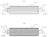
- the spur gears 11 and 12 are gears in which teeth are provided in parallel to the rotation shafts 1111 and 1211 as shown in the side view of FIG.
- the first helical gears 13 and 14 are gears formed in a spiral shape with teeth inclined with respect to the rotation shafts 1311 and 1411.
- the rotation shafts 1111, 1211, 1311, and 1411 are shafts that are fixed in position when the spur gears 11 and 12 and the first helical gears 13 and 14 are rotated.
- Each rotation axis is an axis that passes through the center of the cross section of each gear in a plane perpendicular to the extending direction of the spur gears 11 and 12 and the first helical gears 13 and 14.
- the spur gear 11 and the spur gear 12 are engaged with each other, or the distance between the tip of the tooth and the bottom of the trough of the tooth is about 3 mm. It is installed as follows. Further, as shown in the top view of FIG. 3B, the first helical gear 13 and the first helical gear 14 are installed so that the spiral directions are opposite to each other and mesh with each other.
- the rotation shaft 1311 of the first helical gear 13 and the rotation shaft of the first helical gear 14 are vertically downward at an intermediate position between the rotation shaft 1111 of the flat gear 11 and the rotation shaft 1211 of the flat gear 12. 1411 and an intermediate position. Further, the rotation shafts 1111, 1211, 1311, and 1411 of the spur gear 11, the spur gear 12, the first helical gear 13, and the first helical gear 14 are parallel to each other. Such an arrangement is for the juice material that has passed between the spur gear 11 and the spur gear 12 to fall between the first helical gear 13 and the first helical gear 14.
- the housing 15 is formed so as to surround the spur gears 11 and 12 and the first helical gears 13 and 14, and all or part of the uppermost surface 151 and the lowermost surface 152 are opened.
- FIG. 4A is a cross-sectional view in a plane perpendicular to the rotation axes 1111 and 1211 of the spur gears 11 and 12, and FIG. 4B is a view perpendicular to the rotation axes 1311 and 1411 of the first helical gears 13 and 14. It is sectional drawing in a plane. Note that adjustment is made so that a gap is not generated as much as possible between the first helical gear 13 and the first helical gear 14.
- the number of teeth of the spur gears 11 and 12 is smaller than the number of teeth of the first helical gears 13 and 14.
- the number of teeth of the spur gears 11 and 12 is 15, and the number of teeth of the first helical gears 13 and 14 is 24.
- the outer frames of the spur gears 11 and 12 and the first helical gears 13 and 14 have a straight line 1001 perpendicular to the diametrical direction of each gear and both ends thereof. It has two obtuse angles 1002 and there is no acute angle part on the surface of each gear tooth. If teeth having acute angles are used, cells of nutrients such as vitamin C of the juice material may be destroyed. Therefore, the shape of the teeth is such that the juice material is crushed.
- FIG. 5A is a front view of the spur gears 11 and 12 as seen from the front in the rotation axis direction.
- FIG. 5B is a part of a side view of the spur gear 12 viewed from the direction A in FIG.
- the distal end portion of the central shaft 121 is threaded, and the distal end of the central shaft 121 is passed through one nut 126 and then passed through the horizontally long through hole 125 of the shaft moving mechanism 20. Fastened with two nuts 126 from both sides of the shaft moving mechanism 20 and fixed.
- the central shaft 111 is also fixed to the shaft moving mechanism 20.
- the distance between the flat gear 11 and the flat gear 12 varies depending on the type of soup material.
- the distance between the flat gear 11 and the flat gear 12 is shortened.
- the teeth of the spur gear 11 and the spur gear 12 are engaged with each other by about 10 mm.
- the distance between the flat gear 11 and the flat gear 12 is increased.
- the distance (gap) between the tips of the teeth of the spur gear 11 and the spur gear 12 and the bottom of the valley of the teeth is set to about 3 mm.
- Motors 22 and 23 are provided outside the housing 15. The power of the motor 22 is transmitted to the spur gears 11 and 12 by the belt 221, and the power of the motor 23 is transmitted to the first helical gears 13 and 14 by the belt 231, whereby each gear rotates.
- a belt 221 is wound around a part of the outer periphery of the power transmission unit 122 of the spur gear 12, and the spur gear 12 rotates counterclockwise by the counterclockwise rotation of the motor 22.
- a belt 222 is wound around a part of the outer periphery of the power transmission unit 122 of the spur gear 12 and the power transmission unit 112 of the spur gear 11. The belt 222 crosses between the spur gear 11 and the spur gear 12.
- the power of counterclockwise rotation of the flat gear 12 is transmitted to the flat gear 11 by the belt 222, and the flat gear 11 rotates clockwise. That is, substantially the same power is transmitted to the spur gear 11 and the spur gear 12, and they rotate in the opposite directions and at substantially the same speed.
- a belt 231 is wound around a part of the outer periphery of the power transmission unit 142 of the first helical gear 14, and the first helical gear 14 rotates counterclockwise by the counterclockwise rotation of the motor 23. Since the first helical gear 14 and the first helical gear 13 are engaged with each other as shown in FIG. 6B, the counterclockwise rotation power of the first helical gear 14 is increased by the engagement of the teeth. 1 is transmitted to the helical gear 13. With this power, the first helical gear 13 rotates clockwise. That is, the first helical gear 13 and the first helical gear 14 rotate in the opposite directions and at substantially the same speed.
- the rotation speed of the spur gears 11 and 12 is equal to or slower than the rotation speed of the first helical gears 13 and 14.
- the rotational speed of the spur gears 11 and 12 is 60 rpm
- the rotational speed of the first helical gears 13 and 14 is 70 rpm.
- FIG. 7 is a side view seen from the front right side of FIG.
- the soup material is poured vertically downward from the opening of the uppermost surface 151 at the top of the housing 15 (arrow A).
- the introduced soup material enters between the spur gears 11 and 12 and falls in a state of being crushed by the teeth of the spur gears 11 and 12 rotating in the opposite directions (arrow B).
- the juice material falling from between the spur gears 11 and 12 enters between the first helical gears 13 and 14 and is further crushed by the teeth rotating in the opposite directions of the first helical gears 13 and 14.
- the crushed soup material moves between the first helical gears 13 and 14 along the tooth grooves of the first helical gears 13 and 14 (arrow C). Then, it falls in the state by which it was crushed to the space
- the juice material dropped from between the first helical gears 13 and 14 is transferred to a squeezing device that performs the next squeezing process.
- a squeezing device that performs the next squeezing process.
- pressure is applied in a state where the juice material is wrapped in a cloth or the like, and the vegetable juice is taken out.
- the residue after taking out the vegetable juice can be used in other forms because it has a lot of fiber and high nutritional value.
- the residue may be dried and processed into a supplement form.
- the vegetable juice production apparatus 1 is composed of a pair of flat gears 11 and 12 and first helical gears 13 and 14 positioned below the pair of flat gears 11 and 12. , 14 has more teeth than the spur gears 11, 12.
- the soup material passes between the flat gear 11 and the flat gear 12 that rotate in the opposite directions and between the first helical gear 13 and the first helical gear 14 that rotate in the opposite directions while being crushed.
- the vegetable juice production apparatus 1 can be crushed irrespective of the size and shape of the juice material, and can recover the vegetable juice while keeping the nutritional value high without destroying the nutrient cells.
- the soup material is only crushed by the spur gears 11 and 12 and the first helical gears 13 and 14, the surface area of the soup material that comes into contact with air is smaller than a juicer or the like whose blade rotates at high speed. For this reason, the oxidation of the soup material can be suppressed. Since this apparatus is configured to squeeze the juice only by crushing rather than finely cutting the material, the cells are not destroyed, and in particular, the residual rate of vitamin C is dramatically improved.
- the vegetable juice production apparatus 3 includes spur gears 11 and 12, first helical gears 13 and 14, second helical gears 17 and 18, and a casing surrounding them. (Dotted line) 35 is provided.
- the configurations of the spur gears 11 and 12 and the first helical gears 13 and 14 are the same as those in the first embodiment.
- the second helical gears 17 and 18 Similar to the first helical gears 13 and 14, the second helical gears 17 and 18 have through holes extending in the rotation axis direction, and central shafts 171 and 181 are inserted into the through holes.
- the central shafts 171 and 181 are fixed to the housing 35 together with the central shafts 111 and 121 of the spur gears 11 and 12 and the central shafts 131 and 141 of the first helical gears 13 and 14.
- the second helical gears 17 and 18 have substantially the same diameter and the length in the rotation axis direction as the flat gears 11 and 12 and the first helical gears 13 and 14.
- the second helical gears 17 and 18 are gears formed in a spiral shape with teeth inclined with respect to the rotation shafts 1711 and 1811.
- a power transmission unit 182 for rotating the gear is provided at one end of the second helical gear 18. The power from the motor or the like is transmitted to the gear power transmission unit 182 using a belt or the like.
- the second helical gear 17 and the second helical gear 18 are installed in mesh with each other with the spiral directions being opposite to each other.
- 9A and 9B the spiral directions of the second helical gear 17 and the first helical gear 13 are opposite to each other, and the second helical gear 18 and the first helical gear are in reverse directions.
- the directions of the 14 spirals are opposite to each other.
- the rotation shaft 1311 of the first helical gear 13 and the rotation shaft 1411 of the first helical gear 14 are vertically downward at the intermediate position between the rotation shaft 1111 of the flat gear 11 and the rotation shaft 1211 of the flat gear 12. There is an intermediate position. And between the rotary shaft 1711 of the second helical gear 18 and the rotary shaft 1811 of the second helical gear 18 in the vertically downward direction between the rotary shaft 1311 of the first helical gear 13 and the rotary shaft 1411 of the first helical gear 14. There is a position.
- the rotation shafts 1111, 1211, 1311, 1411, 1711, 1811 of the spur gear 11, the spur gear 12, the first helical gear 13, the first helical gear 14, the second helical gear 17, and the second helical gear 18 are mutually connected. Parallel.
- the soup material that has passed between the spur gear 11 and the spur gear 12 falls between the first helical gear 13 and the first helical gear 14, and further, the first helical gear 13 and the first helical gear.
- the soup material that has passed between the gears 14 is to fall between the second helical gear 17 and the second helical gear 18.
- the housing 35 is formed so as to surround the entire spur gears 11 and 12, the first helical gears 13 and 14, and the second helical gears 17 and 18, and all or part of the uppermost surface 351 and the lowermost surface 352 are formed. It is open.
- FIG. 10A is a cross-sectional view in a plane perpendicular to the rotation axes 1111 and 1211 of the flat gears 11 and 12, and FIG. 10B is a plane perpendicular to the rotation axes 1311 and 1411 of the first helical gears 13 and 14.
- FIG. 10C is a cross-sectional view in a plane perpendicular to the rotating shafts 1711 and 1811 of the second helical gears 17 and 18.
- the number of teeth of the spur gears 11 and 12 is smaller than the number of teeth of the first helical gears 13 and 14, and the number of teeth of the first helical gears 13 and 14 is smaller than the number of teeth of the second helical gears 17 and 18. .
- the number of teeth of the spur gears 11 and 12 is 15, the number of teeth of the first helical gears 13 and 14 is 24, and the number of teeth of the second helical gears 17 and 18 is 32.
- the cross-sectional shape of the teeth of the second helical gears 17 and 18 is the same as the cross-sectional shape of the teeth of the spur gears 11 and 12 and the first helical gears 13 and 14, and the outer frame of the tooth cross-section is a straight line perpendicular to the diametrical direction. And two obtuse angles at both ends thereof, and there is no acute angle portion on the surface of each gear tooth.
- the method for rotationally driving the spur gears 11 and 12 and the first helical gears 13 and 14 is the same as in the first embodiment.
- the method of rotational driving of the second helical gears 17 and 18 is the same as that of the first helical gears 13 and 14.
- the power from the motor is transmitted to the second helical gear 18 through a belt wound around a part of the outer periphery of the power transmission portion 182 of the second helical gear 18. With this power, the second helical gear 18 rotates counterclockwise. As shown in FIG. 9B, the second helical gear 17 and the second helical gear 18 are engaged with each other, so that the counterclockwise rotation power of the second helical gear 18 is increased by the engagement of the teeth. 2 is transmitted to the helical gear 17. With this power, the second helical gear 17 rotates clockwise. That is, the second helical gear 17 and the second helical gear 18 rotate in the opposite directions and at substantially the same speed.
- the rotational speed of the spur gears 11 and 12 is equal to or slower than the rotational speed of the first helical gears 13 and 14, and the rotational speed of the first helical gears 13 and 14 is the same as the rotational speed of the second helical gears 17 and 18. Compared or slow compared.
- the rotation speed of the spur gears 11 and 12 is 60 rpm
- the rotation speed of the first helical gears 13 and 14 is 70 rpm
- the rotation speed of the second helical gears 17 and 18 is also 70 rpm.
- the rotation speed of each gear can be adjusted in view of the stagnation status of the soup material, the crushing status, and the cell destruction status.
- the soup material that has passed through the spur gears 11 and 12 stays in the first helical gears 13 and 14, and the soup material that has passed through the first helical gears 13 and 14 becomes in the second helical gears 17 and 18. It is possible to prevent the stagnation and smoothly extract the crushed juice material. That is, the crushing capacity of the second helical gears 17 and 18 is larger than the capacity of the soup material sent from the first helical gears 13 and 14, and this relationship is related to the first helical gears 13 and 14 and the spur gear 11. , 12 is the same. This relationship prevents the soup material from stagnation.
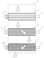
- FIG. 11 is a side view seen from the front right side of FIG.
- the soup material is fed from the opening of the uppermost surface 351 at the top of the housing 35 (arrow A).
- the introduced soup material enters between the spur gears 11 and 12 and falls in a state of being crushed by the teeth of the spur gears 11 and 12 rotating in the opposite directions (arrow B).
- the soup material falling from between the spur gears 11 and 12 enters between the first helical gears 13 and 14 and is further crushed by teeth rotating in the opposite directions of the first helical gears 13 and 14.
- the crushed soup material advances between the first helical gears 13 and 14 along the teeth of the first helical gears 13 and 14 (arrow C).
- the first helical gears 13 and 14 are dropped in a state where they are torn to the interval of the teeth (arrow D).
- the crushed soup material advances between the second helical gears 17 and 18 along the teeth of the second helical gears 17 and 18 (arrow E).
- the soup material proceeds in the opposite direction (arrows C and E). After that, it is finely cut to the interval of the teeth of the second helical gears 17 and 18 and dropped as a paste (arrow F).
- the juice material dropped from between the second helical gears 17 and 18 is transferred to a squeezing device that performs the next squeezing process.
- a squeezing device that performs the next squeezing process.
- pressure is applied in a state where the juice material is wrapped in a cloth or the like, and the vegetable juice is taken out.
- the vegetable juice production apparatus 3 includes a pair of flat gears 11 and 12, a pair of first helical gears 13 and 14 positioned below the pair, and a position below the pair of first helical gears 13 and 14. And a pair of second helical gears 17 and 18.
- the number of teeth of the second helical gears 17 and 18 is larger than the number of teeth of the first helical gears 13 and 14.
- the soup material is between the flat gear 11 and the flat gear 12 that rotate in the opposite directions, between the first helical gear 13 and the first helical gear 14 that rotate in the opposite directions, and the second helical that rotates in the opposite direction. It passes between the gear 17 and the second helical gear 18 while being crushed in order. Thereby, the vegetable juice production apparatus 3 can be crushed irrespective of the size and shape of the juice material, and can process the juice material to a more finely crushed state without destroying the nutrient cells. Vegetable juice can be recovered while keeping it high.
- Vegetable juice was manufactured using the kale as a soup material with the vegetable juice manufacturing apparatus 3 which concerns on Embodiment 2.
- FIG. about this vegetable juice content of total vitamin C was measured by the high performance liquid chromatograph method. The result is shown in FIG. In FIG. 12, the measurement result of the total vitamin C content by the high performance liquid chromatographic method is shown also about the vegetable leaf manufactured with the basic leaf of kale and the general electric juicer for the comparison.
- the total vitamin C content per 100 g of the vegetable juice produced by the vegetable juice production apparatus 3 according to Embodiment 2 is 118 mg, which is about the same as 123 g of kale base leaves. Only 4% decrease. It can be seen that the total vitamin C cells remain intact without being destroyed even when compared with 21 mg produced by an electric juicer.
- the vegetable fruit juice producing apparatus includes the first crushing portion made of a set of spur gears and the second set of first helical gears having a number of teeth larger than the number of teeth of the spur gear. Crushing part. There is an intermediate position of the rotary shaft of the first helical gear in the vertically downward direction of the intermediate position of the rotary shaft of the pair of flat gears, and the juice material crushed by the teeth of the flat gear of the first crushing portion is the first position. Further crushing is performed by the helical gear teeth of the second crushing portion. Thereby, regardless of the size and shape of the soup material, the soup can be collected while containing a large amount of vitamin C and keeping the nutritional value high.
- the first helical gears 13 and 14 and the second helical gears 17 and 18 are driven by the power transmission unit 142 of the first helical gear 14 and the power transmission unit 182 of the second helical gear 18.
- the power of the motor 23 and the like was transmitted to the motor.
- a power transmission unit may be provided in the first helical gear 13 and the second helical gear 17 to transmit the power of the motor 23 and the like to these.
- FIG. When both the first helical gears 13 and 14 and the second helical gears 17 and 18 are driven, the pair of gears rotate with a stronger force, and the crushing force on the soup material can be increased.
- each gear was provided at one end of each gear.
- power transmission units may be provided at both ends of each gear to transmit power to both ends. Thereby, each gear can rotate more stably with high torque.
- the teeth of the spur gears 11 and 12, the first helical gears 13 and 14, and the second helical gears 17 and 18 are straight lines whose outer frames having a cross-sectional shape in a plane perpendicular to the rotation axis are perpendicular to the radial direction of each gear. And a shape having two obtuse angles at both ends thereof.
- the tooth of each gear may have any other shape as long as it does not have an acute angle that breaks cells of the juice material.
- the outer frame of the tooth cross-sectional shape may be a curved line.
- the shaft moving mechanism 20 for moving the central shafts 111 and 112 of the spur gears 11 and 12 is an independent mechanism fixed to the casing 15.
- the shaft moving mechanism may be provided in a part of the housing 15. Thereby, a structure can be simplified.
- the second embodiment may have the same axis moving mechanism as that of the first embodiment.
- the first helical gears 13 and 14 and the second helical gears 17 and 18 may also be provided with an axis moving mechanism.
Landscapes
- Engineering & Computer Science (AREA)
- Food Science & Technology (AREA)
- Life Sciences & Earth Sciences (AREA)
- Chemical & Material Sciences (AREA)
- Polymers & Plastics (AREA)
- Health & Medical Sciences (AREA)
- Nutrition Science (AREA)
- Apparatuses For Bulk Treatment Of Fruits And Vegetables And Apparatuses For Preparing Feeds (AREA)
- Non-Alcoholic Beverages (AREA)
Priority Applications (2)
| Application Number | Priority Date | Filing Date | Title |
|---|---|---|---|
| KR1020147030492A KR20150014915A (ko) | 2012-12-26 | 2013-12-17 | 야채과즙 제조장치, 야채과즙 제조방법 및 야채과즙 |
| CN201380023002.6A CN104363776A (zh) | 2012-12-26 | 2013-12-17 | 蔬菜汁制备装置、蔬菜汁制备方法和蔬菜汁 |
Applications Claiming Priority (2)
| Application Number | Priority Date | Filing Date | Title |
|---|---|---|---|
| JP2012-283502 | 2012-12-26 | ||
| JP2012283502A JP5735952B2 (ja) | 2012-12-26 | 2012-12-26 | 野菜果汁製造装置、野菜果汁製造方法及び野菜果汁 |
Publications (1)
| Publication Number | Publication Date |
|---|---|
| WO2014103810A1 true WO2014103810A1 (ja) | 2014-07-03 |
Family
ID=51020897
Family Applications (1)
| Application Number | Title | Priority Date | Filing Date |
|---|---|---|---|
| PCT/JP2013/083800 Ceased WO2014103810A1 (ja) | 2012-12-26 | 2013-12-17 | 野菜果汁製造装置、野菜果汁製造方法及び野菜果汁 |
Country Status (4)
| Country | Link |
|---|---|
| JP (1) | JP5735952B2 (https=) |
| KR (1) | KR20150014915A (https=) |
| CN (1) | CN104363776A (https=) |
| WO (1) | WO2014103810A1 (https=) |
Families Citing this family (4)
| Publication number | Priority date | Publication date | Assignee | Title |
|---|---|---|---|---|
| CN106136251A (zh) * | 2015-04-14 | 2016-11-23 | 朱培池 | 双排压甘蔗汁机 |
| CN106308437B (zh) * | 2015-07-10 | 2018-04-27 | 广东美的生活电器制造有限公司 | 榨汁机 |
| CN105876811A (zh) * | 2016-06-06 | 2016-08-24 | 盐城工学院 | 一种甘蔗榨汁机 |
| CN113068843B (zh) * | 2021-04-21 | 2022-08-09 | 艾文龙 | 一种农业轻工业用甘蔗榨汁设备 |
Citations (3)
| Publication number | Priority date | Publication date | Assignee | Title |
|---|---|---|---|---|
| JPH07231845A (ja) * | 1993-12-30 | 1995-09-05 | Fukadatsuku Kk | 青果汁の製造方法及びジューサー |
| JPH0851966A (ja) * | 1993-12-24 | 1996-02-27 | Mun-Hyon Lee | 搾汁機 |
| JP2009189354A (ja) * | 2008-02-18 | 2009-08-27 | Miki Corp | 果実・野菜類搾汁装置 |
-
2012
- 2012-12-26 JP JP2012283502A patent/JP5735952B2/ja active Active
-
2013
- 2013-12-17 KR KR1020147030492A patent/KR20150014915A/ko not_active Ceased
- 2013-12-17 WO PCT/JP2013/083800 patent/WO2014103810A1/ja not_active Ceased
- 2013-12-17 CN CN201380023002.6A patent/CN104363776A/zh active Pending
Patent Citations (3)
| Publication number | Priority date | Publication date | Assignee | Title |
|---|---|---|---|---|
| JPH0851966A (ja) * | 1993-12-24 | 1996-02-27 | Mun-Hyon Lee | 搾汁機 |
| JPH07231845A (ja) * | 1993-12-30 | 1995-09-05 | Fukadatsuku Kk | 青果汁の製造方法及びジューサー |
| JP2009189354A (ja) * | 2008-02-18 | 2009-08-27 | Miki Corp | 果実・野菜類搾汁装置 |
Also Published As
| Publication number | Publication date |
|---|---|
| KR20150014915A (ko) | 2015-02-09 |
| CN104363776A (zh) | 2015-02-18 |
| JP2014124140A (ja) | 2014-07-07 |
| JP5735952B2 (ja) | 2015-06-17 |
Similar Documents
| Publication | Publication Date | Title |
|---|---|---|
| JP6381666B2 (ja) | 減速装置及びそれを含むジューサー | |
| JP2014528703A (ja) | 油抽出用のオリーブ・ペースト作成装置およびその方法 | |
| JP5735952B2 (ja) | 野菜果汁製造装置、野菜果汁製造方法及び野菜果汁 | |
| CN100594065C (zh) | 一种电动研磨及粉碎装置 | |
| JP6077179B2 (ja) | 果汁抽出器 | |
| JPH0851966A (ja) | 搾汁機 | |
| CN107568751A (zh) | 一种具有去渣功能的瓜果用榨汁装置 | |
| CN108887690A (zh) | 一种双联动高效率果蔬榨汁装置 | |
| CN112293753B (zh) | 一种多粒芡实破壳装置 | |
| CN205181048U (zh) | 侧向驱动榨汁机 | |
| CN204683294U (zh) | 定量投料的慢速榨汁系统 | |
| JP2014124140A5 (https=) | ||
| CN206587824U (zh) | 葛根对滚挤压破碎机 | |
| CN101297736A (zh) | 水果榨汁机构 | |
| CN207590468U (zh) | 一种柑橘脱汁机构 | |
| CN203597361U (zh) | 水果研磨装置 | |
| CN209420875U (zh) | 一种双联动高效率果蔬榨汁装置 | |
| CN222368567U (zh) | 一种果蔬饮料加工用杂质分离装置 | |
| CN117839828A (zh) | 一种茶叶生产用粉碎装置与粉碎方法 | |
| KR200189962Y1 (ko) | 두 종류의 녹즙 스크류를 저속 및 고속으로 회전작동시킬 수있는 녹즙기 | |
| KR960001903Y1 (ko) | 착즙기용 헬리컬기어 | |
| CN219803301U (zh) | 一种果蔬打浆装置 | |
| CN213588011U (zh) | 一种果肉破碎效果好的果汁生产用榨汁设备 | |
| CN202912926U (zh) | 食用油脂工程专用双级茶果剥壳机 | |
| CN207401177U (zh) | 一种多重中药萃取设备 |
Legal Events
| Date | Code | Title | Description |
|---|---|---|---|
| 121 | Ep: the epo has been informed by wipo that ep was designated in this application |
Ref document number: 13866650 Country of ref document: EP Kind code of ref document: A1 |
|
| ENP | Entry into the national phase |
Ref document number: 20147030492 Country of ref document: KR Kind code of ref document: A |
|
| NENP | Non-entry into the national phase |
Ref country code: DE |
|
| 122 | Ep: pct application non-entry in european phase |
Ref document number: 13866650 Country of ref document: EP Kind code of ref document: A1 |