WO2014103607A1 - 燃焼バーナ及び加圧型ガス化炉 - Google Patents
燃焼バーナ及び加圧型ガス化炉 Download PDFInfo
- Publication number
- WO2014103607A1 WO2014103607A1 PCT/JP2013/082067 JP2013082067W WO2014103607A1 WO 2014103607 A1 WO2014103607 A1 WO 2014103607A1 JP 2013082067 W JP2013082067 W JP 2013082067W WO 2014103607 A1 WO2014103607 A1 WO 2014103607A1
- Authority
- WO
- WIPO (PCT)
- Prior art keywords
- end portion
- ignition
- ignition torch
- burner
- flame
- Prior art date
- Legal status (The legal status is an assumption and is not a legal conclusion. Google has not performed a legal analysis and makes no representation as to the accuracy of the status listed.)
- Ceased
Links
Images

Classifications
-
- F—MECHANICAL ENGINEERING; LIGHTING; HEATING; WEAPONS; BLASTING
- F23—COMBUSTION APPARATUS; COMBUSTION PROCESSES
- F23Q—IGNITION; EXTINGUISHING-DEVICES
- F23Q9/00—Pilot flame igniters
-
- C—CHEMISTRY; METALLURGY
- C10—PETROLEUM, GAS OR COKE INDUSTRIES; TECHNICAL GASES CONTAINING CARBON MONOXIDE; FUELS; LUBRICANTS; PEAT
- C10J—PRODUCTION OF PRODUCER GAS, WATER-GAS, SYNTHESIS GAS FROM SOLID CARBONACEOUS MATERIAL, OR MIXTURES CONTAINING THESE GASES; CARBURETTING AIR OR OTHER GASES
- C10J3/00—Production of combustible gases containing carbon monoxide from solid carbonaceous fuels
- C10J3/46—Gasification of granular or pulverulent flues in suspension
- C10J3/48—Apparatus; Plants
- C10J3/485—Entrained flow gasifiers
- C10J3/487—Swirling or cyclonic gasifiers
-
- C—CHEMISTRY; METALLURGY
- C10—PETROLEUM, GAS OR COKE INDUSTRIES; TECHNICAL GASES CONTAINING CARBON MONOXIDE; FUELS; LUBRICANTS; PEAT
- C10J—PRODUCTION OF PRODUCER GAS, WATER-GAS, SYNTHESIS GAS FROM SOLID CARBONACEOUS MATERIAL, OR MIXTURES CONTAINING THESE GASES; CARBURETTING AIR OR OTHER GASES
- C10J3/00—Production of combustible gases containing carbon monoxide from solid carbonaceous fuels
- C10J3/72—Other features
- C10J3/726—Start-up
-
- F—MECHANICAL ENGINEERING; LIGHTING; HEATING; WEAPONS; BLASTING
- F23—COMBUSTION APPARATUS; COMBUSTION PROCESSES
- F23C—METHODS OR APPARATUS FOR COMBUSTION USING FLUID FUEL OR SOLID FUEL SUSPENDED IN A CARRIER GAS OR AIR
- F23C5/00—Disposition of burners with respect to the combustion chamber or to one another; Mounting of burners in combustion apparatus
- F23C5/08—Disposition of burners
- F23C5/32—Disposition of burners to obtain rotating flames, i.e. flames moving helically or spirally
-
- F—MECHANICAL ENGINEERING; LIGHTING; HEATING; WEAPONS; BLASTING
- F23—COMBUSTION APPARATUS; COMBUSTION PROCESSES
- F23D—BURNERS
- F23D14/00—Burners for combustion of a gas, e.g. of a gas stored under pressure as a liquid
- F23D14/02—Premix gas burners, i.e. in which gaseous fuel is mixed with combustion air upstream of the combustion zone
-
- F—MECHANICAL ENGINEERING; LIGHTING; HEATING; WEAPONS; BLASTING
- F23—COMBUSTION APPARATUS; COMBUSTION PROCESSES
- F23D—BURNERS
- F23D14/00—Burners for combustion of a gas, e.g. of a gas stored under pressure as a liquid
- F23D14/46—Details
- F23D14/70—Baffles or like flow-disturbing devices
-
- C—CHEMISTRY; METALLURGY
- C10—PETROLEUM, GAS OR COKE INDUSTRIES; TECHNICAL GASES CONTAINING CARBON MONOXIDE; FUELS; LUBRICANTS; PEAT
- C10J—PRODUCTION OF PRODUCER GAS, WATER-GAS, SYNTHESIS GAS FROM SOLID CARBONACEOUS MATERIAL, OR MIXTURES CONTAINING THESE GASES; CARBURETTING AIR OR OTHER GASES
- C10J2200/00—Details of gasification apparatus
- C10J2200/15—Details of feeding means
- C10J2200/152—Nozzles or lances for introducing gas, liquids or suspensions
-
- C—CHEMISTRY; METALLURGY
- C10—PETROLEUM, GAS OR COKE INDUSTRIES; TECHNICAL GASES CONTAINING CARBON MONOXIDE; FUELS; LUBRICANTS; PEAT
- C10J—PRODUCTION OF PRODUCER GAS, WATER-GAS, SYNTHESIS GAS FROM SOLID CARBONACEOUS MATERIAL, OR MIXTURES CONTAINING THESE GASES; CARBURETTING AIR OR OTHER GASES
- C10J2300/00—Details of gasification processes
- C10J2300/09—Details of the feed, e.g. feeding of spent catalyst, inert gas or halogens
- C10J2300/0913—Carbonaceous raw material
- C10J2300/093—Coal
-
- C—CHEMISTRY; METALLURGY
- C10—PETROLEUM, GAS OR COKE INDUSTRIES; TECHNICAL GASES CONTAINING CARBON MONOXIDE; FUELS; LUBRICANTS; PEAT
- C10J—PRODUCTION OF PRODUCER GAS, WATER-GAS, SYNTHESIS GAS FROM SOLID CARBONACEOUS MATERIAL, OR MIXTURES CONTAINING THESE GASES; CARBURETTING AIR OR OTHER GASES
- C10J2300/00—Details of gasification processes
- C10J2300/09—Details of the feed, e.g. feeding of spent catalyst, inert gas or halogens
- C10J2300/0983—Additives
- C10J2300/0989—Hydrocarbons as additives to gasifying agents to improve caloric properties
-
- F—MECHANICAL ENGINEERING; LIGHTING; HEATING; WEAPONS; BLASTING
- F23—COMBUSTION APPARATUS; COMBUSTION PROCESSES
- F23D—BURNERS
- F23D2207/00—Ignition devices associated with burner
Definitions
- the present invention relates to a combustion burner used in a furnace such as a pressurized gasification furnace, and a pressurized gasification furnace having the combustion burner.
- the starting burner is provided with an ignition torch for igniting the starting burner in the vicinity.
- Examples of conventional ignition torches include those described in Patent Document 1 below.
- the ignition torch of Patent Document 1 extends from the outside to the inside of the gasification furnace so that fuel and combustion air are sent from one end of the gasification furnace and a flame is sent to the other end of the gasification furnace. And an ignition part is provided on one end side located outside the gasification furnace.
- an ignition part is provided on the base end side located outside the gasification furnace. For this reason, when the ignition burner is ignited using the ignition torch, the flame formed by the ignition part propagates through the pipe to the tip side, and against the fuel gas discharged from the tip part of the startup burner. Ignite. At this time, since the piping of the ignition torch has a predetermined length, thermal expansion occurs during the propagation of the flame. Then, the front end portion of the ignition torch protrudes forward from the front end portion of the activation burner and is easily subjected to a heat load during ignition. Since the flame holding part is formed at the tip of the ignition torch, there is a possibility that the flame holding part may be burned out due to a thermal load at the time of ignition.
- the present invention solves the above-described problems, and an object of the present invention is to provide a combustion burner and a pressurized gasifier capable of improving durability by reducing the thermal load at the tip of the ignition torch.
- a combustion burner according to the present invention includes a burner main body capable of injecting a fuel gas mixed with fuel and air, a flame burner from a proximal end portion disposed inside the burner main body, and a front end.
- An ignition torch that is sent out from a portion, and the distal end portion of the ignition torch is disposed on the proximal end side with respect to the distal end portion of the burner body.
- the tip of the ignition torch is located on the base end side with respect to the tip of the burner body.
- the heat load at the tip of the ignition torch against the flame can be reduced, and the durability can be improved and the life can be extended.
- the combustion burner according to the present invention is characterized in that when the ignition torch is not in operation, the distal end portion of the ignition torch is disposed closer to the proximal end portion than the distal end portion of the burner body.
- the tip of the ignition torch is located in the retracted position when not in operation, the thermal load at the tip of the ignition torch can be reduced against the flame of the burner body.
- the flame when the ignition torch is not operated, the flame is transmitted from the base end portion to the tip end portion of the ignition torch, or after the ignition of the fuel gas from the burner body. It is characterized by having after stopping the propagation of flame.
- the tip portion of the ignition torch is positioned in the retracted position. Therefore, it is possible to reduce the thermal load at the tip of the ignition torch against the flame of the burner body.
- the combustion burner according to the present invention is characterized in that when the ignition torch is operated, the tip of the ignition torch is arranged at substantially the same position as the tip of the burner body.
- the ignition torch is blown from the burner body by the flame that propagates from the base end part and is sent out from the front end part because the front end part is located at substantially the same position as the front end part of the burner body during operation. It is possible to properly ignite the fuel gas.
- the combustion burner according to the present invention is characterized in that the operation of the ignition torch includes a time when a flame is propagated from the base end portion to the tip end portion of the ignition torch.
- the combustion burner of the present invention is characterized in that the position of the tip when the ignition torch is not operated is set in consideration of the length of the pipe through which the flame propagates.
- the non-operating position and non-operating position of the ignition torch can be set appropriately.
- the combustion burner of the present invention is characterized in that an ignition part is provided at the base end of the ignition torch, and an on-off valve is provided downstream of the ignition part in the fuel flow direction.
- the ignition part at the base end of the ignition torch, the ignition part can be easily inspected without depending on the state on the tip side. Further, by providing an on-off valve on the downstream side of the ignition portion in the fuel flow direction, the base end side and the tip end side can be separated by closing the on-off valve, and inspection is required. However, by closing the on-off valve, the ignition part side can be separated from the flame and can be easily inspected.
- the pressurized gasifier according to the present invention includes a burner body fixed to a furnace wall and capable of blowing a fuel gas mixed with fuel and air into the furnace, and the furnace disposed so as to be disposed inside the burner body.
- An ignition torch that is fixed to the wall and propagates a flame from the base end portion and sends out from the tip end portion, and the tip end portion of the ignition torch is disposed on the base end side with respect to the tip end portion of the burner body It is characterized by that.
- the tip of the ignition torch is located on the base end side with respect to the tip of the burner body.
- the heat load at the tip of the ignition torch against the flame can be reduced, and the durability can be improved and the life can be extended.
- the distal end portion of the ignition torch is arranged on the base end side with respect to the distal end portion of the burner body, the distal end portion of the ignition torch against the flame of the burner body It is possible to reduce the heat load in the battery, improve the durability and extend the life.
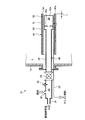
- FIG. 1 is a schematic view showing a combustion burner according to an embodiment of the present invention.
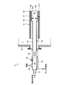
- FIG. 2 is a schematic diagram showing the operation of the combustion burner of the present embodiment.
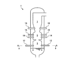
- FIG. 3 is a longitudinal sectional view of the coal gasifier furnace of the present embodiment.
- FIG. 4 is a cross-sectional view taken along line AA of FIG. 3 showing a cross-sectional view of the coal gasification furnace vessel of the present embodiment.
- FIG. 1 is a schematic diagram showing a combustion burner according to one embodiment of the present invention
- FIG. 2 is a schematic diagram showing the operation of the combustion burner of this embodiment
- FIG. 3 is a diagram of a coal gasifier vessel of this embodiment.
- FIG. 4 is a longitudinal sectional view
- FIG. 4 is an AA sectional view of FIG. 3 showing a transverse sectional view of the coal gasification furnace vessel of the present embodiment.
- the gasification furnace (pressurization type gasification furnace) 1 has a light combustion chamber 3, a combustor part 5, and a reductor part 7 in order from the bottom.
- the light combustion chamber 3 is provided with a starting burner (combustion burner) 12.
- the activation burner 12 is configured by arranging an ignition torch 42 inside the burner body 41.
- the combustor unit 5 is provided with a pulverized coal burner 14 and a char burner 16.
- the reductor unit 7 is provided with a gasification burner 18.
- the combustor part 5 which became more than coal ignition temperature becomes the high temperature by burning the air and coal which become a gasifying agent thrown into only this combustor part 5, and the ash in coal melts and flows down, and the combustor part 5
- the reductor unit 7 can efficiently convert coal into gas by the reaction between the hot gas rising from the combustor unit 5 and the newly input coal.
- the activation burner 12 includes a burner body 41 and an ignition torch 42.
- the burner body 41 can blow a fuel gas in which fuel and air are mixed.
- the ignition torch 42 is disposed inside the burner body 41 and can transmit a flame from the base end portion and send it out from the tip end portion.
- the burner body 41 can be ignited by the flame of the ignition torch 42 to form a flame as the activation burner 12.
- the burner body 41 is provided with a fuel gas passage 53 formed between the outer cylinder 51 and the inner cylinder 52, and a nozzle 54 capable of blowing fuel gas into the gasification furnace 1 is formed at the tip.
- the outer cylinder 51 and the inner cylinder 52 have a cylindrical shape, are fixed to the furnace wall 1a, and are provided with a gas fuel supply section and a combustion air supply section (not shown) at the base end.
- the ignition torch 42 is disposed inside the burner body 41 and is fixed to the furnace wall 1a in a cylindrical shape.
- the ignition torch 42 includes, in order from the base end outside the gasification furnace 1, a mixing chamber 20 in which fuel and combustion air are mixed, an ignition unit 22, an on-off valve 24, a combustion tube 26, and a flame holding unit. 28 is provided as a main part.
- the mixing chamber 20 is provided with a fuel supply port 30 and a combustion air supply port 31. Therefore, the fuel and the combustion air are sufficiently mixed in the mixing chamber 20 and ignited by the ignition unit 22 provided on the downstream side of the fuel flow.
- ignition unit 22 ignition by a glow plug or an igniter is preferably used.
- the mixing chamber 20 and the ignition part 22 are arranged outside the gasifier 1.
- An on-off valve 24 is provided between the mixing chamber 20 and the combustion pipe 26 extending over the gasification furnace 1.
- the on-off valve 24 is provided outside the gasification furnace 1.
- the on-off valve 24 can open or close the passage to flow or block the fluid between the ignition unit 22 side and the gasification furnace 1 side.
- the combustion tube 26 is provided with a flame holding portion 28 having an inner diameter larger than that of the combustion tube 26 at the tip, and a flame holding plate 28 a is fixed inside the flame holding portion 28.
- the assist fuel pipe 32 through which the assist fuel flows is inserted from the outside of the furnace into the furnace, passes through the side of the combustion pipe 26, and extends to the flame holding section 28.
- the assist fuel pipe 32 can supply assist fuel to the flame holding section 28.
- the activation burner 12 of the present embodiment described above operates as follows.
- the ignition torch 42 first supplies only the combustion air from the combustion air supply port 31 and ignites the ignition unit 22 before ignition. After the temperature of the ignition unit 22 rises to the ignition temperature, fuel is supplied from the fuel supply port 30 into the mixing chamber 20, and the fuel and combustion air are mixed.
- the air ratio at this time (actual input air amount / theoretical required air amount) is about 0.4 to 0.7.
- the mixed fuel gas is ignited by the ignition unit 22 to form a flame.
- the flame passes through the opened on-off valve 24 and propagates through the combustion pipe 26.
- the flame that reaches the flame holding portion 28 from the combustion tube 26 becomes a main flame in the flame holding portion 28 and burns.
- the assist fuel is supplied from the assist fuel pipe 32 to the flame holder 28. As a result, the main fire that has grown in the flame holding section 28 is stably burned.
- a fuel gas in which air and fuel are mixed is blown into the gasification furnace 1 from the nozzle 54. Since the ignition torch 42 flows out from the flame holding portion 28 when the main flame of the flame holding portion 28 is stabilized, the fuel gas blown into the gasification furnace 1 from the burner body 41 is discharged from the ignition torch 42. The starting burner 12 is ignited by the flame.
- the gasification furnace 1 is constantly maintained as a high-pressure state in addition to a high-temperature condition in order to mainly promote the combustion gasification reaction of char. Therefore, when inspecting the ignition torch 42, it takes time to depressurize all facilities of the gasifier during the pressurization operation to normal pressure. Will bear.
- the on-off valve 24 provided on the downstream side of the fuel flow of the ignition unit 22 provided outside the gasifier 1 is used. That is, when trouble occurs in the ignition torch 42 during torch ignition or during start-up burner operation and inspection is required, the on-off valve 24 is closed in that state. Thereby, since the inside of the gasification furnace 1 and the ignition part 22 side are interrupted
- the tip end portion 42a of the ignition torch 42 is disposed on the base end side (outer side of the furnace) with respect to the tip end portion 41a of the burner body 41.
- the distal end portion 42 a of the ignition torch 42 is disposed closer to the proximal end portion than the distal end portion 41 a of the burner body 41 when the ignition torch 42 is not operated.
- the ignition torch 42 is not in operation, before the flame is propagated from the base end portion to the tip end portion of the ignition torch 42 or after the ignition of the fuel gas from the burner body 41 is stopped, the flame propagation by the ignition torch 42 is stopped. It is.
- the tip end portion 42 a of the ignition torch 42 is arranged at substantially the same position as the tip end portion 41 a of the burner body 41.
- the flame is propagated from the base end portion to the tip end portion of the ignition torch 42.
- the position of the tip 42a when the ignition torch 42 is not operated is set in consideration of the length of the pipe (combustion pipe 26, etc.) through which the flame propagates. That is, since the ignition torch 42 has a predetermined length, when the flame propagates from the base end portion toward the tip end portion, the base end portion is thermally extended as the base point of the furnace wall 1a, and heat is applied to the tip end portion. It grows. For this reason, the ignition torch 42 is moved backwardly when the ignition torch 42 is not operated so that the tip 42a of the ignition torch 42 is located at substantially the same position as the tip 41a of the burner main body 41 when the flame propagates. Is set.
- the distal end portion 42a of the ignition torch 42 Prior to activation of the activation burner 12, the distal end portion 42a of the ignition torch 42 is positioned on the proximal end side by a retreat distance L with respect to the distal end portion 41a of the burner main body 41.
- the ignition torch 42 when the ignition torch 42 is actuated, the flame propagates from the base end side toward the tip end side, so that the combustion tube 26 is heated to a high temperature, and the thermal elongation increases in the longitudinal direction toward the tip end side. appear.
- the ignition torch 42 has the tip end portion 42 a positioned substantially at the same position as the tip end portion 41 a of the burner body 41. Therefore, the burner main body 41 can ignite the fuel gas blown into the gasification furnace 1 upon receiving the flame from the ignition torch 42 and form a flame as the starter burner 12.
- the ignition torch 42 contracts toward the base end side in the longitudinal direction, and the tip end portion 42a is located at a position retracted from the tip end portion 41a of the burner body 41 as shown in FIG. Therefore, the ignition torch 42 is held at a position where the tip end portion 42a is retracted from the tip end portion 41a of the burner main body 41, so that the heat load due to the burner main body 41k flame is reduced and burnout is prevented. .
- the burner main body 41 capable of injecting fuel gas mixed with fuel and air, the flame burner from the base end portion disposed inside the burner main body 41, and the tip An ignition torch 42 that is fed out from the portion is provided, and the distal end portion 42 a of the ignition torch 42 is disposed on the proximal end side with respect to the distal end portion 41 a of the burner body 41.
- the distal end portion 42a of the ignition torch 42 is located on the proximal end side with respect to the distal end portion 41a of the burner body 41. Therefore, it is possible to reduce the thermal load at the tip end portion 42a of the ignition torch 42 against the flame of the burner body 41, thereby improving the durability and extending the life.
- the distal end portion 42a of the ignition torch 42 is disposed closer to the proximal end portion side than the distal end portion 41a of the burner body 41 when the ignition torch 42 is not operated. Therefore, since the tip of the ignition torch 42 is located in the retracted position when not operating, the thermal load on the tip 42a of the ignition torch 42 can be reduced against the flame of the burner body 41.
- the distal end of the ignition torch 42 Since the part 42a is located at the retracted position, it is possible to reduce the thermal load at the tip 42a of the ignition torch 42 against the flame of the burner body 41.
- the tip end portion 42a of the ignition torch 42 is disposed at substantially the same position as the tip end portion 41a of the burner body 41 when the ignition torch 42 is operated. Accordingly, the ignition torch 42 has the distal end portion 42a positioned substantially at the same position as the distal end portion 41a of the burner main body 41 during operation, and at this time, the flame propagated from the proximal end portion and sent out from the distal end portion, The fuel gas blown from 41 can be appropriately ignited.
- the tip end portion 42a of the ignition torch 42 is located at substantially the same position as the tip end portion 41a of the burner body 41.
- the fuel gas blown from the burner body 41 can be appropriately ignited.
- the position when the ignition torch 42 is not operated is set in consideration of the length of the combustion pipe 26 through which the flame propagates. Therefore, the non-operating position and non-operating position of the ignition torch 42 can be set appropriately.
- the ignition part 22 is provided at the base end part 42 a of the ignition torch 42, and the on-off valve 24 is provided downstream of the ignition part 22 in the fuel flow direction. Therefore, the ignition part 22 can be easily inspected without depending on the state in the gasification furnace 1. Further, by closing the on-off valve 24, the inside of the gasification furnace 1 and the ignition part 22 side can be separated, and as a result, the on-off valve 24 is closed even when inspection is required due to various problems. Thus, the ignition part 22 side can be separated from the gasification furnace 1 and can be easily inspected without depending on the state in the gasification furnace 1.
- the burner body 41 fixed to the furnace wall 1a and capable of blowing fuel gas mixed with fuel and air into the furnace, and the burner body 41 are disposed inside.
- An ignition torch 42 that is fixed to the furnace wall 1a and propagates a flame from the base end portion and sends out from the tip end portion is provided, and the tip end portion 42a of the ignition torch 42 is the base end with respect to the tip end portion 41a of the burner body 41 It is arranged on the part side.
- the combustion burner of this invention was applied to the gasification furnace 1, it is not limited to the gasification furnace 1.
- the ignition torch 42 is composed of the ignition part 22, the on-off valve 24, the combustion pipe 26, and the flame holding part 28, it is not limited to this configuration and arrangement.
Landscapes
- Engineering & Computer Science (AREA)
- Chemical & Material Sciences (AREA)
- Combustion & Propulsion (AREA)
- Mechanical Engineering (AREA)
- General Engineering & Computer Science (AREA)
- Oil, Petroleum & Natural Gas (AREA)
- Organic Chemistry (AREA)
Abstract
Description
1a 火炉壁
12 起動用バーナ(燃焼バーナ)
20 混合室
22 着火部
24 開閉弁
26 燃焼管
28 保炎部
41 バーナ本体
41a 先端部
42 点火トーチ
42a 先端部
Claims (8)
- 燃料と空気を混合した燃料ガスを吹き込み可能なバーナ本体と、
前記バーナ本体の内側に配置されて基端部から火炎を伝播して先端部から送り出す点火トーチと、
を有し、
前記バーナ本体の先端部に対して前記点火トーチの先端部が基端部側に配置される、
ことを特徴とする燃焼バーナ。 - 前記点火トーチの非作動時に、前記点火トーチの先端部が前記バーナ本体の先端部よりも基端部側に配置されることを特徴とする請求項1に記載の燃焼バーナ。
- 前記点火トーチの非作動時とは、前記点火トーチの基端部から先端部に火炎を伝播する前、または、前記バーナ本体からの燃料ガスに点火後に前記点火トーチによる火炎の伝播を停止した後を有することを特徴とする請求項2に記載の燃焼バーナ。
- 前記点火トーチの作動時に、前記点火トーチの先端部が前記バーナ本体の先端部とほぼ同位置に配置されることを特徴とする請求項1に記載の燃焼バーナ。
- 前記点火トーチの作動時とは、前記点火トーチの基端部から先端部に火炎を伝播するときを有することを特徴とする請求項4に記載の燃焼バーナ。
- 前記点火トーチの非作動時における先端部の位置は、火炎が伝播する配管の長さを考慮して設定されることを特徴とする請求項1から5のいずれか一つに記載の燃焼バーナ。
- 前記点火トーチの基端部に着火部が設けられ、前記着火部の燃料流れ方向の下流側に開閉弁が設けられることを特徴とする請求項1から6のいずれか一つに記載の燃焼バーナ。
- 火炉壁に固定されて燃料と空気を混合した燃料ガスを火炉内に吹き込み可能なバーナ本体と、
前記バーナ本体の内側に配置されるように前記火炉壁に固定されて基端部から火炎を伝播して先端部から送り出す点火トーチと、
を有し、
前記バーナ本体の先端部に対して前記点火トーチの先端部が基端部側に配置される、
ことを特徴とする加圧型ガス化炉。
Priority Applications (3)
| Application Number | Priority Date | Filing Date | Title |
|---|---|---|---|
| CN201380067531.6A CN104903651B (zh) | 2012-12-26 | 2013-11-28 | 燃烧炉及加压型煤气化炉 |
| KR1020157016778A KR101742409B1 (ko) | 2012-12-26 | 2013-11-28 | 연소버너 및 가압형 가스화 노 |
| US14/654,681 US20150345788A1 (en) | 2012-12-26 | 2013-11-28 | Combustion burner and pressurized gasification furnace |
Applications Claiming Priority (2)
| Application Number | Priority Date | Filing Date | Title |
|---|---|---|---|
| JP2012283246A JP5575221B2 (ja) | 2012-12-26 | 2012-12-26 | 燃焼バーナ及び加圧型ガス化炉 |
| JP2012-283246 | 2012-12-26 |
Publications (1)
| Publication Number | Publication Date |
|---|---|
| WO2014103607A1 true WO2014103607A1 (ja) | 2014-07-03 |
Family
ID=51020701
Family Applications (1)
| Application Number | Title | Priority Date | Filing Date |
|---|---|---|---|
| PCT/JP2013/082067 Ceased WO2014103607A1 (ja) | 2012-12-26 | 2013-11-28 | 燃焼バーナ及び加圧型ガス化炉 |
Country Status (5)
| Country | Link |
|---|---|
| US (1) | US20150345788A1 (ja) |
| JP (1) | JP5575221B2 (ja) |
| KR (1) | KR101742409B1 (ja) |
| CN (1) | CN104903651B (ja) |
| WO (1) | WO2014103607A1 (ja) |
Cited By (2)
| Publication number | Priority date | Publication date | Assignee | Title |
|---|---|---|---|---|
| CN114321901A (zh) * | 2020-10-12 | 2022-04-12 | 北京动力机械研究所 | 一种提液式火炬燃烧系统及其燃烧方法 |
| CN115468186A (zh) * | 2022-08-31 | 2022-12-13 | 常德市三一机械有限公司 | 燃烧器点火设备、点火方法及沥青站 |
Families Citing this family (15)
| Publication number | Priority date | Publication date | Assignee | Title |
|---|---|---|---|---|
| US20170074509A1 (en) * | 2015-09-11 | 2017-03-16 | Green Air Burner Systems, LLC | Hydrocarbon Burner |
| US11473505B2 (en) | 2020-11-04 | 2022-10-18 | Delavan Inc. | Torch igniter cooling system |
| US11608783B2 (en) | 2020-11-04 | 2023-03-21 | Delavan, Inc. | Surface igniter cooling system |
| US11692488B2 (en) | 2020-11-04 | 2023-07-04 | Delavan Inc. | Torch igniter cooling system |
| US11635027B2 (en) | 2020-11-18 | 2023-04-25 | Collins Engine Nozzles, Inc. | Fuel systems for torch ignition devices |
| US11421602B2 (en) | 2020-12-16 | 2022-08-23 | Delavan Inc. | Continuous ignition device exhaust manifold |
| US11226103B1 (en) | 2020-12-16 | 2022-01-18 | Delavan Inc. | High-pressure continuous ignition device |
| US11486309B2 (en) * | 2020-12-17 | 2022-11-01 | Delavan Inc. | Axially oriented internally mounted continuous ignition device: removable hot surface igniter |
| US11754289B2 (en) | 2020-12-17 | 2023-09-12 | Delavan, Inc. | Axially oriented internally mounted continuous ignition device: removable nozzle |
| US11635210B2 (en) | 2020-12-17 | 2023-04-25 | Collins Engine Nozzles, Inc. | Conformal and flexible woven heat shields for gas turbine engine components |
| US12092333B2 (en) | 2020-12-17 | 2024-09-17 | Collins Engine Nozzles, Inc. | Radially oriented internally mounted continuous ignition device |
| US11680528B2 (en) | 2020-12-18 | 2023-06-20 | Delavan Inc. | Internally-mounted torch igniters with removable igniter heads |
| US11209164B1 (en) | 2020-12-18 | 2021-12-28 | Delavan Inc. | Fuel injector systems for torch igniters |
| US11286862B1 (en) * | 2020-12-18 | 2022-03-29 | Delavan Inc. | Torch injector systems for gas turbine combustors |
| US11773784B2 (en) * | 2021-10-12 | 2023-10-03 | Collins Engine Nozzles, Inc. | Fuel injectors with torch ignitors |
Citations (4)
| Publication number | Priority date | Publication date | Assignee | Title |
|---|---|---|---|---|
| JPH01267325A (ja) * | 1988-04-20 | 1989-10-25 | Central Res Inst Of Electric Power Ind | 低カロリーガス用ガスタービン燃焼器 |
| JPH02254225A (ja) * | 1989-03-27 | 1990-10-15 | Nippon Furnace Kogyo Kaisha Ltd | パイロットガスバーナ |
| JPH11108312A (ja) * | 1997-10-09 | 1999-04-23 | Ishikawajima Harima Heavy Ind Co Ltd | 点火バーナ装置 |
| JP2011117713A (ja) * | 2009-10-29 | 2011-06-16 | Mitsubishi Heavy Ind Ltd | 点火トーチ及び加圧型ガス化炉 |
Family Cites Families (16)
| Publication number | Priority date | Publication date | Assignee | Title |
|---|---|---|---|---|
| US1652524A (en) * | 1927-12-13 | Heater lighter | ||
| US2882735A (en) * | 1951-04-27 | 1959-04-21 | Surface Combustion Corp | Safety pilot assembly for burners |
| US3455640A (en) * | 1967-07-26 | 1969-07-15 | Essex Wire Corp | Compensated pilot burner |
| US3642060A (en) * | 1970-03-16 | 1972-02-15 | Bethlehem Steel Corp | Water-cooled apparatus |
| DE2942726A1 (de) * | 1979-10-23 | 1981-05-07 | Krupp-Koppers Gmbh, 4300 Essen | Brenner fuer gasfoermige oder fluessige brennstoffe |
| JPS6423004A (en) * | 1987-07-17 | 1989-01-25 | Mitsubishi Heavy Ind Ltd | Burner device for high pressure combustion furnace |
| KR100728834B1 (ko) * | 2000-09-27 | 2007-06-15 | 주식회사 포스코 | 직화로의 노즐 믹서 버너 |
| KR20020044432A (ko) * | 2000-12-06 | 2002-06-15 | 이구택 | 연료와 공기의 혼합을 개선한 소둔로 점화장치 |
| US6951455B2 (en) * | 2004-02-25 | 2005-10-04 | Jacob Goldman | Gas burner |
| CN2856752Y (zh) * | 2005-12-27 | 2007-01-10 | 郭秀峰 | 微油枪伸缩机构 |
| CN201016479Y (zh) * | 2006-10-13 | 2008-02-06 | 上海齐耀动力技术有限公司 | 一种热气机用燃烧器 |
| CN201014505Y (zh) * | 2006-11-20 | 2008-01-30 | 艾佩克斯科技(北京)有限公司 | 微油枪的伸缩机构 |
| US9127842B2 (en) * | 2009-05-27 | 2015-09-08 | Siemens Aktiengesellschaft | Burner, operating method and assembly method |
| CN201680366U (zh) * | 2010-03-24 | 2010-12-22 | 杭州燃油锅炉厂 | 水煤浆燃烧器 |
| WO2012073299A1 (ja) * | 2010-11-29 | 2012-06-07 | 三菱重工業株式会社 | 点火トーチおよびこれを備えた加圧型ガス化炉 |
| GB201419053D0 (en) * | 2014-10-27 | 2014-12-10 | Rolls Royce Plc | Igniter Assembly |
-
2012
- 2012-12-26 JP JP2012283246A patent/JP5575221B2/ja not_active Expired - Fee Related
-
2013
- 2013-11-28 KR KR1020157016778A patent/KR101742409B1/ko not_active Expired - Fee Related
- 2013-11-28 WO PCT/JP2013/082067 patent/WO2014103607A1/ja not_active Ceased
- 2013-11-28 CN CN201380067531.6A patent/CN104903651B/zh not_active Expired - Fee Related
- 2013-11-28 US US14/654,681 patent/US20150345788A1/en not_active Abandoned
Patent Citations (4)
| Publication number | Priority date | Publication date | Assignee | Title |
|---|---|---|---|---|
| JPH01267325A (ja) * | 1988-04-20 | 1989-10-25 | Central Res Inst Of Electric Power Ind | 低カロリーガス用ガスタービン燃焼器 |
| JPH02254225A (ja) * | 1989-03-27 | 1990-10-15 | Nippon Furnace Kogyo Kaisha Ltd | パイロットガスバーナ |
| JPH11108312A (ja) * | 1997-10-09 | 1999-04-23 | Ishikawajima Harima Heavy Ind Co Ltd | 点火バーナ装置 |
| JP2011117713A (ja) * | 2009-10-29 | 2011-06-16 | Mitsubishi Heavy Ind Ltd | 点火トーチ及び加圧型ガス化炉 |
Cited By (3)
| Publication number | Priority date | Publication date | Assignee | Title |
|---|---|---|---|---|
| CN114321901A (zh) * | 2020-10-12 | 2022-04-12 | 北京动力机械研究所 | 一种提液式火炬燃烧系统及其燃烧方法 |
| CN115468186A (zh) * | 2022-08-31 | 2022-12-13 | 常德市三一机械有限公司 | 燃烧器点火设备、点火方法及沥青站 |
| CN115468186B (zh) * | 2022-08-31 | 2024-03-22 | 常德市三一机械有限公司 | 燃烧器点火设备、点火方法及沥青站 |
Also Published As
| Publication number | Publication date |
|---|---|
| KR101742409B1 (ko) | 2017-05-31 |
| KR20150088847A (ko) | 2015-08-03 |
| JP2014126278A (ja) | 2014-07-07 |
| US20150345788A1 (en) | 2015-12-03 |
| JP5575221B2 (ja) | 2014-08-20 |
| CN104903651A (zh) | 2015-09-09 |
| CN104903651B (zh) | 2017-02-22 |
Similar Documents
| Publication | Publication Date | Title |
|---|---|---|
| JP5575221B2 (ja) | 燃焼バーナ及び加圧型ガス化炉 | |
| CN103069217B (zh) | 点火嘴及具备该点火嘴的加压型气化炉 | |
| JP5205203B2 (ja) | スラグ溶融バーナ装置 | |
| JP2010270988A (ja) | 燃焼装置 | |
| JP5216076B2 (ja) | スラグ溶融酸素バーナーを用いた溶融炉 | |
| AR068220A1 (es) | Un metodo para anclar una llama piloto con salida de calor elevado a una boquilla de piloto asociada con una caldera de vapor alimentada a carbon para hornos industriales, un metodo para precalentar el horno, un metodo para generar una llama de piloto y un aparato para precalentar el horno | |
| TWI712762B (zh) | 燃燒器裝置及加熱處理設備 | |
| KR101048034B1 (ko) | 시멘트 소성로용 버너장치 | |
| JP5517886B2 (ja) | 点火トーチ及び加圧型ガス化炉 | |
| JP4910632B2 (ja) | 管状火炎バーナおよびラジアントチューブ式加熱装置 | |
| JP5459836B2 (ja) | 廃棄物ガス化溶融炉の燃焼室の助燃バーナ用のバーナタイル | |
| TW201907124A (zh) | 蓄熱式燃燒設備 | |
| US9039408B2 (en) | Combustor with a combustion region between an inner pipe and outer pipe with an ignition device upstream of the combustion region | |
| KR100761888B1 (ko) | 고온 용융로용 버너 | |
| JP5981696B2 (ja) | ガス化溶融設備の溶融炉 | |
| JP2008138901A (ja) | 低揮発分燃料用バーナ装置 | |
| JP6430339B2 (ja) | フレームレス燃焼装置 | |
| KR101152401B1 (ko) | 합성가스를 이용한 저열량가스 연소 장치 및 그 방법 | |
| KR100825664B1 (ko) | 폐유의 완전 연소 버너 및 방법 | |
| JP2008249280A (ja) | ガスバーナ | |
| JP6284165B1 (ja) | パイロットバーナー点火装置 | |
| KR20190061986A (ko) | 액체연료 미립화의 최적화 구조를 가지는 대용량 산소버너 | |
| JP2010168951A (ja) | ガス化発電プラントの安定運転方法及びガス化発電プラント | |
| JPH0665719U (ja) | 焼却室用点火装置 |
Legal Events
| Date | Code | Title | Description |
|---|---|---|---|
| 121 | Ep: the epo has been informed by wipo that ep was designated in this application |
Ref document number: 13868319 Country of ref document: EP Kind code of ref document: A1 |
|
| WWE | Wipo information: entry into national phase |
Ref document number: 14654681 Country of ref document: US |
|
| ENP | Entry into the national phase |
Ref document number: 20157016778 Country of ref document: KR Kind code of ref document: A |
|
| NENP | Non-entry into the national phase |
Ref country code: DE |
|
| 122 | Ep: pct application non-entry in european phase |
Ref document number: 13868319 Country of ref document: EP Kind code of ref document: A1 |