WO2014103538A1 - キャップ検査装置 - Google Patents
キャップ検査装置 Download PDFInfo
- Publication number
- WO2014103538A1 WO2014103538A1 PCT/JP2013/080420 JP2013080420W WO2014103538A1 WO 2014103538 A1 WO2014103538 A1 WO 2014103538A1 JP 2013080420 W JP2013080420 W JP 2013080420W WO 2014103538 A1 WO2014103538 A1 WO 2014103538A1
- Authority
- WO
- WIPO (PCT)
- Prior art keywords
- cap
- container
- mouth
- gap
- inspection
- Prior art date
Links
Images


Classifications
-
- B—PERFORMING OPERATIONS; TRANSPORTING
- B67—OPENING, CLOSING OR CLEANING BOTTLES, JARS OR SIMILAR CONTAINERS; LIQUID HANDLING
- B67B—APPLYING CLOSURE MEMBERS TO BOTTLES JARS, OR SIMILAR CONTAINERS; OPENING CLOSED CONTAINERS
- B67B3/00—Closing bottles, jars or similar containers by applying caps
- B67B3/26—Applications of control, warning, or safety devices in capping machinery
- B67B3/262—Devices for controlling the caps
- B67B3/264—Devices for controlling the caps positioning of the caps
-
- G—PHYSICS
- G01—MEASURING; TESTING
- G01B—MEASURING LENGTH, THICKNESS OR SIMILAR LINEAR DIMENSIONS; MEASURING ANGLES; MEASURING AREAS; MEASURING IRREGULARITIES OF SURFACES OR CONTOURS
- G01B11/00—Measuring arrangements characterised by the use of optical techniques
- G01B11/14—Measuring arrangements characterised by the use of optical techniques for measuring distance or clearance between spaced objects or spaced apertures
-
- G—PHYSICS
- G01—MEASURING; TESTING
- G01B—MEASURING LENGTH, THICKNESS OR SIMILAR LINEAR DIMENSIONS; MEASURING ANGLES; MEASURING AREAS; MEASURING IRREGULARITIES OF SURFACES OR CONTOURS
- G01B11/00—Measuring arrangements characterised by the use of optical techniques
- G01B11/24—Measuring arrangements characterised by the use of optical techniques for measuring contours or curvatures
- G01B11/245—Measuring arrangements characterised by the use of optical techniques for measuring contours or curvatures using a plurality of fixed, simultaneously operating transducers
-
- G—PHYSICS
- G01—MEASURING; TESTING
- G01N—INVESTIGATING OR ANALYSING MATERIALS BY DETERMINING THEIR CHEMICAL OR PHYSICAL PROPERTIES
- G01N21/00—Investigating or analysing materials by the use of optical means, i.e. using sub-millimetre waves, infrared, visible or ultraviolet light
- G01N21/84—Systems specially adapted for particular applications
- G01N21/88—Investigating the presence of flaws or contamination
- G01N21/90—Investigating the presence of flaws or contamination in a container or its contents
- G01N21/909—Investigating the presence of flaws or contamination in a container or its contents in opaque containers or opaque container parts, e.g. cans, tins, caps, labels
-
- G—PHYSICS
- G01—MEASURING; TESTING
- G01N—INVESTIGATING OR ANALYSING MATERIALS BY DETERMINING THEIR CHEMICAL OR PHYSICAL PROPERTIES
- G01N21/00—Investigating or analysing materials by the use of optical means, i.e. using sub-millimetre waves, infrared, visible or ultraviolet light
- G01N21/84—Systems specially adapted for particular applications
- G01N21/88—Investigating the presence of flaws or contamination
- G01N21/90—Investigating the presence of flaws or contamination in a container or its contents
Definitions
- the present invention relates to an apparatus for inspecting whether a cap is correctly screwed into a mouth portion of a container such as a PET bottle (PET bottle).
- PET bottle PET bottle
- a screw-type cap As a cap for closing the mouth of a container such as a plastic bottle filled with a soft drink, a screw-type cap is widely used.
- a screw structure that engages with each other is formed on the inner peripheral surface of the cap and the outer peripheral surface of the container mouth, and the cap is attached to the container mouth by screwing the cap into the container mouth.
- a cap inspection device described in Patent Document 1 is known as a device for inspecting whether or not a screw-in type cap is correctly attached to a container mouth.
- This cap inspection device acquires an image of a cap screwed into a container, and from the acquired image, measures a distance between a lower end portion on both sides of the cap and a flange formed on a container mouth portion, and determines the distance of these distances. Based on the measurement result, it is configured to determine whether or not the cap is correctly screwed into the container mouth.
- the conventional cap inspection apparatus is configured to acquire images of the cap and the container from only one direction, the distance between the cap and the flange can be changed depending on the angle of the cap. For example, if the mouth of the container itself is bent or if the entire cap is tilted, an image acquired from one direction may not correctly represent the screwed state of the cap.
- Patent Document 1 it is disclosed that the cap is imaged by three image generation units arranged at intervals of approximately 120 °, but the three images obtained by the three image generation units are individually provided. As a result, the result is the same as the case where the cap image is acquired from only one direction. As described above, in the conventional cap inspection apparatus, it is difficult to accurately inspect the screwed state of the cap.
- the present invention has been made to solve the above-described conventional problems, and provides a cap inspection device capable of accurately inspecting whether or not a cap is correctly screwed into a container mouth portion. Objective.
- one aspect of the present invention is a cap inspection device for inspecting a screwed state of a cap into a mouth portion of a container, wherein images of the cap and the mouth portion of the container are viewed from multiple directions.
- the imaging processing unit receives an image from each of the plurality of imaging devices, and determines a size of a gap between the cap and a support ring formed at a mouth of the container from the image. Calculating a plurality of gap index values, calculating a sum value of the plurality of gap index values, and determining whether the cap is correctly screwed into the mouth of the container based on the sum value. And features.
- the plurality of imagers are an odd number of imagers.
- the gap index value is an area of a gap between the cap and the support ring or a distance between the cap and the support ring.
- the inspection processing unit is configured such that the total value or an average value obtained by dividing the total value by the number of the plurality of imaging devices is equal to or less than a predetermined first threshold value. It is determined that the cap is correctly screwed into the mouth of the container. In a preferred aspect of the present invention, the inspection processing unit is configured such that the total value or an average value obtained by dividing the total value by the number of the plurality of imaging devices is equal to or greater than a predetermined second threshold value. It is determined that the cap is correctly screwed into the mouth of the container.
- the inspection processing unit is configured such that the cap or the average value obtained by dividing the sum by the number of the plurality of imaging devices is within a predetermined range. Is determined to be correctly screwed into the mouth of the container.
- the illuminator further includes a plurality of illuminators that illuminate the cap from multiple directions, and the plurality of illuminators are arranged so as to face the plurality of imaging devices, respectively.
- images of the cap are acquired from at least three directions, and the screwed state of the cap is determined based on the sum of the gap index values between the cap and the support ring obtained from these images.
- the gap index values By summing the gap index values in this way, the gap variation existing along the circumferential direction of the cap is offset. Therefore, the cap inspection apparatus according to the present invention can accurately determine whether or not the cap is correctly screwed into the container mouth.
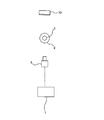
- FIG. 1 is a plan view showing an embodiment of a cap inspection device according to the present invention.
- the cap inspection apparatus includes a plurality of imaging devices 5 that acquire images of the mouths of the cap 1 and the container 2 from multiple directions, and an inspection that processes the plurality of images acquired by these imaging devices 5.
- a processing unit 7. The containers 2 are sequentially transported to the cap inspection device by the transport conveyor 9 with the cap 1 screwed into the mouth. While the container 2 is moved by the transport conveyor 9, the image pickup device 5 acquires an image of the mouth of the container 2 on the transport conveyor 9 and the cap 1 attached thereto. The container 2 is transported from the cap inspection device by the transport conveyor 9 as it is.
- three image pickup devices 5 are arranged around the container 2 at equal intervals, that is, at intervals of 120 °. These image pickup devices 5 face the cap 1 on the container 2 and are configured to acquire images of the mouths of the cap 1 and the container 2 from three directions.
- a camera having an image sensor such as a CCD or a CMOS is used for each imaging device 5.
- the cap inspection apparatus further includes a plurality of illuminators 10 that illuminate the container 2 from multiple directions.
- the same number of illuminators 10 as the imaging device 5 are arranged.
- three illuminators 10 are provided corresponding to the three imaging devices 5, and these three illuminators 10 are arranged so as to face the three imaging devices 5, respectively.
- the container 2 and the cap 1 are located between a pair of the image pickup device 5 and the illuminator 10.
- This predetermined imaging position is a position where the distances from the cap 1 to the plurality of imaging devices 5 are equal to each other.
- the imaging device 5 facing the illuminator 10 images the mouth of the cap 1 and the container 2.
- the three image pickup devices 5 simultaneously image the cap 1 and the mouth of the container 2 from multiple directions. Therefore, three images are acquired for each cap 1.
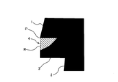
- FIG. 2 is a diagram illustrating an image of the cap 1 acquired by the imaging device 5. As can be seen from FIG. 2, an image acquired in a state where light is illuminated from the back side of the cap 1 is a silhouette image. In this silhouette image, a part of the mouth of the cap 1 and the container 2 is shown.
- a support ring (flange) 3 protruding outward in the radial direction is formed at the mouth of the container 2.
- the cap 1 is located above the support ring 3.
- an appropriate gap is formed between the lower end of the cap 1 and the support ring 3.
- the inspection processing unit 7 inspects the screwed state of the cap 1 into the mouth of the container 2 based on the size of the gap between the lower end of the cap 1 and the support ring 3.
- FIG. 3 is an enlarged view showing the gap 4 between the lower end of the cap 1 and the support ring 3 shown in FIG.
- the inspection processing unit 7 specifies the position of the lower end corner portion P of the cap 1 on the image, and draws a boundary line R from the specified lower end corner portion P vertically downward until reaching the support ring 3.
- a region (indicated by oblique lines) through which light inside the boundary line R passes is a region representing the gap 4.
- the inspection processing unit 7 calculates the area of the region specified in this way. For example, the inspection processing unit 7 can calculate the area from the number of pixels occupying the specified region.
- the area value thus obtained is a gap index value indicating the size of the gap 4 between the cap 1 and the support ring 3.
- the inspection processing unit 7 receives three images acquired by the three image pickup devices 5, calculates two gap index values for each of the three images, and acquires a total of six gap index values. Further, the inspection processing unit 7 calculates a sum value of these six gap index values, and determines whether or not the cap 1 is correctly screwed into the mouth of the container 2 based on the obtained sum value. More specifically, the inspection processing unit 7 determines that the cap 1 is correctly screwed into the mouth of the container 2 when the total value is equal to or less than the first threshold value, and the total value is the first threshold value. If it is larger than that, it is determined that the cap 1 is not correctly screwed into the mouth of the container 2.
- the first threshold value corresponds to an upper limit value indicating a state in which the cap 1 is correctly screwed into the mouth of the container 2, and is set in advance.
- an average value of gap index values per image may be used. More specifically, the inspection processing unit 7 calculates an average value by dividing the obtained total value by 3 that is the number of the image pickup devices 5, and the average value is equal to or less than a predetermined first threshold value. In the case of, it is determined that the cap 1 is correctly screwed into the mouth of the container 2, and when the average value is larger than the first threshold value, it is determined that the cap 1 is not correctly screwed into the mouth of the container 2. To do.
- FIG. 4 is a graph showing an average value of the gap index values.
- the vertical axis represents the average value of the gap index values
- the horizontal axis represents the circumferential angle (0 ° to 360 °) of the cap 1.
- FIG. 4 shows four average values calculated for each of the four caps 1a to 1d.
- the graph shown in FIG. 4 represents the result of imaging the mouth of the cap 1 and the container 2 a plurality of times at a certain time interval while rotating the cap 1 and the container 2 around the axis for the purpose of the test. Yes.
- images of the mouths of the cap 1 and the container 2 are acquired without rotating the cap 1 and the container 2.
- FIG. 5 is a graph showing a gap index value calculated from an image acquired by one imaging device 5 as a comparative example.
- the graph shown in FIG. 5 is obtained by the cap inspection apparatus shown in FIG.
- the cap inspection apparatus shown in FIG. 6 is composed of a pair of imaging device 5 and illuminator 10.
- the comparison result between the first threshold value and the gap index value can vary depending on the angle of the cap 1. For example, when the first threshold value is set to 4000, it is determined that the screwed state of the cap 1b is good or bad depending on the angle when the image is acquired. In the graph shown in FIG. 4, when the first threshold value is set to 4000, it is determined that the screwed state of the cap 1b is defective over the entire angle range, and the screwed state of the cap 1c is determined to be good. .
- FIG. 7 is a graph schematically showing the size of the gap between the cap 1 and the support ring 3. Note that the graph shown in FIG. 7 is an explanatory graph, and the value on the vertical axis does not accurately reflect the size of the gap. In FIG. 7, the sum of the values on the vertical axis at angles of 0 °, 120 °, and 240 ° is 0.
- the cap inspection apparatus acquires three images using the three imaging devices 5 arranged at intervals of 120 °, and the cap 1 and the support ring 3 are obtained from these images.
- the size of the gap can be accurately determined. That is, by adding the gap index values, the gaps existing along the circumferential direction of the cap 1 are offset. Therefore, the cap inspection apparatus can accurately determine whether or not the cap 1 is correctly screwed into the mouth of the container 2.
- the number of image pickup devices 5 is not limited to this embodiment, and more image pickup devices 5 may be used. It is preferable to arrange an odd number of image pickup devices 5 around the container 2 at equal intervals. This is because an odd number of image pickup devices 5 are arranged around the container 2 at equal intervals so that images of gaps at different locations of the cap 1 can be acquired, whereas an even number of image pickup devices 5 are used. This is because, when arranged around the container 2 at equal intervals, the two imaging devices 5 arranged symmetrically acquire images of gaps at substantially the same location of the cap 1.
- the inspection processing unit 7 may determine excessive screwing of the cap 1 using the second threshold value. Specifically, the inspection processing unit 7 determines that the cap 1 is correctly screwed into the mouth portion of the container 2 when the average value of the gap index value is equal to or greater than the second threshold value, and the gap index. If the average value is less than the second threshold, the cap 1 is screwed too tightly into the mouth of the container 2, i.e. the cap 1 is not screwed correctly into the mouth of the container 2. judge.
- the second threshold value corresponds to a lower limit value indicating a state in which the cap 1 is correctly screwed into the mouth portion of the container 2, and is set in advance.
- the inspection processing unit 7 may determine both the insufficient screwing of the cap 1 and the excessive screwing of the cap 1 using the allowable range of the average value of the gap index values. Specifically, the inspection processing unit 7 determines that the cap 1 is correctly screwed into the mouth portion of the container 2 when the average value of the gap index values is within a range set in advance as the allowable range, When the average value of the gap index values is not within the above range, it is determined that the cap 1 is not screwed correctly into the mouth of the container 2.
- the screwed state may be determined using the total value of the gap index values as they are. In either case, it is possible to improve the accuracy of the inspection of the screwed state of the cap 1 in the same manner. Further, as the gap index value, the distance between the lower end of the cap 1 and the support ring 3 may be used instead of the area of the gap. Even in this case, the same effect can be obtained.
- the cap inspection apparatus according to the present invention can be suitably used for inspection of a screw-in type cap attached to a PET bottle (PET bottle).
- PET bottle PET bottle
- the present invention can also be applied to the inspection of screwed caps mounted on containers other than PET bottles.
- the image acquired by the cap inspection apparatus according to the present invention can be commonly used for another inspection apparatus that determines an abnormality in the outer shape of the cap.
- the present invention can be used for an apparatus for inspecting whether a cap is screwed correctly into the mouth of a container such as a PET bottle (PET bottle).
- a container such as a PET bottle (PET bottle).
Abstract
Description
本発明の好ましい態様は、前記隙間指標値は、前記キャップと前記サポートリングとの隙間の面積または前記キャップと前記サポートリングとの距離であることを特徴とする。
本発明の好ましい態様は、前記検査処理部は、前記合算値、または前記合算値を前記複数の撮像機の台数で割り算することで得られる平均値が所定の第2しきい値以上の場合は、前記キャップが前記容器の口部に正しくねじ込まれていると判定することを特徴とする。
本発明の好ましい態様は、前記キャップを多方向から照らす複数の照明器をさらに備え、前記複数の照明器は、前記複数の撮像機にそれぞれ対向するように配置されていることを特徴とする。
2 容器
3 サポートリング
4 隙間
5 撮像機
7 検査処理部
9 搬送コンベヤ
10 照明器
Claims (7)
- 容器の口部へのキャップのねじ込み状態を検査するキャップ検査装置であって、
前記キャップおよび前記容器の口部の画像を多方向から取得する複数の撮像機と、
前記複数の撮像機によって取得された複数の画像を処理する検査処理部とを備え、
前記複数の撮像機は、前記容器の周囲に等間隔に配列された少なくとも3台の撮像機であり、
前記検査処理部は、
前記複数の撮像機のそれぞれから画像を受け取り、
前記画像から、前記キャップと前記容器の口部に形成されたサポートリングとの隙間の大きさを示す複数の隙間指標値を算出し、
前記複数の隙間指標値の合算値を算出し、
前記合算値に基づいて、前記キャップが前記容器の口部に正しくねじ込まれているか否かを判定することを特徴とするキャップ検査装置。 - 前記複数の撮像機は、奇数台の撮像機であることを特徴とする請求項1に記載のキャップ検査装置。
- 前記隙間指標値は、前記キャップと前記サポートリングとの隙間の面積または前記キャップと前記サポートリングとの距離であることを特徴とする請求項1または2に記載のキャップ検査装置。
- 前記検査処理部は、前記合算値、または前記合算値を前記複数の撮像機の台数で割り算することで得られる平均値が所定の第1しきい値以下の場合は、前記キャップが前記容器の口部に正しくねじ込まれていると判定することを特徴とする請求項1乃至3のいずれか一項に記載のキャップ検査装置。
- 前記検査処理部は、前記合算値、または前記合算値を前記複数の撮像機の台数で割り算することで得られる平均値が所定の第2しきい値以上の場合は、前記キャップが前記容器の口部に正しくねじ込まれていると判定することを特徴とする請求項1乃至4のいずれか一項に記載のキャップ検査装置。
- 前記検査処理部は、前記合算値、または前記合算値を前記複数の撮像機の台数で割り算することで得られる平均値が所定の範囲内にある場合は、前記キャップが前記容器の口部に正しくねじ込まれていると判定することを特徴とする請求項1乃至3のいずれか一項に記載のキャップ検査装置。
- 前記キャップを多方向から照らす複数の照明器をさらに備え、
前記複数の照明器は、前記複数の撮像機にそれぞれ対向するように配置されていることを特徴とする請求項1乃至6のいずれか一項に記載のキャップ検査装置。
Priority Applications (2)
| Application Number | Priority Date | Filing Date | Title |
|---|---|---|---|
| KR1020157019805A KR20150100822A (ko) | 2012-12-27 | 2013-11-11 | 캡 검사 장치 |
| EP13868174.7A EP2940423B1 (en) | 2012-12-27 | 2013-11-11 | Cap inspection device |
Applications Claiming Priority (2)
| Application Number | Priority Date | Filing Date | Title |
|---|---|---|---|
| JP2012285501A JP5499289B1 (ja) | 2012-12-27 | 2012-12-27 | キャップ検査装置 |
| JP2012-285501 | 2012-12-27 |
Publications (1)
| Publication Number | Publication Date |
|---|---|
| WO2014103538A1 true WO2014103538A1 (ja) | 2014-07-03 |
Family
ID=50941732
Family Applications (1)
| Application Number | Title | Priority Date | Filing Date |
|---|---|---|---|
| PCT/JP2013/080420 WO2014103538A1 (ja) | 2012-12-27 | 2013-11-11 | キャップ検査装置 |
Country Status (4)
| Country | Link |
|---|---|
| EP (1) | EP2940423B1 (ja) |
| JP (1) | JP5499289B1 (ja) |
| KR (1) | KR20150100822A (ja) |
| WO (1) | WO2014103538A1 (ja) |
Families Citing this family (5)
| Publication number | Priority date | Publication date | Assignee | Title |
|---|---|---|---|---|
| DE102015211317B4 (de) | 2015-06-19 | 2021-04-01 | Krones Ag | Inspektionsverfahren und -vorrichtung zur Verschlusskontrolle von Behältern |
| JP6914185B2 (ja) * | 2017-12-27 | 2021-08-04 | サントリーホールディングス株式会社 | 容器検査装置 |
| JP7296193B2 (ja) * | 2018-04-03 | 2023-06-22 | サッポロビール株式会社 | キャップ不良検査装置、及び、キャップ不良検査方法 |
| CN109396063B (zh) * | 2018-12-07 | 2024-04-19 | 上海宇田机电设备有限公司 | 瓶盖双面读码装置 |
| DE102020121088A1 (de) * | 2020-08-11 | 2022-02-17 | Krones Aktiengesellschaft | Vorrichtung und Verfahren zum Inspizieren von verschlossenen Behältnissen |
Citations (5)
| Publication number | Priority date | Publication date | Assignee | Title |
|---|---|---|---|---|
| JPH06100085A (ja) * | 1992-09-24 | 1994-04-12 | Shibasaki Seisakusho:Kk | キャップ装着不良検出方法およびその装置 |
| JPH1019509A (ja) | 1996-06-28 | 1998-01-23 | House Foods Corp | キャップねじ込み検査装置 |
| JPH1072096A (ja) * | 1996-06-12 | 1998-03-17 | House Foods Corp | 充填装置 |
| JP2000118515A (ja) * | 1998-10-14 | 2000-04-25 | Shimizu City Nogyo Kyodo Kumiai | キャップ体取付検査方法及びキャップ体取付検査装置 |
| JP2007069909A (ja) * | 2005-09-02 | 2007-03-22 | Toyo Seikan Kaisha Ltd | キャップの斜め嵌合検査方法及び検査装置 |
Family Cites Families (1)
| Publication number | Priority date | Publication date | Assignee | Title |
|---|---|---|---|---|
| JP2001344592A (ja) * | 2000-05-31 | 2001-12-14 | Toyo Jidoki Co Ltd | キャップ取付け状態検査方法 |
-
2012
- 2012-12-27 JP JP2012285501A patent/JP5499289B1/ja active Active
-
2013
- 2013-11-11 EP EP13868174.7A patent/EP2940423B1/en active Active
- 2013-11-11 KR KR1020157019805A patent/KR20150100822A/ko active Search and Examination
- 2013-11-11 WO PCT/JP2013/080420 patent/WO2014103538A1/ja active Application Filing
Patent Citations (5)
| Publication number | Priority date | Publication date | Assignee | Title |
|---|---|---|---|---|
| JPH06100085A (ja) * | 1992-09-24 | 1994-04-12 | Shibasaki Seisakusho:Kk | キャップ装着不良検出方法およびその装置 |
| JPH1072096A (ja) * | 1996-06-12 | 1998-03-17 | House Foods Corp | 充填装置 |
| JPH1019509A (ja) | 1996-06-28 | 1998-01-23 | House Foods Corp | キャップねじ込み検査装置 |
| JP2000118515A (ja) * | 1998-10-14 | 2000-04-25 | Shimizu City Nogyo Kyodo Kumiai | キャップ体取付検査方法及びキャップ体取付検査装置 |
| JP2007069909A (ja) * | 2005-09-02 | 2007-03-22 | Toyo Seikan Kaisha Ltd | キャップの斜め嵌合検査方法及び検査装置 |
Also Published As
| Publication number | Publication date |
|---|---|
| EP2940423A4 (en) | 2016-08-31 |
| EP2940423B1 (en) | 2017-07-05 |
| JP2014126527A (ja) | 2014-07-07 |
| JP5499289B1 (ja) | 2014-05-21 |
| KR20150100822A (ko) | 2015-09-02 |
| EP2940423A1 (en) | 2015-11-04 |
Similar Documents
| Publication | Publication Date | Title |
|---|---|---|
| JP5499289B1 (ja) | キャップ検査装置 | |
| US20060000968A1 (en) | Glass bottle inspection device | |
| US20060045324A1 (en) | Method and device for preparing reference image in glass bottle inspection device | |
| EP2719996B1 (en) | Apparatus for inspecting a bottle can thread | |
| KR101482580B1 (ko) | 유리병 검사 장치 및 텔레센트릭 렌즈 유닛 | |
| CN110779925B (zh) | 用于检测封装小瓶的封口件中的缺陷的方法和设备 | |
| EP1988387A3 (en) | Machine for inspecting glass containers | |
| JPWO2012042582A1 (ja) | ガラスびん検査装置 | |
| JP6772071B2 (ja) | 検査装置 | |
| JP5776467B2 (ja) | 欠陥検査装置 | |
| CN116075715A (zh) | 用于检查封闭容器的设备和方法 | |
| JP2012122912A (ja) | 検査領域の決定方法および異物検査装置 | |
| JP5298327B2 (ja) | 異物検査装置及び異物検査システム | |
| JP5246531B2 (ja) | 液面高さの測定方法 | |
| KR101682091B1 (ko) | 캡 검사장치 | |
| KR20130031331A (ko) | 유리병 검사장치 | |
| JP6360424B2 (ja) | 撮像装置および座屈検査装置 | |
| US20190226999A1 (en) | Method and system for testing and inspecting containers using one or more light reflections and positional data | |
| JP6983604B2 (ja) | 容器口部検査装置及び容器口部検査方法 | |
| JP2006038751A (ja) | 容器充填口端縁の検査方法及び検査装置並びに充填装置 | |
| JP5082029B2 (ja) | 検査装置 | |
| JP2019109072A (ja) | キャップ浮き検査方法及びキャップ浮き検査装置 | |
| JP2010133824A (ja) | キャップ検査装置及びキャップ検査方法 | |
| JP2005134358A (ja) | 4枚の傾斜ミラーの使用により、カメラ1台で平面と4方向側面を撮像する方式 | |
| JP2002267612A (ja) | 透明容器等の充填液体中の異物検査装置及びシステム |
Legal Events
| Date | Code | Title | Description |
|---|---|---|---|
| 121 | Ep: the epo has been informed by wipo that ep was designated in this application |
Ref document number: 13868174 Country of ref document: EP Kind code of ref document: A1 |
|
| NENP | Non-entry into the national phase |
Ref country code: DE |
|
| ENP | Entry into the national phase |
Ref document number: 20157019805 Country of ref document: KR Kind code of ref document: A |
|
| REEP | Request for entry into the european phase |
Ref document number: 2013868174 Country of ref document: EP |
|
| WWE | Wipo information: entry into national phase |
Ref document number: 2013868174 Country of ref document: EP |