WO2014103382A1 - 映像表示装置 - Google Patents
映像表示装置 Download PDFInfo
- Publication number
- WO2014103382A1 WO2014103382A1 PCT/JP2013/058624 JP2013058624W WO2014103382A1 WO 2014103382 A1 WO2014103382 A1 WO 2014103382A1 JP 2013058624 W JP2013058624 W JP 2013058624W WO 2014103382 A1 WO2014103382 A1 WO 2014103382A1
- Authority
- WO
- WIPO (PCT)
- Prior art keywords
- cover
- display panel
- display device
- longitudinal direction
- video display
- Prior art date
- Legal status (The legal status is an assumption and is not a legal conclusion. Google has not performed a legal analysis and makes no representation as to the accuracy of the status listed.)
- Ceased
Links
Images


Classifications
-
- H—ELECTRICITY
- H04—ELECTRIC COMMUNICATION TECHNIQUE
- H04N—PICTORIAL COMMUNICATION, e.g. TELEVISION
- H04N5/00—Details of television systems
- H04N5/64—Constructional details of receivers, e.g. cabinets or dust covers
Definitions
- Embodiments of the present invention relate to a video display device having a display screen.
- the problem to be solved by the present invention is to provide a highly reliable video display device.
- An image display device includes a display panel, a first attachment portion provided on a rear surface of the display panel so as to extend in a longitudinal direction of the display panel, and provided with a first opening, and the first attachment portion. And a first cover that covers a part of the rear surface of the display panel, and the first cover is provided to extend in a direction crossing the longitudinal direction at a position removed from the first mounting portion. And a first protrusion protruding from the main body in the longitudinal direction, and a first protrusion protruding from the first protrusion and fitting into the first opening.
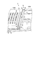
- the top view which showed the back cover of the video display apparatus shown in FIG. The top view shown in the state which removed the 2nd cover of the back cover shown in FIG.
- the top view which expands and shows the surroundings of the 3rd convex part (corresponding to the other 3rd opening part) of the 3rd cover shown in FIG. The top view which expanded and showed the circumference
- the top view which expands and shows the surroundings of the 3rd convex part (corresponding to one 3rd opening part) of the 3rd cover shown in FIG. The top view which expanded and showed the circumference
- surroundings of the 2nd frame and 2nd convex part of the video display apparatus shown in FIG. The perspective view which expanded and showed the overlap part of the video display apparatus shown in FIG. 2, an overlap part, and the step part periphery.
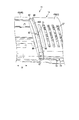
- the perspective view which expanded and showed the 1st cover and 2nd cover periphery of the video display apparatus shown in FIG. FIG. 21 is a cross-sectional view of the first cover and the second cover taken along line F21-F21 shown in FIG.
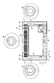
- the video display device (television) of the embodiment is an example of an electronic device and has a substantially rectangular appearance.
- the video display device has a large display panel such as 84 inches.
- the front side (that is, the user side) is the front direction F
- the back side as viewed from the user is the rear direction B
- the left side when viewed from the user is the left direction L
- the right side when viewed from the user is the right direction R
- the upward direction as viewed from the upper side is defined as the upward direction U
- the downward direction as viewed from the user is defined as the downward direction D.
- the video display device 11 has a length of about 2 m in the longitudinal direction W of the display panel 12.
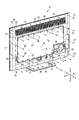
- a video display device 11 includes a flat display panel 12 forming a display screen, and a mask 13 (front bezel) provided in front of the display panel 12 and covering the front thereof.
- a back cover 14 cover that is provided behind the display panel 12 and covers the back of the display panel 12, and a stand 15 (support portion) that supports the display panel 12.
- the display panel 12 is an integrated display unit, and includes a liquid crystal cell, a light source for backlight, a light guide plate that guides light from the light source to the entire liquid crystal cell, and various types of light that diffuse light from the light guide plate.
- An optical sheet and a reflection sheet that reflects the light of the light source irradiated in the rear direction of the light guide plate to the liquid crystal cell side are incorporated.
- the display panel 12 is not limited to a liquid crystal panel, For example, other types of display panels, such as a plasma display panel, organic EL, a plastic display panel, a sheet display panel, may be sufficient.
- the stand 15 is a substantially square, flat plate (frame shape) that is placed on the installation surface, and a pair of rod-like legs 17 that extend from the stand body 16 and support the display panel 12. have.
- the mask 13 is provided in a frame shape (frame shape), and the display panel 12 is exposed to the outside through an opening provided in the center.
- the mask 13 and the back cover 14 constitute a housing 18 of the video display device 11.
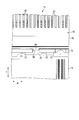
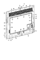
- the video display device 11 includes a first frame 21 (first attachment portion) attached to the rear surface of the display panel 12 and a first frame 21 attached to the rear surface of the display panel 12.
- Two frames 22 second mounting portions
- a plurality of third frames 23 third mounting portions
- a system board 24 circuit board attached to the rear surface of the display panel 12.
- the tuner substrate 25 attached to the rear surface of the display panel 12, the power circuit board 26 attached to the rear surface of the display panel 12, the speaker 27, and the first cover 41 of the back cover 14 are fixed to the display panel 12.
- the fixing member 33 and a.
- Each of the 1st fixing member 31, the 2nd fixing member 32, and the 3rd fixing member 33 is comprised by the screw, for example.
- the system board 24 (circuit board) and the power supply circuit board 26 are provided in a region A between the first frame 21 and the second frame 22, that is, at the center of the rear surface of the display panel 12.
- the first frame 21 (first mounting portion) is a flat metal plate (for example, an iron plate) having a substantially “C” cross section or “ It is formed by bending into a “U” shape.
- the first frame 21 extends in the longitudinal direction W (lateral direction, left-right direction, horizontal direction) of the display panel 12 and has a length smaller than the length in the longitudinal direction W of the display panel 12.
- the first frame 21 is provided near the center of the display panel 12.
- the first frame 21 includes a pair of rectangular first openings 34 provided in the vicinity of both ends thereof, and a plurality (for example, three) of rectangular third openings 36 provided in the vicinity of the center part. ,have.
- the length of one third opening 36 in the longitudinal direction W is larger than the length of the third convex portion 64 of the third cover 43 in the longitudinal direction W (for example, the longitudinal direction W of the third convex portion 64). (About 1.5 to 2 times the length in FIG. 13) (see FIG. 13).
- the length of the other third opening 36 in the longitudinal direction W is substantially the same as the length of the third convex portion 64 in the longitudinal direction W, although there is a slight gap (see FIG. 9). .
- the second frame 22 (second mounting portion) is provided in an elongated flat plate shape by a metal plate (for example, an iron plate).
- the second frame 22 is provided so as to extend in the longitudinal direction W separately from the first frame 21. That is, the second frame 22 is provided in parallel with the first frame 21.
- the second frame 22 has a plurality of (for example, two) square second openings 35.
- the first frame 21 and the second frame 22 not only constitute an attachment part for various components including the back cover 14, but also function as a reinforcing member that prevents the display panel 12 from being bent.
- each of the third frames 23 is provided so as to extend in a direction S (vertical direction, vertical direction, vertical direction) intersecting the longitudinal direction W.
- the third frame 23 includes a total of four pieces.
- the third frame 23 is formed by bending a flat metal plate (for example, an iron plate) into a desired shape.
- the third frame 23 is provided on the rear surface of the display panel 12 and serves not only as a mounting part for various components but also as a reinforcing member for preventing the display panel 12 from being bent.
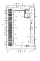
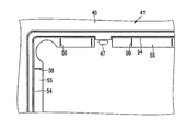
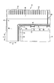
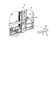
- the back cover 14 includes a plurality of first covers 41 covering positions corresponding to the respective corners (the outer peripheral portion of the display panel 12) on the rear surface of the display panel 12, and the display panel 12.
- a second cover 42 covering the central portion of the rear surface, a third cover 43 provided adjacent to the first protrusion 46 at a position between the first covers 41, and the pair of legs 17 of the stand 15.
- a fourth cover 44 provided at a position between the two (an outer peripheral portion of the display panel 12).
- the fourth cover 44 is formed in a square plate shape by a synthetic resin material, for example.
- the first cover 41 is composed of two pieces. Each of the first covers 41 is integrally formed of, for example, a synthetic resin material so as to form a substantially “C” shape.
- the right first cover 41 and the left first cover 41 shown in FIG. 4 have substantially the same configuration except for a part of the shape.
- Each first cover 41 is attached to the first frame 21 and the second frame 22.
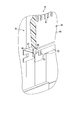
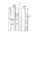
- each of the first covers 41 includes a first body portion 45 extending in a direction S intersecting the longitudinal direction W, and one end portion of the first body portion 45 ( A first protrusion 46 protruding from the upper end) in the longitudinal direction W, and a first protrusion 47 protruding from the first protrusion 46 in the direction approaching the first frame 21 (direction S intersecting the longitudinal direction W) (see FIG. 16), an overlapping portion 48 provided in the first protruding portion 46 and overlapping the overlapping portion of the third cover 43, and a second protrusion protruding in the longitudinal direction W from the other end portion (lower end) of the first main body portion 45.
- a second convex portion 52 see FIG.
- the boundary between the first main body 45 and the first protrusion 46 and the boundary between the first main body 45 and the second protrusion 51 are the inner peripheral portion 81 of the first cover 41.
- the first protrusion 46 and the second protrusion 51 protrudes in the longitudinal direction W from a line extending the inner peripheral portion 81 in the direction S intersecting the longitudinal direction W.
- the first main body 45 is provided at a position away from the first frame 21.
- the first convex portion 47 can be fitted into the first opening 34.
- the second convex portion 52 can be fitted into the second opening 35.
- the first protrusion 46 and the second protrusion 51 are provided outside the region A.
- each of the first covers 41 includes a plurality of first holes 53 through which the first fixing member 31 passes, and a second cover 42 provided in the inner peripheral portion of the first cover 41.
- the first support portion 55 is provided on the inner side of the first groove portion 54 to support the second cover 42, and the second cover is provided so as to protrude from the first support portion 55.
- a plurality of first small pieces 56 (see FIG. 16) abutted against 42.
- the 1st hole 53 provided in the 1st main-body part 45 is formed in the ellipse long in the direction S which cross
- the 1st hole 53 provided in the 1st protrusion part 46 is formed in the ellipse long in the longitudinal direction W (refer FIG. 4).
- the first hole 53 provided in the first protrusion 46 is provided as close as possible to the third cover 43, and the first hole 53 and the first fixing member that passes through the first hole 53.
- the third cover 43 is prevented from being lifted by 31 (a lift preventing structure).
- the first protrusion 46 is provided with a plurality of vent holes 57 for discharging the air heated inside the housing 18 to the outside.
- a plurality of reinforcing ribs 74 are provided on the inner surface of the first protrusion 46.
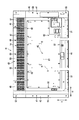
- the second cover 42 is provided in a substantially flat plate shape by a metal material such as iron.
- a bent portion 58 is provided that is bent in a circular cross section so as to be fitted into a groove portion provided in the first cover 41 and the third cover 43.
- the second cover 42 has a second main body portion 61 and a plurality of second holes 62 provided in the second main body portion 61 and through which the second fixing member 32 can pass.
- the second cover 42 covers the area A between the first frame 21 and the second frame 22.
- the second cover 42 electromagnetically blocks the area A between the first frame 21 and the second frame 22, and electromagnetic waves radiated from the system board 24, the power circuit board 26, etc. in the area A are received. Preventing leakage to the outside. For this reason, the second cover 42 functions as an electromagnetic wave shield covering the region A. That is, the metal case of the display panel 12, the second cover 42, the first frame 21, the second frame 22, and the third frame 23 constitute a shield case that prevents leakage of electromagnetic waves, and the region A is Surrounded by this shield case.
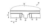
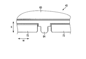
- the third cover 43 is formed in a substantially rectangular plate shape by, for example, a synthetic resin material.
- the third cover 43 is attached to the first frame 21.
- the third cover 43 is disposed outside the region A.
- the third cover 43 has, for example, an arc shape that protrudes rearward.
- the third cover 43 approaches the first frame 21 from the third main body 63 extending in the longitudinal direction W and the third main body 63.
- a third convex portion 64 (convex portion) projecting in the direction (direction S intersecting the longitudinal direction W) (see FIGS. 9 and 13).
- the third protrusion 64 can be fitted into the third opening 36.
- the third convex portion 64 can be fitted into the third opening 36.
- the third convex portion 64 can slide along the longitudinal direction W before and after thermal expansion of the third cover 43 in one third opening portion 36 (see FIG. 13).
- the third cover 43 approaches the first cover 41 from the step portion 65 provided at a position adjacent to the first cover 41 of the third main body portion 63.
- An overlapping margin portion 66 protruding in the direction, a plurality of rail portions 67 provided on the overlapping margin portion 66 and protruding toward the overlapping portion 48, a plurality of third holes 68 for passing the third fixing member 33,
- a third groove portion 71 provided on the inner peripheral portion of the first cover 41 to which the second cover 42 is attached; a third support portion 72 provided on the inner side of the third groove portion 71 to support the second cover 42;
- a plurality of third small pieces 73 provided so as to protrude from the three support portions 72 and abutted against the second cover 42.
- the third main body 63 is provided with a plurality of vent holes 57 for discharging the air heated inside the housing 18 to the outside.
- the third cover 43 is in contact with the overlapping portion 48 of the first cover 41 via each rail portion 67.
- the third hole 68 is formed in an oval shape that is long in the longitudinal direction W.
- a plurality of reinforcing ribs 74 formed thinner than the third main body 63 of the third cover 43 are provided on the inner surface side of the third cover 43. It should be noted that both ends of the third cover 43 are lifted by the difference in the curing speed of the resin after molding (the thin reinforcing rib 74 is cured first and the thick third main body 63 is delayed and cured). Tend to be warped. For this reason, the above-described lifting prevention structure functions effectively.
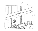
- a gap 75 is provided between the overlapping portion 48 of the first cover 41 and the step portion 65 of the third cover 43.
- the end surface 48A of the overlapping portion 48 is at a position indicated by a solid line in FIG. 19, and the gap 75 between the end surface of the overlapping portion 48 and the step portion 65 is set to 1.5 mm, for example.
- the video display device 11 is operated and the first cover 41 and the third cover 43 are expanded by heat in the longitudinal direction W, as shown by a two-dot chain line in FIG. Is brought into contact with the stepped portion 65.
- the assembly process of the video display device 11 of this embodiment will be described.
- the video display device 11 of the present embodiment is assembled with the display panel 12 standing up. That is, the stand 15 is attached to the display panel 12, and the display panel 12 is self-supporting.
- a mask 13 is fixed to the front surface of the display panel 12 by a predetermined means.
- a first frame 21, a second frame 22, and a third frame 23 are attached to the rear surface of the display panel 12 in advance.
- the system board 24, the tuner board 25, and the power circuit board 26 are attached to the rear surface of the display panel 12 by fixing means such as screws.
- the system board 24 and the power supply circuit board 26 are fixed in a region A between the first frame 21 and the second frame 22.
- the tuner substrate 25 is previously provided with a shield structure for preventing leakage of electromagnetic waves.
- the third convex portion 64 of the third cover 43 is inserted into the third opening 36 of the first frame 21 to temporarily fix the third cover 43 to the first frame 21 (FIG. 9).
- the first protrusion 47 of the first cover 41 is inserted into the first opening 34 of the first frame 21, and the first protrusion 46 of the first cover 41 is temporarily fixed to the first frame 21.
- the first cover 41 tries to rotate around the first convex portion 47, so that the second convex portion 52 of the first cover 41 is inserted into the second opening 35 of the second frame 22. (See FIG. 17).
- the first cover 41 is held at two locations, upper and lower (both ends), the first cover 41 is temporarily fixed to the first frame 21 and the second frame 22 without rotating.
- the first cover 41 is fixed to the display panel 12 by the first fixing member 31, and the third cover 43 is fixed to the display panel 12 by the second fixing member 32.
- the fourth cover 44 is fixed to the display panel 12 by fixing means such as screws.
- the bent portion 58 of the second cover 42 is inserted into the first groove portion 54 of the first cover 41, the third groove portion 71 of the third cover 43, and the groove portion of the fourth cover 44, and the first cover 41,
- the second cover 42 is temporarily fixed to the third cover 43 and the fourth cover 44.
- the second cover 42 is fixed to the display panel 12 by the second fixing member 32, and the video display device 11 is completed.
- the region A is in a state in which leakage of electromagnetic waves is prevented by the second cover 42.
- the video display device 11 is provided on the rear surface of the display panel 12 and the display panel 12 so as to extend in the longitudinal direction W of the display panel 12, and the first opening 34 is provided.
- An attachment portion and a first cover 41 attached to the first attachment portion and covering a part of the rear surface of the display panel 12.
- the first cover 41 is longitudinally located at a position away from the first attachment portion.
- a first main body 45 provided so as to extend in a direction intersecting W, a first protrusion 46 protruding from the first main body 45 in the longitudinal direction W, and a first opening while protruding from the first protrusion 46
- a first protrusion 47 that fits into the portion 34.
- the first main body portion 45 extends in the direction S intersecting the longitudinal direction W at a position deviated from the first attachment portion, the first convex portion 47 and the first opening portion 34 are The first cover 41 can be temporarily fixed to the first mounting portion using the first convex portion 47, and workability can be improved.
- the video display device 11 includes a second mounting portion that is provided on the rear surface of the display panel 12 so as to extend in the longitudinal direction W at a position separated from the first mounting portion, and has a second opening 35.
- the first cover 41 includes a second protrusion 51 that protrudes from the first main body 45 in the longitudinal direction W, and a second protrusion 52 that protrudes from the second protrusion 51 and fits into the second opening 35.
- the first cover 41 when the first cover 41 is temporarily fixed to the first mounting portion using the first convex portion 47, the first cover 41 rotates around the first convex portion 47. Can be prevented. For this reason, the 1st cover 41 can be stabilized in the case of the said temporary fix
- the video display device 11 includes a circuit board provided in a region A between the first mounting portion and the second mounting portion on the rear surface of the display panel 12, and a metal second cover 42 covering the region A. , With. According to this configuration, an electromagnetic wave shield can be formed by the second cover 42, and electromagnetic waves generated from the circuit board can be prevented from leaking out to the surroundings.
- the first cover 41 is made of resin, and the first protrusion 46 and the second protrusion 51 are provided outside the region A. According to this configuration, the first cover 41 made of resin can be disposed in a so-called outer peripheral region on the back surface. As a result, a fine shape (the vent hole 57, the reinforcing rib 74, the first convex portion 47, etc.) can be formed with the resin, and the first cover 41 with the fine shape is formed on the display panel 12. It can arrange
- the video display device 11 includes a resin-made third cover 43 provided adjacent to the first protrusion 46 so as to extend in the longitudinal direction W outside the region A, and includes the first protrusion 46 and the third cover.
- a gap 75 is provided between the gaps 43 and 43.
- one of the first protrusion 46 and the third cover 43 has a step portion 65 and an overlapping margin portion 66 protruding from the step portion 65.
- the other of the three covers 43 has an overlapping portion 48 that overlaps the overlapping margin portion 66, and a gap 75 is provided between the step portion 65 and the overlapping portion 48. According to this configuration, since the gap 75 is provided at the position where the overlap margin portion 66 is covered, the internal structure of the video display device 11 is not seen at the position of the gap 75, and the appearance can be improved.
- the overlapping margin portion 66 is provided with a plurality of rail portions 67 protruding so as to contact the overlapping portion 48. According to this configuration, the frictional force generated between the overlapping margin portion 66 and the overlapping portion 48 during thermal expansion can be reduced, and the thermal expansion of the first cover 41 and the third cover 43 can be made smooth. Further, since each rail portion 67 can be brought into contact with a point, the strictness of the forming accuracy of the overlapping portion 48 (particularly, the inner surface thereof) can be relaxed and the cost can be reduced.
- the first cover 41 has a plurality of small pieces abutted against the second cover 42.
- the third cover 43 has a plurality of small pieces that abut against the second cover 42. According to these configurations, the second cover 42 can be brought into contact with the first cover 41 and the third cover 43 at points. Accordingly, it is possible to prevent the vibration of the first cover 41 and the third cover 43 generated by the speaker 27 and the like from being transmitted to the second cover 42 side and continuously generating vibration in the second cover 42.
- the video display device 11 includes a first fixing member 31 for fixing the first cover 41 to the display panel 12, and the first main body 45 has a first hole that is elongated in a direction intersecting the longitudinal direction W. 53 is provided, and the first fixing member 31 is passed through the first hole 53.
- the video display device 11 includes a third fixing member 33 for fixing the third cover 43 to the display panel 12.
- the third cover 43 has a third hole 68 that is elongated in the longitudinal direction W.
- the third fixing member 33 is passed through the third hole 68.
- the first cover 41 can be prevented from cracking when the first cover 41 is thermally expanded while the video display device 11 is in operation.
- the video display device 11 includes a third opening 36 provided in the first attachment portion, and the third cover 43 protrudes from the third main body 63 and the third main body 63 and the third opening 36. And the length of the third opening 36 in the longitudinal direction W is greater than the length of the third projection 64 in the longitudinal direction W. The inside of the third opening 36 can be moved before and after thermal expansion of the 3 cover 43.
- the third protrusion 64 can be allowed to move when the third cover 43 is thermally expanded, and the third cover 43 can be prevented from being lifted or deformed.
- the video display device 11 is attached to the display panel 12 provided with an attachment portion, the first cover 41 made of resin that is attached to the attachment portion and covers the outer peripheral portion of the rear surface of the display panel 12, and the attachment portion.
- the metal 2nd cover 42 which covered the center part of the rear surface of the display panel 12 and the circuit board provided in the center part of the rear surface of the display panel 12 are provided.
- an electromagnetic wave shield can be configured by the metal second cover 42, and electromagnetic waves generated from the circuit board can be prevented from leaking to the outside.
- the first cover 41 made of resin can be disposed on the outer peripheral side, and a fine shape (such as the vent hole 57, the reinforcing rib 74, and various convex portions) can be formed by the resin. Thereby, the functionality of the first cover 41 can be improved.
- the video display device 11 includes a display panel 12 provided with an attachment portion, a resin first cover 41 attached to the attachment portion and covering the rear surface of the display panel 12, and attached to the attachment portion. 12, a resin-made third cover 43 covering the rear surface, and one of the first cover 41 and the third cover 43 includes a step portion 65, an overlapping margin portion 66 extending from the step portion 65, and The other of the first cover 41 and the third cover 43 has an overlapping portion 48 that overlaps the overlapping margin portion 66, and a gap 75 is provided between the step portion 65 and the overlapping portion 48. .
- the first cover 41 and the third cover 43 are thermally expanded, it is possible to prevent the first cover 41 and the third cover 43 from abutting and deforming so as to rise. Further, since the gap 75 is provided at the position where the overlap margin 66 is covered, the internal structure of the video display device 11 is not seen at the position of the gap 75, and the appearance can be improved.
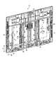
- the video display device 11 which is an example of the electronic device of the second embodiment, is the first implementation in that the third cover 43 and the fourth cover 44 are not provided and the leg portion 17 of the stand 15 is composed of one piece. Although different from the one in the form, other parts are common to the first embodiment. For this reason, a different part from 1st Embodiment is mainly demonstrated, and illustration or description is abbreviate
- the video display device 11 of the second embodiment is a smaller model than the first embodiment, and has a display panel 12 of about 65 inches, for example.
- the first cover 41 is composed of two pieces. Each of the first covers 41 is integrally formed of a synthetic resin material so as to form a substantially “C” shape.
- Each of the first covers 41 includes a first main body 45 extending in a direction S intersecting the longitudinal direction, and a first protrusion 46 projecting in the longitudinal direction W from one end (upper end) of the first main body 45.
- the first protrusion 47 protruding from the first protrusion 46 in the direction approaching the first frame 21 (direction S intersecting the longitudinal direction W), and the other end (lower end) of the first main body 45. It has the 2nd protrusion part 51 which protruded in the direction W, and the 2nd convex part 52 which protruded in the direction (front direction) which approaches the 2nd frame 22 from the 2nd protrusion part 51.
- Each of the first covers 41 includes a plurality of first holes 53 for allowing the first fixing member 31 to pass therethrough, a first groove portion 54 provided on the inner peripheral portion of the first cover 41 to which the second cover 42 is attached, A first support portion 55 provided inside the one groove portion 54 to support the second cover 42, and a plurality of first small pieces provided to protrude from the first support portion 55 and in contact with the second cover 42 56.
- the first protruding portion 46 of one first cover 41 is provided with an overlapping portion 48 that overlaps the overlapping margin 66 of the other first cover 41.
- the first protruding portion 46 of the other first cover 41 protrudes in a direction approaching the first cover 41 from the step portion 65 provided at a position adjacent to the first cover 41.
- An overlapping margin portion 66 and a plurality of rail portions 67 provided on the overlapping margin portion 66 and projecting toward the overlapping portion 48 are provided.
- a gap 75 is provided between the overlapping portion 48 and the stepped portion 65, and the conditions such as the dimension of the gap 75 are the same as those in the first embodiment.
- the first cover 41 can be temporarily fixed to the first mounting portion, and workability can be improved. Further, when the two first covers 41 are thermally expanded, the first covers 41 can be prevented from colliding with each other and deforming so as to rise.
- the video display device 11 which is an example of the electronic device of the second embodiment, is first in that a step portion 65 and an overlap margin portion 66 are provided in the first cover 41, and an overlap portion 48 is provided in the third cover 43. It differs from that of the embodiment. However, other parts are common to the first embodiment.
- a gap 75 is provided between the overlapping portion 48 of the first cover 41 and the step portion 65 of the third cover 43. Conditions such as the size of the gap 75 are the same as those in the first embodiment.
- the same effect as the first embodiment is obtained. It can be demonstrated.
- the video display device 11 is not limited to the above-described embodiment as it is, and can be embodied by modifying the constituent elements without departing from the scope of the invention in the implementation stage.
- various inventions can be formed by appropriately combining a plurality of constituent elements disclosed in the embodiment. For example, some components may be deleted from all the components shown in the embodiment. Furthermore, you may combine the component covering different embodiment suitably.
Landscapes
- Engineering & Computer Science (AREA)
- Multimedia (AREA)
- Signal Processing (AREA)
- Devices For Indicating Variable Information By Combining Individual Elements (AREA)
Priority Applications (1)
| Application Number | Priority Date | Filing Date | Title |
|---|---|---|---|
| US14/012,643 US20140185252A1 (en) | 2012-12-27 | 2013-08-28 | Image display device |
Applications Claiming Priority (2)
| Application Number | Priority Date | Filing Date | Title |
|---|---|---|---|
| JP2012286150A JP6184692B2 (ja) | 2012-12-27 | 2012-12-27 | 映像表示装置 |
| JP2012-286150 | 2012-12-27 |
Related Child Applications (1)
| Application Number | Title | Priority Date | Filing Date |
|---|---|---|---|
| US14/012,643 Continuation US20140185252A1 (en) | 2012-12-27 | 2013-08-28 | Image display device |
Publications (1)
| Publication Number | Publication Date |
|---|---|
| WO2014103382A1 true WO2014103382A1 (ja) | 2014-07-03 |
Family
ID=51020491
Family Applications (1)
| Application Number | Title | Priority Date | Filing Date |
|---|---|---|---|
| PCT/JP2013/058624 Ceased WO2014103382A1 (ja) | 2012-12-27 | 2013-03-25 | 映像表示装置 |
Country Status (2)
| Country | Link |
|---|---|
| JP (1) | JP6184692B2 (enExample) |
| WO (1) | WO2014103382A1 (enExample) |
Citations (3)
| Publication number | Priority date | Publication date | Assignee | Title |
|---|---|---|---|---|
| JP2006201318A (ja) * | 2005-01-19 | 2006-08-03 | Sharp Corp | シャーシ構造 |
| JP2008003247A (ja) * | 2006-06-21 | 2008-01-10 | Sony Corp | 枠組み装置及び平面型表示装置 |
| JP2010282493A (ja) * | 2009-06-05 | 2010-12-16 | Toshiba Corp | 電子機器 |
Family Cites Families (1)
| Publication number | Priority date | Publication date | Assignee | Title |
|---|---|---|---|---|
| JP2009058915A (ja) * | 2007-09-04 | 2009-03-19 | Toshiba Corp | 液晶表示装置 |
-
2012
- 2012-12-27 JP JP2012286150A patent/JP6184692B2/ja active Active
-
2013
- 2013-03-25 WO PCT/JP2013/058624 patent/WO2014103382A1/ja not_active Ceased
Patent Citations (3)
| Publication number | Priority date | Publication date | Assignee | Title |
|---|---|---|---|---|
| JP2006201318A (ja) * | 2005-01-19 | 2006-08-03 | Sharp Corp | シャーシ構造 |
| JP2008003247A (ja) * | 2006-06-21 | 2008-01-10 | Sony Corp | 枠組み装置及び平面型表示装置 |
| JP2010282493A (ja) * | 2009-06-05 | 2010-12-16 | Toshiba Corp | 電子機器 |
Also Published As
| Publication number | Publication date |
|---|---|
| JP2014128010A (ja) | 2014-07-07 |
| JP6184692B2 (ja) | 2017-08-23 |
Similar Documents
| Publication | Publication Date | Title |
|---|---|---|
| EP3764154B1 (en) | Display apparatus | |
| JP4945667B2 (ja) | 表示装置 | |
| JP5468692B1 (ja) | 液晶表示装置 | |
| EP3200019B1 (en) | Backlight module and display device | |
| JP2012151380A (ja) | 表示装置および電子機器 | |
| KR20090057519A (ko) | 디스플레이 장치 | |
| US20140177147A1 (en) | Display device and method of manufacturing the same | |
| CN106814487B (zh) | 显示装置 | |
| US9250377B2 (en) | Light guide plate and backlight module and display module using the same | |
| US10114169B2 (en) | Display device | |
| WO2019134382A1 (zh) | 背光模组及显示装置 | |
| JP6184692B2 (ja) | 映像表示装置 | |
| KR101866394B1 (ko) | 평판형 영상 표시장치 및 그 조립방법 | |
| JP5865887B2 (ja) | 表示装置 | |
| EP2821819B1 (en) | Reflectors for the corners of a direct backlight in a display device | |
| US20140185252A1 (en) | Image display device | |
| JP3179072U (ja) | 表示パネルアッセンブリまたは該表示パネルアッセンブリを有する表示装置 | |
| CN102831824A (zh) | 显示器和电子单元 | |
| JP6173710B2 (ja) | 電子機器 | |
| KR102658217B1 (ko) | 백라이트 유닛 및 이를 포함하는 액정표시장치 | |
| JP2017005349A (ja) | 表示装置およびテレビジョン受信機 | |
| JP2014089424A (ja) | 映像表示装置および電子機器 | |
| JP2015125180A (ja) | 表示装置 | |
| JP5416851B2 (ja) | 液晶表示装置及び液晶テレビ | |
| JP5651735B2 (ja) | 表示装置およびテレビジョン受像機 |
Legal Events
| Date | Code | Title | Description |
|---|---|---|---|
| 121 | Ep: the epo has been informed by wipo that ep was designated in this application |
Ref document number: 13867970 Country of ref document: EP Kind code of ref document: A1 |
|
| NENP | Non-entry into the national phase |
Ref country code: DE |
|
| 122 | Ep: pct application non-entry in european phase |
Ref document number: 13867970 Country of ref document: EP Kind code of ref document: A1 |