WO2014102871A1 - 血圧計 - Google Patents
血圧計 Download PDFInfo
- Publication number
- WO2014102871A1 WO2014102871A1 PCT/JP2012/008385 JP2012008385W WO2014102871A1 WO 2014102871 A1 WO2014102871 A1 WO 2014102871A1 JP 2012008385 W JP2012008385 W JP 2012008385W WO 2014102871 A1 WO2014102871 A1 WO 2014102871A1
- Authority
- WO
- WIPO (PCT)
- Prior art keywords
- air bag
- upper arm
- air
- armband
- ischemia
- Prior art date
- Legal status (The legal status is an assumption and is not a legal conclusion. Google has not performed a legal analysis and makes no representation as to the accuracy of the status listed.)
- Ceased
Links
Images







Classifications
-
- A—HUMAN NECESSITIES
- A61—MEDICAL OR VETERINARY SCIENCE; HYGIENE
- A61B—DIAGNOSIS; SURGERY; IDENTIFICATION
- A61B5/00—Measuring for diagnostic purposes; Identification of persons
- A61B5/02—Detecting, measuring or recording for evaluating the cardiovascular system, e.g. pulse, heart rate, blood pressure or blood flow
- A61B5/021—Measuring pressure in heart or blood vessels
- A61B5/022—Measuring pressure in heart or blood vessels by applying pressure to close blood vessels, e.g. against the skin; Ophthalmodynamometers
-
- A—HUMAN NECESSITIES
- A61—MEDICAL OR VETERINARY SCIENCE; HYGIENE
- A61B—DIAGNOSIS; SURGERY; IDENTIFICATION
- A61B5/00—Measuring for diagnostic purposes; Identification of persons
- A61B5/02—Detecting, measuring or recording for evaluating the cardiovascular system, e.g. pulse, heart rate, blood pressure or blood flow
- A61B5/024—Measuring pulse rate or heart rate
- A61B5/02438—Measuring pulse rate or heart rate with portable devices, e.g. worn by the patient
-
- A—HUMAN NECESSITIES
- A61—MEDICAL OR VETERINARY SCIENCE; HYGIENE
- A61B—DIAGNOSIS; SURGERY; IDENTIFICATION
- A61B5/00—Measuring for diagnostic purposes; Identification of persons
- A61B5/74—Details of notification to user or communication with user or patient; User input means
- A61B5/742—Details of notification to user or communication with user or patient; User input means using visual displays
Definitions
- the present invention relates to a sphygmomanometer that measures the blood pressure of a patient by wrapping an armband portion.
- Blood pressure monitors used by medical personnel such as nurses at medical institutions include a manual pressurization type in which an air balloon for supplying air to the armband and a blood pressure monitor main body are integrated.
- the arm band portion of the blood pressure monitor has an ischemic air bag for blocking the artery and an arterial pulsation detecting air bag attached to the ischemic air bag.
- a medical worker manually holds or releases the air balloon, air is sent from the sphygmomanometer body through the tube to the air bag for ischemia in the armband, and the patient's upper arm is pressurized to measure blood pressure.
- Medical personnel can easily operate the air balloon with one hand, and when sending air to the air bag for ischemia in the armband, a motor to send air is unnecessary, so quiet blood pressure measurement should be performed even at night (See Patent Document 1).
- the blood pressure measurement is performed by wrapping the arm band part of the conventional blood pressure monitor around the upper arm of the patient (the person to be measured), if the upper arm is pressurized by putting air into the air bag for ischemia (large bag), the arm band The inner surface of the part moves and a bent part is generated at a place where the arm band part is located. Deep wrinkles occur at the bent portion of the inner surface of the armband. When deep wrinkles are generated on the inner surface side of the arm band part, a part of the upper arm skin may be pulled together with the inner surface of the arm band part, and a part of the upper arm skin may be drawn into the deep wrinkle.
- an object of the present invention is to provide a sphygmomanometer that can prevent the occurrence of internal hemorrhage without causing the patient to feel uncomfortable when the blood pressure measurement is performed with the arm band part attached to the upper arm of the patient.
- the sphygmomanometer according to the present invention is a sphygmomanometer that has an arm band part and measures the blood pressure by winding the arm band part around the upper arm of a person to be measured and pressurizing the arm band part, and the arm band part supplies air
- a body member having an air bag for ischemia for blocking the upper arm, and the pulsation of the artery of the upper arm is detected by supplying the air.
- An air bag for detecting arterial pulsation, and the body member has the upper arm skin drawn into wrinkles formed on the inner surface of the arm band when the arm band pressurizes the upper arm.
- a pull-in preventing member for preventing the above is arranged.
- the main body member is provided with the pull-in preventing member for preventing the upper arm skin from being drawn into the wrinkles generated on the inner surface of the arm band portion when the upper arm is pressed by the arm band portion. Therefore, the frictional force between the inner surface of the armband portion and the skin of the upper arm can be reduced. For this reason, even if the inner surface of the arm band moves when the upper arm is pressurized, it is possible to reduce the movement of the upper arm skin together. Therefore, even if deep wrinkles are formed on the inner surface of the armband part, there is no possibility that a part of the upper arm skin is drawn into the deep wrinkles, so the armband part is attached to the upper arm of the patient to measure blood pressure. In this case, internal bleeding can be prevented without causing the patient to feel uncomfortable.
- the pull-in preventing member is arranged on the air bag for ischemia and the air bag for detecting arterial pulsation of the main body member.
- the pull-in preventing member is disposed on the air bag for ischemia of the main body member that touches the skin of the upper arm and the air bag for detecting arterial pulsation. Can be prevented from being drawn into.
- the main body member has a first surface portion and a second surface portion overlapping the first surface portion, and the second surface portion contacting the skin of the upper arm uses a fusion portion to form the air bag for ischemia.
- the pull-in preventing member is fixed to the fused portion by stitching or fusing with a thread. According to the above configuration, since the pull-in preventing member is fixed to the fused portion by stitching or fusing with a thread, the pull-in preventing member can be reliably fixed to the main body member.
- the main body member has a first surface portion and a second surface portion overlapping the first surface portion, and the second surface portion contacting the skin of the upper arm uses a fusion portion to form the air bag for ischemia.
- the pull-in preventing member is detachably fixed to the fused portion. According to the above configuration, since the pull-in preventing member is detachably fixed to the fused portion, the pull-in preventing member can be securely fixed to the main body member, and the used pull-in preventing member can be newly pulled in. Since it can be easily replaced with a prevention member, it is hygienic.
- the medical worker has a blood pressure monitor main body part connected to the air bag for ischemia of the armband part and the air bag for arterial pulsation detection using a tube, and the blood pressure monitor main body part is a housing And an air supply balloon that is attached to the housing and pushes the air through the tube to send the air to the air bag for ischemia and the air bag for detecting arterial pulsation.
- the medical worker can wrap the armband portion around the upper arm while easily positioning the armband with the other hand while the medical worker holds the air balloon with one hand.
- the present invention can provide a sphygmomanometer that can prevent the occurrence of internal hemorrhage without causing the patient to feel uncomfortable when the blood pressure measurement is performed with the arm band part attached to the upper arm of the patient.
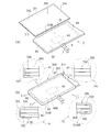
- FIG. 1 is a perspective view showing a first preferred embodiment of a sphygmomanometer according to the present invention.
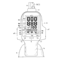
- the front view of the sphygmomanometer shown in FIG. The figure which shows the example of the display item which the display part of a blood pressure meter main-body part can display.
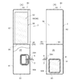
- FIG. 7A is a perspective view showing the inner surface side of the armband portion 3
- FIG. 7B is a perspective view showing the outer surface side of the armband portion 3.
- FIG. 7A is a perspective view showing the inner surface side of the armband portion 3
- FIG. 7B is a perspective view showing the outer surface side of the armband portion 3.
- FIG. 7C is a cross-sectional view taken along line AA of the armband portion shown in FIG.
- Sectional drawing in the BB line which shows the vicinity of the air bag for arterial pulsation detection and the air bag for ischemia of FIG. 7 (A).
- the perspective view which shows the inner surface side of the arm band part to which the drawing-in prevention member was attached.
- the perspective view which shows the outer surface side of the arm band part to which the drawing-in prevention member was attached.
- FIG. 16A shows a state near the skin of the upper arm T at the time of blood pressure measurement by the arm band portion having the pull-in preventing member in the first embodiment of the present invention
- FIG. 16B shows the arm band of the comparative example.
- FIG. 1 is a perspective view showing a preferred first embodiment of a sphygmomanometer according to the present invention.
- FIG. 2 is a front view of the sphygmomanometer shown in FIG.
- the sphygmomanometer 1 is a person to be measured by pressurizing an air bag in an arm band attached to a patient's upper arm T by a manual pressurization method by a medical staff such as a nurse. The patient's blood pressure can be measured.
- This manual pressurization type sphygmomanometer 1 has an air balloon (pressurization unit) and a sphygmomanometer main body integrated, and a medical worker can pressurize the air balloon with one hand, Therefore, it is possible to measure blood pressure quietly even at night.
- the medical staff can select three measurement modes according to the patient's pathological condition.
- the three measurement modes are a normal mode, a slow mode, and an auscultation mode.
- the normal mode is a mode in which blood pressure measurement can be performed more quickly by automatic measurement.
- Slow mode is a mode in which the pressure reduction rate after pressurization can be set slower than the pressure reduction rate after pressurization in normal mode, and blood pressure can be measured for patients with low blood pressure or patients with weak pulses. It is.
- the auscultation mode is a mode in which a medical worker measures blood pressure by an auscultation method using a stethoscope without performing automatic measurement.
- the measurement method in the sphygmomanometer 1 shown in FIGS. 1 and 2 is an oscillometric method (a so-called double cuff method using an air bag for ischemia and an air bag for detecting arterial pulsation).
- FIG. I the upper arm T of the patient who is the subject.
- a power source to be used for example, a dry battery is used.
- the sphygmomanometer 1 has a sphygmomanometer main body 2 and an armband 3.
- the sphygmomanometer main body 2 includes a housing 4 and an air balloon 5.
- the air balloon 5 is a pressurizing unit that can send air inside by a medical worker performing a pressurizing operation, and is made of a stretchable material.
- the air balloon 5 is a rubber balloon, for example.
- a pull-in preventing member made of a slippery material is disposed on the inner surface side of the arm band portion 3. .
- a part of the skin of the upper arm T is not pulled by the deep wrinkles generated on the inner surface side of the arm band portion 3, so that the patient does not feel uncomfortable when pressurizing with the arm band portion 3 to measure blood pressure. It has a function that can improve the wearing feeling of the armband part 3 and prevent the occurrence of internal bleeding.
- the housing 4 of the sphygmomanometer main body 2 shown in FIG. 1 and FIG. 2 is made of plastic, and has a rectangular display portion 8, a power switch 9, a mode switch 10, and an exhaust switch 11.
- the display unit 8 is, for example, a liquid crystal display device or an organic EL (electroluminescence) display device, and may be a single color display or a color display.
- the display unit 8 can display a maximum blood pressure value, a minimum blood pressure value, a pulse rate, and which of the three measurement modes described above is selected.
- the power switch 9 shown in FIG. 1 and FIG. 2 can be turned on or off by the medical staff when pressed.
- the mode switch 10 can switch the measurement mode to any of the above-described normal mode, slow mode, and auscultation mode.
- the exhaust switch 11 can be forcibly exhausted by a medical worker when the air in the air bag for ischemia in the armband portion 3 and air in the air bag for detecting arterial pulsation, which will be described later, is pressed. it can.
- the two tubes 6 and 7 shown in FIG. 1 are flexible tubes that connect the housing 4 of the blood pressure monitor main body 2 and the armband 3.
- the tube 6 is thicker than the tube 7.
- One end portion 6 ⁇ / b> B of the tube 6 is connected to the upper portion of the housing 4 via the connector portion 12.
- One end portion 7B of the tube 7 is connected to the upper portion of the housing 4 via a plug 7C and a connector portion 12.
- the vicinity of the ends 6B and 7B of the tubes 6 and 7 are fixed by a holder 13.
- the tubes 6 and 7 are fixed by the holder 13 so that the tubes 6 and 7 are not separated, but the one end portion 7B of the thin tube 7 is connected to the one end portion 6B of the thick tube 6.
- the length of the tube 7 has a margin so that the movement of the tube 7 can follow the movement of the tube 6.
- an extension portion 14 is formed projecting downward from the lower portion of the housing 4.
- the extension portion 14 is a thin plate-like member that covers a part of the front portion 5S of the air balloon 5.
- the medical staff repeats the operation of grasping and releasing the air balloon 5 while supporting the extension 14 with the fingers of the hand H, whereby the air from the air balloon 5 is converted into the blood pressure monitor main body 2. It can be supplied to the air bag for ischemia and the air bag for detecting arterial pulsation in the armband portion 3 through the inner pipe and the tubes 6 and 7. Projections 4T are formed on both sides of the housing 4.
- the display unit 8 includes a maximum blood pressure value display area 8A, a minimum blood pressure value display area 8B, a pulse display area 8C, a pulse wave signal display area 8D, a previous value display area 8E, and a display area during exhaust. 8F, under-pressurized display area 8G, over-pressurized display area 8H, and selected mode display area 8K.
- the systolic blood pressure value display area 8A shown in FIG. 3 displays the instantaneous blood pressure during pressurization and decompression, and finally displays the systolic blood pressure value.
- the lowest blood pressure value display area 8B displays the lowest blood pressure value finally determined.
- the pulse display area 8C shown in FIG. 3 displays the measured pulse value.
- the pulse wave signal display area 8D displays the magnitude of the detected pulse wave signal, and the magnitude of the pulse wave signal is displayed in a bar shape that moves to the left and right.
- the display of the magnitude of the pulse wave signal rhythmically increases or decreases from side to side, but in the case of a patient with arrhythmia, the display of the magnitude of the pulse wave signal Rhythmically does not increase or decrease from side to side.
- the previous value display area 8E shown in FIG. 3 blinks or lights up when the power switch 9 is pressed to activate the operation of the sphygmomanometer body 2, and the highest blood pressure value, lowest blood pressure value, and pulse value measured last time are the highest. It is displayed in the hypertension value display area 8A, the minimum blood pressure value display area 8B, and the pulse display area 8C. Then, after a while or when the air balloon 5 is operated to supply air, the display of the highest blood pressure value, the lowest blood pressure value, and the pulse value measured last time disappears, and the display area 8E for the previous value is displayed. When the power switch 9 is pressed and the operation of the sphygmomanometer body 2 is started, the blinking or lighting is also extinguished.
- the display area 8 ⁇ / b> F during exhausting blinks when the air in the air bag for ischemia and the air bag for detecting arterial pulsation in the armband 3 is rapidly exhausted.
- the display area 8F during exhaust also blinks when the exhaust switch 11 is pressed.
- the underpressurized display area 8G shown in FIG. 3 When the underpressurized display area 8G shown in FIG. 3 is lit or blinking, it indicates that the pressure in the armband 3 has not reached a level sufficient for blood pressure measurement. Can be further encouraged to send air using the air balloon 5.
- the overpressurization display area 8H When the overpressurization display area 8H is lit or flashing, it indicates that the pressure in the armband 3 is equal to or higher than a predetermined pressure (for example, 320 mmHg or higher), and the medical worker overpressurizes. By confirming the display area 8H, it is possible to prompt the user to stop the pressurizing operation.
- the mode display area 8K being selected shown in FIG. 3 displays which mode is selected from the normal mode, the slow mode, and the auscultation mode when the mode switch 10 is pressed. By selecting this mode, the exhaust (decompression) speed can be changed.
- the exhaust speed is set to about 5 mmHg / sec, for example. In the normal mode, there is an advantage that the measurement time can be made relatively short because the exhaust speed is relatively fast.
- the increment of the pressure change measurement is large, there is no particular problem when measuring a person with stable pulse, but when measuring the blood pressure of a person with arrhythmia, the pulse is easily lost. Measurement error may increase.
- a slow mode is provided, and when this slow mode is selected, the exhaust speed is set to approximately half of the normal mode, for example, 2.0 to 2.5 mmHg / sec.
- the auscultation mode is a mode in which measurement is performed manually using a stethoscope.
- the exhaust speed is set to about half of the normal mode, for example, 2.0 to 3.0 mmHg / sec.
- FIG. 4 shows an example of a control circuit block arranged in the sphygmomanometer body 2 of the sphygmomanometer 1 and a configuration example of the armband 3.
- a control unit 100 is disposed inside the housing 4 of the sphygmomanometer main body 2 shown in FIG. 4, and the control unit 100 has a central processing unit (CPU).
- the control unit 100 includes a display unit 8, a power control unit 102, a power switch 9, a mode switch 10, an exhaust switch 11, a pressure sensor 110, a ROM (read only memory) 111, and a RAM (random access memory). ) 112, the driving unit 113, and the buzzer 114.
- the battery 4 is controlled by the power control unit 102, so that power is supplied to the control unit 100.
- the battery 115 may be a dry battery or a secondary battery (rechargeable battery). However, preferably, a medical worker performs a pressurizing operation of the air balloon with one hand and the power consumption at the time of measurement is about 0.5 W. Therefore, as a power source to be used, for example, an AA dry battery (DC1.5V) ) Or only one AA rechargeable battery (DC1.5V). Therefore, when a new AA battery (DC1.5V) is used, blood pressure can be measured about 1000 times, and the entire sphygmomanometer 1 can be reduced in size and weight (about 135 g).
- the display unit 8 displays the display items described with reference to FIG.
- the armband portion 3 has a main body member 80, and the main body member 80 includes an air bag 20 for ischemia and an air bag 40 for detecting arterial pulsation.
- the pressure sensor 110 detects the pressure in the air bag 20 for ischemia and the pressure in the air bag 40 for detecting arterial pulsation.
- the pressure sensor 110 detects a change in pressure in the air bag 20 for ischemia.
- the pressure in the air bag 40 for detecting arterial pulsation varies due to the vibration of the arterial wall due to arterial pulsation of the upper arm T that occurs during blood pressure measurement, that is, due to the pulse wave of the arteries of the upper arm T. Detects this pressure fluctuation.
- the air bag 20 for ischemia is also called a large cuff
- the air bag 40 for detecting arterial pulsation is also called a small cuff.
- An air bag 40 for detecting arterial pulsation is built in the ischemic air bag 20.
- the sphygmomanometer 1 has a so-called double cuff type armband portion 3.
- the ROM 111 shown in FIG. 4 stores a control program and various data in advance.
- the RAM 112 temporarily stores calculation results and measurement results.
- the drive unit 113 drives the electromagnetic valve 116 according to a command from the control unit 100.
- the control unit 100 determines that the fluctuation value of the pressure detected by the pressure sensor 110 is equal to or greater than a predetermined value, the control unit 100 determines that the pressurization is being performed and issues a command to the drive unit 113.
- the electromagnetic valve 116 is closed.
- the control unit 100 determines that the pressure fluctuation value (increase value) is substantially zero or in a reduced pressure state within a predetermined period with respect to the pressure detected by the pressure sensor 110, the control unit 100 instructs the drive unit 113. Then, the electromagnetic valve 116 is opened so that the pressure reduction speed becomes a predetermined value. The operation of the sphygmomanometer 1 shifts from the pressurization mode to the measurement mode. The forced exhaust valve 117 is opened by a command from the control unit 100 when the exhaust switch 11 is pressed. The buzzer 114 generates a predetermined warning sound according to a command from the control unit 100.
- the buzzer 114 may cause an error when the blood pressure value is determined when the power switch 9 of the sphygmomanometer body 2 is pressed and the display unit 8 is ready for display, when the mode is switched by pressing the mode switch 10, A warning sound is generated when an error occurs.
- the air supply bulb 5 is connected to one end portion 6B of the tube 6 through the manifold 118, the branching portion 119, the conducting tube 120, and the forced exhaust valve 117.
- the other end 6A of the tube 6 is connected to the air bag 20 for ischemia.
- the air supply balloon 5 is connected to the pressure sensor 110 via the manifold 118, the branch portion 119, the manifold 121, and the branch portion 122.
- the branch portion 122 is connected to one end portion 7 ⁇ / b> B of the tube 7.
- the other end 7A of the tube 7 is connected to an air bag 40 for detecting arterial pulsation.
- the pressure sensor 110 can detect a change in pressure in the air bag 20 for ischemia and a change in pressure in the air bag 40 for detecting arterial pulsation.
- a medical worker grasps or separates the air balloon 5
- the air enters the ischemic air bladder 20 through the manifold 118, the branch portion 119, the conducting tube 120, the forced exhaust valve 117, and the tube 6.
- air can be sent into the air bag 40 for detecting arterial pulsation through the manifold 118, the branch part 119, the manifold 121, the branch part 122, and the tube 7.
- the arm band 3 is directly wound around the skin (bare skin) of the upper arm T of a patient who is a measurement subject. Even when a deep wrinkle occurs at a specific location on the inner surface side of the armband portion 3 when the armband portion 3 is wound around the skin of the upper arm T and air is sent into the air bag 20 for pressurization to pressurize the upper arm T. By reducing the frictional force between the armband portion 3 and the skin of the upper arm T, it has a function of preventing a part of the upper arm T from being drawn into this deep wrinkle.
- the armband 3 has a double cuff type bladder consisting of an air bag for ischemia (large bag) and an air bag for detecting arterial pulsation (small bag), but there is no outer cloth to cover this bladder. It has a so-called one-piece cuff structure. That is, the armband portion 3 is composed of one member including an air bag for ischemia (large bag) and an air bag for detecting arterial pulsation (small bag).
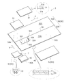
- FIG. 5 is an exploded perspective view showing each member constituting the armband 3.
- FIG. 6 is a perspective view showing a manufacturing process of each member shown in FIG.
- FIG. 7 shows a structural example of the manufactured armband portion 3
- FIG. 7A is a perspective view showing the inner surface side of the armband portion 3
- FIG. 7C is a perspective view showing the outer surface side
- FIG. 7C is a view showing a cross section taken along line AA of the armband portion 3 shown in FIG. 7A.
- the armband portion 3 includes a main body member forming sheet 50, a sheet-like contact member 51, a sheet-like sealing member 52, a male member 61 of the hook-and-loop fastener 60, and a hook-and-loop fastener 60.
- the male member 61 of the surface fastener 60 can be detachably attached to the female member 62 of the surface fastener 60.
- the male member 61 of the surface fastener 60 is one member of the surface fastener
- the female member 62 of the surface fastener 60 is the other member of the surface fastener.
- a main body member forming sheet 50 shown in FIG. 5 is a rectangular sheet, and includes a rectangular first surface portion 50A and a rectangular second surface portion 50B.
- the first surface portion 50A is a surface portion on the outer surface side of the armband portion 3 shown in FIG.
- the second surface portion 50 ⁇ / b> B is a surface portion on the inner surface side of the armband portion 3, and is a surface portion that directly touches the skin (skin) of the upper arm T.
- the V direction shown in FIG. 5 is the width direction of the armband portion 3, and the X direction is the length direction of the armband portion 3.
- the first surface portion 50A and the second surface portion 50B are separated by a center fold line 59 that is parallel to the longitudinal direction X.
- the first surface portion 50A and the second surface portion 50B are folded in the direction of the arrow RR shown in FIG. 6 along the center fold line 59 and overlap each other, thereby forming a rectangular main body member 80 as shown in FIG. .
- the main body member forming sheet 50 preferably has a double structure having a first sheet layer 71 and a second sheet layer 72.
- the first sheet layer 71 is an inner layer
- the second sheet layer 72 is an outer layer.
- the first sheet layer 71 is made of, for example, a polyurethane resin
- the second sheet layer 72 is made of, for example, a nylon resin.
- the first sheet layer 71 is not limited thereto, and may be, for example, polyester.
- This nylon resin is a trade name of DuPont, USA, and is a general name for polyamide fibers (resins). It has high water absorption, high crystallinity, excellent chemical resistance, excellent toughness, and impact resistance. And flexibility.
- the first sheet layer 71 is not limited to polyurethane resin, but can be made of natural rubber, synthetic rubber, elastomer, PVC (polyvinyl chloride), or the like.
- the reason why the first sheet layer 71 is made of, for example, urethane resin is that it can be inflated by forming an air bag for ischemia (large bag) and putting in air, and the air does not escape. It is for doing so.
- the second sheet layer 72 is made of nylon resin, for example, because it covers the first sheet layer 71 and directly touches the skin of the upper arm T of the patient (measured person) shown in FIG. This is because importance is placed on flexibility and flexibility.
- a sheet-like contact member 51 shown in FIG. 5 includes a first layer 51A and a second layer 51B.
- the first layer 51A is, for example, nylon
- the second layer 51B is, for example, a urethane resin, but is not limited thereto.
- the sheet-like sealing member 52 is, for example, a urethane resin, but is not limited thereto.
- a cut portion 50 ⁇ / b> C is formed in the second surface portion 50 ⁇ / b> B of the main body member forming sheet 50.
- a lid member 50K is formed in the cut portion 50C by cutting the three side portions 50F, 50G, and 50H.
- an air bag 40 for detecting arterial pulsation is inserted inside the lid member 50K.
- the air bag 40 for detecting arterial pulsation is positioned between the first surface portion 50A and the second surface portion 50B of the main body member forming sheet 50.
- a thin support plate 42 made of metal or plastic is fixed to an air bag 40 for detecting arterial pulsation via a double-sided tape 41 inside an air bag member 40A.
- a large pressure fluctuation in the ischemic bladder 20 is not transmitted to the arterial pulsation detecting bladder 40.
- a minute pressure fluctuation in the air bag 40 for detecting arterial pulsation can be detected without being influenced by a large pressure fluctuation in the air bag 20 for ischemia.
- the air bag 40 for detecting arterial pulsation has a function that can be brought into close contact with the bare skin of the upper arm T of the patient. As shown in FIGS.
- the abutting member 51 is fixed to the inner surface 50N of the second surface portion 50B of the main body member forming sheet 50 by, for example, high frequency fusion. Accordingly, the air bag 40 for detecting arterial pulsation is covered with the abutting member 51 in a state where the air bag 40 for detecting arterial pulsation is inserted inside the lid member 50K. For this reason, the air bag 40 for detecting arterial pulsation is built in the air bag 20 for ischemia.
- FIG. 8 shows an example of the manufacturing process of the armband portion 3.
- the male member 61 of the surface fastener 60 is disposed on the outer surface 50M of the first surface portion 50A of the main body member forming sheet 50, and the male member 61 is disposed on the first surface portion 50A.
- it is firmly attached by sewing using the thread 80 shown in FIG.
- fixing the male member 61 to the first surface portion 50A by sewing is improved as compared with the case where the male member 61 is fixed by fusion (welding), which improves the mounting strength of the male member 61 to the first surface portion 50A. This is because it can be done.
- the thread 80 passes through the male member 61 and the first surface portion 50A of the surface fastener 60 by sewing with the thread 80, the through-hole 80R is opened, and in this state, the outer side 61P of the male member 61 and the first Air passes between the surface portion 50A and the inner surface 50S side. Therefore, in order to prevent air from passing through the through-hole 80R, as shown in FIG. 8B, the sheet-like sealing member 52 is fixed to the inner surface 50S of the first surface portion 50A by, for example, high-frequency fusion. Is done.
- the sheet-like sealing member 52 can block the through-hole 80R through which the thread 80 has passed, so that air passes between the outer side 61P of the male member 61 and the inner surface 50S side of the first surface portion 50A. Can be surely prevented.
- the use of the sheet-like sealing member 52 to secure the air tightness (or liquid tightness) of the first surface portion 50A so that air does not pass through will be described later with reference to FIG. This is to ensure the sealing property of the air bag 20 for ischemia shown in FIG.
- the air bag 40 for detecting arterial pulsation is placed inside (on the upper surface side in FIG. 5) the lid member 50 ⁇ / b> K of the second surface portion 50 ⁇ / b> B of the main body member forming sheet 50. . 8C and 8D, the abutting member 51 is placed on the inner surface 50N of the second surface portion 50B and fixed to the inner surface 50N by, for example, high frequency welding (high frequency welding). . Moreover, the lid member 50K is fixed to the abutting member 51 by, for example, high frequency fusion 50R.
- the air bag 40 for detecting arterial pulsation can be sealed airtight (liquid tight) by the lid member 50K and the contact member 51, and air can pass between the outer side 50P and the inner side 51P. There is no.
- the air for ischemia shown in FIG. 7A is to secure the sealing performance so that air does not pass through the region of the lid member 50K and the air bag 40 for detecting arterial pulsation. This is to ensure the sealing performance of the bag 20.
- the manufacturing order can be arbitrarily changed.
- FIG. 9 shows an example of the high-frequency fused portions 90, 90 ⁇ / b> B, 91, 92, 93, 94 in the main body member 80.
- the first surface portion 50A and the second surface portion 50B shown in FIG. 6 are folded in the direction of the arrow RR shown in FIG. 6 by the bent portion 95 along the center fold line 59, and overlap each other.
- a rectangular main body member 80 is formed.
- the first surface portion 50A and the second surface portion 50B are formed.
- the high-frequency fused portions 90, 90B, 91, 92, 93, 94 and the bent portion 59 are divided into the main body member 80, the air bag 20 for ischemia, and the arm winding portions 96 and sealed. It has stopped. That is, as shown in FIGS. 7A and 7B, the armband main body member 80 includes the ischemic air bag 20 and the arm winding portion 96.
- the blood-insufficiency air bag 20 is hermetically sealed by the high-frequency fused portion 90B of the bent portion 95 and the high-frequency fused portions 90, 91, and 94.
- the tube 6 is airtightly connected to the tube connection hole 20 ⁇ / b> H of the ischemic air bladder 20.
- FIG. 10 is a cross-sectional view taken along the line BB showing the vicinity of the air bag 40 for detecting arterial pulsation and the air bag 20 for ischemia in FIG.
- the air bag 40 for detecting arterial pulsation is disposed so as to overlap the air bag 20 for ischemia using a contact member 51.
- the arm winding portion 96 is formed to be sealed by a bent portion 95 and high frequency fusion portions 92, 93, 94.
- the female member 62 of the hook-and-loop fastener 60 is sewn using the thread 99 as shown in FIG.
- the second surface portion 50B is attached to the outer surface 50Q.
- the female member 62 is fixed to the outer surface 50Q of the second surface portion 50B by sewing using the thread 99, so that a through hole 98 is formed in a portion through which the thread 99 is passed.
- the through hole 98 is formed to penetrate from the outside of the first surface portion 50A to the first surface portion 50A, the second surface portion 50B, and the outside of the female member 62 of the surface fastener 60.
- the through hole 98 is formed so as to penetrate from the outside of the first surface portion 50A of the arm winding portion 96 to the outside of the first surface portion 50A, the second surface portion 50B, and the female member 62 of the surface fastener 60. Because of the reason.
- the arm winding portion 96 shown in FIG. 9 (A) is different from the air bag 20 for ischemia and is a portion where air does not flow in, that is, a portion which does not expand when the upper arm is pressurized. In order to wind it securely, it is desirable to prevent air from entering the arm winding portion 96.
- the high-frequency fusion portions 90, 90 B, 91, 92, 93, 94 and the bent portion 95 are provided with the ischemic air bag 20 and the arm winding portion 96. If it is formed so that it can be divided and sealed, it is difficult to push all the air out of the arm-wound portion 96 so that no air enters the arm-wound portion 96 at all.
- the through hole 98 is formed so as to penetrate the front and back of the arm winding portion 96, so that the arm winding portion is utilized using the through hole 98.
- the air which is to remain in 96 can be pushed out completely.
- there is an advantage that air bleedability from the arm winding portion 96 is improved.
- the arm winding portion 96 of the arm band portion 3 does not cause unnecessary swelling due to residual air, the arm band portion 3 can be reliably and easily wound so as to be in close contact with the upper arm T of the patient. .
- a different size can be prepared in consideration of a patient's arm circumference dimension.
- the size of the armband portion 3 is, for example, SS size, S size, M size, L size, and LL size from small to large.
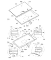
- FIG. 11A is a perspective view showing an inner surface side of the arm band portion 3 where the pull-in preventing member 300 is disposed
- FIG. 11B is an arm band portion 3 where the pull-in preventing member 300 is disposed. It is a perspective view which shows the outer surface side.
- FIG. 12 is a perspective view showing a structural example in which the pull-in preventing member 300 is attached to the inner surface side of the armband portion 3. In the specific example shown in FIG.
- the pull-in preventing member 300 is on the inner surface side of the armband portion 3 and covers the entire air bag 20 of the main body member 80.
- the winding part 96 is attached to the main body member 80 so as not to be covered.
- the inner surface side of the armband portion 3 is the surface on the side where the skin of the upper arm directly touches.
- the pull-in preventing member 300 shown in FIGS. 11 and 12 is configured so that the arm band 3 is wound around the bare skin of the upper arm T and air is fed into the air bag 20 for pressurization to pressurize the upper arm T. Even if deep wrinkles occur at a specific inner portion, the frictional force between the arm band 3 and the skin of the upper arm T is reduced so that a part of the skin of the upper arm T is not drawn into the deep wrinkles. Is attached to do.
- the pull-in preventing member 300 is a thin sheet material made of a soft and slippery material because it directly touches the skin of the upper arm T. For example, a chemical fiber such as polyester, a non-woven fabric or a paper material can be used. It is not limited to.
- the pull-in prevention member 300 is a rectangular member, and has four side portions 310, 311, 314, 310B. These four side portions 310, 311, 314, 310B are portions corresponding to the high-frequency fusion portions 90, 91, 94, 90B of the armband portion 3, respectively. As shown in FIGS. 12 (A) to 12 (B), the pull-in prevention member 300 covers the air bag 20 for ischemia and the air bag 40 for detecting arterial pulsation. Moreover, as shown in FIG. 11B, the three sides 310, 311, 310 B of the four sides 310, 311, 314, 310 B of the pull-in prevention member 300 are the high-frequency fused portions 90 of the armband 3.
- 91, 90B are folded back to form folded portions 310R, 311R, 310BR.
- the four sides 310, 311, 310 B, 314 of the pull-in prevention member 300 are threaded with respect to the high-frequency fused portions 90, 91, 90 B, 94 of the armband portion 3. 400 is firmly attached by sewing (sewing).
- the attachment structure of the four sides 310, 311, 310B, and 314 of the pull-in preventing member 300 will be described in detail with reference to FIG.
- the side portion 310, the high frequency fusion portion 90, and the folded portion 310R of the side portion 310 of the pull-in prevention member 300 are stitched together by the thread 400.
- the side portion 311, the high-frequency fusion portion 91, and the folded portion 311 ⁇ / b> R of the side portion 311 are stitched together with the thread 400.
- the side portion 310B of the pull-in preventing member 300, the high frequency fusion portion 90B, and the folded portion 310BR of the side portion 310B are stitched together by the thread 400.
- the side portion 314 of the pull-in prevention member 300 and the high-frequency fusion portion 94 are stitched together by the thread 400.
- the four sides 310, 311, 310 ⁇ / b> B, and 314 of the pull-in prevention member 300 are stitched using the thread 400 using the high-frequency fused portions 90, 91, 90 ⁇ / b> B, and 94 of the armband portion 3. ing.
- the four sides 310, 311, 310 ⁇ / b> B, 314 of the pull-in prevention member 300 can be reliably attached to the main body member 80 using the high-frequency fused portions 90, 91, 90 ⁇ / b> B, 94.
- the through hole 410 formed for the thread 400 to pass through is formed through the high-frequency fused portions 90, 91, 90 B, 94.
- the through hole 410 is formed, the supplied air in the air bag 20 for ischemia does not escape from the through hole 410. Therefore, the air in the air bag 20 for ischemia does not leak to the outside through the through-hole 410, so that the blood issuance function exerted by supplying air into the air bag 20 for blood is guaranteed. .
- FIG. 13 shows a state in which the arm band 3 is wound around the skin of the upper arm T of the patient via the pull-in preventing member 300.
- FIG. 14 shows an example of a procedure for winding the armband portion 3 into the bare skin of the upper arm T of the patient via the prevention member 300.
- the medical staff wraps and fixes the armband portion 3 directly around the skin of the upper arm T of the patient as follows.
- the arm band portion 3 to be wound around the upper arm T has the first surface portion 50A on the lower side, the second surface portion 50B on the upper side, and the second surface portion 50B, as shown in FIG.
- the side is applied from the lower side of the upper arm T.
- the drawing-in preventing member 300 is on the upper side and comes to face the skin of the upper arm T.
- the medical worker holds the start end portion 159 of the armband portion 3 by hand and winds the armband portion 3 around the upper arm T along the R1 direction.
- the air bag 40 for detecting arterial pulsation is positioned according to the position of the artery of the upper arm T, so that the air bag 40 for detecting arterial pulsation can be accurately positioned with respect to the artery of the upper arm T. .
- the pull-in preventing member 300 on the second surface part 50B side directly contacts the skin of the upper arm T.
- the medical worker holds the terminal portion 169 of the armband portion 3 by hand and winds the armband portion 3 around the upper arm T along the R2 direction.
- the female member 62 of a hook-and-loop fastener mentioned above is detachably attached to the male member 61 of the hook-and-loop fastener as shown in FIG. Since the female member 61 of the hook-and-loop fastener and the male member 62 of the hook-and-loop fastener are detachably engaged, the arm band portion 3 can be directly wound around the bare skin of the upper arm T and fixed so as not to be displaced. In this case, the pull-in preventing member 300 is in close contact with the skin of the upper arm T. 7A and FIG.
- the air remaining in the arm winding portion 96 is exposed to the outside of the arm winding portion 96 using the through hole 98 shown in FIG. 7C. Can be extruded. For this reason, since the arm winding portion 96 does not cause unnecessary swelling due to residual air, the arm band portion 3 can be reliably and easily wound so as to be in close contact with the upper arm T.
- the medical staff presses the power switch 9 shown in FIG. 3 and the mode switch 10 while the armband 3 is held in the correct posture with respect to the upper arm T. Select the desired mode with.
- FIG. 2 by repeating the operation of holding and releasing the air balloon 5 while supporting the extension portion 14 with the finger of the hand H, the air from the air balloon 5 is exchanged with the piping in the sphygmomanometer body 2. Air is sent through the tubes 6 and 7 into the air bag 20 for ischemia and the air bag 40 for detecting arterial pulsation in the armband 3. As a result, the pressure sensor 110 shown in FIG.
- the air bag 20 for ischemia and the air bag 40 for detecting arterial pulsation can apply pressure to the upper arm T side, which is the inner side in the radial direction, and the pressure generated by the ischemic air bag 20 and arterial pulsation are detected.
- the pressure generated by the air bag 40 can be applied to the upper arm T without escaping to the outside of the armband portion 2, and accurate blood pressure measurement can be performed.
- FIG. 15 shows an example in which the pressure applied to the upper arm T by the air bag 20 for ischemia changes with time.
- Air is sent into the air bag 20 for detecting ischemia and the air bag 40 for detecting arterial pulsation shown in FIG. 4 by repeating the operation of grasping and releasing the air balloon 5 shown in FIG. Therefore, as shown in FIG. 15, the pressure in the air bag 20 for ischemia in the armband portion 3 increases during the pressure increase period t1.
- the control unit 100 in FIG. 4 determines that the pressurization is currently being performed, and instructs the drive unit 113 to close the electromagnetic valve 116. And the operation
- the controller 100 waits for the natural pressure reducing period t2, and then determines that the pressure detected by the pressure sensor 110 in FIG. 4 is in a reduced pressure state during the optimum speed pressure reducing period t3.
- the unit 113 is commanded to open the electromagnetic valve 116 so that the pressure reduction speed becomes a predetermined value.
- the control unit 100 shown in FIG. 4 receives a maximum blood pressure value (SYS) by a signal from the pressure sensor 110.
- SYS maximum blood pressure value
- a minimum blood pressure value (D1A) and a pulse value are acquired.
- the control unit 100 in FIG. 4 operates the forced exhaust valve 117 to force the air in the air bag 20 for ischemia in the armband 3 and the air bag 40 for detecting arterial pulsation. Evacuate to eliminate pressure.
- the medical staff may remove the armband 3 from the patient's upper arm T in the order of FIG. 14 (C), FIG. 14 (B), and FIG. 14 (A). That is, as shown in FIG. 14C, the medical worker holds the end portion 169 of the armband portion 3 by hand and peels the end portion 169 of the armband portion 3 along the R3 direction. Accordingly, as shown in FIG. 14B, the female member 62 of the surface fastener on the terminal end 169 side of the armband portion 3 is peeled off from the male member 61 of the surface fastener on the start end portion 159 side of the armband portion 3. Can do. Then, as shown in FIG. 14 (B), the medical staff holds the starting end portion 159 of the armband portion 3 by hand and separates it from the upper arm T in the R4 direction, as shown in FIG. 14 (A). The part 3 can be easily removed from the upper arm T.
- the blood-insufficiency air bag 20 is formed to be sealed by the bent portion 95 and the high-frequency fused portions 90, 90B, 91, 94.
- the air bag 40 for detecting arterial pulsation can be sealed by the lid member 50K and the contact member 51, and air does not pass between the outer side 50P and the inner side 51P. Therefore, the air bag 20 for ischemia and the air bag 40 for detecting arterial pulsation are air-tight and liquid-tight. For this reason, since the armband part 3 can be disinfected with a disinfectant or can be washed with a cleaning liquid, the armband part 3 can be kept clean.
- FIG. 16A shows a state near the skin of the upper arm T at the time of blood pressure measurement by the arm band portion 3 having the pull-in preventing member 300 in the first embodiment of the present invention
- FIG. A state in the vicinity of the skin of the upper arm T at the time of blood pressure measurement by the arm band 1003 is shown.
- the armband 3 is attached to the patient's upper arm T, air is introduced into the air bag 20 for ischemia, and the upper arm T is pressurized.
- FIG. 17 shows a second embodiment of the present invention.
- the four side portions 310, 311, 310 ⁇ / b> B, 314 of the pull-in prevention member 300 use the high frequency fusion portions 90, 91, 90 ⁇ / b> B, 94 of the armband portion 3. Since it is stitched using the thread 400, it can be securely attached.
- the four side portions 310, 311, 310 ⁇ / b> B, 314 of the pull-in prevention member 300 are the high frequency fusion portions 90, 91, 90 ⁇ / b> B of the armband portion 3.
- 94 is fixed by using a fusion part 550 by high-frequency fusion instead of sewing using a thread. By doing so, the pull-in preventing member 300 can be more easily fixed to the inner surface of the armband portion 3.
- FIG. 18 shows a third embodiment of the present invention.
- the four side portions 310, 311, 310 ⁇ / b> B, 314 of the pull-in prevention member 300 are compared to the high-frequency fusion portions 90, 91, 90 ⁇ / b> B, 94 of the armband portion 3.
- it is fixed using a double-sided adhesive tape 700.
- the pull-in preventing member 300 can be more easily fixed to the inner surface of the armband portion 3.
- the pull-in preventing member 300 uses the double-sided pressure-sensitive adhesive tape 700, so that it can be attached to and detached from the armband portion 3.
- the used pull-in preventing member 300 can be removed from the double-sided adhesive tape 700 and a new pull-in preventing member 300 can be attached to the inner surface of the armband portion 3 using the double-sided adhesive tape 700.
- the pull-in prevention member 300 can be easily and appropriately replaced, whether it is a patient or a medical professional.
- a material of the pull-in preventing member 300 a chemical fiber, a non-woven fabric, or a thin paper material can be used. When a plurality of patients use sphygmomanometers, the pull-in preventing member 300 can be replaced, so that the armband portion 3 can be used more cleanly.
- the sphygmomanometer 1 has an arm band 3.
- the armband portion 3 is disposed in the body member 80 having the blood-insufficing air bag 20 for blocking the upper arm by supplying air, and the blood-insulating air bag of the body member.
- An air bag 40 for detecting arterial pulsation for detecting arterial pulsation is provided, and the main body member 80 has wrinkles generated on the inner surface of the arm band T when the upper arm T is pressurized by the arm band 3.
- a pull-in preventing member 300 for preventing the T skin from being pulled in is disposed.
- the main body member is provided with a pull-in preventing member for preventing the upper arm skin from being drawn into the wrinkles generated on the inner surface of the arm band portion when the upper arm is pressed by the arm band portion.
- the frictional force between the inner surface of the belt portion and the upper arm skin can be reduced. For this reason, even if the inner surface of the arm band moves when the upper arm is pressurized, it is possible to reduce the movement of the upper arm skin together. Therefore, even if deep wrinkles are formed on the inner surface of the armband part, there is no possibility that a part of the upper arm skin is drawn into the deep wrinkles, so the armband part is attached to the upper arm of the patient to measure blood pressure. In this case, internal bleeding can be prevented without causing the patient to feel uncomfortable.
- the pull-in preventing member is disposed on the air bag for ischemia and the air bag for detecting arterial pulsation of the main body member.
- the pull-in preventing member is disposed on the air bag for ischemia and the air bag for detecting arterial pulsation of the main body member that touches the skin of the upper arm, the upper arm is added by injecting air into the air bag for ischemia. When pressure is applied, there is no risk that a part of the skin of the arm will be drawn into this deep wrinkle. Occurrence can be prevented.
- the main body member has a first surface portion and a second surface portion that overlaps the first surface portion, and the first surface portion and the second surface portion in contact with the skin of the upper arm are provided with an air bag for ischemia using a fusion portion.
- the pull-in preventing member is fixed to the fusion part by stitching or fusion with a thread. Thereby, since the drawing-in preventing member is fixed to the fused portion by stitching or fusing with a thread, the drawing-in preventing member can be reliably fixed to the main body member.
- the main body member has a first surface portion and a second surface portion that overlaps the first surface portion, and the first surface portion and the second surface portion in contact with the skin of the upper arm are provided with an air bag for ischemia using a fusion portion.
- the pull-in prevention member is detachably fixed to the fused portion. Therefore, since the pull-in preventing member is detachably fixed to the fusion part, the pull-in preventing member can be securely fixed to the main body member, and the used pull-in preventing member becomes a new pull-in preventing member. Since it can be easily replaced, it is hygienic.
- It has a blood pressure monitor body connected to the armband air bag for ischemia and an air bag for detecting arterial pulsation using a tube.
- the blood pressure monitor body is attached to the housing and the housing.
- the present invention is not limited to the above embodiment, and various modifications can be made without departing from the scope of the claims.
- the illustrated sphygmomanometer is of a manual pressurization type, but the sphygmomanometer of the present invention is not limited to this.
- the automatic sphygmomanometer has an arm band and a sphygmomanometer body that is separate from the arm band, and the arm band is wound around the upper arm of a patient (a person to be measured).
- air can be sent from the sphygmomanometer main body through the tube to the air bag for ischemia and the air bag for detecting arterial pulsation.
- the male member 61 of the hook-and-loop fastener 60 is one member of the hook-and-loop fastener and is disposed in the blood-insulating air bag 20, and the female member 62 of the hook-and-loop fastener 60 is the other member of the hook-and-loop fastener and the arm winding portion. 96.
- the present invention is not limited to this, and conversely, the female member of the hook-and-loop fastener 60 is one member of the hook-and-loop fastener and is disposed in the air bag 20 for ischemia, and the male member of the hook-and-loop fastener 60 is the other member of the hook-and-loop fastener. You may make it arrange
- FIG. A part of each configuration of the above embodiment can be omitted, or can be arbitrarily combined so as to be different from the above.
Landscapes
- Health & Medical Sciences (AREA)
- Life Sciences & Earth Sciences (AREA)
- Cardiology (AREA)
- Medical Informatics (AREA)
- Surgery (AREA)
- Biophysics (AREA)
- Pathology (AREA)
- Engineering & Computer Science (AREA)
- Biomedical Technology (AREA)
- Heart & Thoracic Surgery (AREA)
- Physiology (AREA)
- Molecular Biology (AREA)
- Physics & Mathematics (AREA)
- Animal Behavior & Ethology (AREA)
- General Health & Medical Sciences (AREA)
- Public Health (AREA)
- Veterinary Medicine (AREA)
- Vascular Medicine (AREA)
- Ophthalmology & Optometry (AREA)
- Measuring Pulse, Heart Rate, Blood Pressure Or Blood Flow (AREA)
Abstract
【課題】腕帯部を患者の上腕に装着して血圧測定をする際に、患者が不快に感じることなく、内出血の発生を防止できる血圧計を提供する。 【解決手段】血圧計1の腕帯部3は、空気を供給することで上腕を阻血するための阻血用空気袋20を有する本体部材80と、本体部材の阻血用空気袋に配置され、空気を供給することで上腕Tの動脈の拍動を検出するための動脈拍動検出用の空気袋40を備え、本体部材80には、腕帯部3により上腕Tを加圧する際に腕帯部Tの内面に生じるシワに上腕Tの皮膚を引き込むことを防止するための引き込み防止部材300が、配置されている。
Description
本発明は、腕帯部を巻き付けて患者の血圧を測定する血圧計に関する。
医療機関で看護師等の医療従事者が使用する血圧計としては、腕帯部へ送気するための送気球と血圧計本体部とを一体化した手動加圧方式のものがある。この血圧計の腕帯部は動脈を阻血するための阻血用空気袋と、この阻血用空気袋に付けてある動脈拍動検出用の空気袋を有している。医療従事者が手動で送気球を握ったり離したりすることで、血圧計本体部からチューブを通して腕帯部内の阻血用空気袋に空気を送って、患者の上腕を加圧して血圧を測定する。医療従事者は送気球を片手で簡単に操作でき、腕帯部内の阻血用空気袋に空気を送る際に、空気を送るためのモータが不要であるので、夜間でも静かな血圧測定を行うことができる(特許文献1を参照)。
ところで、従来の血圧計の腕帯部を患者(被測定者)の上腕に巻き付けて血圧測定を行う場合に、阻血用空気袋(大バッグ)に空気を入れて上腕を加圧すると、腕帯部の内面が移動して腕帯部のある箇所に折れ曲がり部分が生じる。この腕帯部の内面の折れ曲がり部分では、深いシワが生じる。腕帯部の内面側に深いシワが生じると、腕帯部の内面とともに上腕の皮膚の一部分が引っ張られて、上腕の皮膚の一部分が深いシワに引き込まれてしまうことがある。このため、患者は血圧測定時に不快に感じ、場合によっては上腕に内出血を生じるおそれがある。
そこで、本発明は、腕帯部を患者の上腕に装着して血圧測定をする際に、患者が不快に感じることなく、内出血の発生を防止できる血圧計を提供することを目的とする。
そこで、本発明は、腕帯部を患者の上腕に装着して血圧測定をする際に、患者が不快に感じることなく、内出血の発生を防止できる血圧計を提供することを目的とする。
本発明の血圧計は、腕帯部を有し、前記腕帯部を被測定者の上腕に巻いて加圧することで血圧を測定する血圧計であって、前記腕帯部は、空気を供給することで前記上腕を阻血するための阻血用空気袋を有する本体部材と、前記本体部材の前記阻血用空気袋に配置され、前記空気を供給することで前記上腕の動脈の拍動を検出するための動脈拍動検出用の空気袋とを備え、前記本体部材には、前記腕帯部により前記上腕を加圧する際に前記腕帯部の内面に生じるシワに前記上腕の皮膚が引き込まれることを防止するための引き込み防止部材が、配置されていることを特徴とする。
上記構成によれば、本体部材には、腕帯部により上腕を加圧する際に腕帯部の内面に生じるシワに上腕の皮膚を引き込むことを防止するための引き込み防止部材が、配置されているので、腕帯部の内面と上腕の皮膚との間の摩擦力を低減することができる。このため、上腕を加圧する際に腕帯部の内面が移動しても、上腕の皮膚が一緒に移動するのを減らすことができる。従って、腕帯部の内面に深いシワが形成されたとしても、上腕の皮膚の一部がこの深いシワに引き込まれるおそれがないので、腕帯部を患者の上腕に装着して血圧測定をする際に、患者が不快に感じることなく、内出血の発生を防止できる。
上記構成によれば、本体部材には、腕帯部により上腕を加圧する際に腕帯部の内面に生じるシワに上腕の皮膚を引き込むことを防止するための引き込み防止部材が、配置されているので、腕帯部の内面と上腕の皮膚との間の摩擦力を低減することができる。このため、上腕を加圧する際に腕帯部の内面が移動しても、上腕の皮膚が一緒に移動するのを減らすことができる。従って、腕帯部の内面に深いシワが形成されたとしても、上腕の皮膚の一部がこの深いシワに引き込まれるおそれがないので、腕帯部を患者の上腕に装着して血圧測定をする際に、患者が不快に感じることなく、内出血の発生を防止できる。
好ましくは、前記引き込み防止部材は、前記本体部材の前記阻血用空気袋と前記動脈拍動検出用の空気袋の上に配置されていることを特徴とする。
上記構成によれば、引き込み防止部材は、上腕の皮膚に触れる本体部材の阻血用空気袋と動脈拍動検出用の空気袋の上に配置するだけで、腕の皮膚の一部がこの深いシワに引き込まれるのを防止できる。
上記構成によれば、引き込み防止部材は、上腕の皮膚に触れる本体部材の阻血用空気袋と動脈拍動検出用の空気袋の上に配置するだけで、腕の皮膚の一部がこの深いシワに引き込まれるのを防止できる。
好ましくは、前記本体部材は、第1面部と前記第1面部に重なっている第2面部を有し、前記上腕の皮膚に接する前記第2面部には融着部を用いて前記阻血用空気袋が設けられており、前記引き込み防止部材は、前記融着部に対して、糸による縫合あるいは融着により固定されていることを特徴とする。
上記構成によれば、引き込み防止部材は、融着部に対して糸による縫合あるいは融着により固定されているので、引き込み防止部材は本体部材に対して確実に固定することができる。
上記構成によれば、引き込み防止部材は、融着部に対して糸による縫合あるいは融着により固定されているので、引き込み防止部材は本体部材に対して確実に固定することができる。
好ましくは、前記本体部材は、第1面部と前記第1面部に重なっている第2面部を有し、前記上腕の皮膚に接する前記第2面部には融着部を用いて前記阻血用空気袋が設けられており、前記引き込み防止部材は、前記融着部に対して、着脱可能に固定されていることを特徴とする。
上記構成によれば、引き込み防止部材は、融着部に対して着脱可能に固定されているので、引き込み防止部材は本体部材に対して確実に固定でき、使用済みの引き込み防止部材を新たな引き込み防止部材へ簡単に交換できるので、衛生的に良い。
上記構成によれば、引き込み防止部材は、融着部に対して着脱可能に固定されているので、引き込み防止部材は本体部材に対して確実に固定でき、使用済みの引き込み防止部材を新たな引き込み防止部材へ簡単に交換できるので、衛生的に良い。
好ましくは、前記腕帯部の前記阻血用空気袋と前記動脈拍動検出用の空気袋に対してチューブを用いて接続された血圧計本体部を有し、前記血圧計本体部は、筐体と、前記筐体に取り付けられ、押すことにより前記チューブを通じて前記空気を前記阻血用空気袋と前記動脈拍動検出用の空気袋に送る送気球とを有することを特徴とする。
上記構成によれば、医療従事者が一方の手で送気球を持った状態で、医療従事者は他方の片手だけで腕帯部を上腕に容易に位置決めしながら巻き付けることができる。
上記構成によれば、医療従事者が一方の手で送気球を持った状態で、医療従事者は他方の片手だけで腕帯部を上腕に容易に位置決めしながら巻き付けることができる。
本発明は、腕帯部を患者の上腕に装着して血圧測定をする際に、患者が不快に感じることなく、内出血の発生を防止できる血圧計を提供することができる。
以下に、本発明の好ましい実施形態を、図面を参照して詳しく説明する。
尚、以下に述べる実施の形態は、本発明の好適な具体例であるから、技術的に好ましい種々の限定が付されているが、本発明の範囲は、以下の説明において特に本発明を限定する旨の記載がない限り、これらの態様に限られるものではない。
尚、以下に述べる実施の形態は、本発明の好適な具体例であるから、技術的に好ましい種々の限定が付されているが、本発明の範囲は、以下の説明において特に本発明を限定する旨の記載がない限り、これらの態様に限られるものではない。
(第1実施形態)
図1は、本発明の血圧計の好ましい第1実施形態を示す斜視図である。図2は、図1に示す血圧計の正面図である。
図1に示すように、血圧計1は、看護師等の医療従事者により手動加圧方式で患者の上腕Tに装着された腕帯内の空気袋を加圧することで、被測定者である患者の血圧測定を行うことができる。この手動加圧方式の血圧計1は、送気球(加圧部)と血圧計本体部とが一体化されており、医療従事者は片手で送気球を加圧操作することができ、モータ音が無いために、夜間でも静かに血圧測定を行うことができる。
図1は、本発明の血圧計の好ましい第1実施形態を示す斜視図である。図2は、図1に示す血圧計の正面図である。
図1に示すように、血圧計1は、看護師等の医療従事者により手動加圧方式で患者の上腕Tに装着された腕帯内の空気袋を加圧することで、被測定者である患者の血圧測定を行うことができる。この手動加圧方式の血圧計1は、送気球(加圧部)と血圧計本体部とが一体化されており、医療従事者は片手で送気球を加圧操作することができ、モータ音が無いために、夜間でも静かに血圧測定を行うことができる。
医療従事者は、この血圧計1を用いる際には、患者の病態に応じて3つの測定モードを選択することができる。3つの測定モードとは、ノーマルモード、スローモード、そして聴診モードである。
ノーマルモードは、自動測定により血圧測定をよりスピーディーに行うことができるモードである。スローモードは、自動測定により加圧後の減圧速度を、ノーマルモードの加圧後の減圧速度に比べて遅く設定して、低血圧の患者や脈拍の弱い患者の血圧測定を行うことができるモードである。そして、聴診モードは、自動測定は行わずに、医療従事者が聴診器を用いた聴診法により血圧測定をするモードである。
ノーマルモードは、自動測定により血圧測定をよりスピーディーに行うことができるモードである。スローモードは、自動測定により加圧後の減圧速度を、ノーマルモードの加圧後の減圧速度に比べて遅く設定して、低血圧の患者や脈拍の弱い患者の血圧測定を行うことができるモードである。そして、聴診モードは、自動測定は行わずに、医療従事者が聴診器を用いた聴診法により血圧測定をするモードである。
図1と図2に示す血圧計1における測定方式は、オシロメトリック法(いわゆる阻血用空気袋と動脈拍動検出用の空気袋を用いるダブルカフ方式)であり、図1に示すように測定対象部位は、被測定者である患者の上腕Tである。使用する電源としては、例えば乾電池を用いている。
図1と図2に示すように、血圧計1は、血圧計本体部2と、腕帯部3を有している。血圧計本体部2は、筐体4と送気球5を有している。送気球5は、医療従事者が加圧操作することで内部の空気を送ることができる加圧部であり、伸縮性を有する材料で作られている。送気球5は、この例えばゴム気球である。
図1と図2に示すように、血圧計1は、血圧計本体部2と、腕帯部3を有している。血圧計本体部2は、筐体4と送気球5を有している。送気球5は、医療従事者が加圧操作することで内部の空気を送ることができる加圧部であり、伸縮性を有する材料で作られている。送気球5は、この例えばゴム気球である。
この血圧計1の腕帯部3は、患者の上腕Tに装着して阻血用空気袋(大バッグ)に空気を入れて上腕Tを加圧しても、腕帯部3の内面側に生じる深いシワに上腕Tの皮膚の一部分が引き込まれるのを防止するために、後で説明するが、腕帯部3の内面側には、滑り易い材質から作られている引き込み防止部材を配置している。これにより、腕帯部3の内面と上腕Tの皮膚との間に生じる摩擦力を低減でき、腕帯部3の内面を引き込み防止部材を用いて滑り易くすることができる。従って、上腕Tの皮膚の一部分が、腕帯部3の内面側に生じる深いシワによって引っ張り込まれないので、腕帯部3により加圧して血圧測定を行う場合に、患者が不快に感じることなく、腕帯部3の装着使用感を向上でき、内出血の発生を防止できる機能を有する。
図1と図2に示す血圧計本体部2の筐体4は、プラスチック製であり、長方形状の表示部8と、電源スイッチ9と、モードスイッチ10と、排気スイッチ11を有している。この表示部8は、例えば液晶表示装置や有機EL(エレクトロルミネッセンス)表示装置等であり、単色表示であっても、カラー表示であっても良い。この表示部8は、最高血圧値、最低血圧値、脈拍数、そして上述した3つの測定モードのどのモードが選択されているかを表示することができる。
図1と図2に示す電源スイッチ9は、医療従事者が押すことで、血圧計本体部2の電源をオンしたり、オフすることができる。モードスイッチ10は、医療従事者が押すことで、測定モードを上述したノーマルモード、スローモード、そして聴診モードの内の任意のモードに切り替えることができる。排気スイッチ11は、医療従事者が押すことで、後で説明する腕帯部3内の阻血用空気袋内の空気と動脈拍動検出用の空気袋内の空気を強制的に排出することができる。
図1に示す2本のチューブ6,7は、血圧計本体部2の筐体4と腕帯部3とを接続しているフレキシブルなチューブである。チューブ6はチューブ7に比べて太い。チューブ6の一端部6Bは、コネクタ部12を介して筐体4の上部に対して接続されている。チューブ7の一端部7Bは、プラグ7Cとコネクタ部12を介して筐体4の上部に対して接続されている。チューブ6,7の一端部6B、7B側付近は、ホルダー13により固定されている。このように、チューブ6,7がホルダー13により固定されていることにより、チューブ6,7が分離しないようにまとめているが、細いチューブ7の一端部7Bは、太いチューブ6の一端部6Bに比べて弛ませることで、チューブ6の動きにチューブ7の動きが追従できるように、チューブ7の長さには余裕を持たせてある。これにより、太いチューブ6を引き回したことで太いチューブ6が多少無理な方向に引っ張られたとしても、細いチューブ7が太いチューブ6につられて抜けてしまわない。
図1に示すように、筐体4の下部には、延長部14が下方に突出して形成されている。この延長部14は、送気球5の正面部5Sの一部を覆っている薄板状の部材である。医療従事者が図2に示すように、延長部14を手Hの指で支えながら送気球5を握ったり離したりする動作を繰り返すことにより、送気球5からの空気は、血圧計本体部2内の配管とチューブ6,7を通じて腕帯部3内の阻血用空気袋と動脈拍動検出用の空気袋に供給することができる。筐体4の両側には突出部4Tが形成されている。
図3には、血圧計本体部2の表示部8が表示できる表示項目の例を示している。
図3に示すように、表示部8は、最高血圧値表示領域8A、最低血圧値表示領域8B、脈拍表示領域8C、脈波信号表示領域8D、前回値の表示領域8E、排気中の表示領域8F、加圧不足の表示領域8G、過加圧の表示領域8H、選択中のモード表示領域8Kを有している。
図3に示す最高血圧値表示領域8Aは、加圧中および減圧中にあっては血圧の瞬時圧を表示し、最終的には最高血圧値を表示する。最低血圧値表示領域8Bは、最終的に決定された最低血圧値を表示する。
図3に示すように、表示部8は、最高血圧値表示領域8A、最低血圧値表示領域8B、脈拍表示領域8C、脈波信号表示領域8D、前回値の表示領域8E、排気中の表示領域8F、加圧不足の表示領域8G、過加圧の表示領域8H、選択中のモード表示領域8Kを有している。
図3に示す最高血圧値表示領域8Aは、加圧中および減圧中にあっては血圧の瞬時圧を表示し、最終的には最高血圧値を表示する。最低血圧値表示領域8Bは、最終的に決定された最低血圧値を表示する。
図3に示す脈拍表示領域8Cは、測定された脈拍値を表示する。脈波信号表示領域8Dは、検出された脈波信号の大きさを表示し、脈波信号の大きさは左右に移動するバー状に表示する。通常の脈を持つ患者の場合には、脈波信号の大きさの表示はリズミカルに左右に増加したり減少したりするが、不整脈を持つ患者の場合には、脈波信号の大きさの表示はリズミカルに左右に増加したり減少することはない。この脈波信号表示領域8Dを備えることで、被測定者である患者が不整脈を有するか否かを視覚的に判断することができる。
図3に示す前回値の表示領域8Eは、電源スイッチ9を押して血圧計本体部2の動作を立ち上げると点滅または点灯し、前回に測定した最高血圧値、最低血圧値、脈拍値が、最高血圧値表示領域8A、最低血圧値表示領域8B、脈拍表示領域8Cにそれぞれ表示される。そして、しばらく経過するか、あるいは送気球5を操作して送気が行われると、前回に測定した最高血圧値、最低血圧値、脈拍値の表示が消滅して、前回値の表示領域8Eは、電源スイッチ9を押して血圧計本体部2の動作を立ち上げると点滅または点灯も消滅する。排気中の表示領域8Fは、腕帯部3内の阻血用空気袋と動脈拍動検出用の空気袋の空気を急速に排気する際に点滅する。また、排気中の表示領域8Fは、排気スイッチ11が押された場合にも点滅する。
図3に示す加圧不足の表示領域8Gが、点灯または点滅している時には、腕帯部3内の圧力が血圧測定をするのに十分なレベルまで達していないことを示すので、医療従事者に対してさらに送気球5を用いて空気を送るように促すことができる。
過加圧の表示領域8Hが、点灯または点滅している時には、腕帯部3内の圧力が所定の圧力以上(例えば、320mmHg以上)になっていることを示し、医療従事者は過加圧の表示領域8Hを確認することで、加圧動作を止めるように促すことができる。
過加圧の表示領域8Hが、点灯または点滅している時には、腕帯部3内の圧力が所定の圧力以上(例えば、320mmHg以上)になっていることを示し、医療従事者は過加圧の表示領域8Hを確認することで、加圧動作を止めるように促すことができる。
図3に示す選択中のモード表示領域8Kは、モードスイッチ10を押すことで、ノーマルモード、スローモード、そして聴診モードの内のどのモードが選択されているかを表示している。このモード選択によって、排気(減圧)スピードを変えることができるようになっている。ノーマルモードが選択されると、排気スピードは例えば約5mmHg/秒に設定される。ノーマルモードでは、排気スピードが比較的速いので測定時間を比較的短くできるという利点がある。その一方で、圧力変化測定の刻みが大きいことになるので、脈拍が安定した人を測定する場合には特に問題はないが、不整脈の人の血圧を測定する場合には、脈が抜けやすいので測定誤差が大きくなる可能性がある。
そこで、スローモードが設けられており、このスローモードが選択された場合には、排気スピードをノーマルモード時の略半分付近、例えば2.0~2.5mmHg/秒に設定している。このように「スロー」モードでは通常よりゆっくり減圧することにより詳細に圧力変化を見ることができるので、脈が抜けやすい不整脈の人の測定がより正確に行うことができる。
さらに、聴診モードは、聴診器を使ってマニュアルで測定するモードであるが、この場合も通常モードの略半分程度の排気スピード、例えば2.0~3.0mmHg/秒に設定される。
さらに、聴診モードは、聴診器を使ってマニュアルで測定するモードであるが、この場合も通常モードの略半分程度の排気スピード、例えば2.0~3.0mmHg/秒に設定される。
次に、図4を参照して、血圧計1の血圧計本体部2内に配置されている制御回路ブロック例について説明する。図4は、血圧計本体部2内に配置されている制御回路ブロック例と、腕帯部3の構成例を示している。
図4に示す血圧計本体部2の筐体4の内部には、制御部100が配置されており、この制御部100は中央処理装置(CPU)を有している。制御部100は、表示部8と、電源コントロール部102と、電源スイッチ9と、モードスイッチ10と、排気スイッチ11と、圧力センサ110と、ROM(読み出し専用メモリ)111と、RAM(ランダムアクセスメモリ)112と、駆動部113と、ブザー114に電気的に接続されている。
図4に示す血圧計本体部2の筐体4の内部には、制御部100が配置されており、この制御部100は中央処理装置(CPU)を有している。制御部100は、表示部8と、電源コントロール部102と、電源スイッチ9と、モードスイッチ10と、排気スイッチ11と、圧力センサ110と、ROM(読み出し専用メモリ)111と、RAM(ランダムアクセスメモリ)112と、駆動部113と、ブザー114に電気的に接続されている。
図4に示す電池115の電源は、電源コントロール部102によりコントロールされることで、制御部100に電源供給される。電池115としては、乾電池であっても、2次電池(充電池)であっても良い。しかし、好ましくは、医療従事者が片手で送気球の加圧操作を行い、しかも測定時の消費電力は0.5W程度であるため、使用する電源としては、例えば単3形乾電池(DC1.5V)または単3形充電池(DC1.5V)を1本のみ用いる。このため、新品の単3形乾電池(DC1.5V)を使用する場合、1000回程度の血圧測定が可能となり、血圧計1全体の小型化,軽量化(135g程度)が図られる。表示部8は、制御部100の指令により図3を参照しながら説明した表示項目を表示する。
図4において、後で詳しく説明するが、腕帯部3は、本体部材80を有しており、この本体部材80には、阻血用空気袋20と、動脈拍動検出用の空気袋40が設けられている。圧力センサ110は、この阻血用空気袋20内の圧力と、動脈拍動検出用の空気袋40内の圧力を検出する。圧力センサ110は、阻血用空気袋20内の圧力の変化を検出する。しかも、動脈拍動検出用の空気袋40内の圧力は、血圧測定中に生じる上腕Tの動脈拍動による動脈壁の振動により、すなわち上腕Tの動脈の脈波により変動するが、圧力センサ110はこの圧力の変動を検出する。
阻血用空気袋20は大カフともいい、動脈拍動検出用の空気袋40は小カフともいう。阻血用空気袋20には、動脈拍動検出用の空気袋40が内蔵して配置されている。血圧計1は、いわゆるダブルカフ方式の腕帯部3を有している。
阻血用空気袋20は大カフともいい、動脈拍動検出用の空気袋40は小カフともいう。阻血用空気袋20には、動脈拍動検出用の空気袋40が内蔵して配置されている。血圧計1は、いわゆるダブルカフ方式の腕帯部3を有している。
図4に示すROM111は、制御プログラムや各種のデータを予め格納している。RAM112は、演算結果や測定結果を一時的に格納する。駆動部113は、制御部100の指令により電磁バルブ116を駆動する。腕帯部3が上腕Tを加圧している場合には、圧力センサ110により検出される圧力の変動値は、測定時である減圧時の圧力の変動値に比べてかなり大きい。このため、圧力センサ110が検出する圧力の変動値が所定値以上であると、制御部100が判断すると、制御部100は現在加圧中であると判断して駆動部113に指令をして電磁バルブ116を閉める。
これに対して、圧力センサ110が検出する圧力について、所定期間内に圧力変動値(上昇値)がほぼゼロもしくは減圧状態であると制御部100が判断すると、制御部100は駆動部113に指令をして、電磁バルブ116を減圧スピードが所定値になるように開く。そして血圧計1の動作は、加圧モードから測定モードに移行することになる。
強制排気弁117は、排気スイッチ11が押されると、制御部100の指令により開くようになっている。
ブザー114は、制御部100の指令により所定の警告音を発生する。例えば、ブザー114は、血圧計本体部2の電源スイッチ9を押して表示部8が表示可能な状態になった時、モードスイッチ10を押すことによるモードの切り替え時、血圧値が決定した時、エラーが発生した時等に警告音を発生する。
強制排気弁117は、排気スイッチ11が押されると、制御部100の指令により開くようになっている。
ブザー114は、制御部100の指令により所定の警告音を発生する。例えば、ブザー114は、血圧計本体部2の電源スイッチ9を押して表示部8が表示可能な状態になった時、モードスイッチ10を押すことによるモードの切り替え時、血圧値が決定した時、エラーが発生した時等に警告音を発生する。
図4に示す強制排気弁117は、チューブ6の一端部6Bと導通管120の間に配置されている。送気球5は、マニホールド118と、分岐部119と、導通管120と、強制排気弁117を通じて、チューブ6の一端部6Bに接続されている。チューブ6の他端部6Aは、阻血用空気袋20に接続されている。また、送気球5は、マニホールド118と、分岐部119と、マニホールド121と、分岐部122を介して、圧力センサ110に接続されている。分岐部122は、チューブ7の一端部7Bに接続されている。チューブ7の他端部7Aは、動脈拍動検出用の空気袋40に接続されている。
これにより、圧力センサ110は、阻血用空気袋20内の圧力の変動と、動脈拍動検出用の空気袋40内の圧力の変動を検出することができる。医療従事者が送気球5を握ったり離したりすることで、空気は、マニホールド118と、分岐部119と、導通管120と、強制排気弁117と、チューブ6を通じて、阻血用空気袋20内に送り込むことができるとともに、空気は、マニホールド118と、分岐部119と、マニホールド121と、分岐部122と、チューブ7を通じて、動脈拍動検出用の空気袋40に送り込むことができる。
次に、図1に示す腕帯部3の製造方法の好ましい例と腕帯部3の構造例を、図5から図10を参照して説明する。
この腕帯部3は、図1に示すように、被測定者である患者の上腕Tの皮膚(素肌)に直接巻かれる。腕帯部3が上腕Tの皮膚に巻かれて阻血用空気袋20内に空気を送り込んで上腕Tを加圧する際に、腕帯部3の内面側の特定の箇所に深いシワが生じても、腕帯部3と上腕Tの皮膚との間の摩擦力を低減することで、この深いシワに上腕Tの一部分が引き込まれないようにする機能を有する。
腕帯部3は、阻血用空気袋(大バッグ)と動脈拍動検出用の空気袋(小バッグ)から成るダブルカフ型のブラダーを有しているが、このブラダーを覆うための外布は有していない、いわゆるワンピースカフ構造を有している。すなわち、腕帯部3は、阻血用空気袋(大バッグ)と動脈拍動検出用の空気袋(小バッグ)から成る1部材により構成されている。
この腕帯部3は、図1に示すように、被測定者である患者の上腕Tの皮膚(素肌)に直接巻かれる。腕帯部3が上腕Tの皮膚に巻かれて阻血用空気袋20内に空気を送り込んで上腕Tを加圧する際に、腕帯部3の内面側の特定の箇所に深いシワが生じても、腕帯部3と上腕Tの皮膚との間の摩擦力を低減することで、この深いシワに上腕Tの一部分が引き込まれないようにする機能を有する。
腕帯部3は、阻血用空気袋(大バッグ)と動脈拍動検出用の空気袋(小バッグ)から成るダブルカフ型のブラダーを有しているが、このブラダーを覆うための外布は有していない、いわゆるワンピースカフ構造を有している。すなわち、腕帯部3は、阻血用空気袋(大バッグ)と動脈拍動検出用の空気袋(小バッグ)から成る1部材により構成されている。
図5は、腕帯部3を構成する各部材を示す分解斜視図である。図6は、図5に示す各部材の製造過程を示す斜視図である。図7は、製造された腕帯部3の構造例を示し、図7(A)は、腕帯部3の内面側を示す斜視図であり、図7(B)は、腕帯部3の外面側を示す斜視図であり、そして、図7(C)は、図7(A)に示す腕帯部3のA-A線における断面を示す図である。
まず、図5から図7を参照して、腕帯部3を構成する各部材の特徴を説明する。
図5に示すように、腕帯部3は、本体部材形成用シート50と、シート状の当て部材51と、シート状の封止部材52と、面ファスナ60のオス部材61と、面ファスナ60のメス部材62と、動脈拍動検出用の空気袋(小バッグ)40を有している。面ファスナ60のオス部材61は、面ファスナ60のメス部材62に対して着脱可能に取り付けることができる。面ファスナ60のオス部材61は、面ファスナの一方の部材であり、面ファスナ60のメス部材62は、面ファスナの他方の部材である。
図5に示すように、腕帯部3は、本体部材形成用シート50と、シート状の当て部材51と、シート状の封止部材52と、面ファスナ60のオス部材61と、面ファスナ60のメス部材62と、動脈拍動検出用の空気袋(小バッグ)40を有している。面ファスナ60のオス部材61は、面ファスナ60のメス部材62に対して着脱可能に取り付けることができる。面ファスナ60のオス部材61は、面ファスナの一方の部材であり、面ファスナ60のメス部材62は、面ファスナの他方の部材である。
図5に示す本体部材形成用シート50は、長方形状のシートであり、長方形状の第1面部50Aと長方形状の第2面部50Bを有している。第1面部50Aは、図1の示す腕帯部3の外面部側の面部である。第2面部50Bは、腕帯部3の内面部側の面部であり、上腕Tの皮膚(肌)に直接触れる面部である。図5に示すV方向は、腕帯部3の幅方向であり、X方向は、腕帯部3の長さ方向である。
第1面部50Aと第2面部50Bは、この長手方向Xに平行な中心折り曲げ線59により、区分されている。第1面部50Aと第2面部50Bは、中心折り曲げ線59により、図6に示す矢印RR方向に折り曲げて互いに重ねることで、図7に示すような長方形状の本体部材80を形成することができる。
第1面部50Aと第2面部50Bは、この長手方向Xに平行な中心折り曲げ線59により、区分されている。第1面部50Aと第2面部50Bは、中心折り曲げ線59により、図6に示す矢印RR方向に折り曲げて互いに重ねることで、図7に示すような長方形状の本体部材80を形成することができる。
図5に示すように、本体部材形成用シート50は、好ましくは第1シート層71と第2シート層72を有する2重構造である。この第1シート層71は、内側の層であり、第2シート層72は、外側の層である。第1シート層71は、例えばポリウレタン樹脂で作られており、第2シート層72は、例えばナイロン樹脂で作られているが、これに限定されず、例えば、ポリエステルでも良い。このナイロン樹脂は、米デュポン社の商品名であるが、ポリアミド系繊維(樹脂)の一般名であり、吸水性が高く、結晶性が高く、耐薬品性に優れ、優れた強靭性、耐衝撃性、柔軟性を有する。第1シート層71は、ポリウレタン樹脂に限らず、天然ゴム、合成ゴム、エラストマやPVC(ポリ塩化ビニル)等により作ることもできる。
このように、第1シート層71が例えばウレタン樹脂で作られているのは、阻血用空気袋(大バッグ)を形成して、空気を入れることで膨らませることができ、しかも空気が抜けないようにするためである。第2シート層72が例えばナイロン樹脂で作られているのは、第1シート層71を覆い、図1に示す患者(被測定者)の上腕Tの素肌に直接触れるので、吸水性や強靭性や柔軟性等を重視するためである。
図5に示すシート状の当て部材51は、第1層51Aと第2層51Bを有する。第1層51Aは、例えばナイロンであり、第2層51Bは、例えばウレタン樹脂であるが、これに限定されない。シート状の封止部材52は、例えばウレタン樹脂であるが、これに限定されない。
図5に示すように、本体部材形成用シート50の第2面部50Bには、切り込み部分50Cが形成されている。この切り込み部分50Cには、3辺部分50F、50G、50Hを切ることで、蓋部材50Kが形成されている。この蓋部材50Kを開けることにより、蓋部材50Kの内側には、動脈拍動検出用の空気袋40が挿入されるようになっている。これにより、動脈拍動検出用の空気袋40は、本体部材形成用シート50の第1面部50Aと第2面部50Bとの間に位置されるようになっている。
図5に示すように、本体部材形成用シート50の第2面部50Bには、切り込み部分50Cが形成されている。この切り込み部分50Cには、3辺部分50F、50G、50Hを切ることで、蓋部材50Kが形成されている。この蓋部材50Kを開けることにより、蓋部材50Kの内側には、動脈拍動検出用の空気袋40が挿入されるようになっている。これにより、動脈拍動検出用の空気袋40は、本体部材形成用シート50の第1面部50Aと第2面部50Bとの間に位置されるようになっている。
図6に示すように、動脈拍動検出用の空気袋40は、空気袋部材40Aの内側に両面テープ41を介して、金属あるいはプラスチック製の薄い支持プレート42が固定されている。このように、支持プレート42が配置されているので、阻血用空気袋20内の大きな圧力変動が動脈拍動検出用の空気袋40に伝わらない。このため、動脈拍動検出用の空気袋40内の微小な圧力変動が、阻血用空気袋20内の大きな圧力変動に影響されること無く検出することができる。また、支持プレート42が配置されているので、動脈拍動検出用の空気袋40は、患者の上腕Tの素肌に確実に密着させることができる機能を有する。
図5から図6に示すように、当て部材51は、本体部材形成用シート50の第2面部50Bの内面50Nに対して例えば高周波融着により固定される。これにより、蓋部材50Kの内側に動脈拍動検出用の空気袋40が挿入された状態で、動脈拍動検出用の空気袋40は、当て部材51により覆われる。このため、動脈拍動検出用の空気袋40は、阻血用空気袋20に内蔵されている。
図5から図6に示すように、当て部材51は、本体部材形成用シート50の第2面部50Bの内面50Nに対して例えば高周波融着により固定される。これにより、蓋部材50Kの内側に動脈拍動検出用の空気袋40が挿入された状態で、動脈拍動検出用の空気袋40は、当て部材51により覆われる。このため、動脈拍動検出用の空気袋40は、阻血用空気袋20に内蔵されている。
ここで、好ましい腕帯部3の製造方法の好ましい例を説明する。図8は、腕帯部3の製造工程例を示している。
図8(A)と図5に示すように、面ファスナ60のオス部材61が、本体部材形成用シート50の第1面部50Aの外面50M上に配置され、オス部材61は第1面部50Aに対して、図8に示す糸80を用いた縫製によりしっかりと取り付けられる。このように、オス部材61を第1面部50Aに対して縫製により確実に固定するのは、融着(溶着)により固定する場合に比べて、第1面部50Aに対するオス部材61の取付け強度を向上することができるためである。
図8(A)と図5に示すように、面ファスナ60のオス部材61が、本体部材形成用シート50の第1面部50Aの外面50M上に配置され、オス部材61は第1面部50Aに対して、図8に示す糸80を用いた縫製によりしっかりと取り付けられる。このように、オス部材61を第1面部50Aに対して縫製により確実に固定するのは、融着(溶着)により固定する場合に比べて、第1面部50Aに対するオス部材61の取付け強度を向上することができるためである。
ただし、糸80による縫製により、面ファスナ60のオス部材61と第1面部50Aには糸80が通っているので貫通孔80Rが開いており、このままでは、オス部材61の外側61Pと、第1面部50Aの内面50S側との間では、空気が通ってしまう。そこで、この貫通孔80Rによる空気の通りを防ぐために、図8(B)に示すように、シート状の封止部材52が、第1面部50Aの内面50Sに対して、例えば高周波融着により固定される。
これにより、シート状の封止部材52は、糸80の通った貫通孔80Rを塞ぐことができるので、オス部材61の外側61Pと、第1面部50Aの内面50S側との間で空気が通ってしまうことを、確実に防ぐことができる。このように、シート状の封止部材52を用いて、空気が通らないように第1面部50Aの気密性(あるいは液密性)を確保するのは、後で説明するが、図7(A)に示す阻血用空気袋20の密封性を確保するためである。
これにより、シート状の封止部材52は、糸80の通った貫通孔80Rを塞ぐことができるので、オス部材61の外側61Pと、第1面部50Aの内面50S側との間で空気が通ってしまうことを、確実に防ぐことができる。このように、シート状の封止部材52を用いて、空気が通らないように第1面部50Aの気密性(あるいは液密性)を確保するのは、後で説明するが、図7(A)に示す阻血用空気袋20の密封性を確保するためである。
次に、図5から図6に示すように、動脈拍動検出用の空気袋40は、本体部材形成用シート50の第2面部50Bの蓋部材50Kの内側(図5における上面側)に入れる。そして、図8(C)と図8(D)に示すように、当て部材51は、第2面部50Bの内面50Nに載せて、内面50Nに対して例えば高周波融着(高周波溶着)により固定する。
しかも、蓋部材50Kは、当て部材51に対して、例えば高周波融着50Rにより固定する。これにより、動脈拍動検出用の空気袋40は、蓋部材50Kと当て部材51により気密(液密)に封止することができるとともに、外側50Pと内側51Pとの間で、空気が通ることが無い。このように、蓋部材50Kと動脈拍動検出用の空気袋40の領域で空気が通らないように密封性を確保するのは、後で説明するが、図7(A)に示す阻血用空気袋20の密封性を確保するためである。
なお、図5と図6と図8を参照して説明した本体部材80の製造工程では、製造する順番を任意に変更することができる。
しかも、蓋部材50Kは、当て部材51に対して、例えば高周波融着50Rにより固定する。これにより、動脈拍動検出用の空気袋40は、蓋部材50Kと当て部材51により気密(液密)に封止することができるとともに、外側50Pと内側51Pとの間で、空気が通ることが無い。このように、蓋部材50Kと動脈拍動検出用の空気袋40の領域で空気が通らないように密封性を確保するのは、後で説明するが、図7(A)に示す阻血用空気袋20の密封性を確保するためである。
なお、図5と図6と図8を参照して説明した本体部材80の製造工程では、製造する順番を任意に変更することができる。
次に、図9は、本体部材80における高周波融着部90,90B,91,92,93,94の例を示している。
図6に示す第1面部50Aと第2面部50Bは、中心折り曲げ線59に沿って折り曲げ部95により、図6に示す矢印RR方向に折り曲げて互いに重ねることで、図7(A)と図7(B)に示すように、長方形状の本体部材80を形成する。この本体部材80を形成する際には、図7(A)と図7(B)と、図9(A)と図7(B)に示すように、第1面部50Aと第2面部50Bには、内部を封止するために、高周波融着部90,90B,91,92,93,94を形成する。
図6に示す第1面部50Aと第2面部50Bは、中心折り曲げ線59に沿って折り曲げ部95により、図6に示す矢印RR方向に折り曲げて互いに重ねることで、図7(A)と図7(B)に示すように、長方形状の本体部材80を形成する。この本体部材80を形成する際には、図7(A)と図7(B)と、図9(A)と図7(B)に示すように、第1面部50Aと第2面部50Bには、内部を封止するために、高周波融着部90,90B,91,92,93,94を形成する。
これにより、本体部材80では、高周波融着部90,90B,91,92,93,94と折り曲げ部59は、本体部材80と、阻血用空気袋20と、腕巻き部分96に区分して封止している。すなわち、図7(A)と図7(B)に示すように、腕帯部の本体部材80は、阻血用空気袋20と、腕巻き部分96を有している。阻血用空気袋20は、折り曲げ部95の高周波融着部90Bと,高周波融着部90,91,94とにより密封して形成されている。この阻血用空気袋20のチューブ接続用の穴20Hには、チューブ6が気密に接続されている。
図10は、図7(A)の動脈拍動検出用の空気袋40と阻血用空気袋20の付近を示すB-B線における断面図である。図10に示すように、動脈拍動検出用の空気袋40は、当て部材51を用いて、阻血用空気袋20の上に重なるようにして配置されている。
図7と図9に戻ると、腕巻き部分96は、折り曲げ部95と高周波融着部92,93,94とにより密封して形成されている。
図10は、図7(A)の動脈拍動検出用の空気袋40と阻血用空気袋20の付近を示すB-B線における断面図である。図10に示すように、動脈拍動検出用の空気袋40は、当て部材51を用いて、阻血用空気袋20の上に重なるようにして配置されている。
図7と図9に戻ると、腕巻き部分96は、折り曲げ部95と高周波融着部92,93,94とにより密封して形成されている。
次に、図7(A)と図9(A)に示すように、腕巻き部分96では、面ファスナ60のメス部材62が、糸99を用いる縫製により、図7(C)に示すように、第2面部50Bの外面50Qに対して取り付けられる。このように、このようにメス部材62を縫製により固定するのは、メス部材62の取付け強度を向上するためである。メス部材62が、糸99を用いて縫製により第2面部50Bの外面50Qに対して固定されることにより、糸99を通した部分には、貫通穴98が形成されている。この貫通孔98は、第1面部50Aの外側から第1面部50A、第2面部50B、そして面ファスナ60のメス部材62の外側に貫通して形成されている。
この貫通孔98を、腕巻き部分96の第1面部50Aの外側から第1面部50A、第2面部50B、そして面ファスナ60のメス部材62の外側に貫通して形成されているのは、次の理由からである。
図9(A)に示す腕巻き部分96は、阻血用空気袋20とは異なり、空気の流入の無い部分、すなわち上腕を加圧する時に膨張しない部分であるので、上腕Tに対して密着して確実に巻き付けるためには、この腕巻き部分96内には、空気が入らないようにすることが望ましい。しかし、実際に本体部材80を製造する際に、本体部材80では、高周波融着部90,90B,91,92,93,94と折り曲げ部95が、阻血用空気袋20と、腕巻き部分96とに区分して封止できるように形成すると、腕巻き部分96内には空気を全く入れないように、腕巻き部分96内から全部の空気を押し出すことが困難である。
図9(A)に示す腕巻き部分96は、阻血用空気袋20とは異なり、空気の流入の無い部分、すなわち上腕を加圧する時に膨張しない部分であるので、上腕Tに対して密着して確実に巻き付けるためには、この腕巻き部分96内には、空気が入らないようにすることが望ましい。しかし、実際に本体部材80を製造する際に、本体部材80では、高周波融着部90,90B,91,92,93,94と折り曲げ部95が、阻血用空気袋20と、腕巻き部分96とに区分して封止できるように形成すると、腕巻き部分96内には空気を全く入れないように、腕巻き部分96内から全部の空気を押し出すことが困難である。
そこで、面ファスナ60のメス部材62を腕巻き部分96に取り付ける際に、貫通孔98を腕巻き部分96の表裏に渡って貫通して形成することで、貫通孔98を利用して腕巻き部分96内に残留しようとする空気を完全に外に押し出すことができる。このため、腕巻き部分96からの空気抜け性が向上するメリットがある。腕帯部3の腕巻き部分96は、残留空気による無用な膨らみが生じないので、腕帯部3は、患者の上腕Tに対して密着するようにして、確実にしかも容易に巻き付けることができる。
なお、図7(A)に示す腕帯部3としては、患者の腕周り寸法を考慮して異なるサイズを用意することができる。腕帯部3のサイズは、例えば小さいものから大きいものにかけて、SSサイズ、Sサイズ、Mサイズ、Lサイズ、そしてLLサイズである。
なお、図7(A)に示す腕帯部3としては、患者の腕周り寸法を考慮して異なるサイズを用意することができる。腕帯部3のサイズは、例えば小さいものから大きいものにかけて、SSサイズ、Sサイズ、Mサイズ、Lサイズ、そしてLLサイズである。
次に、図11と図12を参照して、図7(A)と図7(B)に示す腕帯部3に対して、さらに追加して配置されている引き込み防止部材300について説明する。
図11(A)は、引き込み防止部材300が配置されている腕帯部3の内面側を示す斜視図であり、図11(B)は、引き込み防止部材300が配置されている腕帯部3の外面側を示す斜視図である。図12は、引き込み防止部材300が腕帯部3の内面側に取り付けられている構造例を示す斜視図である。
図11に示す具体的な例では、引き込み防止部材300は、腕帯部3の内面側であって、本体部材80の阻血用空気袋20の全体を覆うようにするが、本体部材80の腕巻き部分96を覆わないようにして、本体部材80に取り付けられている。この腕帯部3の内面側は、上腕の皮膚が直接触れる側の面である。
図11(A)は、引き込み防止部材300が配置されている腕帯部3の内面側を示す斜視図であり、図11(B)は、引き込み防止部材300が配置されている腕帯部3の外面側を示す斜視図である。図12は、引き込み防止部材300が腕帯部3の内面側に取り付けられている構造例を示す斜視図である。
図11に示す具体的な例では、引き込み防止部材300は、腕帯部3の内面側であって、本体部材80の阻血用空気袋20の全体を覆うようにするが、本体部材80の腕巻き部分96を覆わないようにして、本体部材80に取り付けられている。この腕帯部3の内面側は、上腕の皮膚が直接触れる側の面である。
図11と図12に示す引き込み防止部材300は、腕帯部3が上腕Tの素肌に巻かれて阻血用空気袋20内に空気を送り込んで上腕Tを加圧する際に、腕帯部3の内側の特定の箇所に深いシワが生じても、腕帯部3と上腕Tの皮膚との間の摩擦力を低減することで、この深いシワに上腕Tの皮膚の一部分が引き込まれないようにするために取り付けられている。この引き込み防止部材300は、上腕Tの皮膚に直接触れることから、柔らかく滑りやすい材質の薄いシート材であり、例えばポリエステル等の化学繊維や、不織布あるいは紙質材等を採用することができるが、これに限定されない。
図12(A)に示すように、引き込み防止部材300は、長方形状の部材であり、4辺部310,311,314,310Bを有している。これらの4辺部310,311,314,310Bは、それぞれ腕帯部3の高周波融着部90,91,94,90Bに対応している部分である。図12(A)から図12(B)に示すように、引き込み防止部材300は、阻血用空気袋20と動脈拍動検出用の空気袋40の上に覆いかぶさる。
しかも、図11(B)に示すように、引き込み防止部材300の4辺部310,311,314,310Bの内の3辺部310,311,310Bは、腕帯部3の高周波融着部90,91,90Bの表面側に折り返すことで、折り返し部分310R,311R,310BRとなっている。そして、図12(B)に示すように、引き込み防止部材300の4辺部310,311,310B,314は、腕帯部3の高周波融着部90,91,90B,94に対して、糸400を用いて縫合(縫製)により、しっかりと取り付けられている。
しかも、図11(B)に示すように、引き込み防止部材300の4辺部310,311,314,310Bの内の3辺部310,311,310Bは、腕帯部3の高周波融着部90,91,90Bの表面側に折り返すことで、折り返し部分310R,311R,310BRとなっている。そして、図12(B)に示すように、引き込み防止部材300の4辺部310,311,310B,314は、腕帯部3の高周波融着部90,91,90B,94に対して、糸400を用いて縫合(縫製)により、しっかりと取り付けられている。
さらに、引き込み防止部材300の4辺部310,311,310B,314の取り付け構造を、図12(B)を参照して詳細に説明する。
図12(B)に示す詳細部分P1では、引き込み防止部材300の辺部310と、高周波融着部90と、辺部310の折り返し部分310Rが、糸400により縫合されている。同様にして、詳細部分P2では、引き込み防止部材300の辺部311と、高周波融着部91と、辺部311の折り返し部分311Rが、糸400により縫合されている。
図12(B)に示す詳細部分P1では、引き込み防止部材300の辺部310と、高周波融着部90と、辺部310の折り返し部分310Rが、糸400により縫合されている。同様にして、詳細部分P2では、引き込み防止部材300の辺部311と、高周波融着部91と、辺部311の折り返し部分311Rが、糸400により縫合されている。
詳細部分P3では、引き込み防止部材300の辺部310Bと、高周波融着部90Bと、辺部310Bの折り返し部分310BRが、糸400により縫合されている。詳細部分P4では、引き込み防止部材300の辺部314と、高周波融着部94が、糸400により縫合されている。このように、引き込み防止部材300の4辺部310,311,310B,314は、糸400を用いて腕帯部3の高周波融着部90,91,90B,94に対して、確実に取り付けられている。
上述したように、引き込み防止部材300の4辺部310,311,310B,314は、腕帯部3の高周波融着部90,91,90B,94を利用して、糸400を用いて縫合されている。このため、引き込み防止部材300の4辺部310,311,310B,314は、高周波融着部90,91,90B,94を利用して、本体部材80に確実に取り付けることができる。
しかも、糸400が通るために形成される貫通孔410は、高周波融着部90,91,90B,94を通って形成されている。このため、貫通孔410が形成されているにもかかわらず、阻血用空気袋20内の供給される空気がこの貫通孔410から抜けることは無い。従って、阻血用空気袋20内の空気は、貫通孔410を通じては外部に漏れることが無いので、阻血用空気袋20内に空気が供給されることによって発揮される阻血機能は、保障されている。
しかも、糸400が通るために形成される貫通孔410は、高周波融着部90,91,90B,94を通って形成されている。このため、貫通孔410が形成されているにもかかわらず、阻血用空気袋20内の供給される空気がこの貫通孔410から抜けることは無い。従って、阻血用空気袋20内の空気は、貫通孔410を通じては外部に漏れることが無いので、阻血用空気袋20内に空気が供給されることによって発揮される阻血機能は、保障されている。
次に、上述した血圧計1の使用例を、図13から図15を参照しながら説明する。
図13は、腕帯部3を患者の上腕Tの素肌に、引き込み防止部材300を介して、巻き付ける様子を示している。図14は、腕帯部3を患者の上腕Tの素肌に引き込み防止部材300を介して、巻く手順の例を示している。医療従事者は、図14に示すように、患者の上腕Tの素肌に対して直接腕帯部3を、次のようにして巻き付けて固定する。
図13は、腕帯部3を患者の上腕Tの素肌に、引き込み防止部材300を介して、巻き付ける様子を示している。図14は、腕帯部3を患者の上腕Tの素肌に引き込み防止部材300を介して、巻く手順の例を示している。医療従事者は、図14に示すように、患者の上腕Tの素肌に対して直接腕帯部3を、次のようにして巻き付けて固定する。
図13に示すように上腕Tに巻こうとする腕帯部3は、図14(A)に示すように、第1面部50Aを下側にして第2面部50Bを上側にし、第2面部50B側を上腕Tの下側から当てる。これにより、引き込み防止部材300は、上側にあり、上腕Tの皮膚に対面するようになる。
医療従事者は、図14(B)に示すように、手で腕帯部3の始端部159を持って、R1方向に沿って腕帯部3を上腕Tに対して巻き付ける。この際に、動脈拍動検出用の空気袋40は、上腕Tの動脈の位置に合わせて位置決めすることで、動脈拍動検出用の空気袋40が上腕Tの動脈に対して正確に位置決めできる。
これにより、医療従事者が患者の上腕Tに対して腕帯部3を巻くと、上腕Tの皮膚に沿って、第2面部50B側の引き込み防止部材300が直接接触する。
医療従事者は、図14(B)に示すように、手で腕帯部3の始端部159を持って、R1方向に沿って腕帯部3を上腕Tに対して巻き付ける。この際に、動脈拍動検出用の空気袋40は、上腕Tの動脈の位置に合わせて位置決めすることで、動脈拍動検出用の空気袋40が上腕Tの動脈に対して正確に位置決めできる。
これにより、医療従事者が患者の上腕Tに対して腕帯部3を巻くと、上腕Tの皮膚に沿って、第2面部50B側の引き込み防止部材300が直接接触する。
図14(B)に示すように、医療従事者は手で腕帯部3の終端部169を持ってR2方向に沿って腕帯部3を上腕Tに対して巻き付けて、図14(C)に示すように面ファスナのオス部材61に対して、上述した面ファスナのメス部材62を着脱可能に貼り付ける。面ファスナのメス部材61と面ファスナのオス部材62が着脱可能にかみ合うので、腕帯部3は上腕Tの素肌に対して直接巻き付けて、ずれない様に固定することができる。
この場合に、引き込み防止部材300は、上腕Tの皮膚に密着される。そして、図7(A)と図7(B)に示す腕巻き部分96内に残留しようとする空気は、図7(C)に示す貫通孔98を利用して、腕巻き部分96の外部に押し出すことができる。このため、腕巻き部分96は、残留空気による無用な膨らみが生じないので、腕帯部3は、上腕Tに対して密着するようにして、確実にしかも容易に巻き付けることができる。
この場合に、引き込み防止部材300は、上腕Tの皮膚に密着される。そして、図7(A)と図7(B)に示す腕巻き部分96内に残留しようとする空気は、図7(C)に示す貫通孔98を利用して、腕巻き部分96の外部に押し出すことができる。このため、腕巻き部分96は、残留空気による無用な膨らみが生じないので、腕帯部3は、上腕Tに対して密着するようにして、確実にしかも容易に巻き付けることができる。
次に、図1に示すように腕帯部3が上腕Tに対して正しい姿勢で保持された状態で、医療従事者は、図3に示す電源スイッチ9を押し、しかもモードスイッチ10を押すことで任意のモードを選択する。
図2に示すように、延長部14を手Hの指で支えながら送気球5を握ったり離したりする動作を繰り返すことにより、送気球5からの空気は、血圧計本体部2内の配管とチューブ6,7を通じて、腕帯部3内の阻血用空気袋20と動脈拍動検出用の空気袋40内に空気をそれぞれ送り込まれる。
これにより、図4に示す圧力センサ110は、動脈拍動検出用の空気袋40内の空気圧力の変動を正確に検出できるので、正確な血圧測定を行うことができる。阻血用空気袋20と動脈拍動検出用の空気袋40は半径方向の内側である上腕T側に加圧力をかけることができ、阻血用空気袋20が発生する圧力と動脈拍動検出用の空気袋40が発生する圧力は、腕帯部2の外側へは逃げずに上腕Tに対して加圧でき、正確な血圧測定をすることができる。
図2に示すように、延長部14を手Hの指で支えながら送気球5を握ったり離したりする動作を繰り返すことにより、送気球5からの空気は、血圧計本体部2内の配管とチューブ6,7を通じて、腕帯部3内の阻血用空気袋20と動脈拍動検出用の空気袋40内に空気をそれぞれ送り込まれる。
これにより、図4に示す圧力センサ110は、動脈拍動検出用の空気袋40内の空気圧力の変動を正確に検出できるので、正確な血圧測定を行うことができる。阻血用空気袋20と動脈拍動検出用の空気袋40は半径方向の内側である上腕T側に加圧力をかけることができ、阻血用空気袋20が発生する圧力と動脈拍動検出用の空気袋40が発生する圧力は、腕帯部2の外側へは逃げずに上腕Tに対して加圧でき、正確な血圧測定をすることができる。
図15は、阻血用空気袋20により上腕Tに対して加えられる圧力が、時間経過により変化する例を示している。
図1に示す送気球5を握ったり離したりする動作を繰り返すことにより、図4に示す腕帯部3内の阻血用空気袋20と動脈拍動検出用の空気袋40内には空気を送るので、図15に示すように、腕帯部3内の阻血用空気袋20内の圧力は、圧力上昇期間t1において上昇する。この圧力上昇期間t1では、図4の制御部100は現在加圧中であると判断して駆動部113に指令をして電磁バルブ116を閉める。そして、医療従事者が送気球5を握ったり離したりする動作を停止して加圧を終了する。
図1に示す送気球5を握ったり離したりする動作を繰り返すことにより、図4に示す腕帯部3内の阻血用空気袋20と動脈拍動検出用の空気袋40内には空気を送るので、図15に示すように、腕帯部3内の阻血用空気袋20内の圧力は、圧力上昇期間t1において上昇する。この圧力上昇期間t1では、図4の制御部100は現在加圧中であると判断して駆動部113に指令をして電磁バルブ116を閉める。そして、医療従事者が送気球5を握ったり離したりする動作を停止して加圧を終了する。
ゴム球である送気球5を使用しているので、図15の自然減圧期間t2では、圧力は自然に少し低下する。この自然減圧期間t2の間待機して、その後、最適な速度減圧期間t3では、図4の圧力センサ110が検出する圧力について、減圧状態であると制御部100が判断すると、制御部100は駆動部113に指令をして電磁バルブ116を減圧スピードが所定値になるように開く。これにより、腕帯部3内の阻血用空気袋20内の圧力が減少され、この減圧の間に、図4に示す制御部100は、圧力センサ110からの信号により、最高血圧値(SYS)と最低血圧値(D1A)と脈拍値を取得する。その後、排気期間t4では、図4の制御部100は強制排気弁117を作動することで、腕帯部3内の阻血用空気袋20と動脈拍動検出用の空気袋40内の空気を強制排気することで、圧力を無くす。
なお、血圧を測定後は、医療従事者は腕帯部3を、図14(C)、図14(B)、そして図14(A)の順番に患者の上腕Tから取り外せばよい。すなわち、図14(C)に示すように、医療従事者は手で腕帯部3の終端部169を持って、R3方向に沿って腕帯部3の終端部169を剥がす。これにより、図14(B)に示すように、腕帯部3の終端部169側の面ファスナのメス部材62は、腕帯部3の始端部159側の面ファスナのオス部材61から剥がすことができる。そして、医療従事者は、図14(B)に示すように腕帯部3の始端部159を手で持ってR4方向に上腕Tから離すことにより、図14(A)に示すように腕帯部3は上腕Tから取り外すことが簡単にできる。
上述したように、図7(A)に示すように、阻血用空気袋20は、折り曲げ部95と高周波融着部90,90B,91,94とにより密封して形成されている。しかも、動脈拍動検出用の空気袋40は、蓋部材50Kと当て部材51により封止することができるとともに、外側50Pと内側51Pとの間で、空気が通ることが無い。従って、阻血用空気袋20と動脈拍動検出用の空気袋40は、気密で液密になっている。このため、腕帯部3は、消毒液で消毒したり、洗浄液で洗浄することができるので、腕帯部3を清潔に保つことができる。
ここで、図16を参照する。図16(A)は、本発明の第1実施形態における引き込み防止部材300を有する腕帯部3による血圧測定時の上腕Tの皮膚付近の様子を示し、図16(B)は、比較例の腕帯部1003による血圧測定時の上腕Tの皮膚付近の様子を示している。
図16(A)に示す本発明の第1実施形態では、上述したように、腕帯部3を患者の上腕Tに装着して阻血用空気袋20に空気を入れて上腕Tを加圧して、血圧測定を行う際には、腕帯部3の内面が矢印FG方向に移動して腕帯部3の内面側において特定の箇所に深いシワ450が形成されても、この深いシワ450は、引き込み防止部材300により完全に覆われている。
図16(A)に示す本発明の第1実施形態では、上述したように、腕帯部3を患者の上腕Tに装着して阻血用空気袋20に空気を入れて上腕Tを加圧して、血圧測定を行う際には、腕帯部3の内面が矢印FG方向に移動して腕帯部3の内面側において特定の箇所に深いシワ450が形成されても、この深いシワ450は、引き込み防止部材300により完全に覆われている。
このため、腕帯部3の内面と上腕Tの皮膚460との間の摩擦力を低減することができるので、腕帯部3の内面が矢印FG方向に移動しても、引き込み防止部材300がFH方向に一緒にわずかに引かれるだけである。このため、上腕Tの皮膚460が矢印FHに移動する可能性はないか、かなり少ない。従って、この深いシワ450が形成される際に、上腕Tの皮膚の一部がこの深いシワ450に移動するおそれがなく、腕帯部3を患者の上腕Tに装着して血圧測定をする際に、患者が不快に感じることなく装着使用感が向上し、内出血の発生を防止できる。
これに対して、図16(B)に示すように、比較例では、血圧測定を行う際には、腕帯部3の内面が矢印FG方向に移動して腕帯部3の内面側において特定の箇所に深いシワ650が形成されると、腕帯部3の内面と上腕Tの皮膚460との間の摩擦力により、腕帯部3の内面が矢印FG方向に移動して、上腕Tの皮膚460が一緒に矢印FHに移動する。このことから、被部460の一部分470が深いシワ650に引き込まれてしまう。
(第2実施形態)
図17は、本発明の第2実施形態を示している。図12に示す本発明の第1実施形態では、引き込み防止部材300の4辺部310,311,310B,314は、腕帯部3の高周波融着部90,91,90B,94を利用して、糸400を用いて縫合されているので、確実に取り付けることができる。
これに対して、図17に示す本発明の第2実施形態では、引き込み防止部材300の4辺部310,311,310B,314は、腕帯部3の高周波融着部90,91,90B,94に対して、糸を用いた縫合ではなく、高周波融着による融着部550を用いて固定されている。このようにすることで、引き込み防止部材300は、より簡単に腕帯部3の内面に対して固定することができる。
図17は、本発明の第2実施形態を示している。図12に示す本発明の第1実施形態では、引き込み防止部材300の4辺部310,311,310B,314は、腕帯部3の高周波融着部90,91,90B,94を利用して、糸400を用いて縫合されているので、確実に取り付けることができる。
これに対して、図17に示す本発明の第2実施形態では、引き込み防止部材300の4辺部310,311,310B,314は、腕帯部3の高周波融着部90,91,90B,94に対して、糸を用いた縫合ではなく、高周波融着による融着部550を用いて固定されている。このようにすることで、引き込み防止部材300は、より簡単に腕帯部3の内面に対して固定することができる。
(第3実施形態)
図18は、本発明の第3実施形態を示している。図18に示す本発明の第3実施形態では、引き込み防止部材300の4辺部310,311,310B,314は、腕帯部3の高周波融着部90,91,90B,94に対して、例えば両面粘着テープ700を用いて固定されている。このようにすることで、引き込み防止部材300は、より簡単に腕帯部3の内面に対して固定することができる。
この例では、引き込み防止部材300は、両面粘着テープ700を用いているので、腕帯部3に対して着脱可能になっている。これにより、使用した引き込み防止部材300は、両面粘着テープ700から外して、新たな引き込み防止部材300を、両面粘着テープ700を用いて腕帯部3の内面に取り付けることができる。
このように構成することにより、患者であっても医療従事者であっても、引き込み防止部材300は、簡単に適宜交換できる。引き込み防止部材300の材質は、化学繊維、不織布、あるいは薄い紙質材を採用できる。複数の患者が血圧計を使用する場合には、この引き込み防止部材300は交換可能であるので、腕帯部3はより清潔に使用することができる。
図18は、本発明の第3実施形態を示している。図18に示す本発明の第3実施形態では、引き込み防止部材300の4辺部310,311,310B,314は、腕帯部3の高周波融着部90,91,90B,94に対して、例えば両面粘着テープ700を用いて固定されている。このようにすることで、引き込み防止部材300は、より簡単に腕帯部3の内面に対して固定することができる。
この例では、引き込み防止部材300は、両面粘着テープ700を用いているので、腕帯部3に対して着脱可能になっている。これにより、使用した引き込み防止部材300は、両面粘着テープ700から外して、新たな引き込み防止部材300を、両面粘着テープ700を用いて腕帯部3の内面に取り付けることができる。
このように構成することにより、患者であっても医療従事者であっても、引き込み防止部材300は、簡単に適宜交換できる。引き込み防止部材300の材質は、化学繊維、不織布、あるいは薄い紙質材を採用できる。複数の患者が血圧計を使用する場合には、この引き込み防止部材300は交換可能であるので、腕帯部3はより清潔に使用することができる。
本発明の実施形態の血圧計1は、腕帯部3を有する。腕帯部3は、空気を供給することで上腕を阻血するための阻血用空気袋20を有する本体部材80と、本体部材の阻血用空気袋に配置され、空気を供給することで上腕Tの動脈の拍動を検出するための動脈拍動検出用の空気袋40を備え、本体部材80には、腕帯部3により上腕Tを加圧する際に腕帯部Tの内面に生じるシワに上腕Tの皮膚を引き込むことを防止するための引き込み防止部材300が、配置されている。
これにより、本体部材には、腕帯部により上腕を加圧する際に腕帯部の内面に生じるシワに上腕の皮膚を引き込むことを防止するための引き込み防止部材が、配置されているので、腕帯部の内面と上腕の皮膚との間の摩擦力を低減することができる。このため、上腕を加圧する際に腕帯部の内面が移動しても、上腕の皮膚が一緒に移動するのを減らすことができる。従って、腕帯部の内面に深いシワが形成されたとしても、上腕の皮膚の一部がこの深いシワに引き込まれるおそれがないので、腕帯部を患者の上腕に装着して血圧測定をする際に、患者が不快に感じることなく、内出血の発生を防止できる。
これにより、本体部材には、腕帯部により上腕を加圧する際に腕帯部の内面に生じるシワに上腕の皮膚を引き込むことを防止するための引き込み防止部材が、配置されているので、腕帯部の内面と上腕の皮膚との間の摩擦力を低減することができる。このため、上腕を加圧する際に腕帯部の内面が移動しても、上腕の皮膚が一緒に移動するのを減らすことができる。従って、腕帯部の内面に深いシワが形成されたとしても、上腕の皮膚の一部がこの深いシワに引き込まれるおそれがないので、腕帯部を患者の上腕に装着して血圧測定をする際に、患者が不快に感じることなく、内出血の発生を防止できる。
引き込み防止部材は、本体部材の阻血用空気袋と動脈拍動検出用の空気袋の上に配置されている。これにより、引き込み防止部材は、上腕の皮膚に触れる本体部材の阻血用空気袋と動脈拍動検出用の空気袋の上に配置されているので、阻血用空気袋に空気を入れて上腕を加圧する際に、腕の皮膚の一部がこの深いシワに引き込まれるおそれがないので、腕帯部を患者の上腕に装着して血圧測定をする際に、患者が不快に感じることなく、内出血の発生を防止できる。
本体部材は、第1面部と第1面部に重なっている第2面部を有し、第1面部と上腕の皮膚に接する第2面部には融着部を用いて阻血用空気袋が設けられており、引き込み防止部材は、融着部に対して、糸による縫合あるいは融着により固定されている。これにより、引き込み防止部材は、融着部に対して糸による縫合あるいは融着により固定されているので、引き込み防止部材は本体部材に対して確実に固定することができる。
本体部材は、第1面部と第1面部に重なっている第2面部を有し、第1面部と上腕の皮膚に接する第2面部には融着部を用いて阻血用空気袋が設けられており、引き込み防止部材は、融着部に対して、着脱可能に固定されている。これにより、引き込み防止部材は、融着部に対して着脱可能に固定されているので、引き込み防止部材は本体部材に対して確実に固定でき、使用済みの引き込み防止部材を新たな引き込み防止部材へ簡単に交換できるので、衛生的に良い。
腕帯部の阻血用空気袋と動脈拍動検出用の空気袋に対してチューブを用いて接続された血圧計本体部を有し、血圧計本体部は、筐体と、筐体に取り付けられ、押すことによりチューブを通じて空気を阻血用空気袋と動脈拍動検出用の空気袋に送る送気球と、を有する。このため、医療従事者が一方の手で送気球を持った状態で、医療従事者は他方の片手だけで腕帯部を上腕に容易に位置決めしながら巻き付けることができる。
本発明は、上記実施形態に限定されず、特許請求の範囲を逸脱しない範囲で種々の変更を行うことができる。
図示した血圧計は、手動加圧式のものであるが、本発明の血圧計はこれに限らない。自動式の血圧計は、腕帯部と、腕帯部とは別体の血圧計本体部を有し、腕帯部は患者(被測定者)の上腕に対して巻き付ける。そして、血圧計本体部内のポンプを駆動すると、血圧計本体部から空気がチューブを通じて阻血用空気袋と動脈拍動検出用の空気袋に送ることができる。
図示例では、面ファスナ60のオス部材61が、面ファスナの一方の部材であり阻血用空気袋20に配置され、面ファスナ60のメス部材62は、面ファスナの他方の部材であり腕巻き部分96に配置されている。しかし、これに限らず、逆に、面ファスナ60のメス部材が、面ファスナの一方の部材であり阻血用空気袋20に配置され、面ファスナ60のオス部材は、面ファスナの他方の部材であり腕巻き部分96に配置されるようにしても良い。
上記実施形態の各構成は、その一部を省略したり、上記とは異なるように任意に組み合わせることができる。
図示した血圧計は、手動加圧式のものであるが、本発明の血圧計はこれに限らない。自動式の血圧計は、腕帯部と、腕帯部とは別体の血圧計本体部を有し、腕帯部は患者(被測定者)の上腕に対して巻き付ける。そして、血圧計本体部内のポンプを駆動すると、血圧計本体部から空気がチューブを通じて阻血用空気袋と動脈拍動検出用の空気袋に送ることができる。
図示例では、面ファスナ60のオス部材61が、面ファスナの一方の部材であり阻血用空気袋20に配置され、面ファスナ60のメス部材62は、面ファスナの他方の部材であり腕巻き部分96に配置されている。しかし、これに限らず、逆に、面ファスナ60のメス部材が、面ファスナの一方の部材であり阻血用空気袋20に配置され、面ファスナ60のオス部材は、面ファスナの他方の部材であり腕巻き部分96に配置されるようにしても良い。
上記実施形態の各構成は、その一部を省略したり、上記とは異なるように任意に組み合わせることができる。
1・・・血圧計、3・・・腕帯部、2・・・血圧計本体部、4・・・筐体、5・・・送気球、6,7・・・チューブ、20・・・阻血用空気袋、40・・・動脈拍動検出用の空気袋、50・・・本体部材形成用シート、80・・・本体部材、90,91,90B,94・・・腕帯部の高周波融着部、300・・・引き込み防止部材、310,311,310B,314・・・引き込み防止部材の4つの辺部、400・・・糸、T・・・上腕
Claims (5)
- 腕帯部を有し、前記腕帯部を被測定者の上腕に巻いて加圧することで血圧を測定する血圧計であって、
前記腕帯部は、
空気を供給することで前記上腕を阻血するための阻血用空気袋を有する本体部材と、
前記本体部材の前記阻血用空気袋に配置され、前記空気を供給することで前記上腕の動脈の拍動を検出するための動脈拍動検出用の空気袋と
を備え、
前記本体部材には、前記腕帯部により前記上腕を加圧する際に前記腕帯部の内面に生じるシワに前記上腕の皮膚が引き込まれることを防止するための引き込み防止部材が、配置されていることを特徴とする血圧計。 - 前記引き込み防止部材は、前記本体部材の前記阻血用空気袋と前記動脈拍動検出用の空気袋の上に配置されていることを特徴とする請求項1に記載の血圧計。
- 前記本体部材は、第1面部と前記第1面部に重なっている第2面部を有し、前記上腕の皮膚に接する前記第2面部には融着部を用いて前記阻血用空気袋が設けられており、前記引き込み防止部材は、前記融着部に対して、糸による縫合あるいは融着により固定されていることを特徴とする請求項2に記載の血圧計。
- 前記本体部材は、第1面部と前記第1面部に重なっている第2面部を有し、前記上腕の皮膚に接する前記第2面部には融着部を用いて前記阻血用空気袋が設けられており、前記引き込み防止部材は、前記融着部に対して、着脱可能に固定されていることを特徴とする請求項2に記載の血圧計。
- 前記腕帯部の前記阻血用空気袋と前記動脈拍動検出用の空気袋に対してチューブを用いて接続された血圧計本体部を有し、前記血圧計本体部は、筐体と、前記筐体に取り付けられ、押すことにより前記チューブを通じて前記空気を前記阻血用空気袋と前記動脈拍動検出用の空気袋に送る送気球とを有することを特徴とする請求項1ないし4のいずれかに記載の血圧計。
Priority Applications (1)
| Application Number | Priority Date | Filing Date | Title |
|---|---|---|---|
| PCT/JP2012/008385 WO2014102871A1 (ja) | 2012-12-27 | 2012-12-27 | 血圧計 |
Applications Claiming Priority (1)
| Application Number | Priority Date | Filing Date | Title |
|---|---|---|---|
| PCT/JP2012/008385 WO2014102871A1 (ja) | 2012-12-27 | 2012-12-27 | 血圧計 |
Publications (1)
| Publication Number | Publication Date |
|---|---|
| WO2014102871A1 true WO2014102871A1 (ja) | 2014-07-03 |
Family
ID=51020035
Family Applications (1)
| Application Number | Title | Priority Date | Filing Date |
|---|---|---|---|
| PCT/JP2012/008385 Ceased WO2014102871A1 (ja) | 2012-12-27 | 2012-12-27 | 血圧計 |
Country Status (1)
| Country | Link |
|---|---|
| WO (1) | WO2014102871A1 (ja) |
Cited By (5)
| Publication number | Priority date | Publication date | Assignee | Title |
|---|---|---|---|---|
| CN105997186A (zh) * | 2016-06-30 | 2016-10-12 | 遵义医学院 | 一种带有血压计的半自动式止血带 |
| WO2018218439A1 (zh) * | 2017-05-27 | 2018-12-06 | 深圳邦普医疗设备系统有限公司 | 一种血压计 |
| CN114652289A (zh) * | 2020-12-22 | 2022-06-24 | 深圳迈瑞生物医疗电子股份有限公司 | 血压测量装置及其袖带 |
| US11925444B2 (en) | 2017-12-28 | 2024-03-12 | Omron Corporation | Blood pressure measurement device |
| US12059236B2 (en) | 2017-12-28 | 2024-08-13 | Omron Corporation | Blood pressure measurement device |
Citations (6)
| Publication number | Priority date | Publication date | Assignee | Title |
|---|---|---|---|---|
| JPS59214430A (ja) * | 1983-05-23 | 1984-12-04 | 菱華産業株式会社 | 血圧計等の加圧袋帯の製造方法および血圧計等の加圧袋帯 |
| JPH0546412Y2 (ja) * | 1990-04-27 | 1993-12-06 | ||
| JPH09117418A (ja) * | 1995-10-26 | 1997-05-06 | Matsushita Electric Works Ltd | 血圧計のカフ帯 |
| JP2004195056A (ja) * | 2002-12-20 | 2004-07-15 | Terumo Corp | 血圧計用カフ |
| JP2006075438A (ja) * | 2004-09-10 | 2006-03-23 | Terumo Corp | 血圧計 |
| JP2009072548A (ja) * | 2007-08-30 | 2009-04-09 | Nippon Koden Corp | 血圧測定用カフ |
-
2012
- 2012-12-27 WO PCT/JP2012/008385 patent/WO2014102871A1/ja not_active Ceased
Patent Citations (6)
| Publication number | Priority date | Publication date | Assignee | Title |
|---|---|---|---|---|
| JPS59214430A (ja) * | 1983-05-23 | 1984-12-04 | 菱華産業株式会社 | 血圧計等の加圧袋帯の製造方法および血圧計等の加圧袋帯 |
| JPH0546412Y2 (ja) * | 1990-04-27 | 1993-12-06 | ||
| JPH09117418A (ja) * | 1995-10-26 | 1997-05-06 | Matsushita Electric Works Ltd | 血圧計のカフ帯 |
| JP2004195056A (ja) * | 2002-12-20 | 2004-07-15 | Terumo Corp | 血圧計用カフ |
| JP2006075438A (ja) * | 2004-09-10 | 2006-03-23 | Terumo Corp | 血圧計 |
| JP2009072548A (ja) * | 2007-08-30 | 2009-04-09 | Nippon Koden Corp | 血圧測定用カフ |
Cited By (5)
| Publication number | Priority date | Publication date | Assignee | Title |
|---|---|---|---|---|
| CN105997186A (zh) * | 2016-06-30 | 2016-10-12 | 遵义医学院 | 一种带有血压计的半自动式止血带 |
| WO2018218439A1 (zh) * | 2017-05-27 | 2018-12-06 | 深圳邦普医疗设备系统有限公司 | 一种血压计 |
| US11925444B2 (en) | 2017-12-28 | 2024-03-12 | Omron Corporation | Blood pressure measurement device |
| US12059236B2 (en) | 2017-12-28 | 2024-08-13 | Omron Corporation | Blood pressure measurement device |
| CN114652289A (zh) * | 2020-12-22 | 2022-06-24 | 深圳迈瑞生物医疗电子股份有限公司 | 血压测量装置及其袖带 |
Similar Documents
| Publication | Publication Date | Title |
|---|---|---|
| JP4665757B2 (ja) | 血圧計用カフおよびこれを備えた血圧計 | |
| JP5257162B2 (ja) | 血圧情報測定装置用カフおよびこれを備えた血圧情報測定装置 | |
| US20100137725A1 (en) | Sphygmomanometer cuff and sphygmomanometer | |
| US20040097816A1 (en) | Blood pressure cuffs with resilient support sleeves | |
| TWI532464B (zh) | 血壓資訊測量裝置用壓脈帶及具備壓脈帶之血壓資訊測量裝置 | |
| BRPI0915602B1 (pt) | punho para dispositivo de informação de medição de pressão sanguínea e dispositivo de informação de medição de pressão sanguínea equipado com o mesmo | |
| WO2007119482A1 (ja) | 血圧計用カフ | |
| JP5470025B2 (ja) | 電子血圧計 | |
| JP5494008B2 (ja) | 血圧情報測定装置用カフおよびこれを備えた血圧情報測定装置 | |
| JP2007275227A (ja) | 血圧計測装置 | |
| WO2014102870A1 (ja) | 血圧計 | |
| WO2014102873A1 (ja) | 血圧計および血圧計の腕帯部の製造方法 | |
| WO2014102874A1 (ja) | 血圧計 | |
| WO2014102872A1 (ja) | 血圧計 | |
| JP5141679B2 (ja) | 血圧情報測定装置用カフおよびこれを備えた血圧情報測定装置 | |
| JP5933301B2 (ja) | 血圧計及びその制御方法 | |
| CN108451579B (zh) | 一种气动抽血装置及其使用方法 | |
| JPWO2004080299A1 (ja) | 血圧計用カフ及びそれを備えた血圧計 | |
| JP2007275484A (ja) | 血圧計用カフ | |
| JP2013192877A (ja) | 腕帯部及びそれを備えた血圧計 | |
| JP5909118B2 (ja) | 血圧計 | |
| WO2014108939A1 (ja) | 血圧計 | |
| WO2013046556A1 (ja) | 血圧計 | |
| WO2014102875A1 (ja) | 血圧計 | |
| CN220213014U (zh) | 气囊压迫止血机构 |
Legal Events
| Date | Code | Title | Description |
|---|---|---|---|
| 121 | Ep: the epo has been informed by wipo that ep was designated in this application |
Ref document number: 12890764 Country of ref document: EP Kind code of ref document: A1 |
|
| NENP | Non-entry into the national phase |
Ref country code: DE |
|
| 122 | Ep: pct application non-entry in european phase |
Ref document number: 12890764 Country of ref document: EP Kind code of ref document: A1 |
|
| NENP | Non-entry into the national phase |
Ref country code: JP |