WO2014097765A1 - 自動車の車体構造 - Google Patents
自動車の車体構造 Download PDFInfo
- Publication number
- WO2014097765A1 WO2014097765A1 PCT/JP2013/080213 JP2013080213W WO2014097765A1 WO 2014097765 A1 WO2014097765 A1 WO 2014097765A1 JP 2013080213 W JP2013080213 W JP 2013080213W WO 2014097765 A1 WO2014097765 A1 WO 2014097765A1
- Authority
- WO
- WIPO (PCT)
- Prior art keywords
- bumper beam
- impact absorbing
- vehicle body
- body structure
- rear direction
- Prior art date
Links
Images


Classifications
-
- B—PERFORMING OPERATIONS; TRANSPORTING
- B60—VEHICLES IN GENERAL
- B60R—VEHICLES, VEHICLE FITTINGS, OR VEHICLE PARTS, NOT OTHERWISE PROVIDED FOR
- B60R19/00—Wheel guards; Radiator guards, e.g. grilles; Obstruction removers; Fittings damping bouncing force in collisions
- B60R19/02—Bumpers, i.e. impact receiving or absorbing members for protecting vehicles or fending off blows from other vehicles or objects
- B60R19/24—Arrangements for mounting bumpers on vehicles
- B60R19/26—Arrangements for mounting bumpers on vehicles comprising yieldable mounting means
- B60R19/34—Arrangements for mounting bumpers on vehicles comprising yieldable mounting means destroyed upon impact, e.g. one-shot type
-
- B—PERFORMING OPERATIONS; TRANSPORTING
- B60—VEHICLES IN GENERAL
- B60R—VEHICLES, VEHICLE FITTINGS, OR VEHICLE PARTS, NOT OTHERWISE PROVIDED FOR
- B60R19/00—Wheel guards; Radiator guards, e.g. grilles; Obstruction removers; Fittings damping bouncing force in collisions
- B60R19/02—Bumpers, i.e. impact receiving or absorbing members for protecting vehicles or fending off blows from other vehicles or objects
- B60R19/18—Bumpers, i.e. impact receiving or absorbing members for protecting vehicles or fending off blows from other vehicles or objects characterised by the cross-section; Means within the bumper to absorb impact
-
- B—PERFORMING OPERATIONS; TRANSPORTING
- B60—VEHICLES IN GENERAL
- B60R—VEHICLES, VEHICLE FITTINGS, OR VEHICLE PARTS, NOT OTHERWISE PROVIDED FOR
- B60R19/00—Wheel guards; Radiator guards, e.g. grilles; Obstruction removers; Fittings damping bouncing force in collisions
- B60R19/02—Bumpers, i.e. impact receiving or absorbing members for protecting vehicles or fending off blows from other vehicles or objects
- B60R19/24—Arrangements for mounting bumpers on vehicles
- B60R2019/247—Fastening of bumpers' side ends
Definitions
- the present invention relates to an automobile body structure in which a bumper beam extension made of FRP is disposed between a body frame extending in the front-rear direction and a bumper beam extending in the vehicle width direction.
- the reinforcement extension does not bend sufficiently inward in the vehicle width direction, and the convex part cannot contact the outer side surface of the front side member in the vehicle width direction, so the necessary shock absorption performance may not be obtained. there were.
- the present invention has been made in view of the above-described circumstances, and an object thereof is to improve the shock absorbing performance of the bumper beam extension at the time of offset collision.
- a vehicle body structure for an automobile in which a bumper beam extension made of FRP is disposed between a vehicle body frame extending in the front-rear direction and a bumper beam extending in the vehicle width direction.
- the shape of the bumper beam extension in plan view is that the inner end in the front-rear direction is parallel to the vehicle width direction, the inner end in the vehicle width direction is parallel to the front-rear direction, and the outer end in the front-rear direction is inward in the front-rear direction.
- the bumper beam extension is provided with a main shock absorbing portion on the inner side in the vehicle width direction and a secondary shock absorbing portion on the outer side in the vehicle width direction, and the main shock absorbing portion with respect to the vehicle body frame.
- a vehicle body structure of an automobile characterized in that it is aligned in the front-rear direction and the sub-impact absorber is arranged forward with respect to the wheels.
- a vehicle body structure of an automobile characterized in that the sub-impact absorber and the wheel are arranged in the front-rear direction. .
- the bumper beam extension in addition to the first or second feature, includes a plurality of sub-impact absorbers smaller than the main impact absorber arranged in the vehicle width direction.
- a vehicle body structure having the feature 3 is proposed.
- the bumper beam extension is formed by laminating a discontinuous fiber reinforced resin layer on at least the outer surface of the continuous fiber reinforced resin layer.
- a vehicle body structure for an automobile according to a fourth feature is proposed in which the discontinuous fiber reinforced resin layer of the sub-impact absorber includes a plurality of ribs extending in the front-rear direction.
- the bumper beam extension includes a main closed cross-sectional portion configured by combining a pair of main impact absorbing portions to form a closed cross-section.
- a vehicle body structure for an automobile having a fifth feature comprising a sub-closed cross-sectional portion configured by combining a pair of the sub-impact absorbing portions to form a closed cross-section.
- the bumper beam extension includes a fragile portion between the main impact absorbing portion and the secondary impact absorbing portion.
- a vehicle body structure having the feature 6 is proposed.
- a vehicle body structure of an automobile in which the weak portion is a slit extending in the front-rear direction.
- an extension portion is projected from the inner end in the front-rear direction of the auxiliary impact absorbing portion of the bumper beam extension toward the wheel.
- the sub-impact absorbing portion is arranged such that the outer side in the front-rear direction is inclined outward in the vehicle width direction. Is proposed.
- a tenth aspect is that the front-rear direction outer end of the bumper beam extension is inclined inward in the front-rear direction from the inner side in the vehicle width direction toward the outer side in the vehicle width direction.
- a featured vehicle body structure is proposed.
- a front-rear inner end extending in the vehicle width direction of the bumper beam extension is attached to a front-rear outer end of the body frame via a mounting plate.
- the eleventh feature is characterized in that the main impact absorbing portion is linearly connected to an outer end in the front-rear direction of the body frame, and the auxiliary impact absorbing portion is connected to a side surface of the body frame via a brace member.
- the bumper beam extension is configured by combining an upper member and a lower member, and the upper member and the lower member are A vehicle characterized by comprising an inner layer in which continuous fibers oriented in the direction and continuous fibers oriented in the vehicle width direction or in the vertical direction are consolidated with a resin, and an outer layer in which discontinuous fibers are consolidated with a resin.
- a vehicle body structure is proposed.
- the outer layer includes ribs extending along the axes of the main impact absorbing portion and the secondary impact absorbing portion. A structure is proposed.
- the outer layer includes a flange bent in a direction intersecting an input direction of a collision load of the bumper beam extension.
- the bumper beam extension includes a main closed cross-sectional portion configured by combining a pair of main impact absorbing portions into a closed cross-section.
- a vehicle body structure for an automobile according to a fifteenth feature is proposed, comprising a sub-closed cross-sectional portion configured by combining a pair of the sub-impact absorbing portions to form a closed cross-section.
- the vehicle body structure of an automobile according to the sixteenth feature is that, in addition to the first feature, the plate thickness of the sub impact absorbing portion is set smaller than the plate thickness of the main impact absorbing portion. Is proposed.
- the bumper beam extension includes a main closed cross-sectional portion configured by combining a pair of main impact absorbing portions to form a closed cross-section, and a pair of sub-impact absorbing components.
- a vehicle body structure for an automobile according to the seventeenth feature is proposed, comprising a sub-closed cross-sectional portion configured to have a closed cross-section by connecting portions.
- the main impact absorbing portion is configured by laminating a discontinuous fiber reinforced resin layer on both inner and outer surfaces of a continuous fiber reinforced resin layer
- a vehicle body structure for an automobile according to the eighteenth feature is proposed in which the shock absorbing portion is configured by laminating a discontinuous fiber reinforced resin layer only on the outer surface of the continuous fiber reinforced resin layer.
- ribs in which discontinuous fibers are hardened with a thermoplastic resin are provided on the outer surfaces of the main impact absorbing portion and the secondary impact absorbing portion.
- a vehicle body structure is proposed.
- the bumper beam extension is bent in a direction intersecting the input direction of the collision load to discontinuously discontinue the thermoplastic resin.
- a vehicle body structure for an automobile is proposed, characterized in that the vehicle body structure is characterized in that it comprises a flange that is hardened in the above-mentioned manner and the bumper beam is connected to the flange.
- the continuous fibers of the continuous fiber reinforced resin layer of the main impact absorbing portion include a first direction that is an input direction of a collision load and a second direction orthogonal thereto.
- a vehicle body structure for an automobile according to a twenty-first feature is proposed, wherein the main impact absorbing portion is provided with a ridge line that forms a corner portion along the input direction of the collision load.
- the sub-closed cross-section portion is connected to the outer side in the vehicle width direction of the main closed cross-section portion, and the main closed cross-section portion is outside the front-rear direction of the body frame.
- a vehicle body structure for an automobile according to a twenty-second feature is proposed, wherein the vehicle body structure is connected to the end in a straight line, and the sub-closed cross-section portion is connected to a side surface of the body frame via a brace member.
- the front-rear direction outer end of the sub-closed cross-section portion is located on the inner side in the front-rear direction than the front-rear direction outer end of the main closed cross-section portion.
- a featured vehicle body structure is proposed.
- the front side frame front portion 14 of the embodiment corresponds to the vehicle body frame of the present invention, and the first sub impact absorbing portion 18b and the second sub impact absorbing portion 18c of the embodiment are included in the sub impact absorbing portion of the present invention.
- the first sub-closed section 23 and the second sub-closed section 24 of the embodiment correspond to the sub-closed section of the present invention, and the front fastening flanges 51b and 51b of the embodiment are the flanges of the present invention.
- the first reinforcing ribs 51h and 52h and the second reinforcing ribs 51i and 52i of the embodiment correspond to the ribs of the present invention, and the slits 51n and 52n of the embodiment correspond to the weak parts of the present invention,
- the front wheel 65 of the embodiment corresponds to the wheel of the present invention.
- the bumper beam extension disposed between the vehicle body frame and the bumper beam is made of FRP material, and the bumper beam extension has a plan view shape in which the inner end in the front-rear direction is in the vehicle width direction. Are parallel to each other, the inner end in the vehicle width direction is parallel to the front-rear direction, and the outer end in the front-rear direction is a trapezoidal or triangular shape that inclines inward in the front-rear direction toward the outer side in the vehicle width direction.
- the bumper beam extension includes a main impact absorbing portion on the inner side in the vehicle width direction and a secondary impact absorbing portion on the outside in the vehicle width direction.
- the main impact absorbing portion is aligned in the front-rear direction with respect to the vehicle body frame. Since it is arranged in front of the wheel, even if a collision load is input to the outer end in the vehicle width direction of the bumper beam at the time of narrow offset frontal collision or rearward collision of the narrow offset, the secondary impact absorbing part is attached to the wheel. By contacting, the bumper beam extension moves in the front-rear direction without tilting. As a result, the collision load input from the bumper beam is securely supported by the vehicle body frame to effectively crush the main shock absorbing portion of the bumper beam extension, and the collision load is supported by the wheel to assist the bumper beam extension in the secondary impact.
- the impact absorbing effect by the bumper beam extension can be enhanced by effectively crushing the absorbing portion.
- the secondary impact absorbing portion and the wheel are arranged in the front-rear direction, so that the secondary impact absorbing portion can be brought into more reliable contact with the wheel.
- the plurality of sub impact absorbing portions smaller than the main impact absorbing portion are juxtaposed in the vehicle width direction on the bumper beam extension, the plurality of sub impact absorbing portions are arranged in the vehicle width direction. It can be brought into contact with the entire circumferential surface of the curved wheel to exhibit the maximum shock absorbing performance.
- the bumper beam extension is formed by laminating a discontinuous fiber reinforced resin layer on at least the outer surface of the continuous fiber reinforced resin layer, and the discontinuous fiber reinforced resin of the secondary impact absorbing portion. Since the layer includes a plurality of ribs extending in the front-rear direction, the rib can be easily formed with a discontinuous fiber reinforced resin layer having good moldability while ensuring the rigidity of the bumper beam extension with the continuous fiber reinforced resin layer. Moreover, the shock absorption performance can be enhanced by increasing the contact area with the wheel by the rib.
- the bumper beam extension includes a main closed cross section configured by combining a pair of main shock absorbers and a closed cross section, and a pair of sub shock absorbers combined. Therefore, the shock absorbing performance can be enhanced by reducing the opening of the main impact absorbing portion and the sub impact absorbing portion by closing the main impact absorbing portion and the sub impact absorbing portion.
- the bumper beam extension includes a fragile portion between the main impact absorbing portion and the secondary impact absorbing portion, the secondary impact absorbing member separated from the main impact absorbing portion by breaking the fragile portion.
- the impact absorbing performance can be further enhanced by bringing the portion into contact with the wheel at an early stage and independently crushing both the main impact absorbing portion and the sub impact absorbing portion.
- the fragile portion is a slit extending in the front-rear direction
- the secondary impact absorbing portion can be separated from the main impact absorbing portion by reliably breaking the slit.
- the extension portion protrudes from the inner end in the front-rear direction of the auxiliary impact absorbing portion of the bumper beam extension toward the wheel, the auxiliary impact absorbing portion is brought into contact with the wheel at an early stage.
- the shock absorption amount of the secondary shock absorbing portion since the extension portion protrudes from the inner end in the front-rear direction of the auxiliary impact absorbing portion of the bumper beam extension toward the wheel, the auxiliary impact absorbing portion is brought into contact with the wheel at an early stage.
- the auxiliary impact absorbing portion is disposed so that the front-rear direction outer side is inclined outward in the vehicle width direction, the collision load of the oblique collision is received in the axial direction of the auxiliary impact absorbing portion. And sufficient impact absorbing section performance can be exhibited.
- the outer end in the front-rear direction of the bumper beam extension is inclined inward in the front-rear direction from the inner side in the vehicle width direction toward the outer side in the vehicle width direction. It is possible to avoid contact with an obstacle in a narrow place.
- the front / rear direction inner end of the bumper beam extension extending in the vehicle width direction is attached to the front / rear direction outer end of the vehicle body frame via the attachment plate, and the main shock absorber is attached to the vehicle body frame. It is connected to the outer edge in the front-rear direction in a straight line, and the secondary impact absorbing part is connected to the side of the body frame via a brace member, so that the collision load of frontal collision or rearal collision is transferred via the main impact absorbing part of the bumper beam extension.
- the bumper beam extension sub-impact absorber and bracing member By transmitting the oblique collision load to the body frame via the bumper beam extension sub-impact absorber and bracing member, it exhibits effective shock absorbing performance against collision loads in various directions. Can be made.
- the bumper beam extension is configured by connecting an upper member and a lower member, and the upper member and the lower member are formed of continuous fibers oriented in the front-rear direction and a vehicle width direction or a vertical direction.
- the lower member be molded easily, but also by laminating a high-strength inner layer and a low-strength outer layer, the fiber and the resin are sequentially broken from the end side where the collision load is input. Absorption can be increased.
- the outer layer since the outer layer includes ribs extending along the axes of the main impact absorbing portion and the secondary impact absorbing portion, not only can the rib be easily formed with discontinuous fibers having high formability.
- the ribs can suppress delamination of the continuous fibers of the inner layer and improve the shock absorbing performance.
- the outer layer since the outer layer includes a flange bent in a direction intersecting the input direction of the bumper beam extension collision load, the collision load is input from the bumper beam to the bumper beam extension.
- the shock absorbing performance can be enhanced by the flange having a large pressure-receiving area being a trigger (trigger for causing destruction), and the bumper beam extension being sequentially crushed in the front-rear direction.
- the bumper beam extension is formed by combining a pair of the main shock absorbers to form a closed cross section and a pair of the sub shock absorbers. Since it has the sub closed cross-section part comprised in the closed cross section, it can improve shock absorption performance by making the main shock absorption part and the sub impact absorption part into a closed cross section and suppressing mouth opening.
- the main shock absorbing portion since the plate thickness of the sub impact absorbing portion is set smaller than the plate thickness of the main impact absorbing portion, the main shock absorbing portion has a relatively high main shock absorption capability.
- the shock absorbing performance of the bumper beam extension is optimized according to the distribution of the magnitude of the input collision load by using the sub shock absorbing area as the sub shock absorbing area with a relatively low shock absorbing capacity. be able to.
- the bumper beam extension is made of FRP, it is lighter than that made of steel plate, and the weight can be further reduced by reducing the thickness of the sub impact absorbing portion.
- the bumper beam extension includes a main closed cross-sectional portion configured by combining a pair of main impact absorbing portions to form a closed cross section, and a pair of sub impact absorbing portions connected by a closed cross section. Therefore, the shock absorbing performance can be enhanced by reducing the opening of the main impact absorbing portion and the sub impact absorbing portion by closing the main impact absorbing portion and the sub impact absorbing portion.
- the main impact absorbing portion is formed by laminating discontinuous fiber reinforced resin layers on both the inner and outer surfaces of the continuous fiber reinforced resin layer, and the secondary impact absorbing portion is a continuous fiber reinforced resin layer. Since the discontinuous fiber reinforced resin layer is laminated only on the outer surface of the substrate, it is easy to set the plate thickness of the sub impact absorbing portion to be smaller than the plate thickness of the main impact absorbing portion. Moreover, when a collision load is input to the main impact absorbing portion, the continuous fiber reinforced resin layer supports the tensile load, and the discontinuous fiber reinforced resin layers on both the inner and outer surfaces support the compressive load.
- the continuous fiber reinforced resin layer supports the tensile load and compresses the discontinuous fiber reinforced resin layer on the outer surface when a collision load is input to the secondary shock absorber. By supporting the load, delamination of the continuous fiber reinforced resin layer can be suppressed and the shock absorbing performance can be enhanced.
- ribs formed by discontinuous fibers hardened with thermoplastic resin are formed in the front-rear direction on the outer surfaces of the main impact absorbing portion and the secondary impact absorbing portion.
- the inner surface of the main impact absorbing portion has ribs made of discontinuous fibers hardened with thermoplastic resin in the front-rear direction. Therefore, even if a collision load of an oblique collision is input, delamination of the continuous fiber reinforced resin layer can be suppressed.
- the bumper beam extension is provided with a flange which is bent in a direction crossing the input direction of the collision load, and the discontinuous fibers are hardened with a thermoplastic resin. Because it is connected, when a collision load is input from the bumper beam to the bumper beam extension, a flange with a large pressure receiving area is triggered (triggering to cause destruction), and the bumper beam extension is sequentially crushed in the front-rear direction to absorb the shock. Performance can be increased.
- the continuous fibers of the continuous fiber reinforced resin layer of the main impact absorbing portion are oriented in the first direction which is the input direction of the collision load and the second direction orthogonal thereto.
- the main shock absorbing portion includes a ridge line that forms a corner portion along the input direction of the collision load. Therefore, when the ridge line that forms the corner portion is deformed so as to spread radially outward by the collision load, the second direction The continuous fibers oriented in the direction can be stretched to increase the amount of shock absorption.
- the sub closed cross-section portion is connected to the outer side in the vehicle width direction of the main closed cross-section portion, and the main closed cross-section portion is linearly connected to the outer end in the front-rear direction of the vehicle body frame.
- the sub-closed section is connected to the side of the body frame via a bracing member, so that not only can the front-rear dimension of the front of the body be reduced, but shock absorption performance can be ensured, as well as impact load during offset collisions. It can be absorbed efficiently.
- the front-rear outer end of the sub-closed cross-section is located on the inner side in the front-rear direction than the front-rear outer end of the main closed cross-section, First, an input is made to the outer end in the front-rear direction of the main closed cross-section portion, which becomes a trigger for crushing, and the bumper beam extension can be sequentially crushed in the front-rear direction to improve the shock absorbing performance.
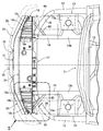
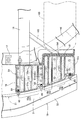
- FIG. 1 is a perspective view of a front part of a vehicle body.
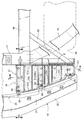
- FIG. 2 is a view in the direction of the arrow 2 in FIG.
- FIG. 3 is a perspective view of the bumper beam.
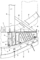
- FIG. 4 is an enlarged view of part 4 of FIG.
- FIG. 5 is an enlarged view of part 5 of FIG.
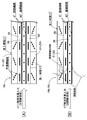
- First embodiment 6 is a cross-sectional view taken along line 6-6 of FIG.
- First embodiment 7 is a cross-sectional view taken along line 7-7 in FIG.
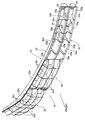
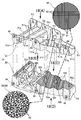
- FIG. 8 is an exploded perspective view of the bumper beam extension.
- FIG. 9 is a view taken in the direction of arrows 9 (A) to 9 (D) in FIG. (First embodiment) FIG.
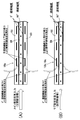
- FIG. 10 is an explanatory diagram of a bumper beam extension manufacturing method.
- FIG. 11 is a diagram for explaining the operation when a collision load is input.
- FIG. 12 is a diagram for explaining the operation when a collision load is input.
- FIG. 13 is a diagram for explaining the operation when a collision load is input.
- FIG. 14 is an explanatory diagram of the operation of the fragile portion of the bumper beam extension.
- FIG. 15 corresponds to FIG.
- FIG. 16 corresponds to FIG.
- FIG. 17 corresponds to FIG. (Third embodiment)
- FIG. 18 is a view taken in the direction of arrows 18 (A) to 18 (D) in FIG. (Third embodiment)
- the front-rear direction impact load input direction
- the left-right direction vehicle width direction
- the up-down direction are defined with reference to the passenger seated in the driver's seat.
- the vehicle body of the embodiment includes a cabin 11 integrally formed in a bathtub shape with FRP such as CFRP (carbon fiber reinforced resin), and a dash panel 12 standing from its front end.
- FRP such as CFRP (carbon fiber reinforced resin)
- a pair of left and right suspension support members 13, 13 that are die-cast with an aluminum alloy are fixed to the front surface.
- the suspension support members 13 and 13 include damper housings 13a and 13a that support upper ends of suspension dampers (not shown), and front side frame rear portions 13b and 13b that are connected to lower portions of the damper housings 13a and 13a and extend forward.
- a pair of left and right front side frame front parts 14, 14 made of an aluminum extruded material or a steel plate press material are connected to the front ends of the front side frame rear parts 13b, 13b.
- a pair of left and right FRP side members 16, 16 are connected to front ends of a pair of left and right FRP upper members 15, 15 extending forward from the left and right upper portions of the dash panel 12.
- a front bulkhead 17 made of FRP formed in a rectangular frame shape in front view is fixed to the front ends of the front side frame front portions 14, 14, and the front ends of the side members 16, 16 are located on the upper left and right sides of the front bulkhead 17.
- a pair of left and right FRP bumper beam extensions 18, 18 are fixed to the front ends of the front side frame front portions 14, 14, and an FRP bumper beam 19 extending in the vehicle width direction at the front ends of the bumper beam extensions 18, 18. Is fixed.
- the front surface of the bumper beam 19 is covered with a bumper face 20.
- An FRP shroud 21 formed in a rectangular frame shape when viewed from the front is disposed at a position surrounded by the front bulkhead 17, the bumper beam 19, and the pair of left and right bumper beam extensions 18, 18.
- cooling system components such as an engine cooling radiator, an air conditioning condenser, and a battery cooling radiator are overlapped and supported in the front-rear direction.
- the bumper beam 19 made of FRP includes a rear main body 31 and front initial load absorbing portions 32.
- the main body 31 includes a pair of U-shaped cross-sections 33, 33 that have an upper wall 33a, a lower wall 33b, and a bottom wall 33c and that open toward the front.
- the upper flange 33d and the lower flange 33e of the upper U-shaped section 33 are overlapped in the front-rear direction and welded together to form a substantially W-shaped section.
- a plurality of vertical ribs 33f that extend in the vertical direction and connect the upper wall 33a, the lower wall 33b, and the bottom wall 33c are separated by a predetermined distance in the longitudinal direction of the bumper beam 19. Formed.
- the upper flange 33d of the upper U-shaped cross section 33 and the lower flange 33e of the lower U-shaped cross section 33 are formed with a plurality of pins 33g projecting forward.
- a plurality of fastening collars 34 are inserted into the bottom wall 33c of the U-shaped cross section 33.
- the initial load absorbing portion 32 is divided into three in the longitudinal direction of the bumper beam 19, and each has substantially the same structure.
- Each initial load absorbing portion 32 includes a flat connecting wall 32a, and a plurality of vertical ribs 32b and a plurality of horizontal ribs 32c formed on the front surface of the connecting wall 32a.
- the vertical ribs 32b extending in the vertical direction and the horizontal ribs 32c extending in the left-right direction intersect with each other in a lattice shape.
- Pin holes 32d, into which the pins 33g of the main body 31 can be fitted, are formed on the upper and lower edges of the connecting wall 32a.
- the initial load absorbing portion 32 is coupled to the main body portion 31 by fitting the pins 33g of the main body portion 31 into the pin holes 32d of the initial load absorbing portion 32 and melting the pins 33g with a vibration tool.
- the bumper beam extension 18 is configured by connecting the upper member 51 and the lower member 52, and the planar shape thereof is a trapezoidal shape or a triangular shape. That is, the inner end in the vehicle width direction of the bumper beam extension 18 extends linearly in the front-rear direction, the inner end (rear end) in the front-rear direction extends linearly in the vehicle width direction, and the outer end (front end) in the front-rear direction extends in the vehicle width direction.
- the outer side is inclined to the inner side in the front-rear direction (rear side). Therefore, the front-rear width of the bumper beam extension 18 is the largest at the inner end in the vehicle width direction and the smallest at the outer end in the vehicle width direction.
- the front end of the bumper beam extension 18 is inclined rearward from the inner side in the vehicle width direction toward the outer side in the vehicle width direction, so that the corners of the vehicle body are rounded to avoid contact with an obstacle in a narrow place. it can. Since the upper member 51 and the lower member 52 of the bumper beam extension 18 have a substantially plane symmetrical structure, the structure will be described below with the upper member 51 as a representative.
- the upper member 51 includes an inner layer portion made of continuous fiber reinforced resin and an outer layer portion made of discontinuous fiber reinforced resin that covers the entire outer surface of the inner layer portion and a part of the inner surface.
- the inner layer portion is displayed in a dark color in FIGS. 8 and 9, and the outer layer portion is displayed in a light color in FIGS. 8 and 9.
- the upper member 51 in which the continuous fiber reinforced resin and the discontinuous fiber reinforced resin are laminated is manufactured as follows.
- a mold 55 for press-molding the upper member 51 of the bumper beam extension 18 includes a female die 56 having a concave cavity 56a for molding the outer surface of the upper member 51, and the upper member 51. Are formed in the cavity 56a and the core 57a, and grooves 56b, 57b,... Are formed in the cavity 56a and the core 57a.
- a first prepreg 58 of discontinuous fiber reinforced resin, a second prepreg 59 of continuous fiber reinforced resin, and a third discontinuous fiber reinforced resin are formed on the cavity 56a of the female mold 56.
- the prepreg 60 is disposed in a preheated state.
- the second prepreg 59 is composed of two layers of carbon fiber continuous fibers UD (sheets of continuous fibers aligned in one direction) laminated in two directions at 0 ° and 90 °, and the first and third prepregs. 58 and 60 are made of carbon fiber discontinuous fiber mats as reinforcements, and are impregnated with a thermoplastic resin (nylon 6, nylon 66, polypropylene, etc.).
- a thermoplastic resin nylon 6, nylon 66, polypropylene, etc.
- the lengths of the discontinuous fibers of the first prepreg 58 and the third prepreg 60 of the discontinuous fiber reinforced resin are 0.9 mm to 100 mm, but about 50 mm is desirable from the viewpoint of impact absorption performance.
- the fiber of each prepreg 58, 59, 60 is preferably glass fiber, and the thermoplastic resin is preferably nylon 6 or nylon 66.
- the male mold 57 When the male mold 57 is lowered with respect to the female mold 56, the second prepreg 59 is pressed by the cavity 56a of the female mold 56 and the core 57a of the male mold 57, and the upper member 51 is molded.
- the first and third prepregs 58 and 60 using the discontinuous fiber as a reinforcing material can be easily deformed, the first prepreg 58 sandwiched between the second prepreg 59 and the cavity 56a of the female die 56 is It flows into the grooves 56b of the cavity 56a, and the ribs and the like on the outer surface of the upper member 51 are simultaneously formed and laminated in a thin film shape along the entire outer surface of the upper member 51.
- the upper member 51 is laminated in a thin film shape along a part of the inner surface of the upper member 51 (part forming a closed cross section). And the upper member 51 is completed by cut
- one continuous fiber 61 is oriented in the front-rear direction, and the other continuous fiber 62 is the vehicle width. Oriented in the direction or up and down direction. Further, the discontinuous fibers 63 of the first and third prepregs 58 and 60 are entangled randomly.
- a continuous fiber reinforced resin having a long fiber UD as a reinforcing material has a relatively high strength. However, since there is a limit to the amount of deformation of the UD, the moldability is low, and it is difficult to mold thin and high ribs. It is. On the other hand, discontinuous fiber reinforced resin having short fibers that are randomly intertwined as a reinforcing material has a relatively low strength, but because the fibers are easily deformed, the moldability is high, and thin and high ribs are formed. Easy to do. Therefore, by laminating the discontinuous fiber reinforced resin on the continuous fiber reinforced resin and molding the upper member 51, the strength and formability of the upper member 51 can be compatible.
- the upper member 51 formed as described above includes a main body 51a extending in the vehicle width direction while being bent into a corrugated plate shape in a substantially trapezoidal or substantially triangular shape in plan view, and upward from the front edge of the main body 51a.
- the second reinforcing ribs 51i that extend in the front-rear direction and connect the front fastening flange 51b and the rear fastening flange 51c on the outer surface of the main body 51a are also discontinuous fiber reinforced resin. Formed with. Further, three nuts 64 are inserted into the front fastening flange 51b of the discontinuous fiber reinforced resin, and three fastening holes 51j are formed in the rear fastening flange 51c of the discontinuous fiber reinforced resin (FIG. 8). reference).
- a slit 51n that extends linearly in the front-rear direction from the vicinity of the front fastening flange 51b to the vicinity of the rear fastening flange 51c is formed in the joint 51e (see FIGS. 5 and 8).
- the lower member 52 has the same shape that is substantially plane-symmetric with the upper member 51 described above, the same subscript as the subscript of each part of the upper member 51 is added to the reference numeral 52 of the lower member 52 so as to overlap. Description is omitted.
- the only difference between the upper member 51 and the lower member 52 is that the lower member 52 includes a plurality of pins 52k that protrude upward from the four joints 52d to 52g, whereas the upper member 51 includes the pins 52k. It is a point provided with a plurality of pin holes 51m which can be fitted (see FIG. 8).
- the main closed cross-section portion 22 of the bumper beam extension 18 is formed by vertically coupling the main impact absorbing portions 18a and 18a having a square cross-sectional shape of the upper member 51 and the lower member 52.
- the first sub-closed cross-section portion 23 and the second sub-closed cross-section portion 24 of the bumper beam extension 18 are composed of a first sub-impact absorbing portion in which the upper member 51 and the lower member 52 form a groove shape having a circular arc cross section.
- 18b, 18b and the second sub-impact absorbers 18c, 18c are connected vertically.
- the main closed cross-section 22 of the bumper beam extension 18 includes a first prepreg 58 of discontinuous fiber reinforced resin, a second prepreg 59 of continuous fiber reinforced resin, and discontinuous fibers.
- the third prepreg 60 made of a reinforced resin has a three-layer structure.
- the first sub-closed cross-section portion 23 and the second sub-closed cross-section portion 24 of the bumper beam extension 18 are formed by disposing the third prepreg 60 made of discontinuous fiber reinforced resin.
- a discontinuous fiber reinforced resin first prepreg 58 and a continuous fiber reinforced resin second prepreg 59 and a laminated two-layer structure are not included.
- the outer surfaces of the upper member 51 and the lower member 52 are all covered with the first prepreg 58 made of discontinuous fiber reinforced resin, and the inner surfaces of the upper member 51 and the lower member 52 are partially made of the continuous fiber reinforced resin.
- the second prepreg 59 is exposed, and the other part is covered with the third prepreg 60 of discontinuous fiber reinforced resin.
- the plate thickness T2 of the first sub-closed section 23 and the second sub-closed section 24 of the two-layer structure is smaller than the plate thickness T1 of the main closed section 22 of the three-layer structure (FIG. 10B )reference).
- the upper member 51 and the lower member 52 having the above-described shapes are configured such that the pins 52k of the lower member 52 are fitted into the pin holes 51m of the upper member 51 so that the joint portions 51d to 51g and 52d to 52g are brought into contact with each other.
- the tips of the pins 52k... Are melted together by a vibrating tool from the upper member 51 side (see FIG. 7).
- the rear fastening flanges 51c and 52c of the upper member 51 and the lower member 52 are linearly aligned in the vertical direction, but the front fastening flanges 51b and 52b of the upper member 51 and the lower member 52 are tilted forward. (See FIG. 6).
- the bumper beam extension 18 in which the upper member 51 and the lower member 52 are coupled to each other includes a rectangular cylindrical main closed cross-sectional portion 22 that is located on the inner side in the vehicle width direction and extends in the front-rear direction, and an elliptic cylindrical shape adjacent to the outer side in the vehicle width direction.
- the first sub closed section 23 and an elliptic cylindrical second sub closed section 24 adjacent to the outside in the vehicle width direction are provided (see FIG. 7).
- the cross-sectional areas of the first and second sub closed cross-section portions 23 and 24 are equal to each other and smaller than the cross-sectional area of the main closed cross-section portion 22.
- the width in the front-rear direction of the substantially triangular bumper beam extension 18 in plan view is gradually narrowed from the inner side to the outer side in the vehicle width direction, so that the main closed cross section 22 is the longest in the front-rear direction, and then The first sub closed section 23 is long and the second sub closed section 24 is the shortest (see FIG. 5).
- the front side frame front portion 14 is disposed behind the first sub impact absorbing portion 18b (first sub closed cross-section portion 23) and the second sub impact absorbing portion 18c (second sub closed cross-section portion 24) of the bumper beam extension 18.
- the front surfaces of the front wheels 65 located on the outer side in the vehicle width direction face each other (see FIGS. 2 and 5).
- a mounting plate 81 made of a metal plate is welded to the front end of the front side frame front portion 14, and a bracing member 82 made of a metal plate is attached to the vehicle width direction outer end of the mounting plate 81 and the vehicle width direction outer surface of the front side frame front portion 14. Are welded. Then, six bolts 83 that pass through the rear fastening flanges 51c and 52c of the bumper beam extension 18 from front to rear are screwed into weld nuts 84 provided on the rear surface of the mounting plate 81, so that the bumper beam extension 18 and the front are fixed. The bulkhead 17 is fastened together with the mounting plate 81.
- bolts 85 penetrating through the fastening collars 34 inserted into the main body 31 of the bumper beam 19 from the front to the rear are screwed into nuts 64 inserted into the front fastening flanges 51 b and 52 b of the bumper beam extension 18.
- the bumper beam 19 is fastened to the front ends of the bumper beam extensions 18 and 18.
- the collision load input from the bumper beam 19 to the bumper beam extension 18 due to the frontal collision of the vehicle is transmitted to the front side frame front part 14 via the mounting plate 81 and the bracing member 82, so that the collision load is transmitted to the front side frame front part. 14 can be efficiently transmitted.
- the bumper beam extension 18 is integrally provided with a main shock absorbing portion 18a and first and second sub shock absorbing portions 18b and 18c which are separated in the vehicle width direction and extend in the front-rear direction, and first and second sub shock absorbing portions. Since the plate thickness T2 of the portions 18b and 18c is smaller than the plate thickness T1 of the main shock absorbing portion 18a, the main shock absorbing portion 18a is a main shock absorbing region having a relatively high shock absorbing capacity, and the first and second sub By making the shock absorbing portions 18b and 18c a sub shock absorbing region having a relatively low shock absorbing capability, the shock absorbing performance of the bumper beam extension 18 is optimized according to the distribution of the magnitude of the input collision load. Can do. Further, by making the bumper beam extension 18 made of FRP, it is lighter than that made of steel plate, and the weight of the first and second sub-impact absorbers 18b, 18c is further reduced by further reducing the thickness. Can do.
- the bumper beam extension 18 is formed by coupling a pair of main impact absorbing portions 18a to form a closed main section 22 and a pair of first and second auxiliary impact absorbing portions 18b and 18c. Since the first and second sub-closed cross-section portions 23 and 24 configured in a cross section are provided, the main impact absorbing portion 18a and the first and second sub-impact absorbing portions 18b and 18c are closed to suppress opening. The shock absorption performance can be improved.
- the main impact absorbing portion 18a is configured by laminating discontinuous fiber reinforced resin layers on both the inner and outer surfaces of the continuous fiber reinforced resin layer, and the first and second sub impact absorbing portions 18b and 18c are formed outside the continuous fiber reinforced resin layer. Since the discontinuous fiber reinforced resin layer is laminated only on the surface, the plate thickness T2 of the first and second secondary shock absorbers 18b and 18c is set smaller than the plate thickness T1 of the main shock absorber 18a. Becomes easier.
- the continuous fiber reinforced resin layer supports the tensile load, and the discontinuous fiber reinforced resin layers on both the inner and outer surfaces support the compressive load.
- the continuous fiber reinforced resin layer suppresses delamination of the continuous fiber reinforced resin layer to enhance the impact absorbing performance, and when the collision load is input to the first and second sub impact absorbing portions 18b and 18c, the continuous fiber reinforced resin layer has a tensile load. Since the discontinuous fiber reinforced resin layer on the outer surface supports the compressive load while supporting the above, delamination of the continuous fiber reinforced resin layer can be suppressed and the shock absorbing performance can be enhanced.
- the second reinforcing ribs 51i, 52i,..., 52i which are made of discontinuous fibers hardened with a thermoplastic resin are formed on the outer surfaces of the main impact absorbing portion 18a and the first and second auxiliary impact absorbing portions 18b, 18c. Are formed in the front-rear direction, so that the second reinforcing ribs 51i... 52i can support the compressive load and thereby more reliably suppress delamination of the continuous fiber reinforced resin layer.
- the first reinforcing ribs 51h... 52h... In which discontinuous fibers are hardened with a thermoplastic resin are formed on the inner surface of 18a in a direction inclined with respect to the front-rear direction. Even if it exists, the delamination of a continuous fiber reinforced resin layer can be suppressed.
- the bumper beam extension 18 includes front fastening flanges 51b and 52b which are bent in a direction crossing the input direction of the collision load and the discontinuous fibers are hardened with a thermoplastic resin. Since the bumper beam 19 is connected to the fastening flanges 51b and 52b, when a collision load is input from the bumper beam 19 to the bumper beam extension 18, the front fastening flanges 51b and 52b having a large pressure receiving area are triggered (triggering to cause destruction). ) And the bumper beam extension 18 is sequentially crushed in the front-rear direction, so that the shock absorbing performance can be enhanced.
- the continuous fibers of the continuous fiber reinforced resin layer of the main impact absorbing portion 18a are oriented in the front-rear direction, which is the input direction of the collision load, and in the vehicle width direction and the up-down direction perpendicular thereto, and have a square cross section.
- 18a is provided with a ridge line that forms a corner along the input direction (front-rear direction) of the collision load (see FIGS. 7 and 8), and is deformed so that the ridge line that forms the corner spreads radially outward by the collision load.
- the continuous fibers oriented in the vehicle width direction and the vertical direction can be stretched to increase the amount of shock absorption.
- first and second sub closed cross-section portions 23 and 24 are continuously provided on the outer side in the vehicle width direction of the main closed cross-section portion 22, and the main closed cross-section portion 22 is linearly formed at the front-rear direction outer end of the front side frame front portion 14. Since the first and second sub closed cross-section portions 23 and 24 are connected to the side surface of the front side frame front portion 14 via the brace member 82 (see FIG. 5), the front-rear direction dimension of the front portion of the vehicle body is reduced. It is possible not only to secure impact absorption performance while reducing the load, but also to efficiently absorb the collision load at the time of offset collision.
- the collision load of the frontal collision is first the front end of the main closed cross-section portion 22.
- the bumper beam extension 18 can be sequentially crushed in the front-rear direction as a trigger for crushing to improve the shock absorbing performance.
- the bumper beam extension 18 when a collision load is intensively input to the end in the vehicle width direction of the bumper beam 19 due to a narrow offset frontal collision, the bumper beam extension 18 has a trapezoidal shape or a triangular shape whose width in the front-rear direction is smaller toward the outer side in the vehicle width direction.
- the main impact absorbing portion 18a formed on the inner side in the vehicle width direction is aligned in the front-rear direction with respect to the front side frame front portion 14, and the first and second auxiliary impact absorbing portions 18b, 18c on the outer side in the vehicle width direction are front wheels. Since the first and second auxiliary impact absorbing portions 18b and 18c come into contact with the front wheel 65 due to a collision load, the bumper beam extension 18 moves backward without tilting.
- the collision load input from the bumper beam 19 is reliably supported by the front side frame front portion 14 to effectively crush the main impact absorbing portion 18a of the bumper beam extension 18, and the collision load is supported by the front wheel 65.
- the impact absorbing effect can be enhanced.
- the first and second auxiliary impact absorbing portions 18b and 18c smaller than the main impact absorbing portion 18a are juxtaposed in the vehicle width direction, the first and second auxiliary impact absorbing portions 18b and 18c are curved in the vehicle width direction.
- the front wheel 65 can be brought into contact with the entire peripheral surface to exert the maximum shock absorbing performance.
- the first and second sub-impact absorbing portions 18b and 18c include a plurality of second reinforcing ribs 51i, 52i, which are formed of discontinuous fiber reinforced resin layers and extend in the front-rear direction, the contact area with the front wheel 65 Can increase the shock absorbing performance.
- the bumper beam extension 18 includes slits 51n and 52n that extend in the front-rear direction and can be easily broken between the main shock absorbing portion 18a and the first and second sub shock absorbing portions 18b and 18c.
- the first and second sub-impact absorbers 18b and 18c separated from the main impact absorber 18a by breaking 51n and 52n are brought into contact with the front wheel 65 at an early stage (see FIG. 14), and the main impact absorber 18a and the first
- the shock absorption performance can be further enhanced by crushing both of the second sub shock absorbing portions 18b and 18c independently.
- the rear end of the bumper beam extension 18 of the first embodiment extends linearly in the vehicle width direction
- the rear end of the bumper beam extension 18 of the second embodiment is located at a portion facing the front wheel 65.
- An extension 18d that protrudes rearward is provided.
- the left and right ends of the front bulkhead 17 and the mounting plate 81 are also bent in a crank shape.
- the bumper beam extension 18d By forming the extension 18d in the bumper beam extension 18, the distance between the rear end of the bumper beam extension 18 and the front end of the front wheel 65 is reduced, and the bumper beam extension 18 is immediately attached when a collision load of frontal collision is input.
- the bumper beam extension 18 can be further improved in impact absorbing performance by preventing it from inclining by being brought into contact with the front wheel 65.
- the axis of the main impact absorbing portion 18a that is, the axis of the main closed section 22 is aligned in the front-rear direction, but the axis of the first sub impact absorbing portion 18b and the second sub impact absorbing portion 18c, That is, the axes of the first sub closed cross-section portion 23 and the second sub closed cross-section portion 24 are inclined so that the front side faces the outside in the vehicle width direction.
- the two second reinforcing ribs 51i and 51i on the outer surface of the main shock absorbing portion 18a extend in parallel with the axis of the main shock absorbing portion 18a, and the outer surfaces of the first sub shock absorbing portion 18b and the second sub shock absorbing portion 18c.
- the two second reinforcing ribs 51i and 51i extend in parallel with the axes of the first sub impact absorbing portion 18b and the second sub impact absorbing portion 18c.
- the main shock absorber 18a (main closed section 22) having the front-rear axis. Can be crushed in the axial direction to exhibit effective shock absorbing performance.
- the first sub-impact absorber 18b and the second sub-impact absorber 18c (first sub-closure) having an oblique axis.
- the cross-sectional portion 23 and the second sub-closed cross-sectional portion 24) can be crushed in the axial direction to exhibit effective shock absorbing performance.
- the collision load of the frontal collision is transmitted from the main shock absorbing portion 18a of the bumper beam extension 18 to the front end of the front side frame front portion 14 linearly connected to the rear thereof, and the collision load of the oblique collision is transmitted to the bumper beam extension 18.
- the bumper beam extension 18 can be reliably crushed without tilting.
- the bumper beam extension and bumper beam of the present invention are not limited to those on the front side of the automobile, but may be those on the rear side.
- vehicle body frame of the present invention is not limited to the front side frame front portion 14 of the embodiment, and may be a frame arranged in the front-rear direction at the vehicle body front portion or the vehicle body rear portion.
- the FRP of the present invention is not limited to the CFRP (carbon fiber reinforced resin) of the embodiment, and may be other types of FRP such as glass fiber reinforced resin and aramid fiber reinforced resin.
- each bumper beam extension 18 is not limited to two in the embodiment, and may be one or three or more.
- the fragile portion of the present invention is not limited to the slits 51n and 52n of the embodiment, and may be a thin portion where the thickness of the bumper beam extension 18 is locally thinned.
Abstract
バンパービームエクステンション(18)は平面視で台形状であり、車幅方向内側の主衝撃吸収部(18a)と、車幅方向外側の副衝撃吸収部(18b,18c)とを備え、主衝撃吸収部(18a)は車体フレーム(14)に対して前後方向に整列するとともに、副衝撃吸収部(18b,18c)は車輪(65)に対して前方に配置されるので、ナローオフセット衝突時にバンパービーム(19)の車幅方向外端側に衝突荷重が入力した場合であっても、副衝撃吸収部(18a,18b)が車輪(65)に当接することでバンパービームエクステンション(18)は傾くことなく前後方向に移動する。これにより、バンパービーム(19)から入力する衝突荷重で主衝撃吸収部(18a)および副衝撃吸収部(18b,18c)の両方を効果的に圧壊して衝撃吸収効果を高めることができる。
Description
本発明は、前後方向に延びる車体フレームと車幅方向に延びるバンパービームとの間にFRP製のバンパービームエクステンションを配置した自動車の車体構造に関する。
バンパリインフォース(バンパービーム)の車幅方向外端からリインフォースエクステンション(バンパービームエクステンション)を後方に延ばし、ナローオフセット衝突の衝突荷重で車幅方向内向きに折れ曲がったリインフォースエクステンションの後端の凸部をフロントサイドメンバ(フロントサイドフレーム)の車幅方向外側面に当接させることで、衝突荷重をリインフォースエクステンションからフロントサイドメンバに伝達して支持し、リインフォースエクステンションの曲げ変形および軸方向圧壊により衝突エネルギーを吸収するものが、下記特許文献1により公知である。
日本特開2008-213739公報
しかしながら、上記特許文献1に記載されたものは、バンパリインフォースと前輪との間の距離が小さいためにリインフォースエクステンションの前後方向寸法を大きく確保することができない場合、ナローオフセット衝突の衝突荷重が入力してもリインフォースエクステンションが車幅方向内向きに充分に折れ曲がらず、その凸部がフロントサイドメンバの車幅方向外側面に当接することができないため、必要な衝撃吸収性能が得られない可能性があった。
本発明は前述の事情に鑑みてなされたもので、オフセット衝突時におけるバンパービームエクステンションの衝撃吸収性能を高めることを目的とする。
上記目的を達成するために、本発明によれば、前後方向に延びる車体フレームと車幅方向に延びるバンパービームとの間にFRP製のバンパービームエクステンションを配置した自動車の車体構造であって、前記バンパービームエクステンションの平面視形状は、前後方向内端が車幅方向と平行であり、車幅方向内端が前後方向と平行であり、かつ前後方向外端が車幅方向外側ほど前後方向内側に傾斜する台形状ないしは三角形状であり、前記バンパービームエクステンションは車幅方向内側の主衝撃吸収部と、車幅方向外側の副衝撃吸収部とを備え、前記主衝撃吸収部は車体フレームに対して前後方向に整列するとともに、前記副衝撃吸収部は車輪に対して前方に配置されることを第1の特徴とする自動車の車体構造が提案される。
また本発明によれば、前記第1の特徴に加えて、前記副衝撃吸収部および前記車輪は前後方向に整列して配置されることを第2の特徴とする自動車の車体構造が提案される。
また本発明によれば、前記第1または第2の特徴に加えて、前記バンパービームエクステンションに、前記主衝撃吸収部よりも小さい複数の前記副衝撃吸収部を車幅方向に並置したことを第3の特徴とする自動車の車体構造が提案される。
また本発明によれば、前記第1~第3の何れか1つの特徴に加えて、前記バンパービームエクステンションは連続繊維強化樹脂層の少なくとも外表面に不連続繊維強化樹脂層を積層して構成され、前記副衝撃吸収部の前記不連続繊維強化樹脂層は前後方向に延びる複数のリブを備えることを第4の特徴とする自動車の車体構造が提案される。
また本発明によれば、前記第1~第4の何れか1つの特徴に加えて、前記バンパービームエクステンションは、一対の前記主衝撃吸収部を結合して閉断面に構成した主閉断面部と、一対の前記副衝撃吸収部を結合して閉断面に構成した副閉断面部とを備えることを第5の特徴とする自動車の車体構造が提案される。
また本発明によれば、前記第1~第5の何れか1つの特徴に加えて、前記バンパービームエクステンションは前記主衝撃吸収部と前記副衝撃吸収部との間に脆弱部を備えることを第6の特徴とする自動車の車体構造が提案される。
また本発明によれば、前記第6の特徴に加えて、前記脆弱部は前後方向に延びるスリットであることを第7の特徴とする自動車の車体構造が提案される。
また本発明によれば、前記第1~第7の何れか1つの特徴に加えて、前記バンパービームエクステンションの前記副衝撃吸収部の前後方向内端から前記車輪に向けて延長部を突設したことを第8の特徴とする自動車の車体構造が提案される。
また本発明によれば、前記第1の特徴に加えて、前記副衝撃吸収部は前後方向外側が車幅方向外側に傾斜するように配置されることを第9の特徴とする自動車の車体構造が提案される。
また本発明によれば、前記第9の特徴に加えて、前記バンパービームエクステンションの前後方向外端は、車幅方向内側から車幅方向外側に向かって前後方向内側に傾斜することを第10の特徴とする自動車の車体構造が提案される。
また本発明によれば、前記第9または第10の特徴に加えて、前記バンパービームエクステンションの車幅方向に延びる前後方向内端は前記車体フレームの前後方向外端に取付プレートを介して取り付けられ、前記主衝撃吸収部は前記車体フレームの前後方向外端に直線状に接続され、前記副衝撃吸収部は前記車体フレームの側面に筋交い部材を介して接続されることを第11の特徴とする自動車の車体構造が提案される。
また本発明によれば、前記第9~第11の何れか1つの特徴に加えて、前記バンパービームエクステンションは上部部材および下部部材を結合して構成され、前記上部部材および前記下部部材は、前後方向に配向された連続繊維と車幅方向ないし上下方向に配向された連続繊維とを樹脂で固めた内層と、不連続繊維を樹脂で固めた外層とを備えることを第12の特徴とする自動車の車体構造が提案される。
また本発明によれば、前記第12の特徴に加えて、前記外層は前記主衝撃吸収部および前記副衝撃吸収部の軸線に沿って延びるリブを備えることを第13の特徴とする自動車の車体構造が提案される。
また本発明によれば、前記第12または第13の特徴に加えて、前記外層は前記バンパービームエクステンションの衝突荷重の入力方向に対して交差する方向に折り曲げられたフランジを備えることを第14の特徴とする自動車の車体構造が提案される。
また本発明によれば、前記第9~第14の何れか1つの特徴に加えて、前記バンパービームエクステンションは、一対の前記主衝撃吸収部を結合して閉断面に構成した主閉断面部と、一対の前記副衝撃吸収部を結合して閉断面に構成した副閉断面部とを備えることを第15の特徴とする自動車の車体構造が提案される。
また本発明によれば、前記第1の特徴に加えて、前記副衝撃吸収部の板厚を前記主衝撃吸収部の板厚よりも小さく設定したことを第16の特徴とする自動車の車体構造が提案される。
また本発明によれば、前記第16の特徴に加えて、前記バンパービームエクステンションは、一対の前記主衝撃吸収部を結合して閉断面に構成した主閉断面部と、一対の前記副衝撃吸収部を結合して閉断面に構成した副閉断面部とを備えることを第17の特徴とする自動車の車体構造が提案される。
また本発明によれば、前記第16または第17の特徴に加えて、前記主衝撃吸収部は連続繊維強化樹脂層の内外両表面に不連続繊維強化樹脂層を積層して構成され、前記副衝撃吸収部は連続繊維強化樹脂層の外表面だけに不連続繊維強化樹脂層を積層して構成されることを第18の特徴とする自動車の車体構造が提案される。
また本発明によれば、前記第16~第18の何れか1つの特徴に加えて、前記主衝撃吸収部および前記副衝撃吸収部の外表面には不連続繊維を熱可塑性樹脂で固めたリブが前後方向に形成され、前記主衝撃吸収部の内表面には不連続繊維を熱可塑性樹脂で固めたリブが前後方向に対して傾斜する方向に形成されることを第19の特徴とする自動車の車体構造が提案される。
また本発明によれば、前記第16~第19の何れか1つの特徴に加えて、前記バンパービームエクステンションは衝突荷重の入力方向に対して交差する方向に折り曲げられて不連続繊維を熱可塑性樹脂で固めたフランジを備え、前記フランジに前記バンパービームが接続されることを第20の特徴とする自動車の車体構造が提案される。
また本発明によれば、前記第18の特徴に加えて、前記主衝撃吸収部の連続繊維強化樹脂層の連続繊維は、衝突荷重の入力方向である第1の方向と、それに直交する第2の方向とに配向され、かつ前記主衝撃吸収部は衝突荷重の入力方向に沿う角部を構成する稜線を備えることを第21の特徴とする自動車の車体構造が提案される。
また本発明によれば、前記第17の特徴に加えて、前記副閉断面部は前記主閉断面部の車幅方向外側に連設され、前記主閉断面部は前記車体フレームの前後方向外端に直線状に接続され、前記副閉断面部は前記車体フレームの側面に筋交い部材を介して接続されることを第22の特徴とする自動車の車体構造が提案される。
また本発明によれば、前記第22の特徴に加えて、前記副閉断面部の前後方向外端は前記主閉断面部の前後方向外端よりも前後方向内側に位置することを第23の特徴とする自動車の車体構造が提案される。
尚、実施の形態のフロントサイドフレーム前部14は本発明の車体フレームに対応し、実施の形態の第1副衝撃吸収部18bおよび第2副衝撃吸収部18cは本発明の副衝撃吸収部に対応し、実施の形態の第1副閉断面部23および第2副閉断面部24は本発明の副閉断面部に対応し、実施の形態の前部締結フランジ51b,51bは本発明のフランジに対応し、実施の形態の第1補強リブ51h,52hおよび第2補強リブ51i,52iは本発明のリブに対応し、実施の形態のスリット51n,52nは本発明の脆弱部に対応し、実施の形態の前輪65は本発明の車輪に対応する。
本発明の第1の特徴によれば、車体フレームとバンパービームとの間に配置されるバンパービームエクステンションはFRP材で構成され、バンパービームエクステンションの平面視形状は、前後方向内端が車幅方向と平行であり、車幅方向内端が前後方向と平行であり、かつ前後方向外端が車幅方向外側ほど前後方向内側に傾斜する台形状ないしは三角形状である。バンパービームエクステンションは車幅方向内側の主衝撃吸収部と、車幅方向外側の副衝撃吸収部とを備え、主衝撃吸収部は車体フレームに対して前後方向に整列するとともに、副衝撃吸収部は車輪に対して前方に配置されるので、ナローオフセット前面衝突時やナローオフセット後面衝突時にバンパービームの車幅方向外端側に衝突荷重が入力した場合であっても、副衝撃吸収部が車輪に当接することでバンパービームエクステンションは傾くことなく前後方向に移動する。これにより、バンパービームから入力する衝突荷重を車体フレームで確実に支持してバンパービームエクステンションの主衝撃吸収部を効果的に圧壊するとともに、前記衝突荷重を車輪で支持してバンパービームエクステンションの副衝撃吸収部を効果的に圧壊することで、バンパービームエクステンションによる衝撃吸収効果を高めることができる。
また本発明の第2の特徴によれば、副衝撃吸収部および車輪は前後方向に整列して配置されるので、副衝撃吸収部を一層確実に車輪に当接させることができる。
また本発明の第3の特徴によれば、バンパービームエクステンションに、主衝撃吸収部よりも小さい複数の副衝撃吸収部を車幅方向に並置したので、複数の副衝撃吸収部を車幅方向に湾曲した車輪の周面全体に当接させて最大限の衝撃吸収性能を発揮させることができる。
また本発明の第4の特徴によれば、バンパービームエクステンションは連続繊維強化樹脂層の少なくとも外表面に不連続繊維強化樹脂層を積層して構成され、副衝撃吸収部の前記不連続繊維強化樹脂層は前後方向に延びる複数のリブを備えるので、バンパービームエクステンションの剛性を連続繊維強化樹脂層で確保しながら、成形性の良い不連続繊維強化樹脂層でリブを容易に成形することができ、しかもリブにより車輪との当接面積を増加させて衝撃吸収性能を高めることができる。
また本発明の第5の特徴によれば、バンパービームエクステンションは、一対の主衝撃吸収部を結合して閉断面に構成した主閉断面部と、一対の副衝撃吸収部を結合して閉断面に構成した副閉断面部とを備えるので、主衝撃吸収部および副衝撃吸収部を閉断面化して口開きを抑制することで衝撃吸収性能を高めることができる。
また本発明の第6の特徴によれば、バンパービームエクステンションは主衝撃吸収部と副衝撃吸収部との間に脆弱部を備えるので、脆弱部の破断により主衝撃吸収部から分離した副衝撃吸収部を早期に車輪に当接させ、主衝撃吸収部および副衝撃吸収部の両方を独立して圧壊することで衝撃吸収性能を更に高めることができる。
また本発明の第7の特徴によれば、脆弱部は前後方向に延びるスリットであるので、スリットを確実に破断して主衝撃吸収部から副衝撃吸収部を分離することができる。
また本発明の第8の特徴によれば、バンパービームエクステンションの副衝撃吸収部の前後方向内端から車輪に向けて延長部を突設したので、副衝撃吸収部を早期に車輪に当接させて副衝撃吸収部の衝撃吸収量を増加させることができる。
また本発明の第9の特徴によれば、副衝撃吸収部は前後方向外側が車幅方向外側に傾斜するように配置されるので、斜め衝突の衝突荷重を副衝撃吸収部の軸線方向に受け止めて充分な衝撃吸収部性能を発揮させることができる。
また本発明の第10の特徴によれば、バンパービームエクステンションの前後方向外端は、車幅方向内側から車幅方向外側に向かって前後方向内側に傾斜するので、車体の隅部に丸みを持たせて狭い場所での障害物との接触を回避することができる。
また本発明の第11の特徴によれば、バンパービームエクステンションの車幅方向に延びる前後方向内端は車体フレームの前後方向外端に取付プレートを介して取り付けられ、主衝撃吸収部は車体フレームの前後方向外端に直線状に接続され、副衝撃吸収部は車体フレームの側面に筋交い部材を介して接続されるので、前面衝突あるいは後面衝突の衝突荷重をバンパービームエクステンションの主衝撃吸収部を介して車体フレームに伝達し、斜め衝突の荷重をバンパービームエクステンションの副衝撃吸収部および筋交い部材を介して車体フレームに伝達することで、種々の方向の衝突荷重に対して有効な衝撃吸収性能を発揮させることができる。
また本発明の第12の特徴によれば、バンパービームエクステンションは上部部材および下部部材を結合して構成され、上部部材および下部部材は、前後方向に配向された連続繊維と車幅方向ないし上下方向に配向された連続繊維とを樹脂で固めた内層と、不連続繊維を樹脂で固めた外層とを備えるので、軸線の方向が異なる主衝撃吸収部および副衝撃吸収部を一体に備える上部部材および下部部材を容易に成形することが可能であるだけでなく、高強度の内層および低強度の外層を積層することで、衝突荷重が入力した端部側から繊維および樹脂が逐次破断することで衝撃吸収量を増加させることができる。
また本発明の第13の特徴によれば、外層は主衝撃吸収部および副衝撃吸収部の軸線に沿って延びるリブを備えるので、成形性の高い不連続繊維でリブを容易に成形できるだけでなく、リブで内層の連続繊維の層間剥離を抑制して衝撃吸収性能を高めることができる。
また本発明の第14の特徴によれば、外層はバンパービームエクステンションの衝突荷重の入力方向に対して交差する方向に折り曲げられたフランジを備えるので、バンパービームからバンパービームエクステンションに衝突荷重が入力したときに、受圧面積が大きいフランジがトリガ(破壊を引き起こすきっかけ)となってバンパービームエクステンションが前後方向に順次圧壊することで衝撃吸収性能を高めることができる。
また本発明の第15の特徴によれば、バンパービームエクステンションは、一対の前記主衝撃吸収部を結合して閉断面に構成した主閉断面部と、一対の前記副衝撃吸収部を結合して閉断面に構成した副閉断面部とを備えるので、主衝撃吸収部および副衝撃吸収部を閉断面化して口開きを抑制することで衝撃吸収性能を高めることができる。
また本発明の第16の特徴によれば、副衝撃吸収部の板厚を主衝撃吸収部の板厚よりも小さく設定したので、主衝撃吸収部を衝撃吸収能力が比較的に高いメインの衝撃吸収領域とし、副衝撃吸収部を衝撃吸収能力が比較的に低いサブの衝撃吸収領域とすることで、入力する衝突荷重の大きさの分布に応じてバンパービームエクステンションの衝撃吸収性能を最適化することができる。またバンパービームエクステンションをFRP製としたことで鋼板製のものよりも軽量になり、しかも副衝撃吸収部の板厚を小さくした分だけ更なる軽量化を図ることができる。
また本発明の第17の特徴によれば、バンパービームエクステンションは、一対の主衝撃吸収部を結合して閉断面に構成した主閉断面部と、一対の副衝撃吸収部を結合して閉断面に構成した副閉断面部とを備えるので、主衝撃吸収部および副衝撃吸収部を閉断面化して口開きを抑制することで衝撃吸収性能を高めることができる。
また本発明の第18の特徴によれば、主衝撃吸収部は連続繊維強化樹脂層の内外両表面に不連続繊維強化樹脂層を積層して構成され、副衝撃吸収部は連続繊維強化樹脂層の外表面だけに不連続繊維強化樹脂層を積層して構成されるので、副衝撃吸収部の板厚を主衝撃吸収部の板厚よりも小さく設定することが容易になる。しかも主衝撃吸収部に衝突荷重が入力したときに、連続繊維強化樹脂層が引張荷重を支持して内外両表面の不連続繊維強化樹脂層が圧縮荷重を支持することで、連続繊維強化樹脂層の層間剥離を抑制して衝撃吸収性能を高めるとともに、副衝撃吸収部に衝突荷重が入力したときに、連続繊維強化樹脂層が引張荷重を支持して外表面の不連続繊維強化樹脂層が圧縮荷重を支持することで、連続繊維強化樹脂層の層間剥離を抑制して衝撃吸収性能を高めることができる。
また本発明の第19の特徴によれば、主衝撃吸収部および副衝撃吸収部の外表面には不連続繊維を熱可塑性樹脂で固めたリブが前後方向に形成されるので、リブが圧縮荷重を支持することで連続繊維強化樹脂層の層間剥離を一層確実に抑制することができるだけでなく、主衝撃吸収部の内表面には不連続繊維を熱可塑性樹脂で固めたリブが前後方向に対して傾斜する方向に形成されるので、斜め衝突の衝突荷重が入力した場合であっても連続繊維強化樹脂層の層間剥離を抑制することができる。
また本発明の第20の特徴によれば、バンパービームエクステンションは衝突荷重の入力方向に対して交差する方向に折り曲げられて不連続繊維を熱可塑性樹脂で固めたフランジを備え、フランジにバンパービームが接続されるので、バンパービームからバンパービームエクステンションに衝突荷重が入力したときに、受圧面積が大きいフランジがトリガ(破壊を引き起こすきっかけ)となってバンパービームエクステンションが前後方向に順次圧壊することで衝撃吸収性能を高めることができる。
また本発明の第21の特徴によれば、主衝撃吸収部の連続繊維強化樹脂層の連続繊維は、衝突荷重の入力方向である第1の方向と、それに直交する第2の方向とに配向され、かつ主衝撃吸収部は衝突荷重の入力方向に沿う角部を構成する稜線を備えるので、衝突荷重によって角部を構成する稜線が径方向外側に広がるように変形するとき、第2の方向に配向された連続繊維が伸びて衝撃吸収量を増大することができる。
また本発明の第22の特徴によれば、副閉断面部は主閉断面部の車幅方向外側に連設され、主閉断面部は車体フレームの前後方向外端に直線状に接続され、副閉断面部は車体フレームの側面に筋交い部材を介して接続されるので、車体前部の前後方向寸法を小型化しながら衝撃吸収性能を確保することができるだけでなく、オフセット衝突時の衝突荷重を効率的に吸収することができる。
また本発明の第23の特徴によれば、副閉断面部の前後方向外端は主閉断面部の前後方向外端よりも前後方向内側に位置するので、前面衝突あるいは後面衝突の衝突荷重は先ず主閉断面部の前後方向外端に入力し、そこが圧壊のトリガになってバンパービームエクステンションを前後方向に順次圧壊して衝撃吸収性能を高めることができる。
14 フロントサイドフレーム前部(車体フレーム)
18 バンパービームエクステンション
18a 主衝撃吸収部
18b 第1副衝撃吸収部(副衝撃吸収部)
18c 第2副衝撃吸収部(副衝撃吸収部)
18d 延長部
19 バンパービーム
22 主閉断面部
23 第1副閉断面部(副閉断面部)
24 第2副閉断面部(副閉断面部)
51 上部部材
51b 前部締結フランジ(フランジ)
51h 第1補強リブ(リブ)
51i 第2補強リブ(リブ)
51n スリット(脆弱部)
52 下部部材
52b 前部締結フランジ(フランジ)
52h 第1補強リブ(リブ)
52i 第2補強リブ(リブ)
52n スリット(脆弱部)
65 前輪(車輪)
81 取付プレート
82 筋交い部材
以下、図1~図14に基づいて本発明の第1の実施の形態を説明する。尚、本明細書において、前後方向(衝突荷重の入力方向)、左右方向(車幅方向)および上下方向とは、運転席に着座した乗員を基準として定義される。
図1および図2に示すように、実施の形態の自動車の車体はCFRP(カーボン繊維強化樹脂)等のFRPでバスタブ状に一体成形したキャビン11を備えており、その前端から起立するダッシュパネル12の前面にアルミニウム合金でダイキャスト成形した左右一対のサスペンション支持部材13,13が固定される。サスペンション支持部材13,13は、図示せぬサスペンションダンパーの上端を支持するダンパーハウジング13a,13aと、ダンパーハウジング13a,13aの下部に接続されて前方に延びるフロントサイドフレーム後部13b,13bとを備えており、フロントサイドフレーム後部13b,13bの前端にアルミニウム押し出し材あるいは鋼板プレス材で構成された左右一対のフロントサイドフレーム前部14,14が接続される。ダッシュパネル12の左右上部から前方に延びる左右一対のFRP製のアッパーメンバ15,15の前端に左右一対のFRP製のサイドメンバ16,16が接続される。
フロントサイドフレーム前部14,14の前端に正面視で矩形枠状に形成されたFRP製のフロントバルクヘッド17が固定されており、フロントバルクヘッド17の左右上部にサイドメンバ16,16の前端が接続される。フロントサイドフレーム前部14,14の前端に左右一対のFRP製のバンパービームエクステンション18,18が固定されており、そのバンパービームエクステンション18,18の前端に車幅方向に延びるFRP製のバンパービーム19が固定される。バンパービーム19の前面はバンパーフェイス20で覆われる。フロントバルクヘッド17、バンパービーム19および左右一対のバンパービームエクステンション18,18に囲まれた位置に、正面視で矩形枠状に形成されたFRP製のシュラウド21が配置されており、シュラウド21の内部にエンジン冷却用ラジエータ、空調用コンデンサ、バッテリ冷却用ラジエータ等の冷却系部品(不図示)が前後方向に重ね合わされて支持される。
次に、図3および図6に基づいてバンパービーム19の構造を説明する。
FRP製のバンパービーム19は、後側の本体部31と前側の初期荷重吸収部32…とを備える。本体部31は上壁33a、下壁33bおよび底壁33cを有して前方に向けて開放する一対のU字状断面部33,33を備えており、下側のU字状断面部33の上部フランジ33dと上側のU字状断面部33の下部フランジ33eとが前後方向に重ね合わされて一体に溶着され、略W字状断面を形成する。U字状断面部33の内部には、鉛直方向に延びて上壁33a、下壁33bおよび底壁33cを接続する複数の縦リブ33f…が、バンパービーム19の長手方向に所定距離だけ離間して形成される。上側のU字状断面部33の上部フランジ33dと、下側のU字状断面部33の下部フランジ33eとには、前方に向かって突出する複数のピン33g…が形成される。またU字状断面部33の底壁33cには、複数の締結カラー34…がインサートされる。
初期荷重吸収部32…はバンパービーム19の長手方向に3分割されており、各々が実質的に同じ構造を有している。各初期荷重吸収部32は、平坦な連結壁32aと、連結壁32aの前面に形成された複数の縦リブ32b…および複数の横リブ32c…とを備える。上下方向に延びる縦リブ32b…と左右方向に延びる横リブ32c…とは相互に格子状に交差する。連結壁32aの上縁および下縁には本体部31のピン33g…が嵌合可能なピン孔32d…が形成される。初期荷重吸収部32のピン孔32d…に本体部31のピン33g…を嵌合し、そのピン33g…を振動工具で溶融することで、本体部31に初期荷重吸収部32が結合される。
次に、図4~図10に基づいて、バンパービームエクステンション18の構造を説明する。
バンパービームエクステンション18は上部部材51および下部部材52を結合して構成されるもので、その平面形状は台形状ないしは三角形状である。即ち、バンパービームエクステンション18の車幅方向内端は前後方向に直線状に延び、前後方向内端(後端)は車幅方向に直線状に延び、前後方向外端(前端)は車幅方向外側ほど前後方向内側(後側)に向かうように傾斜している。よってバンパービームエクステンション18の前後方向幅は、車幅方向内端で最も大きくなり、車幅方向外端で最も小さくなる。バンパービームエクステンション18の前端が車幅方向内側から車幅方向外側に向かって後方に傾斜することで、車体の隅部に丸みを持たせて狭い場所での障害物との接触を回避することができる。バンパービームエクステンション18の上部部材51および下部部材52は略面対称な構造であるため、以下、上部部材51を代表として構造を説明する。
上部部材51は連続繊維強化樹脂製の内層部と、内層部の外表面の全面および内表面の一部を覆う不連続繊維強化樹脂製の外層部とで構成される。内層部は図8および図9において濃色で表示され、外層部は図8および図9において淡色で表示される。
連続繊維強化樹脂および不連続繊維強化樹脂を積層した上部部材51は、以下のようにして製造される。図10(A)に示すように、バンパービームエクステンション18の上部部材51をプレス成形する金型55は、上部部材51の外表面を成形する凹状のキャビティ56aを有する雌型56と、上部部材51の内表面を成形する凸状のコア57aを有する雄型57とからなり、キャビティ56aおよびコア57aにはリブ等を成形する溝56b…,57b…が形成される。金型55を型開きした状態で、雌型56のキャビティ56aの上部に不連続繊維強化樹脂の第1プリプレグ58と、連続繊維強化樹脂の第2プリプレグ59と、不連続繊維強化樹脂の第3プリプレグ60とが予備加熱した状態で配置される。
第2プリプレグ59はカーボンファイバーの連続繊維のUD(連続繊維を一方向に引き揃えたシート)を0°および90°の方向に2層に積層したものを補強材とし、第1、第3プリプレグ58,60はカーボンファイバーの不連続繊維のマットを補強材とするもので、それらに熱可塑性樹脂(ナイロン6、ナイロン66、ポリプロピレン等)が含浸される。予備加熱した複数枚のプリプレグを積層状態で金型内に挿入して加圧成形し、その後に冷却すると繊維強化樹脂製品が得られる。
不連続繊維強化樹脂の第1プリプレグ58および第3プリプレグ60の不連続繊維の長さは0.9mm~100mmであるが、衝撃吸収性能の観点からは50mm前後が望ましい。コストおよび衝撃吸収性能を両立させるためには、各プリプレグ58,59,60の繊維はグラスファイバーが好ましく、熱可塑性樹脂はナイロン6あるいはナイロン66が望ましい。
雌型56に対して雄型57を下降させると、第2プリプレグ59が雌型56のキャビティ56aと雄型57のコア57aとによってプレスされ、上部部材51が成形される。このとき、不連続繊維を補強材とする第1、第3プリプレグ58,60は容易に変形可能であるため、第2プリプレグ59と雌型56のキャビティ56aとによって挟まれた第1プリプレグ58はキャビティ56aの溝56b…内に流入し、上部部材51の外表面のリブ等を同時に成形するとともに、上部部材51の外表面の全面に沿って薄い膜状に積層される。同様に、第2プリプレグ59と雄型57のコア57aとによって挟まれた第3プリプレグ60はコア57aの溝57b…内に流入し、上部部材51の内表面のリブ等を同時に成形するとともに、上部部材51の内表面の一部(閉断面を形成する部分)に沿って薄い膜状に積層される。そして金型55から取り出した製品の外周の余剰部分を切断することで、上部部材51を完成する。
図8の円内に拡大して示すように、第2プリプレグ59の連続繊維61…,62…のうち、一方の連続繊維61…は前後方向に配向され、他方の連続繊維62…は車幅方向ないし上下方向に配向される。また第1、第3プリプレグ58,60の不連続繊維63…はランダムに絡みあっている。
長い繊維のUDを補強材として有する連続繊維強化樹脂は比較的に強度が高くなるが、UDの変形量に限界があるために成形性は低くなり、細くて高いリブ等を成形するのが困難である。一方、ランダムに絡み合った短い繊維を補強材として有する不連続繊維強化樹脂は比較的に強度が低くなるが、繊維が容易に変形するために成形性は高くなり、細くて高いリブ等を成形するのが容易である。よって、連続繊維強化樹脂に不連続繊維強化樹脂を積層して上部部材51を成形することで、上部部材51の強度および成形性を両立させることができる。
上述のようにして成形された上部部材51は、平面視で略台形状ないしは略三角形状で波板状に屈曲しながら車幅方向に延びる本体部51aと、本体部51aの前縁から上方に折れ曲がる前部締結フランジ51bと、本体部51aの後縁から上方に折れ曲がる後部締結フランジ51cと、本体部51aの内面の車幅方向に離間した位置を前後方向に延びる4個の接合部51d~51gとを備える。二つの接合部51d,51e間の内面には60°間隔で3方向に交差する第1補強リブ51h…が前後方向に少なくとも二つ不連続繊維強化樹脂で形成され(図8の第1補強リブ52hと同じ形状・配置)、本体部51aの外表面には前後方向に延びて前部締結フランジ51bおよび後部締結フランジ51cを接続する6本の第2補強リブ51i…が同じく不連続繊維強化樹脂で形成される。また不連続繊維強化樹脂の前部締結フランジ51bには3個のナット64…がインサートされ、不連続繊維強化樹脂の後部締結フランジ51cには3個の締結孔51j…が形成される(図8参照)。更に、接合部51eには、前部締結フランジ51bの近傍から後部締結フランジ51cの近傍まで前後方向に直線状に延びるスリット51nが形成される(図5および図8参照)。
下部部材52は上述した上部部材51と実質的に面対称な同一形状であるため、上部部材51の各部の添え字と同じ添え字を、下部部材52の符号52に付すことで、その重複する説明を省略する。上部部材51および下部部材52の唯一の相違点は、下部部材52が4つの接合部52d~52gから上向きに突出する複数のピン52k…を備えるのに対し、上部部材51は前記ピン52k…が嵌合可能な複数のピン孔51m…を備える点である(図8参照)。
図4および図7から明らかなように、バンパービームエクステンション18の主閉断面部22は、上部部材51および下部部材52の断面四角形の溝状をなす主衝撃吸収部18a,18aを上下に結合して構成され、またバンパービームエクステンション18の第1副閉断面部23および第2副閉断面部24は、上部部材51および下部部材52は断面円弧形の溝状をなす第1副衝撃吸収部18b,18bおよび第2副衝撃吸収部18c,18cを上下に結合して構成される。
図9および図10(B)から明らかなように、バンパービームエクステンション18の主閉断面部22は、不連続繊維強化樹脂の第1プリプレグ58、連続繊維強化樹脂の第2プリプレグ59および不連続繊維強化樹脂の第3プリプレグ60を積層した3層構造であるが、バンパービームエクステンション18の第1副閉断面部23および第2副閉断面部24は、不連続繊維強化樹脂の第3プリプレグ60を含まず、不連続繊維強化樹脂の第1プリプレグ58および連続繊維強化樹脂の第2プリプレグ59および積層した2層構造である。
従って、上部部材51および下部部材52の外表面は、全て不連続繊維強化樹脂の第1プリプレグ58で覆われ、上部部材51および下部部材52の内表面は、一部に連続繊維強化樹脂の第2プリプレグ59が露出し、他の一部が不連続繊維強化樹脂の第3プリプレグ60で覆われる。そして2層構造の第1副閉断面部23および第2副閉断面部24の板厚T2は、3層構造の主閉断面部22の板厚T1よりも小さくなっている(図10(B)参照)。
上記形状を有する上部部材51および下部部材52は、下部部材52のピン52k…を上部部材51のピン孔51m…に嵌合して接合部51d~51g,52d~52gどうしを相互に当接させた状態で、上部部材51側からピン52k…の先端を振動工具で溶融することで一体に結合される(図7参照)。この状態で上部部材51および下部部材52の後部締結フランジ51c,52cは上下方向に直線状に整列するが、上部部材51および下部部材52の前部締結フランジ51b,52bは前端側が前方に倒れるように傾斜している(図6参照)。
上部部材51および下部部材52を結合したバンパービームエクステンション18は、車幅方向内側に位置して前後方向に延びる四角筒状の主閉断面部22と、その車幅方向外側に隣接する楕円筒状の第1副閉断面部23と、その車幅方向外側に隣接する楕円筒状の第2副閉断面部24とを備える(図7参照)。第1、第2副閉断面部23,24の断面積は相互に等しく、かつ主閉断面部22の断面積よりも小さくなっている。また平面視で略三角形状のバンパービームエクステンション18の前後方向の幅は車幅方向内側から外側に向かって次第に狭くなっているため、前後方向の長さは主閉断面部22が最も長く、次いで第1副閉断面部23が長く、第2副閉断面部24が最も短くなっている(図5参照)。
そしてバンパービームエクステンション18の第1副衝撃吸収部18b(第1副閉断面部23)および第2副衝撃吸収部18c(第2副閉断面部24)の後方に、フロントサイドフレーム前部14の車幅方向外側に位置する前輪65の前面が対向する(図2および図5参照)。
次に、図4~図6に基づいてフロントバルクヘッド17およびバンパービーム19に対するバンパービームエクステンション18の取付構造を説明する。
フロントサイドフレーム前部14の前端に金属板よりなる取付プレート81が溶接され、取付プレート81の車幅方向外端とフロントサイドフレーム前部14の車幅方向外面とに金属板よりなる筋交い部材82が溶接される。そしてバンパービームエクステンション18の後部締結フランジ51c,52cを前から後に貫通する6本のボルト83…を取付プレート81の後面に設けたウエルドナット84…に螺合することで、バンパービームエクステンション18およびフロントバルクヘッド17が取付プレート81に共締めされる。
またバンパービーム19の本体部31にインサートした締結カラー34…を前から後に貫通するボルト85…を、バンパービームエクステンション18の前部締結フランジ51b,52bにインサートしたナット64…に螺合することで、バンパービーム19がバンパービームエクステンション18,18の前端に締結される。
次に、上記構成を備えた本発明の実施の形態の作用を説明する。
車両の前面衝突によりバンパービーム19からバンパービームエクステンション18に入力した衝突荷重は取付プレート81および筋交い部材82を介してフロントサイドフレーム前部14に伝達されるので、その衝突荷重をフロントサイドフレーム前部14に効率的に伝達することができる。
このとき、バンパービームエクステンション18は車幅方向に離間して前後方向に延びる主衝撃吸収部18aおよび第1、第2副衝撃吸収部18b,18cを一体に備え、第1、第2副衝撃吸収部18b,18cの板厚T2は主衝撃吸収部18aの板厚T1よりも小さので、主衝撃吸収部18aを衝撃吸収能力が比較的に高いメインの衝撃吸収領域とし、第1、第2副衝撃吸収部18b,18cを衝撃吸収能力が比較的に低いサブの衝撃吸収領域とすることで、入力する衝突荷重の大きさの分布に応じてバンパービームエクステンション18の衝撃吸収性能を最適化することができる。またバンパービームエクステンション18をFRP製としたことで鋼板製のものよりも軽量であり、しかも第1、第2副衝撃吸収部18b,18cの板厚を小さくした分だけ更なる軽量化を図ることができる。
特に、バンパービームエクステンション18は、一対の主衝撃吸収部18aを結合して閉断面に構成した主閉断面部22と、一対の第1、第2副衝撃吸収部18b,18cを結合して閉断面に構成した第1、第2副閉断面部23,24とを備えるので、主衝撃吸収部18aおよび第1、第2副衝撃吸収部18b,18cを閉断面化して口開きを抑制することで衝撃吸収性能を高めることができる。
また主衝撃吸収部18aは連続繊維強化樹脂層の内外両表面に不連続繊維強化樹脂層を積層して構成され、第1、第2副衝撃吸収部18b,18cは連続繊維強化樹脂層の外表面だけに不連続繊維強化樹脂層を積層して構成されるので、第1、第2副衝撃吸収部18b,18cの板厚T2を主衝撃吸収部18aの板厚T1よりも小さく設定することが容易になる。
図11に示すように、主衝撃吸収部18aに衝突荷重が入力したときに、連続繊維強化樹脂層が引張荷重を支持して内外両表面の不連続繊維強化樹脂層が圧縮荷重を支持することで、連続繊維強化樹脂層の層間剥離を抑制して衝撃吸収性能を高めるとともに、第1、第2副衝撃吸収部18b,18cに衝突荷重が入力したときに、連続繊維強化樹脂層が引張荷重を支持して外表面の不連続繊維強化樹脂層が圧縮荷重を支持することで、連続繊維強化樹脂層の層間剥離を抑制して衝撃吸収性能を高めることができる。
また図12に示すように、主衝撃吸収部18aおよび第1、第2副衝撃吸収部18b,18cの外表面には不連続繊維を熱可塑性樹脂で固めた第2補強リブ51i…,52i…が前後方向に形成されるので、第2補強リブ51i…,52i…が圧縮荷重を支持することで連続繊維強化樹脂層の層間剥離を一層確実に抑制することができるだけでなく、主衝撃吸収部18aの内表面には不連続繊維を熱可塑性樹脂で固めた第1補強リブ51h…,52h…が前後方向に対して傾斜する方向に形成されるので、斜め衝突の衝突荷重が入力した場合であっても連続繊維強化樹脂層の層間剥離を抑制することができる。
また図13に示すように、バンパービームエクステンション18は衝突荷重の入力方向に対して交差する方向に折り曲げられて不連続繊維を熱可塑性樹脂で固めた前部締結フランジ51b,52bを備え、前部締結フランジ51b,52bにバンパービーム19が接続されるので、バンパービーム19からバンパービームエクステンション18に衝突荷重が入力したときに、受圧面積が大きい前部締結フランジ51b,52bがトリガ(破壊を引き起こすきっかけ)となってバンパービームエクステンション18が前後方向に順次圧壊することで衝撃吸収性能を高めることができる。
また主衝撃吸収部18aの連続繊維強化樹脂層の連続繊維は、衝突荷重の入力方向である前後方向と、それに直交する車幅方向および上下方向とに配向され、かつ四角断面の主衝撃吸収部18aは衝突荷重の入力方向(前後方向)に沿う角部を構成する稜線を備えるので(図7および図8参照)、衝突荷重によって角部を構成する稜線が径方向外側に広がるように変形するとき、車幅方向および上下方向に配向された連続繊維が伸びて衝撃吸収量を増大することができる。
また第1、第2副閉断面部23,24は主閉断面部22の車幅方向外側に連設され、主閉断面部22はフロントサイドフレーム前部14の前後方向外端に直線状に接続され、第1、第2副閉断面部23,24はフロントサイドフレーム前部14の側面に筋交い部材82を介して接続されるので(図5参照)、車体前部の前後方向寸法を小型化しながら衝撃吸収性能を確保することができるだけでなく、オフセット衝突時の衝突荷重を効率的に吸収することができる。
また第1、第2副閉断面部23,24の前端は主閉断面部22の前端よりも後方に位置するので(図5参照)、前面衝突の衝突荷重は先ず主閉断面部22の前端に入力し、そこが圧壊のトリガになってバンパービームエクステンション18を前後方向に順次圧壊して衝撃吸収性能を高めることができる。
特に、ナローオフセット前面衝突によりバンパービーム19の車幅方向端部に集中的に衝突荷重が入力したときに、バンパービームエクステンション18は車幅方向外側ほど前後方向の幅が小さい台形状ないしは三角形状に形成され、かつ車幅方向内側の主衝撃吸収部18aはフロントサイドフレーム前部14に対して前後方向に整列するとともに、車幅方向外側の第1、第2副衝撃吸収部18b,18cは前輪65に対して前後方向に整列するので、衝突荷重によって第1、第2副衝撃吸収部18b,18cが前輪65に当接することでバンパービームエクステンション18は傾くことなく後退する。これにより、バンパービーム19から入力する衝突荷重をフロントサイドフレーム前部14で確実に支持してバンパービームエクステンション18の主衝撃吸収部18aを効果的に圧壊するとともに、衝突荷重を前輪65で支持してバンパービームエクステンション18の第1、第2副衝撃吸収部18b,18cを効果的に圧壊することで衝撃吸収効果を高めることができる。
このとき、主衝撃吸収部18aよりも小さい第1、第2副衝撃吸収部18b,18cを車幅方向に並置したので、第1、第2副衝撃吸収部18b,18cを車幅方向に湾曲した前輪65に周面全体に当接させて最大限の衝撃吸収性能を発揮させることができる。しかも第1、第2副衝撃吸収部18b,18cは不連続繊維強化樹脂層で構成されて前後方向に延びる複数の第2補強リブ51i…,52i…を備えるので、前輪65との当接面積を増加させて衝撃吸収性能を高めることができる。
またバンパービームエクステンション18は主衝撃吸収部18aと第1、第2副衝撃吸収部18b,18cとの間に前後方向に延びて容易に破断可能なスリット51n,52nを備えるので、衝突荷重によりスリット51n,52nが破断して主衝撃吸収部18aから分離した第1、第2副衝撃吸収部18b,18cを早期に前輪65に当接させ(図14参照)、主衝撃吸収部18aおよび第1、第2副衝撃吸収部18b,18cの両方を独立して圧壊することで衝撃吸収性能を更に高めることができる。
次に、図15に基づいて本発明の第2の実施の形態を説明する。
第1の実施の形態のバンパービームエクステンション18の後端は車幅方向に直線状に延びているが、第2の実施の形態のバンパービームエクステンション18の後端は、前輪65に対向する部分に後方に張り出す延長部18dを備える。延長部18dを形成したことにより、フロントバルクヘッド17の左右両端部および取付プレート81もクランク状に屈曲する。
バンパービームエクステンション18に延長部18dを形成したことにより、バンパービームエクステンション18の後端と前輪65の前端との距離が小さくなり、前面衝突の衝突荷重が入力したときに、バンパービームエクステンション18を即座に前輪65に当接させて傾きを防止し、バンパービームエクステンション18の衝撃吸収性能を更に高めることができる。
次に、図16~図18に基づいて本発明の第3の実施の形態を説明する。
本実施の形態では、主衝撃吸収部18aの軸線、つまり主閉断面部22の軸線は前後方向に整列しているが、第1副衝撃吸収部18bおよび第2副衝撃吸収部18cの軸線、つまり第1副閉断面部23および第2副閉断面部24の軸線は前方側が車幅方向外側を向くように傾斜している。そして主衝撃吸収部18aの外面の2本の第2補強リブ51i,51iは、主衝撃吸収部18aの軸線と平行に延び、第1副衝撃吸収部18bおよび第2副衝撃吸収部18cの外面の2本の第2補強リブ51i,51iは、第1副衝撃吸収部18bおよび第2副衝撃吸収部18cの軸線と平行に延びている。
本実施の形態によれば、車両が前面衝突して、図16に矢印Aで示す前後方向の衝突荷重が入力したとき、前後方向の軸線を有する主衝撃吸収部18a(主閉断面部22)が軸線方向に圧壊して有効な衝撃吸収性能を発揮することができる。また車両が斜め衝突して、図16に矢印Bで示す斜めの衝突荷重が入力したとき、斜め方向の軸線を有する第1副衝撃吸収部18bおよび第2副衝撃吸収部18c(第1副閉断面部23および第2副閉断面部24)が軸線方向に圧壊して有効な衝撃吸収性能を発揮することができる。
以上のように、主衝撃吸収部18aの軸線の方向と、第1副衝撃吸収部18bおよび第2副衝撃吸収部18cの軸線の方向とを異ならせたことにより、前面衝突の衝突荷重および斜め衝突の衝突荷重の両方を効果的に吸収することが可能となる。特に、前面衝突の衝突荷重はバンパービームエクステンション18の主衝撃吸収部18aから、その後方に直線的に連なるフロントサイドフレーム前部14の前端に伝達され、斜め衝突の衝突荷重はバンパービームエクステンション18の第1副衝撃吸収部18bおよび第2副衝撃吸収部18cから、筋交い部材82を介してフロントサイドフレーム前部14の車幅方向外側の側面に伝達されるので、何れの方向の衝突荷重に対しても、バンパービームエクステンション18は傾くことなく確実に圧壊することができる。
以上、本発明の実施の形態を説明したが、本発明はその要旨を逸脱しない範囲で種々の設計変更を行うことが可能である。
例えば、本発明のバンパービームエクステンションおよびバンパービームは自動車のフロント側のものに限定されず、リヤ側のものであっても良い。
また本発明の車体フレームは実施の形態のフロントサイドフレーム前部14に限定されず、車体前部あるいは車体後部に前後方向に配置されたフレームであれば良い。
また本発明のFRPは実施の形態のCFRP(カーボンファイバー強化樹脂)に限定されず、グラスファイバー強化樹脂やアラミドファイバー強化樹脂等の他種のFRPであっても良い。
また各バンパービームエクステンション18に設けられる副衝撃吸収部18b,18cの数は実施の形態の2個に限定されず、1個あるいは3個以上であっても良い。
また本発明の脆弱部は実施の形態のスリット51n,52nに限定されず、バンパービームエクステンション18の肉厚を局部的に薄くした薄肉部であっても良い。
Claims (23)
- 前後方向に延びる車体フレーム(14)と車幅方向に延びるバンパービーム(19)との間にFRP製のバンパービームエクステンション(18)を配置した自動車の車体構造であって、
前記バンパービームエクステンション(18)の平面視形状は、前後方向内端が車幅方向と平行であり、車幅方向内端が前後方向と平行であり、かつ前後方向外端が車幅方向外側ほど前後方向内側に傾斜する台形状ないしは三角形状であり、前記バンパービームエクステンション(18)は車幅方向内側の主衝撃吸収部(18a)と、車幅方向外側の副衝撃吸収部(18b,18c)とを備え、前記主衝撃吸収部(18a)は前記車体フレーム(14)に対して前後方向に整列するとともに、前記副衝撃吸収部(18b,18c)は車輪(65)に対して前方に配置されることを特徴とする自動車の車体構造。 - 前記副衝撃吸収部(18b,18c)および前記車輪(65)は前後方向に整列して配置されることを特徴とする、請求項1に記載の自動車の車体構造。
- 前記バンパービームエクステンション(18)に、前記主衝撃吸収部(18a)よりも小さい複数の前記副衝撃吸収部(18b,18c)を車幅方向に並置したことを特徴とする、請求項1または請求項2に記載の自動車の車体構造。
- 前記バンパービームエクステンション(18)は連続繊維強化樹脂層の少なくとも外表面に不連続繊維強化樹脂層を積層して構成され、前記副衝撃吸収部(18b,18c)の前記不連続繊維強化樹脂層は前後方向に延びる複数のリブ(51i,52i)を備えることを特徴とする、請求項1~請求項3の何れか1項に記載の自動車の車体構造。
- 前記バンパービームエクステンション(18)は、一対の前記主衝撃吸収部(18a)を結合して閉断面に構成した主閉断面部(22)と、一対の前記副衝撃吸収部(18b,18c)を結合して閉断面に構成した副閉断面部(23,24)とを備えることを特徴とする、請求項1~請求項4の何れか1項に記載の自動車の車体構造。
- 前記バンパービームエクステンション(18)は前記主衝撃吸収部(18a)と前記副衝撃吸収部(18b,18c)との間に脆弱部(51n,52n)を備えることを特徴とする、請求項1~請求項5の何れか1項に記載の自動車の車体構造。
- 前記脆弱部は前後方向に延びるスリット(51n,52n)であることを特徴とする、請求項6に記載の自動車の車体構造。
- 前記バンパービームエクステンション(18)の前記副衝撃吸収部(18b,18c)の前後方向内端から前記車輪(65)に向けて延長部(18d)を突設したことを特徴とする、請求項1~請求項7の何れか1項に記載の自動車の車体構造。
- 前記副衝撃吸収部(18b,18c)は前後方向外側が車幅方向外側に傾斜するように配置されることを特徴とする、請求項1に記載の自動車の車体構造。
- 前記バンパービームエクステンション(18)の前後方向外端は、車幅方向内側から車幅方向外側に向かって前後方向内側に傾斜することを特徴とする、請求項9に記載の自動車の車体構造。
- 前記バンパービームエクステンション(18)の車幅方向に延びる前後方向内端は前記車体フレーム(14)の前後方向外端に取付プレート(81)を介して取り付けられ、前記主衝撃吸収部(18a)は前記車体フレーム(14)の前後方向外端に直線状に接続され、前記副衝撃吸収部(18b,18c)は前記車体フレーム(14)の側面に筋交い部材(82)を介して接続されることを特徴とする、請求項9または請求項10に記載の自動車の車体構造。
- 前記バンパービームエクステンション(18)は上部部材(51)および下部部材(52)を結合して構成され、前記上部部材(51)および前記下部部材(52)は、前後方向に配向された連続繊維と車幅方向ないし上下方向に配向された連続繊維とを樹脂で固めた内層と、不連続繊維を樹脂で固めた外層とを備えることを特徴とする、請求項9~請求項11の何れか1項に記載の自動車の車体構造。
- 前記外層は前記主衝撃吸収部(18a)および前記副衝撃吸収部(18b,18c)の軸線に沿って延びるリブ(51i,52i)を備えることを特徴とする、請求項12に記載の自動車の車体構造。
- 前記外層は前記バンパービームエクステンション(18)の衝突荷重の入力方向に対して交差する方向に折り曲げられたフランジ(51b,52b)を備えることを特徴とする、請求項12または請求項13に記載の自動車の車体構造。
- 前記バンパービームエクステンション(18)は、一対の前記主衝撃吸収部(18a)を結合して閉断面に構成した主閉断面部(22)と、一対の前記副衝撃吸収部(18b,18c)を結合して閉断面に構成した副閉断面部(23,24)とを備えることを特徴とする、請求項9~請求項14の何れか1項に記載の自動車の車体構造。
- 前記副衝撃吸収部(18b,18c)の板厚を前記主衝撃吸収部(18a)の板厚よりも小さく設定したことを特徴とする、請求項1に記載の自動車の車体構造。
- 前記バンパービームエクステンション(18)は、一対の前記主衝撃吸収部(18a)を結合して閉断面に構成した主閉断面部(22)と、一対の前記副衝撃吸収部(18b,18c)を結合して閉断面に構成した副閉断面部(23,24)とを備えることを特徴とする、請求項16に記載の自動車の車体構造。
- 前記主衝撃吸収部(18a)は連続繊維強化樹脂層の内外両表面に不連続繊維強化樹脂層を積層して構成され、前記副衝撃吸収部(18b,18c)は連続繊維強化樹脂層の外表面だけに不連続繊維強化樹脂層を積層して構成されることを特徴とする、請求項16または請求項17に記載の自動車の車体構造。
- 前記主衝撃吸収部(18a)および前記副衝撃吸収部(18b,18c)の外表面には不連続繊維を熱可塑性樹脂で固めたリブ(51i,52i)が前後方向に形成され、前記主衝撃吸収部(18a)の内表面には不連続繊維を熱可塑性樹脂で固めたリブ(51h,52h)が前後方向に対して傾斜する方向に形成されることを特徴とする、請求項16~請求項18の何れか1項に記載の自動車の車体構造。
- 前記バンパービームエクステンション(18)は衝突荷重の入力方向に対して交差する方向に折り曲げられて不連続繊維を熱可塑性樹脂で固めたフランジ(51b,52b)を備え、前記フランジ(51b,52b)に前記バンパービーム(19)が接続されることを特徴とする、請求項16~請求項19の何れか1項に記載の自動車の車体構造。
- 前記主衝撃吸収部(18a)の連続繊維強化樹脂層の連続繊維は、衝突荷重の入力方向である第1の方向と、それに直交する第2の方向とに配向され、かつ前記主衝撃吸収部(18a)は衝突荷重の入力方向に沿う角部を構成する稜線を備えることを特徴とする、請求項18に記載の自動車の車体構造。
- 前記副閉断面部(23,24)は前記主閉断面部(22)の車幅方向外側に連設され、前記主閉断面部(22)は前記車体フレーム(14)の前後方向外端に直線状に接続され、前記副閉断面部(23,24)は前記車体フレーム(14)の側面に筋交い部材(82)を介して接続されることを特徴とする、請求項17に記載の自動車の車体構造。
- 前記副閉断面部(23,24)の前後方向外端は前記主閉断面部(22)の前後方向外端よりも前後方向内側に位置することを特徴とする、請求項22に記載の自動車の車体構造。
Applications Claiming Priority (6)
| Application Number | Priority Date | Filing Date | Title |
|---|---|---|---|
| JP2012279185A JP5862555B2 (ja) | 2012-12-21 | 2012-12-21 | 自動車の車体構造 |
| JP2012-279185 | 2012-12-21 | ||
| JP2012279184A JP5862554B2 (ja) | 2012-12-21 | 2012-12-21 | 自動車の車体構造 |
| JP2012-279184 | 2012-12-21 | ||
| JP2012-280472 | 2012-12-25 | ||
| JP2012280472A JP5881117B2 (ja) | 2012-12-25 | 2012-12-25 | 自動車の車体構造 |
Publications (1)
| Publication Number | Publication Date |
|---|---|
| WO2014097765A1 true WO2014097765A1 (ja) | 2014-06-26 |
Family
ID=50978111
Family Applications (1)
| Application Number | Title | Priority Date | Filing Date |
|---|---|---|---|
| PCT/JP2013/080213 WO2014097765A1 (ja) | 2012-12-21 | 2013-11-08 | 自動車の車体構造 |
Country Status (1)
| Country | Link |
|---|---|
| WO (1) | WO2014097765A1 (ja) |
Cited By (2)
| Publication number | Priority date | Publication date | Assignee | Title |
|---|---|---|---|---|
| WO2019043133A1 (de) * | 2017-09-04 | 2019-03-07 | Bayerische Motoren Werke Aktiengesellschaft | Stossfängereinrichtung und fahrzeug mit einer stossfängereinrichtung |
| CN109987043A (zh) * | 2017-12-26 | 2019-07-09 | 本田技研工业株式会社 | 车辆用保险杠装置 |
Citations (13)
| Publication number | Priority date | Publication date | Assignee | Title |
|---|---|---|---|---|
| JPS57205252A (en) * | 1981-06-15 | 1982-12-16 | Nissan Motor Co Ltd | Structure for attaching bumper made of resin |
| JPH0725357A (ja) * | 1993-07-09 | 1995-01-27 | Toyota Motor Corp | 車両の前部車体構造 |
| JPH10203411A (ja) * | 1997-01-27 | 1998-08-04 | Mitsubishi Motors Corp | 車体の前部構造 |
| JP2001270465A (ja) * | 2000-03-27 | 2001-10-02 | Fuji Heavy Ind Ltd | 車体構造 |
| JP2002370594A (ja) * | 2001-06-18 | 2002-12-24 | Hino Motors Ltd | 車両のステップ構造 |
| JP2003182629A (ja) * | 2001-12-19 | 2003-07-03 | Nissan Motor Co Ltd | 車体前部構造 |
| JP2005119537A (ja) * | 2003-10-17 | 2005-05-12 | Toyota Motor Corp | 車両の前部車体構造 |
| JP2008213739A (ja) * | 2007-03-06 | 2008-09-18 | Toyota Motor Corp | バンパ構造、及び車両の前部構造並びに車両の後部構造 |
| JP2009040423A (ja) * | 2008-11-25 | 2009-02-26 | Toyota Motor Corp | 車両用バンパ構造 |
| JP2010083455A (ja) * | 2008-10-02 | 2010-04-15 | Honda Motor Co Ltd | 車体前部構造 |
| JP2012228907A (ja) * | 2011-04-25 | 2012-11-22 | Mazda Motor Corp | 車両の車体前部構造 |
| WO2013105398A1 (ja) * | 2012-01-10 | 2013-07-18 | 本田技研工業株式会社 | 自動車の車体フレーム構造 |
| WO2013157122A1 (ja) * | 2012-04-19 | 2013-10-24 | トヨタ自動車株式会社 | 車体前部構造 |
-
2013
- 2013-11-08 WO PCT/JP2013/080213 patent/WO2014097765A1/ja active Application Filing
Patent Citations (13)
| Publication number | Priority date | Publication date | Assignee | Title |
|---|---|---|---|---|
| JPS57205252A (en) * | 1981-06-15 | 1982-12-16 | Nissan Motor Co Ltd | Structure for attaching bumper made of resin |
| JPH0725357A (ja) * | 1993-07-09 | 1995-01-27 | Toyota Motor Corp | 車両の前部車体構造 |
| JPH10203411A (ja) * | 1997-01-27 | 1998-08-04 | Mitsubishi Motors Corp | 車体の前部構造 |
| JP2001270465A (ja) * | 2000-03-27 | 2001-10-02 | Fuji Heavy Ind Ltd | 車体構造 |
| JP2002370594A (ja) * | 2001-06-18 | 2002-12-24 | Hino Motors Ltd | 車両のステップ構造 |
| JP2003182629A (ja) * | 2001-12-19 | 2003-07-03 | Nissan Motor Co Ltd | 車体前部構造 |
| JP2005119537A (ja) * | 2003-10-17 | 2005-05-12 | Toyota Motor Corp | 車両の前部車体構造 |
| JP2008213739A (ja) * | 2007-03-06 | 2008-09-18 | Toyota Motor Corp | バンパ構造、及び車両の前部構造並びに車両の後部構造 |
| JP2010083455A (ja) * | 2008-10-02 | 2010-04-15 | Honda Motor Co Ltd | 車体前部構造 |
| JP2009040423A (ja) * | 2008-11-25 | 2009-02-26 | Toyota Motor Corp | 車両用バンパ構造 |
| JP2012228907A (ja) * | 2011-04-25 | 2012-11-22 | Mazda Motor Corp | 車両の車体前部構造 |
| WO2013105398A1 (ja) * | 2012-01-10 | 2013-07-18 | 本田技研工業株式会社 | 自動車の車体フレーム構造 |
| WO2013157122A1 (ja) * | 2012-04-19 | 2013-10-24 | トヨタ自動車株式会社 | 車体前部構造 |
Cited By (2)
| Publication number | Priority date | Publication date | Assignee | Title |
|---|---|---|---|---|
| WO2019043133A1 (de) * | 2017-09-04 | 2019-03-07 | Bayerische Motoren Werke Aktiengesellschaft | Stossfängereinrichtung und fahrzeug mit einer stossfängereinrichtung |
| CN109987043A (zh) * | 2017-12-26 | 2019-07-09 | 本田技研工业株式会社 | 车辆用保险杠装置 |
Similar Documents
| Publication | Publication Date | Title |
|---|---|---|
| JP5862555B2 (ja) | 自動車の車体構造 | |
| JP5928929B2 (ja) | 自動車の衝撃吸収部材および自動車の車体構造 | |
| JP5916173B2 (ja) | 繊維強化樹脂製衝撃受け部材および衝撃受け部材の製造方法 | |
| JP6080243B2 (ja) | 自動車用バンパー | |
| JP6120460B2 (ja) | 自動車用バンパー | |
| JP2017159896A (ja) | 車両用構造部材 | |
| JP5995115B2 (ja) | 自動車のバンパービーム構造 | |
| JPWO2019043900A1 (ja) | 中空の部材 | |
| JP5781031B2 (ja) | 自動車の車体前部構造 | |
| JP5881117B2 (ja) | 自動車の車体構造 | |
| WO2014097765A1 (ja) | 自動車の車体構造 | |
| JP5803379B2 (ja) | 車体の衝突エネルギー吸収体構造 | |
| JP5904410B2 (ja) | 自動車の車体前部構造 | |
| JP5862554B2 (ja) | 自動車の車体構造 | |
| US20240097256A1 (en) | Battery case of automobile and method for manufacturing the same | |
| JP6020911B2 (ja) | 自動車の車体構造 | |
| JP6112686B2 (ja) | 自動車の車体構造 | |
| JP5781030B2 (ja) | 自動車の車体前部構造 | |
| JP5979486B2 (ja) | 自動車用バンパービーム | |
| JP6084705B2 (ja) | 自動車用バンパー | |
| JP5918092B2 (ja) | 車両用バンパビーム | |
| JP2014024391A5 (ja) | ||
| JP7195894B2 (ja) | バンパリインフォースメント | |
| WO2022079458A1 (ja) | バンパレインフォースメント | |
| JP5161631B2 (ja) | 車両用バンパビーム |
Legal Events
| Date | Code | Title | Description |
|---|---|---|---|
| 121 | Ep: the epo has been informed by wipo that ep was designated in this application |
Ref document number: 13865496 Country of ref document: EP Kind code of ref document: A1 |
|
| NENP | Non-entry into the national phase |
Ref country code: DE |
|
| 122 | Ep: pct application non-entry in european phase |
Ref document number: 13865496 Country of ref document: EP Kind code of ref document: A1 |