WO2014097630A1 - Vacuum heat insulation material, heat insulation box comprising same, and method for manufacturing vacuum heat insulation material - Google Patents

Vacuum heat insulation material, heat insulation box comprising same, and method for manufacturing vacuum heat insulation material Download PDF

Info

Publication number
WO2014097630A1
WO2014097630A1 PCT/JP2013/007456 JP2013007456W WO2014097630A1 WO 2014097630 A1 WO2014097630 A1 WO 2014097630A1 JP 2013007456 W JP2013007456 W JP 2013007456W WO 2014097630 A1 WO2014097630 A1 WO 2014097630A1
Authority
WO
WIPO (PCT)
Prior art keywords
heat
film
layer
heat insulating
laminate film
Prior art date
Application number
PCT/JP2013/007456
Other languages
French (fr)
Japanese (ja)
Inventor
真弥 小島
小林 俊夫
Original Assignee
パナソニック株式会社
Priority date (The priority date is an assumption and is not a legal conclusion. Google has not performed a legal analysis and makes no representation as to the accuracy of the date listed.)
Filing date
Publication date
Application filed by パナソニック株式会社 filed Critical パナソニック株式会社
Priority to US14/654,013 priority Critical patent/US20150344173A1/en
Priority to JP2014552939A priority patent/JP6226242B2/en
Priority to CN201380067053.9A priority patent/CN104870881B/en
Publication of WO2014097630A1 publication Critical patent/WO2014097630A1/en

Links

Images

Classifications

    • BPERFORMING OPERATIONS; TRANSPORTING
    • B65CONVEYING; PACKING; STORING; HANDLING THIN OR FILAMENTARY MATERIAL
    • B65DCONTAINERS FOR STORAGE OR TRANSPORT OF ARTICLES OR MATERIALS, e.g. BAGS, BARRELS, BOTTLES, BOXES, CANS, CARTONS, CRATES, DRUMS, JARS, TANKS, HOPPERS, FORWARDING CONTAINERS; ACCESSORIES, CLOSURES, OR FITTINGS THEREFOR; PACKAGING ELEMENTS; PACKAGES
    • B65D11/00Containers having bodies formed by interconnecting or uniting two or more rigid, or substantially rigid, components made wholly or mainly of plastics material
    • B65D11/10Containers having bodies formed by interconnecting or uniting two or more rigid, or substantially rigid, components made wholly or mainly of plastics material of polygonal cross-section and all parts being permanently connected to each other
    • BPERFORMING OPERATIONS; TRANSPORTING
    • B32LAYERED PRODUCTS
    • B32BLAYERED PRODUCTS, i.e. PRODUCTS BUILT-UP OF STRATA OF FLAT OR NON-FLAT, e.g. CELLULAR OR HONEYCOMB, FORM
    • B32B15/00Layered products comprising a layer of metal
    • B32B15/14Layered products comprising a layer of metal next to a fibrous or filamentary layer
    • BPERFORMING OPERATIONS; TRANSPORTING
    • B29WORKING OF PLASTICS; WORKING OF SUBSTANCES IN A PLASTIC STATE IN GENERAL
    • B29CSHAPING OR JOINING OF PLASTICS; SHAPING OF MATERIAL IN A PLASTIC STATE, NOT OTHERWISE PROVIDED FOR; AFTER-TREATMENT OF THE SHAPED PRODUCTS, e.g. REPAIRING
    • B29C65/00Joining or sealing of preformed parts, e.g. welding of plastics materials; Apparatus therefor
    • B29C65/02Joining or sealing of preformed parts, e.g. welding of plastics materials; Apparatus therefor by heating, with or without pressure
    • B29C65/18Joining or sealing of preformed parts, e.g. welding of plastics materials; Apparatus therefor by heating, with or without pressure using heated tools
    • B29C65/20Joining or sealing of preformed parts, e.g. welding of plastics materials; Apparatus therefor by heating, with or without pressure using heated tools with direct contact, e.g. using "mirror"
    • BPERFORMING OPERATIONS; TRANSPORTING
    • B29WORKING OF PLASTICS; WORKING OF SUBSTANCES IN A PLASTIC STATE IN GENERAL
    • B29CSHAPING OR JOINING OF PLASTICS; SHAPING OF MATERIAL IN A PLASTIC STATE, NOT OTHERWISE PROVIDED FOR; AFTER-TREATMENT OF THE SHAPED PRODUCTS, e.g. REPAIRING
    • B29C66/00General aspects of processes or apparatus for joining preformed parts
    • B29C66/01General aspects dealing with the joint area or with the area to be joined
    • B29C66/05Particular design of joint configurations
    • B29C66/10Particular design of joint configurations particular design of the joint cross-sections
    • B29C66/11Joint cross-sections comprising a single joint-segment, i.e. one of the parts to be joined comprising a single joint-segment in the joint cross-section
    • B29C66/112Single lapped joints
    • B29C66/1122Single lap to lap joints, i.e. overlap joints
    • BPERFORMING OPERATIONS; TRANSPORTING
    • B29WORKING OF PLASTICS; WORKING OF SUBSTANCES IN A PLASTIC STATE IN GENERAL
    • B29CSHAPING OR JOINING OF PLASTICS; SHAPING OF MATERIAL IN A PLASTIC STATE, NOT OTHERWISE PROVIDED FOR; AFTER-TREATMENT OF THE SHAPED PRODUCTS, e.g. REPAIRING
    • B29C66/00General aspects of processes or apparatus for joining preformed parts
    • B29C66/01General aspects dealing with the joint area or with the area to be joined
    • B29C66/05Particular design of joint configurations
    • B29C66/10Particular design of joint configurations particular design of the joint cross-sections
    • B29C66/13Single flanged joints; Fin-type joints; Single hem joints; Edge joints; Interpenetrating fingered joints; Other specific particular designs of joint cross-sections not provided for in groups B29C66/11 - B29C66/12
    • B29C66/133Fin-type joints, the parts to be joined being flexible
    • BPERFORMING OPERATIONS; TRANSPORTING
    • B29WORKING OF PLASTICS; WORKING OF SUBSTANCES IN A PLASTIC STATE IN GENERAL
    • B29CSHAPING OR JOINING OF PLASTICS; SHAPING OF MATERIAL IN A PLASTIC STATE, NOT OTHERWISE PROVIDED FOR; AFTER-TREATMENT OF THE SHAPED PRODUCTS, e.g. REPAIRING
    • B29C66/00General aspects of processes or apparatus for joining preformed parts
    • B29C66/01General aspects dealing with the joint area or with the area to be joined
    • B29C66/05Particular design of joint configurations
    • B29C66/301Three-dimensional joints, i.e. the joined area being substantially non-flat
    • BPERFORMING OPERATIONS; TRANSPORTING
    • B29WORKING OF PLASTICS; WORKING OF SUBSTANCES IN A PLASTIC STATE IN GENERAL
    • B29CSHAPING OR JOINING OF PLASTICS; SHAPING OF MATERIAL IN A PLASTIC STATE, NOT OTHERWISE PROVIDED FOR; AFTER-TREATMENT OF THE SHAPED PRODUCTS, e.g. REPAIRING
    • B29C66/00General aspects of processes or apparatus for joining preformed parts
    • B29C66/40General aspects of joining substantially flat articles, e.g. plates, sheets or web-like materials; Making flat seams in tubular or hollow articles; Joining single elements to substantially flat surfaces
    • B29C66/41Joining substantially flat articles ; Making flat seams in tubular or hollow articles
    • B29C66/43Joining a relatively small portion of the surface of said articles
    • B29C66/433Casing-in, i.e. enclosing an element between two sheets by an outlined seam
    • BPERFORMING OPERATIONS; TRANSPORTING
    • B29WORKING OF PLASTICS; WORKING OF SUBSTANCES IN A PLASTIC STATE IN GENERAL
    • B29CSHAPING OR JOINING OF PLASTICS; SHAPING OF MATERIAL IN A PLASTIC STATE, NOT OTHERWISE PROVIDED FOR; AFTER-TREATMENT OF THE SHAPED PRODUCTS, e.g. REPAIRING
    • B29C66/00General aspects of processes or apparatus for joining preformed parts
    • B29C66/70General aspects of processes or apparatus for joining preformed parts characterised by the composition, physical properties or the structure of the material of the parts to be joined; Joining with non-plastics material
    • B29C66/72General aspects of processes or apparatus for joining preformed parts characterised by the composition, physical properties or the structure of the material of the parts to be joined; Joining with non-plastics material characterised by the structure of the material of the parts to be joined
    • B29C66/723General aspects of processes or apparatus for joining preformed parts characterised by the composition, physical properties or the structure of the material of the parts to be joined; Joining with non-plastics material characterised by the structure of the material of the parts to be joined being multi-layered
    • B29C66/7232General aspects of processes or apparatus for joining preformed parts characterised by the composition, physical properties or the structure of the material of the parts to be joined; Joining with non-plastics material characterised by the structure of the material of the parts to be joined being multi-layered comprising a non-plastics layer
    • B29C66/72321General aspects of processes or apparatus for joining preformed parts characterised by the composition, physical properties or the structure of the material of the parts to be joined; Joining with non-plastics material characterised by the structure of the material of the parts to be joined being multi-layered comprising a non-plastics layer consisting of metals or their alloys
    • BPERFORMING OPERATIONS; TRANSPORTING
    • B29WORKING OF PLASTICS; WORKING OF SUBSTANCES IN A PLASTIC STATE IN GENERAL
    • B29CSHAPING OR JOINING OF PLASTICS; SHAPING OF MATERIAL IN A PLASTIC STATE, NOT OTHERWISE PROVIDED FOR; AFTER-TREATMENT OF THE SHAPED PRODUCTS, e.g. REPAIRING
    • B29C66/00General aspects of processes or apparatus for joining preformed parts
    • B29C66/70General aspects of processes or apparatus for joining preformed parts characterised by the composition, physical properties or the structure of the material of the parts to be joined; Joining with non-plastics material
    • B29C66/72General aspects of processes or apparatus for joining preformed parts characterised by the composition, physical properties or the structure of the material of the parts to be joined; Joining with non-plastics material characterised by the structure of the material of the parts to be joined
    • B29C66/723General aspects of processes or apparatus for joining preformed parts characterised by the composition, physical properties or the structure of the material of the parts to be joined; Joining with non-plastics material characterised by the structure of the material of the parts to be joined being multi-layered
    • B29C66/7234General aspects of processes or apparatus for joining preformed parts characterised by the composition, physical properties or the structure of the material of the parts to be joined; Joining with non-plastics material characterised by the structure of the material of the parts to be joined being multi-layered comprising a barrier layer
    • B29C66/72341General aspects of processes or apparatus for joining preformed parts characterised by the composition, physical properties or the structure of the material of the parts to be joined; Joining with non-plastics material characterised by the structure of the material of the parts to be joined being multi-layered comprising a barrier layer for gases
    • BPERFORMING OPERATIONS; TRANSPORTING
    • B29WORKING OF PLASTICS; WORKING OF SUBSTANCES IN A PLASTIC STATE IN GENERAL
    • B29CSHAPING OR JOINING OF PLASTICS; SHAPING OF MATERIAL IN A PLASTIC STATE, NOT OTHERWISE PROVIDED FOR; AFTER-TREATMENT OF THE SHAPED PRODUCTS, e.g. REPAIRING
    • B29C66/00General aspects of processes or apparatus for joining preformed parts
    • B29C66/70General aspects of processes or apparatus for joining preformed parts characterised by the composition, physical properties or the structure of the material of the parts to be joined; Joining with non-plastics material
    • B29C66/73General aspects of processes or apparatus for joining preformed parts characterised by the composition, physical properties or the structure of the material of the parts to be joined; Joining with non-plastics material characterised by the intensive physical properties of the material of the parts to be joined, by the optical properties of the material of the parts to be joined, by the extensive physical properties of the parts to be joined, by the state of the material of the parts to be joined or by the material of the parts to be joined being a thermoplastic or a thermoset
    • B29C66/731General aspects of processes or apparatus for joining preformed parts characterised by the composition, physical properties or the structure of the material of the parts to be joined; Joining with non-plastics material characterised by the intensive physical properties of the material of the parts to be joined, by the optical properties of the material of the parts to be joined, by the extensive physical properties of the parts to be joined, by the state of the material of the parts to be joined or by the material of the parts to be joined being a thermoplastic or a thermoset characterised by the intensive physical properties of the material of the parts to be joined
    • B29C66/7313Density
    • B29C66/73132Density of different density, i.e. the density of one of the parts to be joined being different from the density of the other part
    • BPERFORMING OPERATIONS; TRANSPORTING
    • B29WORKING OF PLASTICS; WORKING OF SUBSTANCES IN A PLASTIC STATE IN GENERAL
    • B29CSHAPING OR JOINING OF PLASTICS; SHAPING OF MATERIAL IN A PLASTIC STATE, NOT OTHERWISE PROVIDED FOR; AFTER-TREATMENT OF THE SHAPED PRODUCTS, e.g. REPAIRING
    • B29C66/00General aspects of processes or apparatus for joining preformed parts
    • B29C66/80General aspects of machine operations or constructions and parts thereof
    • B29C66/81General aspects of the pressing elements, i.e. the elements applying pressure on the parts to be joined in the area to be joined, e.g. the welding jaws or clamps
    • B29C66/812General aspects of the pressing elements, i.e. the elements applying pressure on the parts to be joined in the area to be joined, e.g. the welding jaws or clamps characterised by the composition, by the structure, by the intensive physical properties or by the optical properties of the material constituting the pressing elements, e.g. constituting the welding jaws or clamps
    • B29C66/8122General aspects of the pressing elements, i.e. the elements applying pressure on the parts to be joined in the area to be joined, e.g. the welding jaws or clamps characterised by the composition, by the structure, by the intensive physical properties or by the optical properties of the material constituting the pressing elements, e.g. constituting the welding jaws or clamps characterised by the composition of the material constituting the pressing elements, e.g. constituting the welding jaws or clamps
    • BPERFORMING OPERATIONS; TRANSPORTING
    • B29WORKING OF PLASTICS; WORKING OF SUBSTANCES IN A PLASTIC STATE IN GENERAL
    • B29CSHAPING OR JOINING OF PLASTICS; SHAPING OF MATERIAL IN A PLASTIC STATE, NOT OTHERWISE PROVIDED FOR; AFTER-TREATMENT OF THE SHAPED PRODUCTS, e.g. REPAIRING
    • B29C66/00General aspects of processes or apparatus for joining preformed parts
    • B29C66/80General aspects of machine operations or constructions and parts thereof
    • B29C66/81General aspects of the pressing elements, i.e. the elements applying pressure on the parts to be joined in the area to be joined, e.g. the welding jaws or clamps
    • B29C66/814General aspects of the pressing elements, i.e. the elements applying pressure on the parts to be joined in the area to be joined, e.g. the welding jaws or clamps characterised by the design of the pressing elements, e.g. of the welding jaws or clamps
    • B29C66/8141General aspects of the pressing elements, i.e. the elements applying pressure on the parts to be joined in the area to be joined, e.g. the welding jaws or clamps characterised by the design of the pressing elements, e.g. of the welding jaws or clamps characterised by the surface geometry of the part of the pressing elements, e.g. welding jaws or clamps, coming into contact with the parts to be joined
    • B29C66/81433General aspects of the pressing elements, i.e. the elements applying pressure on the parts to be joined in the area to be joined, e.g. the welding jaws or clamps characterised by the design of the pressing elements, e.g. of the welding jaws or clamps characterised by the surface geometry of the part of the pressing elements, e.g. welding jaws or clamps, coming into contact with the parts to be joined being toothed, i.e. comprising several teeth or pins, or being patterned
    • B29C66/81435General aspects of the pressing elements, i.e. the elements applying pressure on the parts to be joined in the area to be joined, e.g. the welding jaws or clamps characterised by the design of the pressing elements, e.g. of the welding jaws or clamps characterised by the surface geometry of the part of the pressing elements, e.g. welding jaws or clamps, coming into contact with the parts to be joined being toothed, i.e. comprising several teeth or pins, or being patterned comprising several parallel ridges, e.g. for crimping
    • BPERFORMING OPERATIONS; TRANSPORTING
    • B29WORKING OF PLASTICS; WORKING OF SUBSTANCES IN A PLASTIC STATE IN GENERAL
    • B29CSHAPING OR JOINING OF PLASTICS; SHAPING OF MATERIAL IN A PLASTIC STATE, NOT OTHERWISE PROVIDED FOR; AFTER-TREATMENT OF THE SHAPED PRODUCTS, e.g. REPAIRING
    • B29C66/00General aspects of processes or apparatus for joining preformed parts
    • B29C66/80General aspects of machine operations or constructions and parts thereof
    • B29C66/81General aspects of the pressing elements, i.e. the elements applying pressure on the parts to be joined in the area to be joined, e.g. the welding jaws or clamps
    • B29C66/814General aspects of the pressing elements, i.e. the elements applying pressure on the parts to be joined in the area to be joined, e.g. the welding jaws or clamps characterised by the design of the pressing elements, e.g. of the welding jaws or clamps
    • B29C66/8145General aspects of the pressing elements, i.e. the elements applying pressure on the parts to be joined in the area to be joined, e.g. the welding jaws or clamps characterised by the design of the pressing elements, e.g. of the welding jaws or clamps characterised by the constructional aspects of the pressing elements, e.g. of the welding jaws or clamps
    • B29C66/81457General aspects of the pressing elements, i.e. the elements applying pressure on the parts to be joined in the area to be joined, e.g. the welding jaws or clamps characterised by the design of the pressing elements, e.g. of the welding jaws or clamps characterised by the constructional aspects of the pressing elements, e.g. of the welding jaws or clamps comprising a block or layer of deformable material, e.g. sponge, foam, rubber
    • BPERFORMING OPERATIONS; TRANSPORTING
    • B32LAYERED PRODUCTS
    • B32BLAYERED PRODUCTS, i.e. PRODUCTS BUILT-UP OF STRATA OF FLAT OR NON-FLAT, e.g. CELLULAR OR HONEYCOMB, FORM
    • B32B1/00Layered products having a general shape other than plane
    • BPERFORMING OPERATIONS; TRANSPORTING
    • B32LAYERED PRODUCTS
    • B32BLAYERED PRODUCTS, i.e. PRODUCTS BUILT-UP OF STRATA OF FLAT OR NON-FLAT, e.g. CELLULAR OR HONEYCOMB, FORM
    • B32B3/00Layered products comprising a layer with external or internal discontinuities or unevennesses, or a layer of non-planar form; Layered products having particular features of form
    • B32B3/02Layered products comprising a layer with external or internal discontinuities or unevennesses, or a layer of non-planar form; Layered products having particular features of form characterised by features of form at particular places, e.g. in edge regions
    • B32B3/04Layered products comprising a layer with external or internal discontinuities or unevennesses, or a layer of non-planar form; Layered products having particular features of form characterised by features of form at particular places, e.g. in edge regions characterised by at least one layer folded at the edge, e.g. over another layer ; characterised by at least one layer enveloping or enclosing a material
    • BPERFORMING OPERATIONS; TRANSPORTING
    • B32LAYERED PRODUCTS
    • B32BLAYERED PRODUCTS, i.e. PRODUCTS BUILT-UP OF STRATA OF FLAT OR NON-FLAT, e.g. CELLULAR OR HONEYCOMB, FORM
    • B32B37/00Methods or apparatus for laminating, e.g. by curing or by ultrasonic bonding
    • B32B37/06Methods or apparatus for laminating, e.g. by curing or by ultrasonic bonding characterised by the heating method
    • BPERFORMING OPERATIONS; TRANSPORTING
    • B32LAYERED PRODUCTS
    • B32BLAYERED PRODUCTS, i.e. PRODUCTS BUILT-UP OF STRATA OF FLAT OR NON-FLAT, e.g. CELLULAR OR HONEYCOMB, FORM
    • B32B37/00Methods or apparatus for laminating, e.g. by curing or by ultrasonic bonding
    • B32B37/10Methods or apparatus for laminating, e.g. by curing or by ultrasonic bonding characterised by the pressing technique, e.g. using action of vacuum or fluid pressure
    • BPERFORMING OPERATIONS; TRANSPORTING
    • B32LAYERED PRODUCTS
    • B32BLAYERED PRODUCTS, i.e. PRODUCTS BUILT-UP OF STRATA OF FLAT OR NON-FLAT, e.g. CELLULAR OR HONEYCOMB, FORM
    • B32B7/00Layered products characterised by the relation between layers; Layered products characterised by the relative orientation of features between layers, or by the relative values of a measurable parameter between layers, i.e. products comprising layers having different physical, chemical or physicochemical properties; Layered products characterised by the interconnection of layers
    • B32B7/04Interconnection of layers
    • B32B7/05Interconnection of layers the layers not being connected over the whole surface, e.g. discontinuous connection or patterned connection
    • BPERFORMING OPERATIONS; TRANSPORTING
    • B32LAYERED PRODUCTS
    • B32BLAYERED PRODUCTS, i.e. PRODUCTS BUILT-UP OF STRATA OF FLAT OR NON-FLAT, e.g. CELLULAR OR HONEYCOMB, FORM
    • B32B7/00Layered products characterised by the relation between layers; Layered products characterised by the relative orientation of features between layers, or by the relative values of a measurable parameter between layers, i.e. products comprising layers having different physical, chemical or physicochemical properties; Layered products characterised by the interconnection of layers
    • B32B7/04Interconnection of layers
    • B32B7/12Interconnection of layers using interposed adhesives or interposed materials with bonding properties
    • BPERFORMING OPERATIONS; TRANSPORTING
    • B65CONVEYING; PACKING; STORING; HANDLING THIN OR FILAMENTARY MATERIAL
    • B65DCONTAINERS FOR STORAGE OR TRANSPORT OF ARTICLES OR MATERIALS, e.g. BAGS, BARRELS, BOTTLES, BOXES, CANS, CARTONS, CRATES, DRUMS, JARS, TANKS, HOPPERS, FORWARDING CONTAINERS; ACCESSORIES, CLOSURES, OR FITTINGS THEREFOR; PACKAGING ELEMENTS; PACKAGES
    • B65D11/00Containers having bodies formed by interconnecting or uniting two or more rigid, or substantially rigid, components made wholly or mainly of plastics material
    • B65D11/20Details of walls made of plastics material
    • BPERFORMING OPERATIONS; TRANSPORTING
    • B65CONVEYING; PACKING; STORING; HANDLING THIN OR FILAMENTARY MATERIAL
    • B65DCONTAINERS FOR STORAGE OR TRANSPORT OF ARTICLES OR MATERIALS, e.g. BAGS, BARRELS, BOTTLES, BOXES, CANS, CARTONS, CRATES, DRUMS, JARS, TANKS, HOPPERS, FORWARDING CONTAINERS; ACCESSORIES, CLOSURES, OR FITTINGS THEREFOR; PACKAGING ELEMENTS; PACKAGES
    • B65D81/00Containers, packaging elements, or packages, for contents presenting particular transport or storage problems, or adapted to be used for non-packaging purposes after removal of contents
    • B65D81/38Containers, packaging elements, or packages, for contents presenting particular transport or storage problems, or adapted to be used for non-packaging purposes after removal of contents with thermal insulation
    • B65D81/3813Containers, packaging elements, or packages, for contents presenting particular transport or storage problems, or adapted to be used for non-packaging purposes after removal of contents with thermal insulation rigid container being in the form of a box, tray or like container
    • BPERFORMING OPERATIONS; TRANSPORTING
    • B29WORKING OF PLASTICS; WORKING OF SUBSTANCES IN A PLASTIC STATE IN GENERAL
    • B29CSHAPING OR JOINING OF PLASTICS; SHAPING OF MATERIAL IN A PLASTIC STATE, NOT OTHERWISE PROVIDED FOR; AFTER-TREATMENT OF THE SHAPED PRODUCTS, e.g. REPAIRING
    • B29C66/00General aspects of processes or apparatus for joining preformed parts
    • B29C66/70General aspects of processes or apparatus for joining preformed parts characterised by the composition, physical properties or the structure of the material of the parts to be joined; Joining with non-plastics material
    • B29C66/71General aspects of processes or apparatus for joining preformed parts characterised by the composition, physical properties or the structure of the material of the parts to be joined; Joining with non-plastics material characterised by the composition of the plastics material of the parts to be joined
    • BPERFORMING OPERATIONS; TRANSPORTING
    • B29WORKING OF PLASTICS; WORKING OF SUBSTANCES IN A PLASTIC STATE IN GENERAL
    • B29CSHAPING OR JOINING OF PLASTICS; SHAPING OF MATERIAL IN A PLASTIC STATE, NOT OTHERWISE PROVIDED FOR; AFTER-TREATMENT OF THE SHAPED PRODUCTS, e.g. REPAIRING
    • B29C66/00General aspects of processes or apparatus for joining preformed parts
    • B29C66/80General aspects of machine operations or constructions and parts thereof
    • B29C66/81General aspects of the pressing elements, i.e. the elements applying pressure on the parts to be joined in the area to be joined, e.g. the welding jaws or clamps
    • B29C66/814General aspects of the pressing elements, i.e. the elements applying pressure on the parts to be joined in the area to be joined, e.g. the welding jaws or clamps characterised by the design of the pressing elements, e.g. of the welding jaws or clamps
    • B29C66/8141General aspects of the pressing elements, i.e. the elements applying pressure on the parts to be joined in the area to be joined, e.g. the welding jaws or clamps characterised by the design of the pressing elements, e.g. of the welding jaws or clamps characterised by the surface geometry of the part of the pressing elements, e.g. welding jaws or clamps, coming into contact with the parts to be joined
    • B29C66/81411General aspects of the pressing elements, i.e. the elements applying pressure on the parts to be joined in the area to be joined, e.g. the welding jaws or clamps characterised by the design of the pressing elements, e.g. of the welding jaws or clamps characterised by the surface geometry of the part of the pressing elements, e.g. welding jaws or clamps, coming into contact with the parts to be joined characterised by its cross-section, e.g. transversal or longitudinal, being non-flat
    • B29C66/81421General aspects of the pressing elements, i.e. the elements applying pressure on the parts to be joined in the area to be joined, e.g. the welding jaws or clamps characterised by the design of the pressing elements, e.g. of the welding jaws or clamps characterised by the surface geometry of the part of the pressing elements, e.g. welding jaws or clamps, coming into contact with the parts to be joined characterised by its cross-section, e.g. transversal or longitudinal, being non-flat being convex or concave
    • B29C66/81422General aspects of the pressing elements, i.e. the elements applying pressure on the parts to be joined in the area to be joined, e.g. the welding jaws or clamps characterised by the design of the pressing elements, e.g. of the welding jaws or clamps characterised by the surface geometry of the part of the pressing elements, e.g. welding jaws or clamps, coming into contact with the parts to be joined characterised by its cross-section, e.g. transversal or longitudinal, being non-flat being convex or concave being convex
    • BPERFORMING OPERATIONS; TRANSPORTING
    • B29WORKING OF PLASTICS; WORKING OF SUBSTANCES IN A PLASTIC STATE IN GENERAL
    • B29CSHAPING OR JOINING OF PLASTICS; SHAPING OF MATERIAL IN A PLASTIC STATE, NOT OTHERWISE PROVIDED FOR; AFTER-TREATMENT OF THE SHAPED PRODUCTS, e.g. REPAIRING
    • B29C66/00General aspects of processes or apparatus for joining preformed parts
    • B29C66/80General aspects of machine operations or constructions and parts thereof
    • B29C66/83General aspects of machine operations or constructions and parts thereof characterised by the movement of the joining or pressing tools
    • B29C66/832Reciprocating joining or pressing tools
    • BPERFORMING OPERATIONS; TRANSPORTING
    • B29WORKING OF PLASTICS; WORKING OF SUBSTANCES IN A PLASTIC STATE IN GENERAL
    • B29KINDEXING SCHEME ASSOCIATED WITH SUBCLASSES B29B, B29C OR B29D, RELATING TO MOULDING MATERIALS OR TO MATERIALS FOR MOULDS, REINFORCEMENTS, FILLERS OR PREFORMED PARTS, e.g. INSERTS
    • B29K2677/00Use of PA, i.e. polyamides, e.g. polyesteramides or derivatives thereof, for preformed parts, e.g. for inserts
    • BPERFORMING OPERATIONS; TRANSPORTING
    • B29WORKING OF PLASTICS; WORKING OF SUBSTANCES IN A PLASTIC STATE IN GENERAL
    • B29LINDEXING SCHEME ASSOCIATED WITH SUBCLASS B29C, RELATING TO PARTICULAR ARTICLES
    • B29L2022/00Hollow articles
    • BPERFORMING OPERATIONS; TRANSPORTING
    • B29WORKING OF PLASTICS; WORKING OF SUBSTANCES IN A PLASTIC STATE IN GENERAL
    • B29LINDEXING SCHEME ASSOCIATED WITH SUBCLASS B29C, RELATING TO PARTICULAR ARTICLES
    • B29L2024/00Articles with hollow walls
    • BPERFORMING OPERATIONS; TRANSPORTING
    • B32LAYERED PRODUCTS
    • B32BLAYERED PRODUCTS, i.e. PRODUCTS BUILT-UP OF STRATA OF FLAT OR NON-FLAT, e.g. CELLULAR OR HONEYCOMB, FORM
    • B32B2307/00Properties of the layers or laminate
    • B32B2307/30Properties of the layers or laminate having particular thermal properties
    • B32B2307/304Insulating
    • BPERFORMING OPERATIONS; TRANSPORTING
    • B32LAYERED PRODUCTS
    • B32BLAYERED PRODUCTS, i.e. PRODUCTS BUILT-UP OF STRATA OF FLAT OR NON-FLAT, e.g. CELLULAR OR HONEYCOMB, FORM
    • B32B2307/00Properties of the layers or laminate
    • B32B2307/30Properties of the layers or laminate having particular thermal properties
    • B32B2307/31Heat sealable
    • BPERFORMING OPERATIONS; TRANSPORTING
    • B32LAYERED PRODUCTS
    • B32BLAYERED PRODUCTS, i.e. PRODUCTS BUILT-UP OF STRATA OF FLAT OR NON-FLAT, e.g. CELLULAR OR HONEYCOMB, FORM
    • B32B2307/00Properties of the layers or laminate
    • B32B2307/70Other properties
    • B32B2307/72Density
    • BPERFORMING OPERATIONS; TRANSPORTING
    • B32LAYERED PRODUCTS
    • B32BLAYERED PRODUCTS, i.e. PRODUCTS BUILT-UP OF STRATA OF FLAT OR NON-FLAT, e.g. CELLULAR OR HONEYCOMB, FORM
    • B32B2307/00Properties of the layers or laminate
    • B32B2307/70Other properties
    • B32B2307/724Permeability to gases, adsorption
    • B32B2307/7242Non-permeable
    • BPERFORMING OPERATIONS; TRANSPORTING
    • B32LAYERED PRODUCTS
    • B32BLAYERED PRODUCTS, i.e. PRODUCTS BUILT-UP OF STRATA OF FLAT OR NON-FLAT, e.g. CELLULAR OR HONEYCOMB, FORM
    • B32B2309/00Parameters for the laminating or treatment process; Apparatus details
    • B32B2309/08Dimensions, e.g. volume
    • B32B2309/10Dimensions, e.g. volume linear, e.g. length, distance, width
    • B32B2309/105Thickness
    • BPERFORMING OPERATIONS; TRANSPORTING
    • B32LAYERED PRODUCTS
    • B32BLAYERED PRODUCTS, i.e. PRODUCTS BUILT-UP OF STRATA OF FLAT OR NON-FLAT, e.g. CELLULAR OR HONEYCOMB, FORM
    • B32B2315/00Other materials containing non-metallic inorganic compounds not provided for in groups B32B2311/00 - B32B2313/04
    • B32B2315/08Glass
    • B32B2315/085Glass fiber cloth or fabric
    • BPERFORMING OPERATIONS; TRANSPORTING
    • B32LAYERED PRODUCTS
    • B32BLAYERED PRODUCTS, i.e. PRODUCTS BUILT-UP OF STRATA OF FLAT OR NON-FLAT, e.g. CELLULAR OR HONEYCOMB, FORM
    • B32B2439/00Containers; Receptacles
    • BPERFORMING OPERATIONS; TRANSPORTING
    • B32LAYERED PRODUCTS
    • B32BLAYERED PRODUCTS, i.e. PRODUCTS BUILT-UP OF STRATA OF FLAT OR NON-FLAT, e.g. CELLULAR OR HONEYCOMB, FORM
    • B32B2509/00Household appliances
    • B32B2509/10Refrigerators or refrigerating equipment
    • BPERFORMING OPERATIONS; TRANSPORTING
    • B32LAYERED PRODUCTS
    • B32BLAYERED PRODUCTS, i.e. PRODUCTS BUILT-UP OF STRATA OF FLAT OR NON-FLAT, e.g. CELLULAR OR HONEYCOMB, FORM
    • B32B2607/00Walls, panels
    • BPERFORMING OPERATIONS; TRANSPORTING
    • B32LAYERED PRODUCTS
    • B32BLAYERED PRODUCTS, i.e. PRODUCTS BUILT-UP OF STRATA OF FLAT OR NON-FLAT, e.g. CELLULAR OR HONEYCOMB, FORM
    • B32B3/00Layered products comprising a layer with external or internal discontinuities or unevennesses, or a layer of non-planar form; Layered products having particular features of form
    • B32B3/02Layered products comprising a layer with external or internal discontinuities or unevennesses, or a layer of non-planar form; Layered products having particular features of form characterised by features of form at particular places, e.g. in edge regions
    • B32B3/06Layered products comprising a layer with external or internal discontinuities or unevennesses, or a layer of non-planar form; Layered products having particular features of form characterised by features of form at particular places, e.g. in edge regions for securing layers together; for attaching the product to another member, e.g. to a support, or to another product, e.g. groove/tongue, interlocking
    • BPERFORMING OPERATIONS; TRANSPORTING
    • B32LAYERED PRODUCTS
    • B32BLAYERED PRODUCTS, i.e. PRODUCTS BUILT-UP OF STRATA OF FLAT OR NON-FLAT, e.g. CELLULAR OR HONEYCOMB, FORM
    • B32B37/00Methods or apparatus for laminating, e.g. by curing or by ultrasonic bonding
    • B32B37/12Methods or apparatus for laminating, e.g. by curing or by ultrasonic bonding characterised by using adhesives
    • BPERFORMING OPERATIONS; TRANSPORTING
    • B32LAYERED PRODUCTS
    • B32BLAYERED PRODUCTS, i.e. PRODUCTS BUILT-UP OF STRATA OF FLAT OR NON-FLAT, e.g. CELLULAR OR HONEYCOMB, FORM
    • B32B37/00Methods or apparatus for laminating, e.g. by curing or by ultrasonic bonding
    • B32B37/14Methods or apparatus for laminating, e.g. by curing or by ultrasonic bonding characterised by the properties of the layers
    • B32B37/16Methods or apparatus for laminating, e.g. by curing or by ultrasonic bonding characterised by the properties of the layers with all layers existing as coherent layers before laminating
    • B32B37/18Methods or apparatus for laminating, e.g. by curing or by ultrasonic bonding characterised by the properties of the layers with all layers existing as coherent layers before laminating involving the assembly of discrete sheets or panels only
    • B32B37/182Methods or apparatus for laminating, e.g. by curing or by ultrasonic bonding characterised by the properties of the layers with all layers existing as coherent layers before laminating involving the assembly of discrete sheets or panels only one or more of the layers being plastic
    • FMECHANICAL ENGINEERING; LIGHTING; HEATING; WEAPONS; BLASTING
    • F25REFRIGERATION OR COOLING; COMBINED HEATING AND REFRIGERATION SYSTEMS; HEAT PUMP SYSTEMS; MANUFACTURE OR STORAGE OF ICE; LIQUEFACTION SOLIDIFICATION OF GASES
    • F25DREFRIGERATORS; COLD ROOMS; ICE-BOXES; COOLING OR FREEZING APPARATUS NOT OTHERWISE PROVIDED FOR
    • F25D2201/00Insulation
    • F25D2201/10Insulation with respect to heat
    • F25D2201/14Insulation with respect to heat using subatmospheric pressure
    • YGENERAL TAGGING OF NEW TECHNOLOGICAL DEVELOPMENTS; GENERAL TAGGING OF CROSS-SECTIONAL TECHNOLOGIES SPANNING OVER SEVERAL SECTIONS OF THE IPC; TECHNICAL SUBJECTS COVERED BY FORMER USPC CROSS-REFERENCE ART COLLECTIONS [XRACs] AND DIGESTS
    • Y10TECHNICAL SUBJECTS COVERED BY FORMER USPC
    • Y10TTECHNICAL SUBJECTS COVERED BY FORMER US CLASSIFICATION
    • Y10T428/00Stock material or miscellaneous articles
    • Y10T428/13Hollow or container type article [e.g., tube, vase, etc.]
    • YGENERAL TAGGING OF NEW TECHNOLOGICAL DEVELOPMENTS; GENERAL TAGGING OF CROSS-SECTIONAL TECHNOLOGIES SPANNING OVER SEVERAL SECTIONS OF THE IPC; TECHNICAL SUBJECTS COVERED BY FORMER USPC CROSS-REFERENCE ART COLLECTIONS [XRACs] AND DIGESTS
    • Y10TECHNICAL SUBJECTS COVERED BY FORMER USPC
    • Y10TTECHNICAL SUBJECTS COVERED BY FORMER US CLASSIFICATION
    • Y10T428/00Stock material or miscellaneous articles
    • Y10T428/23Sheet including cover or casing
    • Y10T428/231Filled with gas other than air; or under vacuum

Abstract

This vacuum heat insulation material is characterised by comprising: a core material (2) which includes inorganic fibres; a first laminate film (4a) which has a first thermal welding layer (5a) on the inner surface thereof; and a second laminate film (4b) which has a second thermal welding layer (5b) on the inner surface thereof, and by the density of the first thermal welding layer (5a) being less than the density of the second thermal welding layer (5b).

Description

真空断熱材、それを備える断熱箱体、及び真空断熱材の製造方法Vacuum heat insulating material, heat insulating box including the same, and method for manufacturing vacuum heat insulating material
 本発明は、真空断熱材、それを備える断熱箱体、及び真空断熱材の製造方法に関するものである。 The present invention relates to a vacuum heat insulating material, a heat insulating box including the same, and a method for manufacturing the vacuum heat insulating material.
 近年、地球環境問題である温暖化の対策として省エネルギーを推進する動きが活発となっている。とりわけ温冷熱を利用した機器に関しては、熱を有効に活用するという観点から優れた断熱性能を有する真空断熱材が普及しつつある。 In recent years, there has been an active movement to promote energy conservation as a countermeasure against global warming, which is a global environmental problem. In particular, with regard to equipment using hot and cold heat, vacuum heat insulating materials having excellent heat insulating performance are becoming widespread from the viewpoint of effectively using heat.
 真空断熱材は、ガスバリア性を有する2枚のラミネートフィルムを袋状に加工し、ガラス繊維やシリカ粉末等のように気相容積比率が高く微細な空隙を構成する芯材を袋内に挿入し、芯材を減圧密封したものである。 The vacuum heat insulating material is made by processing two laminated films with gas barrier properties into a bag shape, and inserting a core material having a high gas phase volume ratio and a fine void, such as glass fiber or silica powder, into the bag. The core material is sealed under reduced pressure.
 このように芯材で構成された空隙径を、減圧下における気体分子の平均自由工程よりも小さくすることで気体の熱伝導分は小さくなる。また、1mm程度の微細な空隙では、対流熱伝達分の影響は無視できるようになる。さらに、室温付近では輻射成分の影響は軽微であることから、真空断熱材の熱伝導は、芯材の固体伝熱分と空隙内に僅かに残る気体の熱伝導分となり、ウレタンフォームやグラスウール等の常圧断熱材に比べて非常に高い断熱効果を示すとされている。 The gas heat conduction is reduced by making the gap diameter composed of the core material smaller than the mean free path of gas molecules under reduced pressure. In addition, in a minute gap of about 1 mm, the influence of the convective heat transfer can be ignored. Furthermore, since the influence of the radiation component is negligible near room temperature, the heat conduction of the vacuum heat insulating material becomes the solid heat transfer of the core material and the heat conduction of the gas that remains slightly in the gap, such as urethane foam and glass wool. It is said that it exhibits a very high heat insulation effect compared to the normal pressure heat insulation material.
 また、芯材で構成された空隙の減圧状態を維持するために、ラミネートフィルムはガス又は水蒸気の透過を防止する為のガスバリアフィルムと、ガスバリアフィルムの一方の面を保護するための保護フィルムと、ガスバリアフィルムの他方の面に設けられ、ラミネートフィルムを袋状に加工するための熱溶着フィルムと、により構成されている。 Moreover, in order to maintain the reduced pressure state of the voids composed of the core material, the laminate film has a gas barrier film for preventing permeation of gas or water vapor, and a protective film for protecting one side of the gas barrier film, The heat barrier film is provided on the other surface of the gas barrier film and is used for processing the laminate film into a bag shape.
 しかしながら、以上のように構成された真空断熱材は大気中のガス又は水蒸気が熱溶着フィルム又はガスバリアフィルムを介して透過し、真空断熱材内部の真空度が低下するため、気体の熱伝導分の影響が大きくなる。これにより、真空断熱材の断熱効果が年々悪化するといった課題を有していた。 However, in the vacuum heat insulating material configured as described above, gas or water vapor in the atmosphere permeates through the heat-welded film or gas barrier film, and the degree of vacuum inside the vacuum heat insulating material is reduced. The impact will increase. Thereby, there existed a subject that the heat insulation effect of a vacuum heat insulating material deteriorated year by year.
 そこで、上記課題を解決するために、ポリエチレンテレフタレートフィルム層、ナイロンフィルム層、アルミニウム箔層、高密度ポリエチレンフィルム層からなる積層フィルムと、無機酸化物蒸着層を多層有するバリアフィルム層、ナイロンフィルム層、無機酸化物蒸着層を多層有するバリアフィルム層、高密度ポリエチレンフィルム層からなる積層フィルムとからなり、前記高密度ポリエチレンフィルム層を内側とした包装袋に断熱性コア材を封入し内部を真空密封してなる真空断熱材が提案されている(例えば、特許文献1参照)。 Therefore, in order to solve the above problems, a polyethylene terephthalate film layer, a nylon film layer, an aluminum foil layer, a laminated film composed of a high-density polyethylene film layer, a barrier film layer having a multilayer inorganic oxide deposition layer, a nylon film layer, It consists of a barrier film layer having multiple layers of inorganic oxide vapor-deposited layers and a laminated film consisting of a high-density polyethylene film layer. A heat-insulating core material is sealed in a packaging bag with the high-density polyethylene film layer inside, and the inside is vacuum-sealed. A vacuum heat insulating material is proposed (see, for example, Patent Document 1).
 また、上記課題を解決するために、ガスバリア層と接着層とを備えたフィルムから外皮体を構成し、前記外皮体の封止部分において前記接着層を相互に接着させてなる接着部に、その一部を薄肉にした薄肉条部を設けるようにした真空断熱パネルが提案されている(例えば、特許文献2参照)。 Further, in order to solve the above-mentioned problem, an outer skin is formed from a film including a gas barrier layer and an adhesive layer, and an adhesive portion formed by adhering the adhesive layer to each other at a sealing portion of the outer skin is used. There has been proposed a vacuum heat insulation panel in which a thin strip portion is provided which is partially thinned (see, for example, Patent Document 2).
 図14は、特許文献2に開示されている真空断熱パネルの断面図である。また、図15は、図14に示す真空断熱パネルの製造工程を封止用治具と共に示す断面図である。 FIG. 14 is a cross-sectional view of the vacuum heat insulating panel disclosed in Patent Document 2. FIG. 15 is a cross-sectional view showing the manufacturing process of the vacuum heat insulating panel shown in FIG. 14 together with a sealing jig.
 図14に示すように、特許文献2に開示されている真空断熱パネル101には、ガスバリア層102と接着層103とを有する外被体104の封止部分の接着層103の一部が薄肉になっている薄肉条部105が設けられている。この薄肉条部105は、図15に示すような封止用治具106を用いて、封止部分における外被体104の一部を特に強く加圧することにより形成されたもので、外被体104の全周を取り巻くように形成されている。 As shown in FIG. 14, in the vacuum heat insulating panel 101 disclosed in Patent Document 2, a part of the adhesive layer 103 of the sealing portion of the outer cover 104 having the gas barrier layer 102 and the adhesive layer 103 is thin. A thin strip 105 is provided. The thin strip 105 is formed by using a sealing jig 106 as shown in FIG. 15 and applying a particularly strong pressure to a part of the casing 104 at the sealing portion. It is formed so as to surround the entire circumference of 104.
特許第4649969号公報Japanese Patent No. 46649969 実開昭62―141190号公報Japanese Utility Model Publication No. 62-141190
 ところで、高密度ポリエチレンは、低密度ポリエチレンと比較して夾雑物シール性が劣るため、繊維状の芯材を用いた場合に、芯材のクズが熱溶着フィルムとともに熱溶着されると芯材のクズが熱溶着フィルムで十分に埋まらないおそれがあった。このため、高密度ポリエチレンフィルム層を2枚のラミネートフィルムの両方に配置している特許文献1に開示されている真空断熱材では、芯材のクズと熱溶着フィルムの隙間からガス又は水蒸気が侵入しやすくなるという第1の課題を有していた。 By the way, since high-density polyethylene is inferior to the low-density polyethylene in terms of contaminant sealability, when a fibrous core material is used, if the core material is thermally welded together with the heat-welded film, There was a possibility that the scrap was not sufficiently filled with the heat welding film. For this reason, in the vacuum heat insulating material disclosed in Patent Document 1 in which the high-density polyethylene film layer is disposed on both of the two laminated films, gas or water vapor penetrates from the gap between the core scrap and the heat-welded film. It had the 1st subject of becoming easy to do.
 また、高密度ポリエチレンは、低密度ポリエチレンと比較して柔軟性に劣るため、ガラス繊維からなる芯材を用いた場合に、繊維化されなかったガラスの塊がラミネートフィルムに突き刺ささり貫通孔が形成されやすくなるおそれがあった。このため、特許文献1に開示されている真空断熱材では、貫通孔を通してガス又は水蒸気が侵入するおそれがあるという第2の課題を有していた。 In addition, since high-density polyethylene is inferior in flexibility compared to low-density polyethylene, when a core material made of glass fiber is used, a lump of glass that has not been made into fibers is pierced into a laminate film and a through-hole is formed. There was a risk that it would be easier. For this reason, in the vacuum heat insulating material currently disclosed by patent document 1, it had the 2nd subject that gas or water vapor | steam may penetrate | penetrate through a through-hole.
 一方、特許文献2に開示されている真空断熱パネルでは、製造する際に、図15に示すように、角状の突出部を有する封止用治具106で押圧するために、薄肉条部105に角部107が生じるおそれがあった。そして、薄肉条部105に角部107が生じると、当該部分でクラックが発生し、クラックから、経年的に大気ガス成分の真空断熱パネル101内部への侵入が促進されるおそれがあるという第3の課題を有していた。 On the other hand, in the vacuum heat insulation panel disclosed in Patent Document 2, as shown in FIG. 15, in order to press with a sealing jig 106 having a square protrusion, a thin strip 105 is used. There is a possibility that the corner portion 107 is formed. And when the corner | angular part 107 arises in the thin strip part 105, a crack generate | occur | produces in the said part and there exists a possibility that the penetration | invasion to the inside of the vacuum heat insulation panel 101 of an atmospheric gas component may be accelerated | stimulated from a crack over time. Had the problem of.
 特に、特許文献2に開示されている真空断熱パネルでは、真空断熱パネルの厚み方向から見て、突起部が互いに対向するように配置されているため、薄肉条部105に角部107が生じやすくなっている。 In particular, in the vacuum heat insulating panel disclosed in Patent Document 2, since the protrusions are arranged so as to face each other when viewed from the thickness direction of the vacuum heat insulating panel, the corner portion 107 is likely to be generated in the thin strip portion 105. It has become.
 ここで、角部107とは、封止部分を外被体104の厚み方向に平行な平面で切断した場合の断面が、薄肉条部105の境界及びその近傍に生じる、接着層103の厚み変化に伴い形成される角形状となった部位(曲率が大きい部位)を指す。 Here, the corner portion 107 is a change in the thickness of the adhesive layer 103 in which a cross section when the sealing portion is cut along a plane parallel to the thickness direction of the outer cover body 104 occurs at the boundary of the thin strip portion 105 and in the vicinity thereof. The part (corner | curve part with a large curvature) which became the square shape formed with is pointed out.
 本発明は、上記第1~第3の課題のうち、少なくとも1の課題を解決することができる、真空断熱材、それを備える断熱箱体、及び真空断熱材の製造方法を提供することを目的とする。 An object of the present invention is to provide a vacuum heat insulating material, a heat insulating box including the same, and a method for manufacturing the vacuum heat insulating material, which can solve at least one of the first to third problems. And
 上記目的を達成するために本発明の真空断熱材は、無機繊維を含む芯材と、内面に第1熱溶着層を有する第1ラミネートフィルムと、内面に第2熱溶着層を有する第2ラミネートフィルムと、を備え、前記第1熱溶着層の密度が前記第2熱溶着層の密度よりも小さいことを特徴とする。 In order to achieve the above object, a vacuum heat insulating material of the present invention includes a core material containing inorganic fibers, a first laminate film having a first heat welding layer on the inner surface, and a second laminate having a second heat welding layer on the inner surface. And a density of the first heat-welded layer is smaller than a density of the second heat-welded layer.
 これにより、対向するラミネートフィルムの熱溶着層の密度を変えることによって、密度の小さい第1熱溶着層が夾雑物シール性とガラスに対する耐ピンホール性を真空断熱材に付与することが可能となる。また、相対的に密度の高い第2熱溶着層が真空断熱材へ侵入するガス又は水蒸気の量を低く抑えるといった作用を付与することが可能となる。 Thereby, by changing the density of the heat-welding layer of the opposing laminate film, the first heat-welding layer having a small density can impart a contaminant sealing property and a pinhole resistance against glass to the vacuum heat insulating material. . Moreover, it becomes possible to provide the effect | action that the 2nd heat welding layer with a comparatively high density suppresses the quantity of the gas or water vapor | steam which penetrate | invades into a vacuum heat insulating material low.
 このように、本発明の真空断熱材では、相対的に密度の小さい第1熱溶着層を有する第1ラミネートフィルムが夾雑物シール性と耐ピンホール性を改善する一方で、相対的に密度の高い第2熱溶着層を有する第2ラミネートフィルムが真空断熱材へ侵入するガス又は水蒸気の量を低く抑えることによって、長期に亘って、断熱効果を高く保つことができる。 As described above, in the vacuum heat insulating material of the present invention, the first laminate film having the first heat-welded layer having a relatively low density improves the contaminant sealing property and the pinhole resistance, while having a relatively high density. By suppressing the amount of gas or water vapor that penetrates the vacuum heat insulating material by the second laminated film having the high second heat-welded layer, the heat insulating effect can be kept high over a long period of time.
 また、本発明の断熱箱体は、前記真空断熱材と、外箱と、内箱と、を備え、前記真空断熱材は、前記第1ラミネート又は前記第2ラミネートの外面が前記内箱における前記外箱と対向する面に固定されるように配置され、前記外箱と前記内箱との間の前記真空断熱材が配置されている部分を除いた残りの空間に発泡断熱材が充填されている。 Moreover, the heat insulation box of the present invention includes the vacuum heat insulating material, an outer box, and an inner box, and the vacuum heat insulating material has the outer surface of the first laminate or the second laminate in the inner box. It is arranged to be fixed to the surface facing the outer box, and the remaining space excluding the part where the vacuum heat insulating material is arranged between the outer box and the inner box is filled with foam heat insulating material. Yes.
 さらに、本発明の真空断熱材の製造方法は、内面に第1熱溶着層を有する第1ラミネートフィルムと、内面に前記第1熱溶着層よりも密度の大きい第2熱溶着層を有する第2ラミネートフィルムと、を作製する(A)と、前記第1ラミネートフィルムの内面と前記第2ラミネートフィルムの内面とを互いに接触するように配置して積層体を作製する(B)と、前記積層体における周縁部の少なくとも一部を加熱圧縮して、前記第1熱溶着層と前記第2熱溶着層を熱溶着させる(C)と、を備える。 Furthermore, the manufacturing method of the vacuum heat insulating material of the present invention includes a first laminate film having a first heat-welded layer on the inner surface, and a second heat-welded layer having a density higher than that of the first heat-welded layer on the inner surface. A laminated film (A), an inner surface of the first laminated film and an inner surface of the second laminated film are arranged so as to be in contact with each other (B), and the laminated body (C) which heat-compresses at least a part of the peripheral edge of the first heat-welded layer and heat-welds the first heat-welded layer and the second heat-welded layer.
 本発明に係る真空断熱材、それを備える断熱箱体、及び真空断熱材の製造方法によれば、真空断熱材の夾雑物シール性と耐ピンホール性の改善することができる。また、真空断熱材内へ侵入するガス又は水蒸気の量を低く抑えることによって、長期に亘って、断熱効果を高く保つことができる。 According to the vacuum heat insulating material, the heat insulating box including the same, and the method for manufacturing the vacuum heat insulating material according to the present invention, it is possible to improve the contaminant sealing property and the pinhole resistance of the vacuum heat insulating material. In addition, by keeping the amount of gas or water vapor entering the vacuum heat insulating material low, the heat insulating effect can be kept high over a long period of time.
図1は、本実施の形態1に係る真空断熱材の概略構成を模式的に示す断面図である。FIG. 1 is a cross-sectional view schematically showing a schematic configuration of the vacuum heat insulating material according to the first embodiment. 図2は、図1に示す真空断熱材の封止部を拡大した断面図である。FIG. 2 is an enlarged cross-sectional view of the sealing portion of the vacuum heat insulating material shown in FIG. 図3は、熱溶着層の密度を変えたときの真空断熱材の効果について確認した結果を示すものである。FIG. 3 shows the result of confirming the effect of the vacuum heat insulating material when the density of the heat-welded layer is changed. 図4は、本実施の形態2に係る真空断熱材の概略構成を模式的に示す断面図である。FIG. 4 is a cross-sectional view schematically showing a schematic configuration of the vacuum heat insulating material according to the second embodiment. 図5は、図4に示す真空断熱材の封止部を拡大した断面図である。FIG. 5 is an enlarged cross-sectional view of the sealing portion of the vacuum heat insulating material shown in FIG. 図6は、熱溶着層の密度を変えたときの真空断熱材の効果について確認した結果を示すものである。FIG. 6 shows the result of confirming the effect of the vacuum heat insulating material when the density of the heat-welded layer is changed. 図7は、本実施の形態3に係る真空断熱材の概略構成を模式的に示す正面図である。FIG. 7 is a front view schematically showing a schematic configuration of the vacuum heat insulating material according to the third embodiment. 図8は、図7に示すA-A断面図である。8 is a cross-sectional view taken along line AA shown in FIG. 図9は、図7に示す真空断熱材の封止部を拡大した断面図である。FIG. 9 is an enlarged cross-sectional view of the sealing portion of the vacuum heat insulating material shown in FIG. 図10は、本実施の形態3に係る真空断熱材を製造する際に使用する第1加熱圧縮冶具の概略構成を模式的に示す断面図である。FIG. 10 is a cross-sectional view schematically showing a schematic configuration of a first heating and compression jig used when manufacturing the vacuum heat insulating material according to the third embodiment. 図11は、本実施の形態4に係る断熱箱体の概略構成を模式的に示す斜視図である。FIG. 11 is a perspective view schematically showing a schematic configuration of the heat insulating box according to the fourth embodiment. 図12は、図11に示B-B断面図である。12 is a cross-sectional view taken along the line BB in FIG. 図13は、図11に示すC-C断面図である。13 is a cross-sectional view taken along the line CC shown in FIG. 図14は、特許文献2に開示されている真空断熱パネルの断面図である。FIG. 14 is a cross-sectional view of the vacuum heat insulation panel disclosed in Patent Document 2. As shown in FIG. 図15は、図14に示す真空断熱パネルの製造工程を封止用治具と共に示す断面図である。FIG. 15 is a cross-sectional view showing a manufacturing process of the vacuum heat insulating panel shown in FIG. 14 together with a sealing jig.
 以下、本発明の実施の形態を、図面を参照しながら説明する。なお、全ての図面において、同一又は相当部分には同一符号を付し、重複する説明は省略する。また、全ての図面において、本発明を説明するために必要となる構成要素のみを抜粋して図示しており、その他の構成要素については図示を省略している場合がある。さらに、本発明は、以下の実施の形態に限定されない。 Hereinafter, embodiments of the present invention will be described with reference to the drawings. In all the drawings, the same or corresponding parts are denoted by the same reference numerals, and redundant description is omitted. Further, in all the drawings, only components necessary for explaining the present invention are extracted and illustrated, and other components may be omitted from illustration. Furthermore, the present invention is not limited to the following embodiments.
 (実施の形態1)
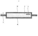
 本実施の形態1に係る真空断熱材は、無機繊維を含む芯材と、内面に第1熱溶着層を有する第1ラミネートフィルムと、内面に第2熱溶着層を有する第2ラミネートフィルムと、を備え、第1熱溶着層の密度が第2熱溶着層の密度よりも小さいことを特徴とする。
(Embodiment 1)
The vacuum heat insulating material according to the first embodiment includes a core material containing inorganic fibers, a first laminate film having a first heat-welded layer on the inner surface, a second laminate film having a second heat-welded layer on the inner surface, The density of the 1st heat welding layer is smaller than the density of the 2nd heat welding layer, It is characterized by the above-mentioned.
 これにより、対向するラミネートフィルム(外被材)の熱溶着層の密度を変えることによって、密度の小さい第1熱溶着層が夾雑物シール性とガラスに対する耐ピンホール性を真空断熱材に付与することが可能となる。また、相対的に密度の高い第2熱溶着層が真空断熱材へ侵入するガス又は水蒸気の量を低く抑えるといった作用を付与することが可能となる。 Thereby, by changing the density of the heat-welded layer of the opposing laminate film (covering material), the first heat-welded layer having a low density imparts a foreign matter sealing property and pinhole resistance to glass to the vacuum heat insulating material. It becomes possible. Moreover, it becomes possible to provide the effect | action that the 2nd heat welding layer with a comparatively high density suppresses the quantity of the gas or water vapor | steam which penetrate | invades into a vacuum heat insulating material low.
 また、本実施の形態1に係る真空断熱材の製造方法は、内面に第1熱溶着層を有する第1ラミネートフィルムと、内面に第1熱溶着層よりも密度の大きい第2熱溶着層を有する第2ラミネートフィルムと、を作製する(A)と、第1ラミネートフィルムの内面と第2ラミネートフィルムの内面とを互いに接触するように配置して積層体を作製する(B)と、積層体における周縁部の少なくとも一部を加熱圧縮して、第1熱溶着層と第2熱溶着層を熱溶着させる(C)と、を備える。 Moreover, the manufacturing method of the vacuum heat insulating material which concerns on this Embodiment 1 has the 1st laminated film which has a 1st heat welding layer in an inner surface, and the 2nd heat welding layer whose density is larger than a 1st heat welding layer in an inner surface. A second laminate film having (A), and arranging the inner surface of the first laminate film and the inner surface of the second laminate film in contact with each other to produce a laminate (B), (C) which heat-compresses at least one part of the peripheral part in and heat-welds a 1st heat welding layer and a 2nd heat welding layer.
 以下、本実施の形態1に係る真空断熱材の一例について、図1及び図2を参照しながら説明する。 Hereinafter, an example of the vacuum heat insulating material according to the first embodiment will be described with reference to FIGS. 1 and 2.
 [真空断熱材の構成]
 図1は、本実施の形態1に係る真空断熱材の概略構成を模式的に示す断面図である。図2は、図1に示す真空断熱材の封止部を拡大した断面図である。
[Configuration of vacuum insulation]
FIG. 1 is a cross-sectional view schematically showing a schematic configuration of the vacuum heat insulating material according to the first embodiment. FIG. 2 is an enlarged cross-sectional view of the sealing portion of the vacuum heat insulating material shown in FIG.
 図1に示すように、本実施の形態1に係る真空断熱材1は、矩形状に形成されていて、繊維を含む芯材2と、吸着剤3と、第1ラミネートフィルム4aと、第2ラミネートフィルム4bと、を備えている。芯材2及び吸着剤3は、第1ラミネートフィルム4a及び第2ラミネートフィルム4bで構成されている袋内に収納されていて、減圧密封されている。 As shown in FIG. 1, the vacuum heat insulating material 1 which concerns on this Embodiment 1 is formed in the rectangular shape, the core material 2 containing a fiber, the adsorbent 3, the 1st laminate film 4a, and the 2nd A laminate film 4b. The core material 2 and the adsorbent 3 are housed in a bag composed of the first laminate film 4a and the second laminate film 4b, and are sealed under reduced pressure.
 また、真空断熱材1は、第1ラミネートフィルム4a及び第2ラミネートフィルム4bの周縁部を熱溶着した封止部8を備えている。なお、封止部8において、後述する第1ラミネートフィルム4aの第1熱溶着層5aと第2ラミネートフィルム4bの第2熱溶着層5bが熱溶着して、1つの層になった部分を熱溶着層5という場合がある。 Moreover, the vacuum heat insulating material 1 is provided with the sealing part 8 which heat-welded the peripheral part of the 1st laminate film 4a and the 2nd laminate film 4b. In addition, in the sealing part 8, the 1st heat welding layer 5a of the 1st laminate film 4a mentioned later and the 2nd heat welding layer 5b of the 2nd laminate film 4b are heat-welded, and the part which became one layer is heat-processed. Sometimes referred to as a welded layer 5.
 芯材2は、真空断熱材1の骨材として微細空間を形成する役割を果たし、真空排気後の真空断熱材1の断熱部を形成するものである。本実施の形態1においては、芯材2として、ガラス繊維(例えば、グラスウール)が用いられている。 The core material 2 plays a role of forming a fine space as an aggregate of the vacuum heat insulating material 1 and forms a heat insulating portion of the vacuum heat insulating material 1 after evacuation. In the first embodiment, glass fiber (for example, glass wool) is used as the core material 2.
 なお、本実施の形態1においては、芯材2として、ガラス繊維を用いたが、これに限定されない、例えば、ロックウール、アルミナ繊維、及び金属繊維等の無機繊維、又はポリエチレンテレフタレート繊維等の公知の材料を用いてもよい。また、金属繊維を用いる場合は、金属の中でも比較的熱伝導性が低い金属からなる金属繊維を用いてもよい。 In the first embodiment, glass fiber is used as the core material 2, but is not limited thereto, for example, inorganic fibers such as rock wool, alumina fiber, metal fiber, or polyethylene terephthalate fiber. These materials may be used. Moreover, when using a metal fiber, you may use the metal fiber which consists of a metal with comparatively low heat conductivity among metals.
 繊維自体の弾性が高く、また繊維自体の熱伝導率が低く、かつ、工業的に安価なグラスウールを用いることが望ましい。さらに、繊維の繊維径は小さいほど真空断熱材の熱伝導率が低下する傾向にあるため、より小さい繊維径の繊維を用いることが望ましいが、汎用的でないため繊維のコストアップが予想される。したがって、真空断熱材用の繊維として一般的に使用されている比較的安価な平均繊維径が3μm~6μm程度の集合体からなるグラスウールがより望ましい。 It is desirable to use glass wool having high elasticity of the fiber itself, low thermal conductivity of the fiber itself, and industrially inexpensive. Furthermore, since the thermal conductivity of the vacuum heat insulating material tends to decrease as the fiber diameter of the fiber decreases, it is desirable to use a fiber having a smaller fiber diameter, but the fiber cost is expected to increase because it is not versatile. Accordingly, glass wool made of an aggregate having a relatively low average fiber diameter of about 3 to 6 μm, which is generally used as a fiber for a vacuum heat insulating material, is more desirable.
 吸着剤3は、真空包装後に芯材2の微細空隙から真空断熱材1中へ放出された残留ガス成分、及び真空断熱材1内へ侵入する水分又は気体を吸着除去する役割を果たすものである。吸着剤3としては、水分を吸着除去する水分吸着剤と大気ガス等のガスを吸着する気体吸着剤が挙げられる。 The adsorbent 3 serves to adsorb and remove residual gas components released into the vacuum heat insulating material 1 from the fine gaps of the core material 2 after vacuum packaging and moisture or gas that enters the vacuum heat insulating material 1. . Examples of the adsorbent 3 include a moisture adsorbent that adsorbs and removes moisture and a gas adsorbent that adsorbs a gas such as atmospheric gas.
 水分吸着剤としては、例えば、酸化カルシウム、又は酸化マグネシウム等の化学吸着物質、或いは、瀬尾ライトのような物理吸着物質を用いることができる。また、気体吸着剤は、気体中に含まれる非凝縮性気体を吸着できる吸着材料と容器で構成されている。 As the moisture adsorbent, for example, a chemical adsorption material such as calcium oxide or magnesium oxide, or a physical adsorption material such as Seolite can be used. The gas adsorbent is composed of an adsorbing material and a container that can adsorb a non-condensable gas contained in the gas.
 吸着材料としては、ジルコニウム、バナジウム及びタングステンからなる合金、鉄、マンガン、イットリウム、ランタンと希土類元素の1種の元素を含む合金、Ba-Li合金、並びに、金属イオンとイオン交換したゼオライト等が挙げられる。これらの吸着材料は、空気中の概ね75%を有する窒素を常温状態で吸着できるため、吸着剤3として使用すると、真空断熱材1は、高い真空度を得ることができる。 Examples of the adsorbing material include zirconium, vanadium and tungsten alloys, iron, manganese, yttrium, alloys containing one element of lanthanum and rare earth elements, Ba-Li alloys, and zeolites ion-exchanged with metal ions. It is done. Since these adsorbing materials can adsorb approximately 75% of nitrogen in the air at room temperature, the vacuum heat insulating material 1 can obtain a high degree of vacuum when used as the adsorbent 3.
 容器の材料としては、アルミニウム、鉄、胴、ステンレス等の金属材料が挙げられ、特に、コスト及び取り扱いを考慮するとアルミニウムが望ましい。 As the material of the container, metal materials such as aluminum, iron, barrel, and stainless steel can be cited, and aluminum is particularly preferable in consideration of cost and handling.
 図2に示すように、第1ラミネートフィルム4aは、第1熱溶着層5a、ガスバリア層6a、及び表面保護層7aを有していて、内面側から外面側に向かって、この順で配置されている。同様に、第2ラミネートフィルム4bは、第2熱溶着層5b、ガスバリア層6b、及び表面保護層7bを有していて、内面側から外面側に向かって、この順で配置されている。なお、第1ラミネートフィルム4a及び第2ラミネートフィルム4bは、外部から真空断熱材1内部への大気ガス侵入を抑制する役割を果たし、真空断熱材1の真空度を維持する役割を果たすものである。 As shown in FIG. 2, the first laminate film 4a has a first heat-welded layer 5a, a gas barrier layer 6a, and a surface protective layer 7a, and is arranged in this order from the inner surface side to the outer surface side. ing. Similarly, the 2nd laminate film 4b has the 2nd heat welding layer 5b, the gas barrier layer 6b, and the surface protection layer 7b, and is arrange | positioned in this order toward the outer surface side from the inner surface side. In addition, the 1st laminate film 4a and the 2nd laminate film 4b play the role which suppresses the atmospheric gas penetration | invasion from the outside to the inside of the vacuum heat insulating material 1, and plays the role which maintains the vacuum degree of the vacuum heat insulating material 1. .
 第1熱溶着層5a及び第2熱溶着層5bは、第1ラミネートフィルム4a及び第2ラミネートフィルム4bを互いに溶着し、真空断熱材1内部の真空を保持する役割を果たすものである。また、第1熱溶着層5a及び第2熱溶着層5bは、芯材2又は吸着剤3による真空断熱材1内部からの突刺し等からガスバリア層6a、6bを保護する役割を果たすものである。 The first heat-welded layer 5a and the second heat-welded layer 5b serve to weld the first laminate film 4a and the second laminate film 4b to each other and maintain the vacuum inside the vacuum heat insulating material 1. Moreover, the 1st heat welding layer 5a and the 2nd heat welding layer 5b play the role which protects gas barrier layer 6a, 6b from the puncture from the vacuum heat insulating material 1 inside with the core material 2 or the adsorption agent 3, etc. .
 第1熱溶着層5a及び第2熱溶着層5bは、熱可塑性樹脂からなる熱溶着フィルムで構成されていて、第1熱溶着層5aは、第2熱溶着層5bよりも密度が小さくなるように構成されている。 The 1st heat welding layer 5a and the 2nd heat welding layer 5b are comprised by the heat welding film which consists of a thermoplastic resin, and the 1st heat welding layer 5a is such that a density becomes smaller than the 2nd heat welding layer 5b. It is configured.
 なお、熱溶着フィルムの材質としては、特に限定されないが、低密度ポリエチレンフィルム、直鎖低密度ポリエチレンフィルム、中密度ポリエチレンフィルム、高密度ポリエチレンフィルム、ポリプロピレンフィルム、又はポリアクリロニトリルフィルム等の熱可塑性樹脂、或いはそれらの混合体が使用できる。その中でも、安価であり、かつ、ラミネート加工しやすいポリエチレンを選定するのが望ましい。第1熱溶着層5a及び第2熱溶着層5bは、同一の材質で構成されていてもよく、異なる材質で構成されていてもよい。 The material of the heat welding film is not particularly limited, but a thermoplastic resin such as a low density polyethylene film, a linear low density polyethylene film, a medium density polyethylene film, a high density polyethylene film, a polypropylene film, or a polyacrylonitrile film, Alternatively, a mixture thereof can be used. Among them, it is desirable to select polyethylene that is inexpensive and easy to laminate. The 1st heat welding layer 5a and the 2nd heat welding layer 5b may be comprised with the same material, and may be comprised with a different material.
 第1熱溶着層5aは、熱溶着強度及び柔軟性を増加させ、夾雑物シール性及び耐ピンホール性を向上させる観点から、密度が0.910~0.925g/cmであってもよい。また、第2熱溶着層5bは、真空断熱材1内へ透過するガス又は水蒸気の量を減少させる観点から、密度が0.935~0.950g/cmであってもよい。 The first heat-welded layer 5a may have a density of 0.910 to 0.925 g / cm 3 from the viewpoint of increasing the heat-welding strength and flexibility, and improving the contaminant sealing property and the pinhole resistance. . Further, the second heat-welded layer 5b may have a density of 0.935 to 0.950 g / cm 3 from the viewpoint of reducing the amount of gas or water vapor that permeates into the vacuum heat insulating material 1.
 ガスバリア層6a及びガスバリア層6bは、高いバリア性を有する1種類もしくは2種以上のフィルムから構成される層であり、第1ラミネートフィルム4a及び第2ラミネートフィルム4bに優れたガスバリア性を付与するものである。 The gas barrier layer 6a and the gas barrier layer 6b are layers composed of one kind or two or more kinds of films having high barrier properties, and impart excellent gas barrier properties to the first laminate film 4a and the second laminate film 4b. It is.
 ガスバリア層6a及びガスバリア層6bとしては、アルミニウム箔又は銅箔等の金属箔、ポリエチレンテレフタレートフィルム又はエチレン-ビニルアルコール共重合体へアルミニウム又は銅等の金属原子もしくはアルミナ又はシリカ等の金属酸化物を蒸着したフィルム、金属原子又は金属酸化物を蒸着した面にコーティング処理を施したフィルム等が使用できる。なお、本実施の形態1においては、ガスバリア層6a及びガスバリア層6bは、金属箔で構成されている。 As the gas barrier layer 6a and the gas barrier layer 6b, a metal foil such as an aluminum foil or a copper foil, a polyethylene terephthalate film or an ethylene-vinyl alcohol copolymer is deposited with a metal atom such as aluminum or copper or a metal oxide such as alumina or silica. A film having a coating treatment applied to a surface on which a metal atom or a metal oxide is deposited can be used. In the first embodiment, the gas barrier layer 6a and the gas barrier layer 6b are made of metal foil.
 表面保護層7a及び表面保護層7bは、それぞれ、外力から第1ラミネートフィルム4a及び第2ラミネートフィルム4b、特に、ガスバリア層6a、6bの傷つき又は破れを防ぐ役割を果たすものである。 The surface protective layer 7a and the surface protective layer 7b serve to prevent the first laminate film 4a and the second laminate film 4b, in particular, the gas barrier layers 6a and 6b from being damaged or torn from external force.
 表面保護層7a及び表面保護層7bとしては、ナイロンフィルム、ポリエチレンテレフタレートフィルム、ポリプロピレンフィルム等の公知の材料が使用でき、1種類のフィルムを重ねて使用してもよく、2種類以上のフィルムを重ねて使用してもよい。なお、本実施の形態1においては、表面保護層7aは、2枚のフィルム70a、71aを重ねて使用している。同様に、表面保護層7bは、2枚のフィルム70b、71bを重ねて使用している。 As the surface protective layer 7a and the surface protective layer 7b, known materials such as a nylon film, a polyethylene terephthalate film, and a polypropylene film can be used, and one type of film may be used in an overlapping manner, or two or more types of films may be stacked. May be used. In the first embodiment, the surface protective layer 7a uses two films 70a and 71a in an overlapping manner. Similarly, the surface protective layer 7b uses two films 70b and 71b in an overlapping manner.
 [真空断熱材の製造方法]
 次に、本実施の形態1に係る真空断熱材1の製造方法の一例について説明する。
[Method of manufacturing vacuum insulation]
Next, an example of the manufacturing method of the vacuum heat insulating material 1 which concerns on this Embodiment 1 is demonstrated.
 まず、矩形状の第1ラミネートフィルム4aと矩形状の第2ラミネートフィルム4bを作製し、第1ラミネートフィルム4aの第1熱溶着層5aと第2ラミネートフィルム4bの第2熱溶着層5bが互いに対向するように配置して、積層体を作製する。 First, a rectangular first laminate film 4a and a rectangular second laminate film 4b are prepared, and the first heat-welded layer 5a of the first laminate film 4a and the second heat-welded layer 5b of the second laminate film 4b are mutually connected. Arrange them so as to oppose each other to produce a laminate.
 次に、第1ラミネートフィルム4a及び第2ラミネートフィルム4bの周縁部の3辺を加熱しながら押圧して、第1熱溶着層5aと第2熱溶着層5bを熱溶着させて、袋状のラミネートフィルムを作製する。 Next, the three sides of the peripheral portions of the first laminate film 4a and the second laminate film 4b are pressed while being heated, so that the first heat-welded layer 5a and the second heat-welded layer 5b are heat-welded to form a bag-like shape. A laminate film is produced.
 ついで、袋状のラミネートフィルムの開口部から芯材2及び吸着剤3を挿入し、真空包装機を用いて、袋状のラミネートフィルム内部を真空引きしながら、開口部に位置する第1熱溶着層5aと第2熱溶着層5bを熱溶着して、真空断熱材1が得られる。 Next, the core material 2 and the adsorbent 3 are inserted from the opening of the bag-like laminate film, and the first heat welding located at the opening is evacuated while vacuuming the inside of the bag-like laminate film using a vacuum packaging machine. The vacuum heat insulating material 1 is obtained by thermally welding the layer 5a and the second heat welding layer 5b.
 [真空断熱材の評価試験]
 次に、本実施の形態1に係る真空断熱材1について、熱溶着層の密度を変えたときの効果について確認した評価試験の結果を以下に示す。
[Vacuum insulation evaluation test]
Next, about the vacuum heat insulating material 1 which concerns on this Embodiment 1, the result of the evaluation test confirmed about the effect when changing the density of a heat welding layer is shown below.
 なお、評価の優劣は真空断熱材用の熱溶着層として一般的に利用されている直鎖低密度ポリエチレンフィルム(密度0.923g/cm)を用いた比較例1の結果を基準とし、ピンホールの発生度合いが、比較例1と比較して20%以内の増加に収まり、かつ、60℃の恒温槽に1ヶ月放置した後の熱伝導率が、比較例1よりも小さければ優位性があると判断した。 The superiority or inferiority of the evaluation is based on the result of Comparative Example 1 using a linear low density polyethylene film (density 0.923 g / cm 3 ) that is generally used as a heat-welded layer for a vacuum heat insulating material. If the degree of occurrence of holes is within 20% of the increase in comparison with Comparative Example 1 and the thermal conductivity after being left in a constant temperature bath at 60 ° C. for one month is smaller than that of Comparative Example 1, it is superior. Judged that there was.
 (実施例1)
 厚さ15μmのナイロンフィルム70aと厚さ25μmのナイロンフィルム71aを表面保護層7aとし、厚さ6μmのアルミ箔をガスバリア層6aとし、厚さ50μmの直鎖低密度ポリエチレンフィルム(密度0.923g/cm)を第1熱溶着層5aとして、それぞれの層をウレタン接着剤で接着し、第1ラミネートフィルム4aを作製した。
(Example 1)
A nylon film 70a having a thickness of 15 μm and a nylon film 71a having a thickness of 25 μm are used as a surface protective layer 7a, an aluminum foil having a thickness of 6 μm is used as a gas barrier layer 6a, and a linear low density polyethylene film having a thickness of 50 μm (density 0.923 g / cm 3 ) were used as the first heat-welded layer 5a, and the respective layers were bonded with a urethane adhesive to produce a first laminate film 4a.
 また、厚さ15μmのナイロンフィルム70bと厚さ25μmのナイロンフィルム71bを表面保護層7bとし、厚さ6μmのアルミ箔をガスバリア層6bとし、厚さ50μmの直鎖低密度ポリエチレンフィルム(密度0.935g/cm)を第2熱溶着層5bとして、それぞれの層をウレタン接着剤で接着し、第2ラミネートフィルム4bを作製した。 Further, a nylon film 70b having a thickness of 15 μm and a nylon film 71b having a thickness of 25 μm are used as the surface protective layer 7b, an aluminum foil having a thickness of 6 μm is used as the gas barrier layer 6b, and a linear low-density polyethylene film having a thickness of 50 μm (density 0. 935 g / cm 3 ) was used as the second heat-welded layer 5b, and each layer was adhered with a urethane adhesive to produce a second laminate film 4b.
 そして、このようにして作製した第1ラミネートフィルム4a及び第2ラミネートフィルム4bを第1熱溶着層5a及び第2熱溶着層5bが互いに対向するように配置して、熱溶着し、熱溶着強度を測定したところ、幅15mmあたり82.4Nであった。 Then, the first laminated film 4a and the second laminated film 4b thus produced are arranged so that the first heat-welded layer 5a and the second heat-welded layer 5b face each other, heat-welded, and heat-welded strength. Was 82.4 N per 15 mm width.
 また、上記のように作製した第1ラミネートフィルム4a及び第2ラミネートフィルム4bからなる袋内にガラスのショット(ガラスが繊維化されなかった塊)を50mg封入し、真空パックした後に、ピンホール探知機(ピンホール探知機TRC-220A(サンコウ電子製)、以下の実施例及び比較例においても、同じ機器を使用)を使用して、ピンホールの個数をカウントしたところ、1mあたり2.1個であり、比較例1と同等の耐ピンホール性であることが判明した。 In addition, 50 mg of glass shot (a lump in which glass is not fiberized) is sealed in a bag made of the first laminate film 4a and the second laminate film 4b produced as described above, and after vacuum packing, pinhole detection is performed. machine (pinhole detector TRC-220A (manufactured by Sanko electronic), also in the following examples and comparative examples, using the same device) by using, as a result of counting the number of pinholes, 1 m 2 per 2.1 It was proved to have pinhole resistance equivalent to that of Comparative Example 1.
 さらに、上記のように作製した第1ラミネートフィルム4a及び第2ラミネートフィルム4bをそれぞれ、幅300mm、長さ400mmとなるよう切り出し、短辺が開口部となるよう互いに熱溶着し袋を製作した。なお、袋を製作する過程では、長辺部分の一箇所に平均繊維径が4μmのガラス繊維を数本、第1熱溶着層5a及び第2熱溶着層5bとともに熱溶着した。 Furthermore, the first laminate film 4a and the second laminate film 4b produced as described above were cut out so as to have a width of 300 mm and a length of 400 mm, respectively, and heat-welded to each other so that the short side was an opening, thereby producing a bag. In the process of manufacturing the bag, several glass fibers having an average fiber diameter of 4 μm were heat-welded together with the first heat-welding layer 5a and the second heat-welding layer 5b at one place on the long side portion.
 そして、この袋内にガラス繊維からなる幅250mm、長さ320mmの芯材2を吸着剤3とともに挿入し、開口部を減圧空間で熱溶着し、真空断熱材1を10枚作製した。この真空断熱材1の熱伝導率を熱伝導率計(熱伝導率測定装置HC-074 300(英弘精機製)、以下の実施例及び比較例においても、同じ機器を使用)で計測したところ、平均値は0.0020W/mKであった。また、この真空断熱材1を60℃の恒温槽に1ヶ月間放置した後に、熱伝導率を再度測定したところ、平均値は0.0039W/mKであった。 Then, a core material 2 made of glass fibers having a width of 250 mm and a length of 320 mm was inserted into the bag together with the adsorbent 3, and the openings were thermally welded in a reduced pressure space, thereby preparing 10 vacuum heat insulating materials 1. When the thermal conductivity of the vacuum heat insulating material 1 was measured with a thermal conductivity meter (thermal conductivity measuring device HC-074 300 (manufactured by Eihiro Seiki), the same equipment was used in the following examples and comparative examples) The average value was 0.0020 W / mK. Moreover, after leaving this vacuum heat insulating material 1 in a 60 degreeC thermostat for one month, when the heat conductivity was measured again, the average value was 0.0039 W / mK.
 (実施例2)
 厚さ15μmのナイロンフィルム70aと厚さ25μmのナイロンフィルム71aを表面保護層7aとし、厚さ6μmのアルミ箔をガスバリア層6aとし、厚さ50μmの直鎖低密度ポリエチレンフィルム(密度0.923g/cm)を第1熱溶着層5aとして、それぞれの層をウレタン接着剤で接着し、第1ラミネートフィルム4aを作製した。
(Example 2)
A nylon film 70a having a thickness of 15 μm and a nylon film 71a having a thickness of 25 μm are used as a surface protective layer 7a, an aluminum foil having a thickness of 6 μm is used as a gas barrier layer 6a, and a linear low density polyethylene film having a thickness of 50 μm (density 0.923 g / cm 3 ) were used as the first heat-welded layer 5a, and the respective layers were bonded with a urethane adhesive to produce a first laminate film 4a.
 また、厚さ15μmのナイロンフィルム70bと厚さ25μmのナイロンフィルム71bを表面保護層7bとし、厚さ6μmのアルミ箔をガスバリア層6bとし、厚さ50μmの中密度ポリエチレンフィルム(密度0.945g/cm)を第2熱溶着層5bとして、それぞれの層をウレタン接着剤で接着し、第2ラミネートフィルム4bを作製した。 Further, a 15 μm thick nylon film 70 b and a 25 μm thick nylon film 71 b are used as a surface protective layer 7 b, a 6 μm thick aluminum foil is used as a gas barrier layer 6 b, and a 50 μm thick medium density polyethylene film (density 0.945 g / cm 3 ) were used as the second heat-welded layer 5b, and the respective layers were bonded with a urethane adhesive to produce a second laminated film 4b.
 そして、このようにして作製した第1ラミネートフィルム4a及び第2ラミネートフィルム4bを第1熱溶着層5a及び第2熱溶着層5bが互いに対向するように配置して、熱溶着し、熱溶着強度を測定したところ、幅15mmあたり62.4Nであった。熱溶着層に中密度ポリエチレンのみを適用した比較例3と熱溶着強度を比較すると、熱溶着強度が48.6%増加した。これは、ポリエチレンの分子構造による現象である。 Then, the first laminated film 4a and the second laminated film 4b thus produced are arranged so that the first heat-welded layer 5a and the second heat-welded layer 5b face each other, heat-welded, and heat-welded strength. Was 62.4N per 15mm width. When the thermal welding strength was compared with Comparative Example 3 in which only the medium density polyethylene was applied to the thermal welding layer, the thermal welding strength increased by 48.6%. This is a phenomenon due to the molecular structure of polyethylene.
 ポリエチレンは主鎖となるエチレン鎖から分岐した側鎖が存在する。密度の低いポリエチレンは密度の高いポリエチレンに比べて側鎖が多いため、密度の低いポリエチレンと密度の高いポリエチレンを熱溶着すると、密度の低いポリエチレンの側鎖が密度の高いポリエチレンの主鎖と結合しやすくなるため、熱溶着強度が増加したものであると考えられる。 Polyethylene has side chains branched from the main ethylene chain. Low-density polyethylene has more side chains than high-density polyethylene, so when low-density polyethylene and high-density polyethylene are heat-welded, the low-density polyethylene side chains bind to the high-density polyethylene main chain. Since it becomes easy, it is considered that the thermal welding strength is increased.
 また、上記のように作製した第1ラミネートフィルム4a及び第2ラミネートフィルム4bからなる袋内にガラスのショットを50mg封入し、真空パックした後に、ピンホール探知機でピンホールの個数をカウントしたところ、1mあたり2.2個であり、比較例1に比べて4.7%の増加に留まった。 Also, 50 mg of glass shot was sealed in a bag made of the first laminate film 4a and the second laminate film 4b produced as described above, and after vacuum packing, the number of pinholes was counted with a pinhole detector. The number was 2.2 per 1 m 2 , which was an increase of 4.7% compared to Comparative Example 1.
 さらに、上記のように作製した第1ラミネートフィルム4a及び第2ラミネートフィルム4bをそれぞれ、幅300mm、長さ400mmとなるよう切り出し、短辺が開口部となるよう互いに熱溶着し袋を製作した。なお、袋を製作する過程では、長辺部分の一箇所に平均繊維径が4μmのガラス繊維を数本、第1熱溶着層5a及び第2熱溶着層5bとともに熱溶着した。 Furthermore, the first laminate film 4a and the second laminate film 4b produced as described above were cut out so as to have a width of 300 mm and a length of 400 mm, respectively, and heat-welded to each other so that the short side was an opening, thereby producing a bag. In the process of manufacturing the bag, several glass fibers having an average fiber diameter of 4 μm were heat-welded together with the first heat-welding layer 5a and the second heat-welding layer 5b at one place on the long side portion.
 そして、この袋内にガラス繊維からなる幅250mm、長さ320mmの芯材2を吸着剤3とともに挿入し、開口部を減圧空間で熱溶着し、真空断熱材1を10枚作製した。この真空断熱材1の熱伝導率を熱伝導率計で計測したところ、平均値は0.0022W/mKであった。 Then, a core material 2 made of glass fibers having a width of 250 mm and a length of 320 mm was inserted into the bag together with the adsorbent 3, and the openings were thermally welded in a reduced pressure space, thereby preparing 10 vacuum heat insulating materials 1. When the thermal conductivity of the vacuum heat insulating material 1 was measured with a thermal conductivity meter, the average value was 0.0022 W / mK.
 また、この真空断熱材1を60℃の恒温槽に1ヶ月間放置した後に、熱伝導率を再度測定したところ、平均値は0.0035W/mKであり、比較例1の結果よりも耐熱試験後の劣化が小さくなることを確認した。 Moreover, when this heat-insulating material 1 was left in a thermostat at 60 ° C. for one month and then the thermal conductivity was measured again, the average value was 0.0035 W / mK, which is a heat resistance test than the result of Comparative Example 1. It was confirmed that the later deterioration was reduced.
 (実施例3)
 厚さ15μmのナイロンフィルム70aと厚さ25μmのナイロンフィルム71aを表面保護層7aとし、厚さ6μmのアルミ箔をガスバリア層6aとし、厚さ50μmの直鎖低密度ポリエチレンフィルム(密度0.923g/cm)を第1熱溶着層5aとして、それぞれの層をウレタン接着剤で接着し、第1ラミネートフィルム4aを作製した。
(Example 3)
A nylon film 70a having a thickness of 15 μm and a nylon film 71a having a thickness of 25 μm are used as a surface protective layer 7a, an aluminum foil having a thickness of 6 μm is used as a gas barrier layer 6a, and a linear low density polyethylene film having a thickness of 50 μm (density 0.923 g / cm 3 ) were used as the first heat-welded layer 5a, and the respective layers were bonded with a urethane adhesive to produce a first laminate film 4a.
 また、厚さ15μmのナイロンフィルム70bと厚さ25μmのナイロンフィルム71bを表面保護層7bとし、厚さ6μmのアルミ箔をガスバリア層6bとし、厚さ50μmの高密度ポリエチレンフィルム(密度0.950g/cm)を第2熱溶着層5bとして、それぞれの層をウレタン接着剤で接着し、第2ラミネートフィルム4bを作製した。 A nylon film 70b having a thickness of 15 μm and a nylon film 71b having a thickness of 25 μm are used as the surface protective layer 7b, an aluminum foil having a thickness of 6 μm is used as the gas barrier layer 6b, and a high-density polyethylene film having a thickness of 50 μm (density 0.950 g / cm 3 ) were used as the second heat-welded layer 5b, and the respective layers were bonded with a urethane adhesive to produce a second laminated film 4b.
 そして、このようにして作製した第1ラミネートフィルム4a及び第2ラミネートフィルム4bを第1熱溶着層5a及び第2熱溶着層5bが互いに対向するように配置して、熱溶着し、熱溶着強度を測定したところ、幅15mmあたり57.8Nであった。熱溶着層に高密度ポリエチレンのみを適用した比較例3と熱溶着強度を比較すると、熱溶着強度が68.5%増加した。これは実施例2と同様に、ポリエチレンの分子構造による現象である。 Then, the first laminated film 4a and the second laminated film 4b thus produced are arranged so that the first heat-welded layer 5a and the second heat-welded layer 5b face each other, heat-welded, and heat-welded strength. Was 57.8 N per 15 mm width. When the thermal welding strength was compared with Comparative Example 3 in which only high-density polyethylene was applied to the thermal welding layer, the thermal welding strength increased by 68.5%. This is a phenomenon due to the molecular structure of polyethylene, as in Example 2.
 ポリエチレンは主鎖となるエチレン鎖から分岐した側鎖が存在する。密度の低いポリエチレンは密度の高いポリエチレンに比べて側鎖が多く、密度の低いポリエチレンと密度の高いポリエチレンを熱溶着すると、密度の低いポリエチレンの側鎖が密度の高いポリエチレンの主鎖と結合しやすくなるため、熱溶着強度が増加したものであると考えられる。 Polyethylene has side chains branched from the main ethylene chain. Low-density polyethylene has more side chains than high-density polyethylene, and when low-density polyethylene and high-density polyethylene are heat-welded, the low-density polyethylene side chains easily bond to the high-density polyethylene main chain. Therefore, it is considered that the thermal welding strength is increased.
 また、上記のように作製した第1ラミネートフィルム4a及び第2ラミネートフィルム4bからなる袋内にガラスのショットを50mg封入し、真空パックした後に、ピンホール探知機でピンホールの個数をカウントしたところ、1mあたり2.4個であり、14,3%の増加に留まった。 Also, 50 mg of glass shot was sealed in a bag made of the first laminate film 4a and the second laminate film 4b produced as described above, and after vacuum packing, the number of pinholes was counted with a pinhole detector. The number was 2.4 per 1 m 2 , which was an increase of 14.3%.
 さらに、上記のように作製した第1ラミネートフィルム4a及び第2ラミネートフィルム4bをそれぞれ、幅300mm、長さ400mmとなるよう切り出し、短辺が開口部となるよう互いに熱溶着し袋を製作した。なお、袋を製作する過程では、長辺部分の一箇所に平均繊維径が4μmのガラス繊維を数本熱溶着層とともに熱溶着した。 Furthermore, the first laminate film 4a and the second laminate film 4b produced as described above were cut out so as to have a width of 300 mm and a length of 400 mm, respectively, and heat-welded to each other so that the short side was an opening, thereby producing a bag. In the process of manufacturing the bag, several glass fibers having an average fiber diameter of 4 μm were heat-welded together with several heat-welding layers at one place on the long side portion.
 そして、この袋内にガラス繊維からなる幅250mm、長さ320mmの芯材2を吸着剤3とともに挿入し、開口部を減圧空間で熱溶着し、真空断熱材1を10枚作製した。この真空断熱材1の熱伝導率を熱伝導率計で計測したところ、平均値は0.0023W/mKであった。 Then, a core material 2 made of glass fibers having a width of 250 mm and a length of 320 mm was inserted into the bag together with the adsorbent 3, and the openings were thermally welded in a reduced pressure space, thereby preparing 10 vacuum heat insulating materials 1. When the heat conductivity of this vacuum heat insulating material 1 was measured with the heat conductivity meter, the average value was 0.0023 W / mK.
 また、この真空断熱材1を60℃の恒温槽に1ヶ月間放置した後に、熱伝導率を再度測定したところ、平均値は0.0033W/mKであり、比較例1の結果よりも耐熱試験後の劣化が小さくなることを確認した。 Moreover, after leaving this vacuum heat insulating material 1 to stand in a 60 degreeC thermostat for one month, when the heat conductivity was measured again, an average value is 0.0033 W / mK and is a heat resistance test rather than the result of the comparative example 1. It was confirmed that the later deterioration was reduced.
 (比較例1)
 厚さ15μmのナイロンフィルム70aと厚さ25μmのナイロンフィルム71aを表面保護層7aとし、厚さ6μmのアルミ箔をガスバリア層6aとし、厚さ50μmの直鎖低密度ポリエチレンフィルム(密度0.923g/cm)を第1熱溶着層5aとして、それぞれの層をウレタン接着剤で接着し、第1ラミネートフィルム4aを作製した。
(Comparative Example 1)
A nylon film 70a having a thickness of 15 μm and a nylon film 71a having a thickness of 25 μm are used as a surface protective layer 7a, an aluminum foil having a thickness of 6 μm is used as a gas barrier layer 6a, and a linear low density polyethylene film having a thickness of 50 μm (density 0.923 g / cm 3 ) were used as the first heat-welded layer 5a, and the respective layers were bonded with a urethane adhesive to produce a first laminate film 4a.
 また、第2ラミネートフィルム4bは第1ラミネートフィルム4aと同一のものを用いた。そして、このようにして作製した第1ラミネートフィルム4a及び第2ラミネートフィルム4bを第1熱溶着層5a及び第2熱溶着層5bが互いに対向するように配置して、熱溶着し、熱溶着強度を測定したところ、幅15mmあたり84.5Nであった。 The second laminate film 4b was the same as the first laminate film 4a. Then, the first laminated film 4a and the second laminated film 4b thus produced are arranged so that the first heat-welded layer 5a and the second heat-welded layer 5b face each other, heat-welded, and heat-welded strength. Was measured to be 84.5 N per 15 mm width.
 また、上記のように作製した第1ラミネートフィルム4a及び第2ラミネートフィルム4bからなる袋内にガラスのショットを50mg封入し、真空パックした後にピンホール探知機でピンホールの個数をカウントしたところ、1mあたり2.1個であった。 Moreover, when 50 mg of glass shot was enclosed in a bag made of the first laminate film 4a and the second laminate film 4b produced as described above, and after vacuum packing, the number of pinholes was counted with a pinhole detector, The number was 2.1 per 1 m 2 .
 さらに、上記のように作製した第1ラミネートフィルム4a及び第2ラミネートフィルム4bをそれぞれ、幅300mm、長さ400mmとなるよう切り出し、短辺が開口部となるよう互いに熱溶着し袋を製作した。なお、袋を製作する過程では、長辺部分の一箇所に平均繊維径が4μmのガラス繊維を数本熱溶着層とともに熱溶着した。 Furthermore, the first laminate film 4a and the second laminate film 4b produced as described above were cut out so as to have a width of 300 mm and a length of 400 mm, respectively, and heat-welded to each other so that the short side was an opening, thereby producing a bag. In the process of manufacturing the bag, several glass fibers having an average fiber diameter of 4 μm were heat-welded together with several heat-welding layers at one place on the long side portion.
 そして、この袋内にガラス繊維からなる幅250mm、長さ320mmの芯材2を吸着剤3とともに挿入し、開口部を減圧空間で熱溶着し、真空断熱材1を10枚作製した。この真空断熱材1の熱伝導率を熱伝導率計で計測したところ、平均値は0.0021W/mKであった。 Then, a core material 2 made of glass fibers having a width of 250 mm and a length of 320 mm was inserted into the bag together with the adsorbent 3, and the openings were thermally welded in a reduced pressure space, thereby preparing 10 vacuum heat insulating materials 1. When the thermal conductivity of the vacuum heat insulating material 1 was measured with a thermal conductivity meter, the average value was 0.0021 W / mK.
 また、この真空断熱材を60℃の恒温槽に1ヶ月間放置した後に、熱伝導率を再度測定したところ、平均値は0.0042W/mKであった。 Further, when this vacuum heat insulating material was left in a constant temperature bath at 60 ° C. for one month and then the thermal conductivity was measured again, the average value was 0.0042 W / mK.
 (比較例2)
 厚さ15μmのナイロンフィルム70aと厚さ25μmのナイロンフィルム71aを表面保護層7aとし、厚さ6μmのアルミ箔をガスバリア層6aとし、厚さ50μmの直鎖低密度ポリエチレンフィルム(密度0.935g/cm)を第1熱溶着層5aとして、それぞれの層をウレタン接着剤で接着し、第1ラミネートフィルム4aを作製した。
(Comparative Example 2)
A nylon film 70a having a thickness of 15 μm and a nylon film 71a having a thickness of 25 μm are used as the surface protective layer 7a, an aluminum foil having a thickness of 6 μm is used as the gas barrier layer 6a, and a linear low-density polyethylene film having a thickness of 50 μm (density 0.935 g / cm 3 ) were used as the first heat-welded layer 5a, and the respective layers were bonded with a urethane adhesive to produce a first laminate film 4a.
 また、第2ラミネートフィルム4bは第1ラミネートフィルム4aと同一のものを用いた。そして、このようにして作製した第1ラミネートフィルム4a及び第2ラミネートフィルム4bを第1熱溶着層5a及び第2熱溶着層5bが互いに対向するように配置して、熱溶着し、熱溶着強度を測定したところ、幅15mmあたり73.9Nであった。 The second laminate film 4b was the same as the first laminate film 4a. Then, the first laminated film 4a and the second laminated film 4b thus produced are arranged so that the first heat-welded layer 5a and the second heat-welded layer 5b face each other, heat-welded, and heat-welded strength. Was measured to be 73.9 N per 15 mm width.
 また、上記のように作製した第1ラミネートフィルム4a及び第2ラミネートフィルム4bからなる袋内にガラスのショットを50mg封入し、真空パックした後に、ピンホール探知機でピンホールの個数をカウントしたところ、1mあたり3.2個であり、52.4%と大幅に増加した。 Also, 50 mg of glass shot was sealed in a bag made of the first laminate film 4a and the second laminate film 4b produced as described above, and after vacuum packing, the number of pinholes was counted with a pinhole detector. It was 3.2 per 1 m 2 , which was a significant increase of 52.4%.
 さらに、上記のように作製した第1ラミネートフィルム4a及び第2ラミネートフィルム4bをそれぞれ、幅300mm、長さ400mmとなるよう切り出し、短辺が開口部となるよう互いに熱溶着し袋を製作した。なお、袋を製作する過程では、長辺部分の一箇所に平均繊維径が4μmのガラス繊維を数本熱溶着層とともに熱溶着した。 Furthermore, the first laminate film 4a and the second laminate film 4b produced as described above were cut out so as to have a width of 300 mm and a length of 400 mm, respectively, and heat-welded to each other so that the short side was an opening, thereby producing a bag. In the process of manufacturing the bag, several glass fibers having an average fiber diameter of 4 μm were heat-welded together with several heat-welding layers at one place on the long side portion.
 そして、この袋内にガラス繊維からなる幅250mm、長さ320mmの芯材2を吸着剤3とともに挿入し、開口部を減圧空間で熱溶着し、真空断熱材1を10枚作製した。この真空断熱材1の熱伝導率を熱伝導率計で計測したところ、平均値は0.0018W/mKであった。 Then, a core material 2 made of glass fibers having a width of 250 mm and a length of 320 mm was inserted into the bag together with the adsorbent 3, and the openings were thermally welded in a reduced pressure space, thereby preparing 10 vacuum heat insulating materials 1. When the thermal conductivity of the vacuum heat insulating material 1 was measured with a thermal conductivity meter, the average value was 0.0018 W / mK.
 また、この真空断熱材1を60℃の恒温槽に1ヶ月間放置した後に、熱伝導率を再度測定したところ、平均値は0.0037W/mKであり、比較例1の結果よりも耐熱試験後の劣化が大きくなることを確認した。 Moreover, when this vacuum heat insulating material 1 was left to stand in a 60 degreeC thermostat for one month, when the heat conductivity was measured again, an average value is 0.0037 W / mK and is a heat test rather than the result of the comparative example 1. It was confirmed that the later deterioration became large.
 (比較例3)
 厚さ15μmのナイロンフィルム70aと厚さ25μmのナイロンフィルム71aを表面保護層7aとし、厚さ6μmのアルミ箔をガスバリア層6aとし、厚さ50μmの中密度ポリエチレンフィルム(密度0.945g/cm)を第1熱溶着層5aとして、それぞれの層をウレタン接着剤で接着し、第1ラミネートフィルム4aを作製した。
(Comparative Example 3)
A nylon film 70a having a thickness of 15 μm and a nylon film 71a having a thickness of 25 μm are used as the surface protective layer 7a, an aluminum foil having a thickness of 6 μm is used as the gas barrier layer 6a, and a medium density polyethylene film (density 0.945 g / cm 3) having a thickness of 50 μm. ) As the first heat-welded layer 5a, and the respective layers were adhered with a urethane adhesive to produce a first laminate film 4a.
 また、第2ラミネートフィルム4bは第1ラミネートフィルム4aと同一のものを用いた。そして、このようにして作製した第1ラミネートフィルム4a及び第2ラミネートフィルム4bを第1熱溶着層5a及び第2熱溶着層5bが互いに対向するように配置して、熱溶着し、熱溶着強度を測定したところ、幅15mmあたり42.0Nであった。 The second laminate film 4b was the same as the first laminate film 4a. Then, the first laminated film 4a and the second laminated film 4b thus produced are arranged so that the first heat-welded layer 5a and the second heat-welded layer 5b face each other, heat-welded, and heat-welded strength. Was measured to be 42.0 N per 15 mm width.
 また、上記のように作製した第1ラミネートフィルム4a及び第2ラミネートフィルム4bからなる袋内にガラスのショットを50mg封入し、真空パックした後に、ピンホール探知機でピンホールの個数をカウントしたところ、1mあたり4.9個であり、133.3%と大幅に増加した。 Also, 50 mg of glass shot was sealed in a bag made of the first laminate film 4a and the second laminate film 4b produced as described above, and after vacuum packing, the number of pinholes was counted with a pinhole detector. It was 4.9 per 1 m 2 , which was a great increase to 133.3%.
 さらに、上記のように作製した第1ラミネートフィルム4a及び第2ラミネートフィルム4bをそれぞれ、幅300mm、長さ400mmとなるよう切り出し、短辺が開口部となるよう互いに熱溶着し袋を製作した。なお、袋を製作する過程では、長辺部分の一箇所に平均繊維径が4μmのガラス繊維を数本熱溶着層とともに熱溶着した。 Furthermore, the first laminate film 4a and the second laminate film 4b produced as described above were cut out so as to have a width of 300 mm and a length of 400 mm, respectively, and heat-welded to each other so that the short side was an opening, thereby producing a bag. In the process of manufacturing the bag, several glass fibers having an average fiber diameter of 4 μm were heat-welded together with several heat-welding layers at one place on the long side portion.
 そして、この袋内にガラス繊維からなる幅250mm、長さ320mmの芯材2を吸着剤3とともに挿入し、開口部を減圧空間で熱溶着し、真空断熱材1を10枚作製した。この真空断熱材1の熱伝導率を熱伝導率計で計測したところ、平均値は0.0024W/mKであったが、夾雑物シール性が悪かったため、ガラス繊維とともに熱溶着した箇所から空気が流入し、真空を維持することができなかった真空断熱材1を1枚発見した。 Then, a core material 2 made of glass fibers having a width of 250 mm and a length of 320 mm was inserted into the bag together with the adsorbent 3, and the openings were thermally welded in a reduced pressure space, thereby preparing 10 vacuum heat insulating materials 1. When the thermal conductivity of the vacuum heat insulating material 1 was measured with a thermal conductivity meter, the average value was 0.0024 W / mK. However, since the sealing property of foreign substances was poor, air was introduced from the location where the glass fiber was thermally welded. One vacuum heat insulating material 1 was found that flowed in and could not maintain the vacuum.
 また、この真空断熱材1の熱伝導率を熱伝導率計で計測したところ、0.0322W/mKであったため、長期に亘って真空断熱材1の断熱効果を維持できないと判断し、60℃の恒温槽に1ヶ月間放置する耐熱試験を中止した。 Further, when the thermal conductivity of the vacuum heat insulating material 1 was measured with a thermal conductivity meter, it was 0.0322 W / mK, so it was determined that the heat insulating effect of the vacuum heat insulating material 1 could not be maintained over a long period of time. The heat resistance test that was left in a thermostatic bath for 1 month was stopped.
 (比較例4)
 厚さ15μmのナイロンフィルム70aと厚さ25μmのナイロンフィルム71aを表面保護層7aとし、厚さ6μmのアルミ箔をガスバリア層6aとし、厚さ50μmの高密度ポリエチレンフィルム(密度0.950g/cm)を第1熱溶着層5aとして、それぞれの層をウレタン接着剤で接着し、第1ラミネートフィルム4aを作製した。
(Comparative Example 4)
A nylon film 70a having a thickness of 15 μm and a nylon film 71a having a thickness of 25 μm are used as the surface protective layer 7a, an aluminum foil having a thickness of 6 μm is used as the gas barrier layer 6a, and a high-density polyethylene film having a thickness of 50 μm (density 0.950 g / cm 3 ) As the first heat-welded layer 5a, and the respective layers were adhered with a urethane adhesive to produce a first laminate film 4a.
 また、第2ラミネートフィルム4bは第1ラミネートフィルム4aと同一のものを用いた。そして、このようにして作製した第1ラミネートフィルム4a及び第2ラミネートフィルム4bを第1熱溶着層5a及び第2熱溶着層5bが互いに対向するように配置して、熱溶着し、熱溶着強度を測定したところ、幅15mmあたり34.3Nであった。 The second laminate film 4b was the same as the first laminate film 4a. Then, the first laminated film 4a and the second laminated film 4b thus produced are arranged so that the first heat-welded layer 5a and the second heat-welded layer 5b face each other, heat-welded, and heat-welded strength. Was 34.3 N per 15 mm width.
 また、上記のように作製した第1ラミネートフィルム4a及び第2ラミネートフィルム4bからなる袋内にガラスのショットを50mg封入し、真空パックした後に、ピンホール探知機でピンホールの個数をカウントしたところ、1mあたり6.4個であり、204.8%と大幅に増加した。 Also, 50 mg of glass shot was sealed in a bag made of the first laminate film 4a and the second laminate film 4b produced as described above, and after vacuum packing, the number of pinholes was counted with a pinhole detector. It was 6.4 per 1 m 2 , which was a great increase of 204.8%.
 さらに、上記のように作製した第1ラミネートフィルム4a及び第2ラミネートフィルム4bをそれぞれ、幅300mm、長さ400mmとなるよう切り出し、短辺が開口部となるよう互いに熱溶着し袋を製作した。なお、袋を製作する過程では、長辺部分の一箇所に平均繊維径が4μmのガラス繊維を数本熱溶着層とともに熱溶着した。 Furthermore, the first laminate film 4a and the second laminate film 4b produced as described above were cut out so as to have a width of 300 mm and a length of 400 mm, respectively, and heat-welded to each other so that the short side was an opening, thereby producing a bag. In the process of manufacturing the bag, several glass fibers having an average fiber diameter of 4 μm were heat-welded together with several heat-welding layers at one place on the long side portion.
 そして、この袋内にガラス繊維からなる幅250mm、長さ320mmの芯材2を吸着剤3とともに挿入し、開口部を減圧空間で熱溶着し、真空断熱材1を10枚作製した。この真空断熱材1の熱伝導率を熱伝導率計で計測したところ、平均値は0.0022W/mKであったが、夾雑物シール性が悪かったため、ガラス繊維とともに熱溶着した箇所から空気が流入し、真空を維持することができなかった真空断熱材1を1枚発見した。 Then, a core material 2 made of glass fibers having a width of 250 mm and a length of 320 mm was inserted into the bag together with the adsorbent 3, and the openings were thermally welded in a reduced pressure space, thereby preparing 10 vacuum heat insulating materials 1. When the thermal conductivity of the vacuum heat insulating material 1 was measured with a thermal conductivity meter, the average value was 0.0022 W / mK. However, since the sealing property of foreign substances was poor, air was introduced from the location where the glass fiber was thermally welded. One vacuum heat insulating material 1 was found that flowed in and could not maintain the vacuum.
 また、この真空断熱材1の熱伝導率を熱伝導率計で計測したところ、0.0328W/mKであったため、長期に亘って真空断熱材1の断熱効果を維持できないと判断し、60℃の恒温槽に1ヶ月間放置する耐熱試験を中止した。 Further, when the thermal conductivity of the vacuum heat insulating material 1 was measured with a thermal conductivity meter, it was 0.0328 W / mK, so it was determined that the heat insulating effect of the vacuum heat insulating material 1 could not be maintained over a long period of time, and 60 ° C. The heat resistance test that was left in a thermostatic bath for 1 month was stopped.
 以上のように構成された実施例1~3及び比較例1~4の真空断熱材1について、熱溶着層の密度を変えたときの効果について確認した結果を図3に示す。 FIG. 3 shows the results of confirming the effect of changing the density of the heat-welded layer in the vacuum heat insulating materials 1 of Examples 1 to 3 and Comparative Examples 1 to 4 configured as described above.
 図3は、熱溶着層の密度を変えたときの真空断熱材の効果について確認した結果を示すものである。 FIG. 3 shows the result of confirming the effect of the vacuum heat insulating material when the density of the heat-welded layer is changed.
 図3に示すように、第1熱溶着層5aの密度を第2熱溶着層5bの密度よりも小さくすることによって、夾雑物シール性の改善とガスバリア性の改善を両立することが可能であることが確認できた。なお、実施例1~3において、第1熱溶着層5aを直鎖低密度ポリエチレンとしたが、低密度ポリエチレンを用いても同様の効果が得られる。 As shown in FIG. 3, by making the density of the first heat-welded layer 5a smaller than the density of the second heat-welded layer 5b, it is possible to improve both the contaminant sealing property and the gas barrier property. I was able to confirm. In Examples 1 to 3, the first heat-welded layer 5a is a linear low-density polyethylene, but the same effect can be obtained by using low-density polyethylene.
 (実施の形態2)
 本実施の形態2に係る真空断熱材は、実施の形態1に係る真空断熱材において、第1ラミネートフィルムは金属箔を有し、第2ラミネートフィルムは蒸着膜を有している。なお、本実施の形態2に係る真空断熱材は、上記特徴以外は、実施の形態1に係る真空断熱材と同様に構成してもよい。
(Embodiment 2)
The vacuum heat insulating material according to Embodiment 2 is the vacuum heat insulating material according to Embodiment 1, in which the first laminate film has a metal foil and the second laminate film has a vapor deposition film. In addition, you may comprise the vacuum heat insulating material which concerns on this Embodiment 2 similarly to the vacuum heat insulating material which concerns on Embodiment 1 except the said characteristic.
 金属箔を備えたラミネートフィルムと比較して、蒸着膜を備えたラミネートフィルムは異物に対する耐ピンホール性が優れている。このため、蒸着膜を備えたラミネートフィルム側に相対的に密度の高い第2熱溶着層を適用しても、耐ピンホール性の低下を最小限に抑えることが可能となる。また、ラミネートフィルムの積層方向に侵入するガス又は水蒸気を金属箔で防止することにより、真空断熱材の断熱効果を長期に亘って高く保つことが可能となる。 Compared with a laminate film provided with a metal foil, a laminate film provided with a vapor deposition film has excellent pinhole resistance against foreign matters. For this reason, even if the second heat-welded layer having a relatively high density is applied to the laminate film side provided with the vapor deposition film, it is possible to minimize the decrease in pinhole resistance. Moreover, it becomes possible to keep the heat insulation effect of a vacuum heat insulating material high over a long period of time by preventing the gas or water vapor which penetrate | invades in the lamination direction of a laminate film with metal foil.
 以下、本実施の形態2に係る真空断熱材の一例について、図4及び図5を参照しながら説明する。 Hereinafter, an example of the vacuum heat insulating material according to the second embodiment will be described with reference to FIGS. 4 and 5.
 [真空断熱材の構成]
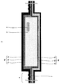
 図4は、本実施の形態2に係る真空断熱材の概略構成を模式的に示す断面図である。図5は、図4に示す真空断熱材の封止部を拡大した断面図である。
[Configuration of vacuum insulation]
FIG. 4 is a cross-sectional view schematically showing a schematic configuration of the vacuum heat insulating material according to the second embodiment. FIG. 5 is an enlarged cross-sectional view of the sealing portion of the vacuum heat insulating material shown in FIG.
 図4及び図5に示すように、本実施の形態2に係る真空断熱材1は、実施の形態1に係る真空断熱材1と基本的構成は同じであるが、第2ラミネートフィルム4bのガスバリア層6bの構成が異なる。 As shown in FIGS. 4 and 5, the vacuum heat insulating material 1 according to the second embodiment has the same basic configuration as the vacuum heat insulating material 1 according to the first embodiment, but the gas barrier of the second laminate film 4b. The configuration of the layer 6b is different.
 具体的には、ガスバリア層6bは、基材80bに金属原子を蒸着させた蒸着膜90bと、基材81bに金属原子を蒸着させた蒸着膜91bと、を有している。そして、本実施の形態2においては、蒸着膜90bと蒸着膜91bとが互いに接触するように配置されている。 Specifically, the gas barrier layer 6b includes a vapor deposition film 90b in which metal atoms are vapor-deposited on the base material 80b, and a vapor deposition film 91b in which metal atoms are vapor-deposited on the base material 81b. And in this Embodiment 2, the vapor deposition film 90b and the vapor deposition film 91b are arrange | positioned so that it may mutually contact.
 基材80b及び基材81bとしては、例えば、ポリエチレンテレフタレートフィルム又はエチレン-ビニルアルコール共重合体が挙げられる。 Examples of the base material 80b and the base material 81b include a polyethylene terephthalate film or an ethylene-vinyl alcohol copolymer.
 なお、本実施の形態2においては、蒸着膜90bと蒸着膜91bとが互いに接触するように配置する形態を採用したが、これに限定されず、基材80bと基材81bとが互いに接触するように配置する形態を採用してもよい。 In the second embodiment, a configuration is adopted in which the vapor deposition film 90b and the vapor deposition film 91b are arranged so as to be in contact with each other. However, the present invention is not limited to this, and the base material 80b and the base material 81b are in contact with each other. A form of arranging in this way may be adopted.
 [真空断熱材の評価試験]
 次に、本実施の形態2に係る真空断熱材1について、熱溶着層の密度を変えたときの効果について確認した評価試験の結果を以下に示す。
[Vacuum insulation evaluation test]
Next, about the vacuum heat insulating material 1 which concerns on this Embodiment 2, the result of the evaluation test confirmed about the effect when changing the density of a heat welding layer is shown below.
 なお、評価の優劣は真空断熱材用の熱溶着層として一般的に利用されている直鎖低密度ポリエチレンフィルム(密度0.923g/cm)を金属箔と複層した比較例1の結果を基準とし、ピンホールの発生度合いが、比較例1と比較して、20%以内の増加に収まれば優位性があると判断した。 In addition, the superiority or inferiority of the evaluation is the result of Comparative Example 1 in which a linear low density polyethylene film (density 0.923 g / cm 3 ) generally used as a heat welding layer for a vacuum heat insulating material is laminated with a metal foil. As a reference, it was judged that there was an advantage if the degree of occurrence of pinholes was within 20% increase compared to Comparative Example 1.
 また、ガスバリア性については、真空断熱材用の熱溶着層として一般的に利用されている直鎖低密度ポリエチレンフィルム(密度0.923g/cm)を蒸着膜と複層した比較例5の結果を基準とし、60℃の恒温槽に1ヶ月放置した後の熱伝導率が比較例5よりも小さければ優位性があると判断した。 Moreover, about gas barrier property, the result of the comparative example 5 which laminated | stacked the linear low density polyethylene film (density 0.923g / cm < 3 >) generally used as a heat welding layer for vacuum heat insulating materials with a vapor deposition film. Was determined to be superior if the thermal conductivity after being left in a constant temperature bath at 60 ° C. for one month was smaller than that of Comparative Example 5.
 (実施例4)
 厚さ15μmのナイロンフィルム70aと厚さ25μmのナイロンフィルム71aを表面保護層7aとし、厚さ6μmのアルミ箔をガスバリア層6aとし、厚さ50μmの直鎖低密度ポリエチレンフィルム(密度0.923g/cm)を第1熱溶着層5aとして、それぞれの層をウレタン接着剤で接着し、第1ラミネートフィルム4aを作製した。
Example 4
A nylon film 70a having a thickness of 15 μm and a nylon film 71a having a thickness of 25 μm are used as a surface protective layer 7a, an aluminum foil having a thickness of 6 μm is used as a gas barrier layer 6a, and a linear low density polyethylene film having a thickness of 50 μm (density 0.923 g / cm 3 ) were used as the first heat-welded layer 5a, and the respective layers were bonded with a urethane adhesive to produce a first laminate film 4a.
 また、厚さ25μmのナイロンフィルムを表面保護層7bとし、厚さ12μmのポリエチレンテレフタレートフィルム(基材80b)上にアルミ蒸着膜(蒸着膜90b)を施したフィルムと、厚さ12μmのエチレン-ビニルアルコール共重合体フィルム(基材81b)上にアルミ蒸着膜(蒸着膜91b)を施したフィルムをアルミ蒸着膜が向かい合うよう複層したものをガスバリア層6bとし、厚さ50μmの直鎖低密度ポリエチレンフィルム(密度0.935g/cm)を第2熱溶着層5bとして、それぞれの層をウレタン接着剤で接着し、第2ラミネートフィルム4bを作製した。 In addition, a 25 μm thick nylon film is used as the surface protective layer 7b, a 12 μm thick polyethylene terephthalate film (base material 80b) with an aluminum deposited film (deposited film 90b), and a 12 μm thick ethylene-vinyl film. A film obtained by applying an aluminum vapor deposition film (deposition film 91b) on an alcohol copolymer film (base material 81b) so that the aluminum vapor deposition film faces each other is used as a gas barrier layer 6b, and a linear low density polyethylene having a thickness of 50 μm. A film (density 0.935 g / cm 3 ) was used as the second heat-welded layer 5b, and each layer was adhered with a urethane adhesive to produce a second laminated film 4b.
 そして、このようにして作製した第1ラミネートフィルム4a及び第2ラミネートフィルム4bを第1熱溶着層5a及び第2熱溶着層5bが互いに対向するように配置して、熱溶着し、熱溶着強度を測定したところ、幅15mmあたり86.1Nであった。 Then, the first laminated film 4a and the second laminated film 4b thus produced are arranged so that the first heat-welded layer 5a and the second heat-welded layer 5b face each other, heat-welded, and heat-welded strength. Was 86.1 N per 15 mm width.
 また、上記のように作製した第1ラミネートフィルム4a及び第2ラミネートフィルム4bからなる袋内にガラスのショットを50mg封入し、真空パックした後に、ピンホール探知機でピンホールの個数をカウントしたところ、1mあたり1.7個であり、比較例1よりも優れた耐ピンホール性であることが判明した。 Also, 50 mg of glass shot was sealed in a bag made of the first laminate film 4a and the second laminate film 4b produced as described above, and after vacuum packing, the number of pinholes was counted with a pinhole detector. It was 1.7 per 1 m 2 , and it was found that the pinhole resistance was superior to that of Comparative Example 1.
 これは、ガスバリア層6bの蒸着膜90bと蒸着膜91bのラミネート強度が小さいため、蒸着膜90bと蒸着膜91bが剥離しやすいので、ショットがラミネートフィルムに突き刺さる際の衝撃を蒸着膜90bと蒸着膜91bが剥離することで、緩和したものと考えられる。 This is because the vapor deposition film 90b and the vapor deposition film 91b of the gas barrier layer 6b have a low laminate strength, so the vapor deposition film 90b and the vapor deposition film 91b are easy to peel off. It is considered that 91b peeled off.
 さらに、上記のように作製した第1ラミネートフィルム4a及び第2ラミネートフィルム4bをそれぞれ、幅300mm、長さ400mmとなるよう切り出し、短辺が開口部となるよう互いに熱溶着し袋を製作した。なお、袋を製作する過程では、長辺部分の一箇所に平均繊維径が4μmのガラス繊維を数本熱溶着層とともに熱溶着した。 Furthermore, the first laminate film 4a and the second laminate film 4b produced as described above were cut out so as to have a width of 300 mm and a length of 400 mm, respectively, and heat-welded to each other so that the short side was an opening, thereby producing a bag. In the process of manufacturing the bag, several glass fibers having an average fiber diameter of 4 μm were heat-welded together with several heat-welding layers at one place on the long side portion.
 そして、この袋内にガラス繊維からなる幅250mm、長さ320mmの芯材2を吸着剤3とともに挿入し、開口部を減圧空間で熱溶着し、真空断熱材1を10枚作製した。この真空断熱材1の熱伝導率を熱伝導率計で計測したところ、平均値は0.0022W/mKであった。 Then, a core material 2 made of glass fibers having a width of 250 mm and a length of 320 mm was inserted into the bag together with the adsorbent 3, and the openings were thermally welded in a reduced pressure space, thereby preparing 10 vacuum heat insulating materials 1. When the thermal conductivity of the vacuum heat insulating material 1 was measured with a thermal conductivity meter, the average value was 0.0022 W / mK.
 また、この真空断熱材1を60℃の恒温槽に1ヶ月間放置した後に、熱伝導率を再度測定したところ、平均値は0.0044W/mKであった。 Further, after this vacuum heat insulating material 1 was left in a constant temperature bath at 60 ° C. for one month and then the thermal conductivity was measured again, the average value was 0.0044 W / mK.
 (実施例5)
 厚さ15μmのナイロンフィルム70aと厚さ25μmのナイロンフィルム71aを表面保護層7aとし、厚さ6μmのアルミ箔をガスバリア層6aとし、厚さ50μmの直鎖低密度ポリエチレンフィルム(密度0.923g/cm)を第1熱溶着層5aとして、それぞれの層をウレタン接着剤で接着し、第1ラミネートフィルム4aを作製した。
(Example 5)
A nylon film 70a having a thickness of 15 μm and a nylon film 71a having a thickness of 25 μm are used as a surface protective layer 7a, an aluminum foil having a thickness of 6 μm is used as a gas barrier layer 6a, and a linear low density polyethylene film having a thickness of 50 μm (density 0.923 g / cm 3 ) were used as the first heat-welded layer 5a, and the respective layers were bonded with a urethane adhesive to produce a first laminate film 4a.
 また、厚さ25μmのナイロンフィルムを表面保護層7bとし、厚さ12μmのポリエチレンテレフタレートフィルム(基材80b)上にアルミ蒸着膜(蒸着膜90b)を施したフィルムと、厚さ12μmのエチレン-ビニルアルコール共重合体フィルム(基材81b)上にアルミ蒸着膜(蒸着膜91b)を施したフィルムをアルミ蒸着膜が向かい合うよう複層したものをガスバリア層6bとし、厚さ50μmの中密度ポリエチレンフィルム(密度0.945g/cm)を第2熱溶着層5bとして、それぞれの層をウレタン接着剤で接着し、第2ラミネートフィルム4bを作製した。 In addition, a 25 μm thick nylon film is used as the surface protective layer 7b, a 12 μm thick polyethylene terephthalate film (base material 80b) with an aluminum deposited film (deposited film 90b), and a 12 μm thick ethylene-vinyl film. A film in which an aluminum vapor deposition film (deposition film 91b) is formed on an alcohol copolymer film (base material 81b) is formed as a gas barrier layer 6b so that the aluminum vapor deposition film faces each other, and a 50 μm thick medium density polyethylene film ( A density of 0.945 g / cm 3 ) was used as the second heat-welded layer 5b, and each layer was adhered with a urethane adhesive to produce a second laminate film 4b.
 そして、このようにして作製した第1ラミネートフィルム4a及び第2ラミネートフィルム4bを第1熱溶着層5a及び第2熱溶着層5bが互いに対向するように配置して、熱溶着し、熱溶着強度を測定したところ、幅15mmあたり63.3Nであった。 Then, the first laminated film 4a and the second laminated film 4b thus produced are arranged so that the first heat-welded layer 5a and the second heat-welded layer 5b face each other, heat-welded, and heat-welded strength. Was 63.3N per 15 mm width.
 また、上記のように作製した第1ラミネートフィルム4a及び第2ラミネートフィルム4bからなる袋内にガラスのショットを50mg封入し、真空パックした後に、ピンホール探知機でピンホールの個数をカウントしたところ、1mあたり1.9個であり、比較例1よりも優れた耐ピンホール性であることが判明した。 Also, 50 mg of glass shot was sealed in a bag made of the first laminate film 4a and the second laminate film 4b produced as described above, and after vacuum packing, the number of pinholes was counted with a pinhole detector. It was 1.9 per 1 m 2 , and it was found that the pinhole resistance was superior to that of Comparative Example 1.
 これは、ガスバリア層6bの蒸着膜90bと蒸着膜91bのラミネート強度が小さいため、蒸着膜90bと蒸着膜91bが剥離しやすいので、ショットがラミネートフィルムに突き刺さる際の衝撃を蒸着膜90bと蒸着膜91bが剥離することで、緩和したものと考えられる。 This is because the vapor deposition film 90b and the vapor deposition film 91b of the gas barrier layer 6b have a low laminate strength, so the vapor deposition film 90b and the vapor deposition film 91b are easy to peel off. It is considered that 91b peeled off.
 さらに、上記のように作製した第1ラミネートフィルム4a及び第2ラミネートフィルム4bをそれぞれ、幅300mm、長さ400mmとなるよう切り出し、短辺が開口部となるよう互いに熱溶着し袋を製作した。なお、袋を製作する過程では、長辺部分の一箇所に平均繊維径が4μmのガラス繊維を数本熱溶着層とともに熱溶着した。 Furthermore, the first laminate film 4a and the second laminate film 4b produced as described above were cut out so as to have a width of 300 mm and a length of 400 mm, respectively, and heat-welded to each other so that the short side was an opening, thereby producing a bag. In the process of manufacturing the bag, several glass fibers having an average fiber diameter of 4 μm were heat-welded together with several heat-welding layers at one place on the long side portion.
 そして、この袋内にガラス繊維からなる幅250mm、長さ320mmの芯材2を吸着剤3とともに挿入し、開口部を減圧空間で熱溶着し、真空断熱材1を10枚作製した。この真空断熱材1の熱伝導率を熱伝導率計で計測したところ、平均値は0.0023W/mKであった。 Then, a core material 2 made of glass fibers having a width of 250 mm and a length of 320 mm was inserted into the bag together with the adsorbent 3, and the openings were thermally welded in a reduced pressure space, thereby preparing 10 vacuum heat insulating materials 1. When the heat conductivity of this vacuum heat insulating material 1 was measured with the heat conductivity meter, the average value was 0.0023 W / mK.
 また、この真空断熱材1を60℃の恒温槽に1ヶ月間放置した後に、熱伝導率を再度測定したところ、平均値は0.0041W/mKであった。 Further, after this vacuum heat insulating material 1 was left in a constant temperature bath at 60 ° C. for one month and then the thermal conductivity was measured again, the average value was 0.0041 W / mK.
 (実施例6)
 厚さ15μmのナイロンフィルム70aと厚さ25μmのナイロンフィルム71aを表面保護層7aとし、厚さ6μmのアルミ箔をガスバリア層6aとし、厚さ50μmの直鎖低密度ポリエチレンフィルム(密度0.923g/cm)を第1熱溶着層5aとして、それぞれの層をウレタン接着剤で接着し、第1ラミネートフィルム4aを作製した。
(Example 6)
A nylon film 70a having a thickness of 15 μm and a nylon film 71a having a thickness of 25 μm are used as a surface protective layer 7a, an aluminum foil having a thickness of 6 μm is used as a gas barrier layer 6a, and a linear low density polyethylene film having a thickness of 50 μm (density 0.923 g / cm 3 ) were used as the first heat-welded layer 5a, and the respective layers were bonded with a urethane adhesive to produce a first laminate film 4a.
 また、厚さ25μmのナイロンフィルムを表面保護層7bとし、厚さ12μmのポリエチレンテレフタレートフィルム(基材80b)上にアルミ蒸着膜(蒸着膜90b)を施したフィルムと、厚さ12μmのエチレン-ビニルアルコール共重合体フィルム(基材81b)上にアルミ蒸着膜(蒸着膜91b)を施したフィルムをアルミ蒸着膜が向かい合うよう複層したものをガスバリア層6bとし、厚さ50μmの高密度ポリエチレンフィルム(密度0.950g/cm)を第2熱溶着層5bとして、それぞれの層をウレタン接着剤で接着し、第2ラミネートフィルム4bを作製した。 In addition, a 25 μm thick nylon film is used as the surface protective layer 7b, a 12 μm thick polyethylene terephthalate film (base material 80b) with an aluminum deposited film (deposited film 90b), and a 12 μm thick ethylene-vinyl film. A film in which an aluminum vapor deposition film (deposition film 91b) is applied on an alcohol copolymer film (base material 81b) is formed as a gas barrier layer 6b so that the aluminum vapor deposition film faces each other, and a 50 μm thick high-density polyethylene film ( A density of 0.950 g / cm 3 ) was used as the second heat-welded layer 5b, and each layer was adhered with a urethane adhesive to produce a second laminate film 4b.
 そして、このようにして作製した第1ラミネートフィルム4a及び第2ラミネートフィルム4bを第1熱溶着層5a及び第2熱溶着層5bが互いに対向するように配置して、熱溶着し、熱溶着強度を測定したところ、幅15mmあたり60.7Nであった。 Then, the first laminated film 4a and the second laminated film 4b thus produced are arranged so that the first heat-welded layer 5a and the second heat-welded layer 5b face each other, heat-welded, and heat-welded strength. Was 60.7 N per 15 mm width.
 また、上記のように作製した第1ラミネートフィルム4a及び第2ラミネートフィルム4bからなる袋内にガラスのショットを50mg封入し、真空パックした後に、ピンホール探知機でピンホールの個数をカウントしたところ、1mあたり2.0個であり、比較例1よりも優れた耐ピンホール性であることが判明した。 Also, 50 mg of glass shot was sealed in a bag made of the first laminate film 4a and the second laminate film 4b produced as described above, and after vacuum packing, the number of pinholes was counted with a pinhole detector. It was 2.0 per 1 m 2 , and it was found that the pinhole resistance was superior to that of Comparative Example 1.
 これは、ガスバリア層6bの蒸着膜90bと蒸着膜91bのラミネート強度が小さいため、蒸着膜90bと蒸着膜91bが剥離しやすいので、ショットがラミネートフィルムに突き刺さる際の衝撃を蒸着膜90bと蒸着膜91bが剥離することで、緩和したものと考えられる。 This is because the vapor deposition film 90b and the vapor deposition film 91b of the gas barrier layer 6b have a low laminate strength, so the vapor deposition film 90b and the vapor deposition film 91b are easy to peel off. It is considered that 91b peeled off.
 さらに、上記のように作製した第1ラミネートフィルム4a及び第2ラミネートフィルム4bをそれぞれ、幅300mm、長さ400mmとなるよう切り出し、短辺が開口部となるよう互いに熱溶着し袋を製作した。なお、袋を製作する過程では、長辺部分の一箇所に平均繊維径が4μmのガラス繊維を数本熱溶着層とともに熱溶着した。 Furthermore, the first laminate film 4a and the second laminate film 4b produced as described above were cut out so as to have a width of 300 mm and a length of 400 mm, respectively, and heat-welded to each other so that the short side was an opening, thereby producing a bag. In the process of manufacturing the bag, several glass fibers having an average fiber diameter of 4 μm were heat-welded together with several heat-welding layers at one place on the long side portion.
 そして、この袋内にガラス繊維からなる幅250mm、長さ320mmの芯材2を吸着剤3とともに挿入し、開口部を減圧空間で熱溶着し、真空断熱材1を10枚作製した。この真空断熱材1の熱伝導率を熱伝導率計で計測したところ、平均値は0.0019W/mKであった。 Then, a core material 2 made of glass fibers having a width of 250 mm and a length of 320 mm was inserted into the bag together with the adsorbent 3, and the openings were thermally welded in a reduced pressure space, thereby preparing 10 vacuum heat insulating materials 1. When the thermal conductivity of the vacuum heat insulating material 1 was measured with a thermal conductivity meter, the average value was 0.0019 W / mK.
 また、この真空断熱材1を60℃の恒温槽に1ヶ月間放置した後に、熱伝導率を再度測定したところ、平均値は0.0040W/mKであった。 Moreover, when this vacuum heat insulating material 1 was left in a constant temperature bath at 60 ° C. for one month and then the thermal conductivity was measured again, the average value was 0.0040 W / mK.
 (比較例5)
 厚さ15μmのナイロンフィルム70aと厚さ25μmのナイロンフィルム71aを表面保護層7aとし、厚さ6μmのアルミ箔をガスバリア層6aとし、厚さ50μmの直鎖低密度ポリエチレンフィルム(密度0.923g/cm)を第1熱溶着層5aとして、それぞれの層をウレタン接着剤で接着し、第1ラミネートフィルム4aを作製した。
(Comparative Example 5)
A nylon film 70a having a thickness of 15 μm and a nylon film 71a having a thickness of 25 μm are used as a surface protective layer 7a, an aluminum foil having a thickness of 6 μm is used as a gas barrier layer 6a, and a linear low density polyethylene film having a thickness of 50 μm (density 0.923 g / cm 3 ) were used as the first heat-welded layer 5a, and the respective layers were bonded with a urethane adhesive to produce a first laminate film 4a.
 また、厚さ25μmのナイロンフィルムを表面保護層7bとし、厚さ12μmのポリエチレンテレフタレートフィルム(基材80b)上にアルミ蒸着膜(蒸着膜90b)を施したフィルムと、厚さ12μmのエチレン-ビニルアルコール共重合体フィルム(基材81b)上にアルミ蒸着膜(蒸着膜91b)を施したフィルムをアルミ蒸着膜が向かい合うよう複層したものをガスバリア層6bとし、厚さ50μmの直鎖低密度ポリエチレンフィルム(密度0.923g/cm)を第2熱溶着層5bとして、それぞれの層をウレタン接着剤で接着し、第2ラミネートフィルム4bを作製した。 In addition, a 25 μm thick nylon film is used as the surface protective layer 7b, a 12 μm thick polyethylene terephthalate film (base material 80b) with an aluminum deposited film (deposited film 90b), and a 12 μm thick ethylene-vinyl film. A film obtained by applying an aluminum vapor deposition film (deposition film 91b) on an alcohol copolymer film (base material 81b) so that the aluminum vapor deposition film faces each other is used as a gas barrier layer 6b, and a linear low density polyethylene having a thickness of 50 μm. A film (density 0.923 g / cm 3 ) was used as the second heat-welded layer 5b, and each layer was adhered with a urethane adhesive to produce a second laminate film 4b.
 そして、このようにして作製した第1ラミネートフィルム4a及び第2ラミネートフィルム4bを第1熱溶着層5a及び第2熱溶着層5bが互いに対向するように配置して、熱溶着し、熱溶着強度を測定したところ、幅15mmあたり88.2Nであった。 Then, the first laminated film 4a and the second laminated film 4b thus produced are arranged so that the first heat-welded layer 5a and the second heat-welded layer 5b face each other, heat-welded, and heat-welded strength. Was 88.2 N per 15 mm width.
 また、上記のように作製した第1ラミネートフィルム4a及び第2ラミネートフィルム4bからなる袋内にガラスのショットを50mg封入し、真空パックした後に、ピンホール探知機でピンホールの個数をカウントしたところ、1mあたり1.5個であった。 Also, 50 mg of glass shot was sealed in a bag made of the first laminate film 4a and the second laminate film 4b produced as described above, and after vacuum packing, the number of pinholes was counted with a pinhole detector. The number was 1.5 per 1 m 2 .
 さらに、上記のように作製した第1ラミネートフィルム4a及び第2ラミネートフィルム4bをそれぞれ、幅300mm、長さ400mmとなるよう切り出し、短辺が開口部となるよう互いに熱溶着し袋を製作した。なお、袋を製作する過程では、長辺部分の一箇所に平均繊維径が4μmのガラス繊維を数本熱溶着層とともに熱溶着した。 Furthermore, the first laminate film 4a and the second laminate film 4b produced as described above were cut out so as to have a width of 300 mm and a length of 400 mm, respectively, and heat-welded to each other so that the short side was an opening, thereby producing a bag. In the process of manufacturing the bag, several glass fibers having an average fiber diameter of 4 μm were heat-welded together with several heat-welding layers at one place on the long side portion.
 そして、この袋内にガラス繊維からなる幅250mm、長さ320mmの芯材2を吸着剤3とともに挿入し、開口部を減圧空間で熱溶着し、真空断熱材を10枚作製した。この真空断熱材1の熱伝導率を熱伝導率計で計測したところ、平均値は0.0023W/mKであった。 Then, the core material 2 made of glass fiber having a width of 250 mm and a length of 320 mm was inserted into the bag together with the adsorbent 3, and the openings were thermally welded in a reduced pressure space to produce 10 vacuum heat insulating materials. When the heat conductivity of this vacuum heat insulating material 1 was measured with the heat conductivity meter, the average value was 0.0023 W / mK.
 また、この真空断熱材1を60℃の恒温槽に1ヶ月間放置した後に、熱伝導率を再度測定したところ、平均値は0.0048W/mKであった。 Further, when this vacuum heat insulating material 1 was left in a thermostat at 60 ° C. for one month and then the thermal conductivity was measured again, the average value was 0.0048 W / mK.
 (比較例6)
 厚さ15μmのナイロンフィルム70aと厚さ25μmのナイロンフィルム71aを表面保護層7aとし、厚さ6μmのアルミ箔をガスバリア層6aとし、厚さ50μmの直鎖低密度ポリエチレンフィルム(密度0.935g/cm)を第1熱溶着層5aとして、それぞれの層をウレタン接着剤で接着し、第1ラミネートフィルム4aを作製した。
(Comparative Example 6)
A nylon film 70a having a thickness of 15 μm and a nylon film 71a having a thickness of 25 μm are used as the surface protective layer 7a, an aluminum foil having a thickness of 6 μm is used as the gas barrier layer 6a, and a linear low-density polyethylene film having a thickness of 50 μm (density 0.935 g / cm 3 ) were used as the first heat-welded layer 5a, and the respective layers were bonded with a urethane adhesive to produce a first laminate film 4a.
 また、厚さ25μmのナイロンフィルムを表面保護層7bとし、厚さ12μmのポリエチレンテレフタレートフィルム(基材80b)上にアルミ蒸着膜(蒸着膜90b)を施したフィルムと、厚さ12μmのエチレン-ビニルアルコール共重合体フィルム(基材81b)上にアルミ蒸着膜(蒸着膜91b)を施したフィルムをアルミ蒸着膜が向かい合うよう複層したものをガスバリア層6bとし、厚さ50μmの直鎖低密度ポリエチレンフィルム(密度0.923g/cm)を第2熱溶着層5bとして、それぞれの層をウレタン接着剤で接着し、第2ラミネートフィルム4bを作製した。 In addition, a 25 μm thick nylon film is used as the surface protective layer 7b, a 12 μm thick polyethylene terephthalate film (base material 80b) with an aluminum deposited film (deposited film 90b), and a 12 μm thick ethylene-vinyl film. A film obtained by applying an aluminum vapor deposition film (deposition film 91b) on an alcohol copolymer film (base material 81b) so that the aluminum vapor deposition film faces each other is used as a gas barrier layer 6b, and a linear low density polyethylene having a thickness of 50 μm. A film (density 0.923 g / cm 3 ) was used as the second heat-welded layer 5b, and each layer was adhered with a urethane adhesive to produce a second laminate film 4b.
 そして、このようにして作製した第1ラミネートフィルム4a及び第2ラミネートフィルム4bを第1熱溶着層5a及び第2熱溶着層5bが互いに対向するように配置して、熱溶着し、熱溶着強度を測定したところ、幅15mmあたり85.6Nと実施例4とほぼ同等の強度であった。 Then, the first laminated film 4a and the second laminated film 4b thus produced are arranged so that the first heat-welded layer 5a and the second heat-welded layer 5b face each other, heat-welded, and heat-welded strength. As a result, 85.6 N per 15 mm width was almost the same as that of Example 4.
 しかし、上記のように作製した第1ラミネートフィルム4a及び第2ラミネートフィルム4bからなる袋内にガラスのショットを50mg封入し、真空パックした後に、ピンホール探知機でピンホールの個数をカウントしたところ、1mあたり2.3個となり、比較例1及び実施例4に比べて耐ピンホール性が劣ることが判明した。 However, when 50 mg of glass shot is sealed in a bag made of the first laminate film 4a and the second laminate film 4b produced as described above, vacuum packed, and then the number of pinholes is counted with a pinhole detector. It was 2.3 per 1 m 2 , and it was found that the pinhole resistance was inferior to that of Comparative Example 1 and Example 4.
 これは、相対的に密度の高い第1熱溶着層5aを金属箔とともにラミネートしたため、第1ラミネートフィルム4a側に大量のピンホールが発生したことが原因であると考えられる。 This is considered to be because a large number of pinholes were generated on the first laminate film 4a side because the relatively dense first heat-welded layer 5a was laminated together with the metal foil.
 さらに、上記のように作製した第1ラミネートフィルム4a及び第2ラミネートフィルム4bをそれぞれ、幅300mm、長さ400mmとなるよう切り出し、短辺が開口部となるよう互いに熱溶着し袋を製作した。なお、袋を製作する過程では、長辺部分の一箇所に平均繊維径が4μmのガラス繊維を数本熱溶着層とともに熱溶着した。 Furthermore, the first laminate film 4a and the second laminate film 4b produced as described above were cut out so as to have a width of 300 mm and a length of 400 mm, respectively, and heat-welded to each other so that the short side was an opening, thereby producing a bag. In the process of manufacturing the bag, several glass fibers having an average fiber diameter of 4 μm were heat-welded together with several heat-welding layers at one place on the long side portion.
 そして、この袋内にガラス繊維からなる幅250mm、長さ320mmの芯材2を吸着剤3とともに挿入し、開口部を減圧空間で熱溶着し、真空断熱材1を10枚作製した。この真空断熱材1の熱伝導率を熱伝導率計で計測したところ、平均値は0.0020W/mKであった。 Then, a core material 2 made of glass fibers having a width of 250 mm and a length of 320 mm was inserted into the bag together with the adsorbent 3, and the openings were thermally welded in a reduced pressure space, thereby preparing 10 vacuum heat insulating materials 1. When the thermal conductivity of the vacuum heat insulating material 1 was measured with a thermal conductivity meter, the average value was 0.0020 W / mK.
 また、この真空断熱材1を60℃の恒温槽に1ヶ月間放置した後に、熱伝導率を再度測定したところ、平均値は0.0043W/mKと実施例4と大きな差は見られなかった。 Moreover, after leaving this vacuum heat insulating material 1 in a 60 degreeC thermostat for one month, when the thermal conductivity was measured again, the average value was 0.0043 W / mK and the big difference with Example 4 was not seen. .
 (比較例7)
 厚さ15μmのナイロンフィルム70aと厚さ25μmのナイロンフィルム71aを表面保護層7aとし、厚さ6μmのアルミ箔をガスバリア層6aとし、厚さ50μmの中密度ポリエチレンフィルム(密度0.945g/cm)を第1熱溶着層5aとして、それぞれの層をウレタン接着剤で接着し、第1ラミネートフィルム4aを作製した。
(Comparative Example 7)
The nylon film 71a of nylon film 70a and the thickness 25μm of thickness 15μm and a surface protective layer 7a, an aluminum foil having a thickness of 6μm and the gas barrier layer 6a, density polyethylene film in a thickness of 50 [mu] m (density 0.945 g / cm 3 ) As the first heat-welded layer 5a, and the respective layers were adhered with a urethane adhesive to produce a first laminate film 4a.
 また、厚さ25μmのナイロンフィルムを表面保護層7bとし、厚さ12μmのポリエチレンテレフタレートフィルム(基材80b)上にアルミ蒸着膜(蒸着膜90b)を施したフィルムと、厚さ12μmのエチレン-ビニルアルコール共重合体フィルム(基材81b)上にアルミ蒸着膜(蒸着膜91b)を施したフィルムをアルミ蒸着膜が向かい合うよう複層したものをガスバリア層6bとし、厚さ50μmの直鎖低密度ポリエチレンフィルム(密度0.923g/cm)を第2熱溶着層5bとして、それぞれの層をウレタン接着剤で接着し、第2ラミネートフィルム4bを作製した。 In addition, a 25 μm thick nylon film is used as the surface protective layer 7b, a 12 μm thick polyethylene terephthalate film (base material 80b) with an aluminum deposited film (deposited film 90b), and a 12 μm thick ethylene-vinyl film. A film obtained by applying an aluminum vapor deposition film (deposition film 91b) on an alcohol copolymer film (base material 81b) so that the aluminum vapor deposition film faces each other is used as a gas barrier layer 6b, and a linear low density polyethylene having a thickness of 50 μm. A film (density 0.923 g / cm 3 ) was used as the second heat-welded layer 5b, and each layer was adhered with a urethane adhesive to produce a second laminate film 4b.
 そして、このようにして作製した第1ラミネートフィルム4a及び第2ラミネートフィルム4bを第1熱溶着層5a及び第2熱溶着層5bが互いに対向するように配置して、熱溶着し、熱溶着強度を測定したところ、幅15mmあたり60.5Nと実施例5とほぼ同等の強度であった。 Then, the first laminated film 4a and the second laminated film 4b thus produced are arranged so that the first heat-welded layer 5a and the second heat-welded layer 5b face each other, heat-welded, and heat-welded strength. As a result, it was 60.5 N per 15 mm width, which was almost the same strength as in Example 5.
 しかし、上記のように作製した第1ラミネートフィルム4a及び第2ラミネートフィルム4bからなる袋内にガラスのショットを50mg封入し、真空パックした後に、ピンホール探知機でピンホールの個数をカウントしたところ、1mあたり3.2個となり、比較例1及び実施例5に比べて、耐ピンホール性が劣ることが判明した。 However, when 50 mg of glass shot is sealed in a bag made of the first laminate film 4a and the second laminate film 4b produced as described above, vacuum packed, and then the number of pinholes is counted with a pinhole detector. It was 3.2 per 1 m 2 , and it was found that the pinhole resistance was inferior to that of Comparative Example 1 and Example 5.
 これは、相対的に密度の高い第1熱溶着層5aを金属箔とともにラミネートしたため、第1ラミネートフィルム4a側に大量のピンホールが発生したことが原因であると考えられる。 This is considered to be because a large number of pinholes were generated on the first laminate film 4a side because the relatively dense first heat-welded layer 5a was laminated together with the metal foil.
 さらに、上記のように作製した第1ラミネートフィルム4a及び第2ラミネートフィルム4bをそれぞれ、幅300mm、長さ400mmとなるよう切り出し、短辺が開口部となるよう互いに熱溶着し袋を製作した。なお、袋を製作する過程では、長辺部分の一箇所に平均繊維径が4μmのガラス繊維を数本熱溶着層とともに熱溶着した。 Furthermore, the first laminate film 4a and the second laminate film 4b produced as described above were cut out so as to have a width of 300 mm and a length of 400 mm, respectively, and heat-welded to each other so that the short side was an opening, thereby producing a bag. In the process of manufacturing the bag, several glass fibers having an average fiber diameter of 4 μm were heat-welded together with several heat-welding layers at one place on the long side portion.
 そして、この袋内にガラス繊維からなる幅250mm、長さ320mmの芯材2を吸着剤3とともに挿入し、開口部を減圧空間で熱溶着し、真空断熱材1を10枚作製した。この真空断熱材1の熱伝導率を熱伝導率計で計測したところ、平均値は0.0022W/mKであったが、夾雑物シール性が悪かったため、ガラス繊維とともに熱溶着した箇所から空気が流入し、真空を維持することができなかった真空断熱材1を1枚発見した。 Then, a core material 2 made of glass fibers having a width of 250 mm and a length of 320 mm was inserted into the bag together with the adsorbent 3, and the openings were thermally welded in a reduced pressure space, thereby preparing 10 vacuum heat insulating materials 1. When the thermal conductivity of the vacuum heat insulating material 1 was measured with a thermal conductivity meter, the average value was 0.0022 W / mK. However, since the sealing property of foreign substances was poor, air was introduced from the location where the glass fiber was thermally welded. One vacuum heat insulating material 1 was found that flowed in and could not maintain the vacuum.
 また、この真空断熱材1の熱伝導率を熱伝導率計で計測したところ、0.0336W/mKであったため、長期に亘って真空断熱材1の断熱効果を維持できないと判断し、60℃の恒温槽に1ヶ月間放置する耐熱試験を中止した。 Further, when the thermal conductivity of the vacuum heat insulating material 1 was measured with a heat conductivity meter, it was 0.0336 W / mK, so it was determined that the heat insulating effect of the vacuum heat insulating material 1 could not be maintained over a long period of time, and 60 ° C. The heat resistance test that was left in a thermostatic bath for 1 month was stopped.
 (比較例8)
 厚さ15μmのナイロンフィルム70aと厚さ25μmのナイロンフィルム71aを表面保護層7aとし、厚さ6μmのアルミ箔をガスバリア層6aとし、厚さ50μmの高密度ポリエチレンフィルム(密度0.950g/cm)を第1熱溶着層5aとして、それぞれの層をウレタン接着剤で接着し、第1ラミネートフィルム4aを作製した。
(Comparative Example 8)
A nylon film 70a having a thickness of 15 μm and a nylon film 71a having a thickness of 25 μm are used as the surface protective layer 7a, an aluminum foil having a thickness of 6 μm is used as the gas barrier layer 6a, and a high-density polyethylene film having a thickness of 50 μm (density 0.950 g / cm 3 ) As the first heat-welded layer 5a, and the respective layers were adhered with a urethane adhesive to produce a first laminate film 4a.
 また、厚さ25μmのナイロンフィルムを表面保護層7bとし、厚さ12μmのポリエチレンテレフタレートフィルム(基材80b)上にアルミ蒸着膜(蒸着膜90b)を施したフィルムと、厚さ12μmのエチレン-ビニルアルコール共重合体フィルム(基材81b)上にアルミ蒸着膜(蒸着膜91b)を施したフィルムをアルミ蒸着膜が向かい合うよう複層したものをガスバリア層6bとし、厚さ50μmの直鎖低密度ポリエチレンフィルム(密度0.923g/cm)を第2熱溶着層5bとして、それぞれの層をウレタン接着剤で接着し、第2ラミネートフィルム4bを作製した。 In addition, a 25 μm thick nylon film is used as the surface protective layer 7b, a 12 μm thick polyethylene terephthalate film (base material 80b) with an aluminum deposited film (deposited film 90b), and a 12 μm thick ethylene-vinyl film. A film obtained by applying an aluminum vapor deposition film (deposition film 91b) on an alcohol copolymer film (base material 81b) so that the aluminum vapor deposition film faces each other is used as a gas barrier layer 6b, and a linear low density polyethylene having a thickness of 50 μm. A film (density 0.923 g / cm 3 ) was used as the second heat-welded layer 5b, and each layer was adhered with a urethane adhesive to produce a second laminate film 4b.
 そして、このようにして作製した第1ラミネートフィルム4a及び第2ラミネートフィルム4bを第1熱溶着層5a及び第2熱溶着層5bが互いに対向するように配置して、熱溶着し、熱溶着強度を測定したところ、幅15mmあたり58.8Nと実施例6とほぼ同等の強度であった。 Then, the first laminated film 4a and the second laminated film 4b thus produced are arranged so that the first heat-welded layer 5a and the second heat-welded layer 5b face each other, heat-welded, and heat-welded strength. As a result, it was 58.8 N per 15 mm width, which was almost the same strength as in Example 6.
 しかし、上記のように作製した第1ラミネートフィルム4a及び第2ラミネートフィルム4bからなる袋内にガラスのショットを50mg封入し、真空パックした後に、ピンホール探知機でピンホールの個数をカウントしたところ、1mあたり3.9個となり、比較例1及び実施例6に比べて耐ピンホール性が劣ることが判明した。 However, when 50 mg of glass shot is sealed in a bag made of the first laminate film 4a and the second laminate film 4b produced as described above, vacuum packed, and then the number of pinholes is counted with a pinhole detector. It was 3.9 per 1 m 2 , and it was found that the pinhole resistance was inferior to that of Comparative Example 1 and Example 6.
 これは、相対的に密度の高い第1熱溶着層5aを金属箔とともにラミネートしたため、第1ラミネートフィルム4a側に大量のピンホールが発生したことが原因であると考えられる。 This is considered to be because a large number of pinholes were generated on the first laminate film 4a side because the relatively dense first heat-welded layer 5a was laminated together with the metal foil.
 さらに、上記のように作製した第1ラミネートフィルム4a及び第2ラミネートフィルム4bをそれぞれ、幅300mm、長さ400mmとなるよう切り出し、短辺が開口部となるよう互いに熱溶着し袋を製作した。なお、袋を製作する過程では、長辺部分の一箇所に平均繊維径が4μmのガラス繊維を数本熱溶着層とともに熱溶着した。 Furthermore, the first laminate film 4a and the second laminate film 4b produced as described above were cut out so as to have a width of 300 mm and a length of 400 mm, respectively, and heat-welded to each other so that the short side was an opening, thereby producing a bag. In the process of manufacturing the bag, several glass fibers having an average fiber diameter of 4 μm were heat-welded together with several heat-welding layers at one place on the long side portion.
 そして、この袋内にガラス繊維からなる幅250mm、長さ320mmの芯材2を吸着剤3とともに挿入し、開口部を減圧空間で熱溶着し、真空断熱材を10枚作製した。この真空断熱材1の熱伝導率を熱伝導率計で計測したところ、平均値は0.0020W/mKであったが、夾雑物シール性が悪かったため、ガラス繊維とともに熱溶着した箇所から空気が流入し、真空を維持することができなかった真空断熱材1を1枚発見した。 Then, the core material 2 made of glass fiber having a width of 250 mm and a length of 320 mm was inserted into the bag together with the adsorbent 3, and the openings were thermally welded in a reduced pressure space to produce 10 vacuum heat insulating materials. When the thermal conductivity of the vacuum heat insulating material 1 was measured with a thermal conductivity meter, the average value was 0.0020 W / mK. However, since the sealing property of foreign substances was poor, air was introduced from the location where the glass fiber was thermally welded. One vacuum heat insulating material 1 was found that flowed in and could not maintain the vacuum.
 また、この真空断熱材1の熱伝導率を熱伝導率計で計測したところ、0.0324W/mKであったため、長期に亘って真空断熱材1の断熱効果を維持できないと判断し、60℃の恒温槽に1ヶ月間放置する耐熱試験を中止した。 Further, when the thermal conductivity of the vacuum heat insulating material 1 was measured with a thermal conductivity meter, it was 0.0324 W / mK, so it was determined that the heat insulating effect of the vacuum heat insulating material 1 could not be maintained over a long period of time, and 60 ° C. The heat resistance test that was left in a thermostatic bath for 1 month was stopped.
 以上のように構成された実施例4~6及び比較例5~8の真空断熱材1について、熱溶着層の密度を変えたときの効果について確認した結果を図6に示す。 FIG. 6 shows the results of confirming the effect of changing the density of the heat-welded layer in the vacuum heat insulating materials 1 of Examples 4 to 6 and Comparative Examples 5 to 8 configured as described above.
 図6は、熱溶着層の密度を変えたときの真空断熱材の効果について確認した結果を示すものである。 FIG. 6 shows the result of confirming the effect of the vacuum heat insulating material when the density of the heat-welded layer is changed.
 図6に示すように、対向するラミネートフィルムの熱溶着層の密度を変える際、蒸着膜を有するラミネートフィルム側へ相対的に密度の高い熱溶着層を適用することによって、夾雑物シール性の改善とガスバリア性の改善を両立することが可能であることが確認できた。 As shown in FIG. 6, when changing the density of the heat-bonding layer of the opposite laminate film, the sealing property of impurities is improved by applying a relatively high-density heat-welding layer to the laminate film side having the deposited film. It was confirmed that it was possible to achieve both improvement in gas barrier properties.
 なお、実施例4~6において、実施例1~3において、第1熱溶着層5aとして、直鎖低密度ポリエチレンを使用したが、低密度ポリエチレンを用いても同様の効果が得られる。また、実施例4~6において、蒸着膜同士が対向するようにガスバリア層を設けたが、これに限定されず、蒸着膜同士が対向しないようにガスバリア層を設けても同様の効果が得られる。 In Examples 4 to 6, linear low density polyethylene was used as the first heat-welded layer 5a in Examples 1 to 3, but the same effect can be obtained by using low density polyethylene. In Examples 4 to 6, the gas barrier layer is provided so that the vapor deposition films face each other. However, the present invention is not limited to this, and the same effect can be obtained by providing the gas barrier layer so that the vapor deposition films do not face each other. .
 (実施の形態3)
 本実施の形態3に係る真空断熱材は、実施の形態1又は2に係る真空断熱材において、芯材が減圧状態で密封されるように、第1熱溶着層における周縁部の内面と第2熱溶着層における周縁部の内面が互いに熱溶着された熱溶着層を有する封止部が設けられており、封止部は、第1熱溶着層の外面のうねりの波高が、第2熱溶着層の外面のうねりの波高よりも大きくなるように、波状に形成されていて、第1ラミネートフィルムから第2ラミネートフィルムに向かって凹むように形成されている第1凹部と、第2ラミネートフィルムから第1ラミネートフィルムに向かって凹むように形成されている第2凹部と、を有し、第1凹部の最深部には、熱溶着層の厚みが最深部の周辺部よりも薄い薄肉部が形成されており、第1凹部と第2凹部は、互いに対向しないように配置されている。
(Embodiment 3)
The vacuum heat insulating material according to the third embodiment is the same as that of the vacuum heat insulating material according to the first or second embodiment, and the second inner surface and the second inner surface of the peripheral edge in the first heat-welded layer so that the core material is sealed in a reduced pressure state. The sealing part which has the heat welding layer by which the inner surface of the peripheral part in the heat welding layer was heat-welded mutually is provided, and the wave height of the wave | undulation of the outer surface of a 1st heat welding layer is 2nd heat welding. A first concave portion formed in a wave shape so as to be larger than the wave height of the undulation of the outer surface of the layer, and formed from a first laminated film so as to be recessed toward the second laminated film; A second recessed portion formed so as to be recessed toward the first laminated film, and a thin-walled portion in which the thickness of the heat-welded layer is thinner than a peripheral portion of the deepest portion is formed in the deepest portion of the first recessed portion The first recess and the second recess are It is arranged so as not to face are.
 これにより、熱溶着層の薄肉部において、第1ラミネートフィルム又は第2ラミネートフィルムの端面から侵入する気体及び水分の透過面積が縮小されるため、気体及び水分の透過抵抗が増大する。このため、薄肉部では、気体及び水分の透過速度が低減されることから、経時的に透過する気体及び水分量が抑制される。これにより、本実施の形態3に係る真空断熱材は、長期にわたって優れた密封性能を発揮できる。 Thereby, in the thin part of the heat-welded layer, the permeation area of gas and moisture entering from the end face of the first laminate film or the second laminate film is reduced, so that the permeation resistance of gas and moisture is increased. For this reason, in the thin part, since the permeation | transmission speed | rate of gas and a water | moisture content is reduced, the gas and water | moisture content which permeate | transmit with time are suppressed. Thereby, the vacuum heat insulating material which concerns on this Embodiment 3 can exhibit the sealing performance excellent over the long term.
 また、本実施の形態3に係る真空断熱材では、封止部が波状に、すなわち、円弧状の第1凹部と円弧上の第2凹部を有するように、形成されている。このため、特許文献1に開示されている真空断熱パネルのように、角部が形成されにくい。したがって、ガスバリア層に金属箔を用いた場合に、金属箔に応力が局所的に集中することが起きにくくなり、金属箔のクラックの発生が極めて起きにくくなる。 Further, in the vacuum heat insulating material according to the third embodiment, the sealing portion is formed in a wave shape, that is, so as to have an arc-shaped first recess and a second recess on the arc. For this reason, a corner | angular part is hard to be formed like the vacuum heat insulation panel currently disclosed by patent document 1. FIG. Therefore, when a metal foil is used for the gas barrier layer, it is difficult for stress to concentrate locally on the metal foil, and cracks in the metal foil are extremely unlikely to occur.
 さらに、本実施の形態3に係る真空断熱材では、封止部が、波状に形成されていて、円弧状の第1凹部及び第2凹部を有している。これにより、熱溶着層の厚みが連続的に滑らかに増減する。このため、封止部の強度も連続的に滑らかに増減することから、熱溶着層の薄肉部において局所的に応力が集中することが起きにくく、熱溶着層の薄肉部及びその近傍のラミネートフィルムにおけるクラック発生、又は封止部の破断が極めて起きにくくなる。 Furthermore, in the vacuum heat insulating material according to the third embodiment, the sealing portion is formed in a wave shape and has an arc-shaped first recess and a second recess. Thereby, the thickness of the heat welding layer increases or decreases continuously and smoothly. For this reason, since the strength of the sealing part also increases and decreases continuously and smoothly, it is difficult for stress to concentrate locally in the thin part of the heat-welded layer, and the thin part of the heat-welded layer and the laminate film in the vicinity thereof. Occurrence of cracks or breakage of the sealing portion becomes extremely difficult.
 また、本実施の形態3に係る真空断熱材の製造方法は、内面に第1熱溶着層を有する第1ラミネートフィルムと、内面に前記第1熱溶着層よりも密度の大きい第2熱溶着層を有する第2ラミネートフィルムと、を作製する(A)と、第1ラミネートフィルムの内面と第2ラミネートフィルムの内面とを互いに接触するように配置して積層体を作製する(B)と、積層体における周縁部の少なくとも一部を加熱圧縮して、第1熱溶着層と第2熱溶着層を熱溶着させる(C)と、を備え、前記(C)は、第1ラミネートフィルムの外面をその先端部が円弧状に形成されている突起部を備える第1加熱圧縮冶具で加熱しながら押圧し、かつ、第2ラミネートフィルムの外面を平板状の第2加熱圧縮冶具で加熱しながら押圧して、第1熱溶着層と第2熱溶着層を熱溶着させ、波状の封止部を形成する。 Moreover, the manufacturing method of the vacuum heat insulating material which concerns on this Embodiment 3 has the 1st laminated film which has a 1st heat welding layer in an inner surface, and the 2nd heat welding layer with a larger density than the said 1st heat welding layer in an inner surface. (A), and the inner surface of the first laminate film and the inner surface of the second laminate film are arranged so as to be in contact with each other to prepare a laminate (B). And (C) heat-compressing at least a part of the peripheral edge of the body to thermally weld the first heat-welded layer and the second heat-welded layer, wherein (C) comprises the outer surface of the first laminate film. The tip is pressed while being heated with a first heating and compression jig provided with a projection formed in an arc shape, and the outer surface of the second laminate film is pressed while being heated with a flat plate-like second heating and compression jig. The first heat-welded layer and the first The heat seal layer is heat-welded to form a wave-like sealing part.
 さらに、本実施の形態3に係る真空断熱材の製造方法では、前記(C)は、第1ラミネートフィルムの外面と第2ラミネートフィルムの外面を一対の平板状の加熱圧縮冶具で加熱しながら押圧して、第1熱溶着層と第2熱溶着層を熱溶着させる(C1)と、第1ラミネートフィルムの外面をその先端部が円弧状に形成されている突起部を備える第1加熱圧縮冶具で加熱しながら押圧し、かつ、第2ラミネートフィルムの外面を平板状の第2加熱圧縮冶具で加熱しながら押圧し、波状の封止部を形成する(C2)を備えてもよい。 Furthermore, in the manufacturing method of the vacuum heat insulating material according to the third embodiment, the above (C) is a method in which the outer surface of the first laminate film and the outer surface of the second laminate film are pressed while being heated with a pair of flat plate-like heating and compression jigs. Then, when the first heat-welding layer and the second heat-welding layer are heat-welded (C1), the first heat-compressing jig is provided with a protruding portion in which the outer end surface of the first laminate film is formed in an arc shape. (C2) which is pressed while being heated and pressed while heating the outer surface of the second laminate film with a flat plate-like second heating and compression jig (C2).
 以下、本実施の形態3に係る真空断熱材の一例について、図7~図10を参照しながら説明する。 Hereinafter, an example of the vacuum heat insulating material according to the third embodiment will be described with reference to FIGS.
 [真空断熱材の構成]
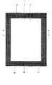
 図7は、本実施の形態3に係る真空断熱材の概略構成を模式的に示す正面図である。図8は、図7に示すA-A断面図である。図9は、図7に示す真空断熱材の封止部を拡大した断面図である。なお、図7においては、封止部をハッチングで示している。また、図8においては、真空断熱材(封止部)の一部を省略している。さらに、図9においては、第1熱溶着層及び第2熱溶着層の外面の一部を太線で表している。
[Configuration of vacuum insulation]
FIG. 7 is a front view schematically showing a schematic configuration of the vacuum heat insulating material according to the third embodiment. 8 is a cross-sectional view taken along line AA shown in FIG. FIG. 9 is an enlarged cross-sectional view of the sealing portion of the vacuum heat insulating material shown in FIG. In FIG. 7, the sealing portion is indicated by hatching. Moreover, in FIG. 8, a part of vacuum heat insulating material (sealing part) is abbreviate | omitted. Furthermore, in FIG. 9, a part of outer surface of the 1st heat welding layer and the 2nd heat welding layer is represented by the thick line.
 図7~図9に示すように、本実施の形態3に係る真空断熱材1は、実施の形態1に係る真空断熱材1と基本的構成は同じであるが、封止部8が波状に形成されている点が異なる。具体的には、封止部8は、熱溶着層5における第1熱溶着層5a側の外面のうねりの波高が、熱溶着層5における第2熱溶着層5b側の外面のうねりの波高よりも大きくなるように形成されている。 As shown in FIGS. 7 to 9, the vacuum heat insulating material 1 according to the third embodiment has the same basic configuration as the vacuum heat insulating material 1 according to the first embodiment, but the sealing portion 8 has a wave shape. It differs in that it is formed. Specifically, in the sealing portion 8, the wave height of the outer surface of the thermal welding layer 5 on the first thermal welding layer 5 a side is greater than the wave height of the outer surface of the thermal welding layer 5 on the second thermal welding layer 5 b side. Is also formed to be large.
 また、封止部8は、第1ラミネートフィルム4aから第2ラミネートフィルム4bに向かって凹むように形成されている第1凹部9aと、第2ラミネートフィルム4bから第1ラミネートフィルム4aに向かって凹むように形成されている第2凹部9bと、を有している。 Moreover, the sealing part 8 is dented toward the 1st laminate film 4a from the 1st recessed part 9a currently formed so that it may dent toward the 2nd laminate film 4b from the 1st laminate film 4a. A second recess 9b formed as described above.
 第1凹部9aと第2凹部9bは、交互に位置するように配置されている。換言すると、第1凹部9aと第2凹部9bは、真空断熱材1の厚み方向から見て、互いに直交する対向するように配置されていない。なお、本実施の形態3においては、各辺に沿って設けられた第1凹部9a(第2凹部9b)が直交するように配置したが、これに限定されず、これらの第1凹部9a(第2凹部9b)は、互いに交差しないように配置してもよい。また、本実施の形態3においては、4辺に沿って、第1凹部9a(第2凹部9b)を配置したが、これに限定されず、第1凹部9a(第2凹部9b)は、少なくとも1の辺に沿って配置されていればよく、例えば、3辺に沿って配置されていてもよい。 The first recesses 9a and the second recesses 9b are arranged so as to be alternately positioned. In other words, the first concave portion 9a and the second concave portion 9b are not disposed so as to face each other orthogonally when viewed from the thickness direction of the vacuum heat insulating material 1. In the third embodiment, the first concave portions 9a (second concave portions 9b) provided along the respective sides are arranged so as to be orthogonal to each other. However, the present invention is not limited to this, and the first concave portions 9a ( The second recesses 9b) may be arranged so as not to cross each other. In the third embodiment, the first recess 9a (second recess 9b) is arranged along the four sides. However, the present invention is not limited to this, and the first recess 9a (second recess 9b) is at least It may be arranged along one side, for example, may be arranged along three sides.
 また、第1凹部9aの第1熱溶着層5a側の外面51a(図9にて、太線で示す部分)の深さ(寸法)が、第2凹部9bの第2熱溶着層5b側の外面51b(図9にて、太線で示す部分)の深さ(寸法)よりも大きくなっている。換言すると、第1凹部9a及び第2凹部9bは、第1凹部9aにおける第1熱溶着層5aの外面51aの曲率半径が、第2凹部9bにおける第2熱溶着層5bの外面51bの曲率半径よりも小さくなるように形成されている。 Further, the depth (dimension) of the outer surface 51a (the portion indicated by a thick line in FIG. 9) of the first recess 9a on the first heat welding layer 5a side is the outer surface of the second recess 9b on the second heat welding layer 5b side. It is larger than the depth (dimension) of 51b (the portion indicated by the bold line in FIG. 9). In other words, in the first recess 9a and the second recess 9b, the radius of curvature of the outer surface 51a of the first heat-welded layer 5a in the first recess 9a is equal to the radius of curvature of the outer surface 51b of the second heat-welded layer 5b in the second recess 9b. It is formed to be smaller than that.
 なお、第1凹部9aと第2凹部9bの間隔は、ガスバリア層6a及びガスバリア層6bを劣化しない範囲で、任意に設定することができる。また、第1凹部9aと第2凹部9bは、一定の間隔となるように配置されてもよく、一定の間隔とならないように配置されてもよい。 In addition, the space | interval of the 1st recessed part 9a and the 2nd recessed part 9b can be arbitrarily set in the range which does not degrade the gas barrier layer 6a and the gas barrier layer 6b. Moreover, the 1st recessed part 9a and the 2nd recessed part 9b may be arrange | positioned so that it may become a fixed space | interval, and may be arrange | positioned so that it may not become a fixed space | interval.
 また、第1凹部9aの曲率半径と第2凹部9bの曲率半径は、ガスバリア層6a及びガスバリア層6bを劣化しない範囲で、任意に設定することができる。各第1凹部9aの曲率半径は、同一であってもよく、異なってもよい。同様に、各第2凹部9bの曲率半径は、同一であってもよく、異なってもよい。 Further, the radius of curvature of the first recess 9a and the radius of curvature of the second recess 9b can be arbitrarily set within a range not deteriorating the gas barrier layer 6a and the gas barrier layer 6b. The curvature radius of each 1st recessed part 9a may be the same, and may differ. Similarly, the curvature radius of each 2nd recessed part 9b may be the same, and may differ.
 そして、第1凹部9aにおける熱溶着層5の最深部には、熱溶着層5の厚みが最深部の周辺部よりも薄い薄肉部90aが形成されている。なお、薄肉部90aは、真空断熱材1内に気体又は水分が侵入することをより抑制する観点から、1つの辺に2箇所以上設けられていてもよく、本実施の形態4においては、1つの辺に4か所設けられている。 And in the deepest part of the heat welding layer 5 in the 1st recessed part 9a, the thin part 90a whose thickness of the heat welding layer 5 is thinner than the peripheral part of the deepest part is formed. Note that the thin-walled portion 90a may be provided at two or more locations on one side from the viewpoint of further suppressing gas or moisture from entering the vacuum heat insulating material 1. There are four places on one side.
 また、薄肉部90aは、第1熱溶着層5aと第2熱溶着層5bを充分に熱溶着させる観点から、真空断熱材1の外周近傍(例えば、真空断熱材1の外周から1~2mmの範囲)よりも内方に配置されてもよく、封止部8の内周20(図2参照)近傍(例えば、封止部8の内周20から1~2mmの範囲)よりも外方に配置されてもよい。さらに、各薄肉部90aにおける熱溶着層5の厚みは、同一であってもよく、同一でなくてもよい。 Further, the thin-walled portion 90a is provided in the vicinity of the outer periphery of the vacuum heat insulating material 1 (for example, 1 to 2 mm from the outer periphery of the vacuum heat insulating material 1 from the viewpoint of sufficiently heat-welding the first heat welding layer 5a and the second heat welding layer 5b. The inner periphery 20 (see FIG. 2) of the sealing portion 8 (for example, a range of 1 to 2 mm from the inner periphery 20 of the sealing portion 8). It may be arranged. Furthermore, the thickness of the heat welding layer 5 in each thin part 90a may be the same, and does not need to be the same.
 なお、ガスバリア層6a及びガスバリア層6bは、実施の形態1に係る真空断熱材1と同様に、両方とも金属箔で構成してもよく、実施の形態2に係る真空断熱材1と同様に、ガスバリア層6aを金属箔で構成し、ガスバリア層6bを蒸着フィルム層で構成してもよい。 Both the gas barrier layer 6a and the gas barrier layer 6b may be made of a metal foil, similarly to the vacuum heat insulating material 1 according to the first embodiment. Similarly to the vacuum heat insulating material 1 according to the second embodiment, The gas barrier layer 6a may be composed of a metal foil, and the gas barrier layer 6b may be composed of a vapor deposition film layer.
 [真空断熱材の製造方法]
 図10は、本実施の形態3に係る真空断熱材を製造する際に使用する第1加熱圧縮冶具の概略構成を模式的に示す断面図である。
[Method of manufacturing vacuum insulation]
FIG. 10 is a cross-sectional view schematically showing a schematic configuration of a first heating and compression jig used when manufacturing the vacuum heat insulating material according to the third embodiment.
 まず、図10を参照しながら、本実施の形態3に係る真空断熱材を製造する際に使用する第1加熱圧縮冶具について、説明する。 First, the first heat compression jig used when manufacturing the vacuum heat insulating material according to the third embodiment will be described with reference to FIG.
 図10に示すように、第1加熱圧縮冶具10は、金属製で、複数(ここでは、4つ)の突起部11を備えている。突起部11は、筋状に延設されていて、突起部11の先端部は、円弧状に形成されている。なお、隣接する突起部11の間隔は、任意に設定することができる。また、突起部11の先端部の曲率半径も、任意に設定することができる。 As shown in FIG. 10, the first heating and compression jig 10 is made of metal and includes a plurality of (here, four) protrusions 11. The protrusion 11 extends in a streak shape, and the tip of the protrusion 11 is formed in an arc shape. In addition, the space | interval of the adjacent projection part 11 can be set arbitrarily. Moreover, the curvature radius of the front-end | tip part of the projection part 11 can also be set arbitrarily.
 次に、本実施の形態3に係る真空断熱材1の製造方法の一例について、図7~図10を参照しながら説明する。 Next, an example of a method for manufacturing the vacuum heat insulating material 1 according to the third embodiment will be described with reference to FIGS.
 まず、矩形状の第1ラミネートフィルム4aと矩形状の第2ラミネートフィルム4bを作製し、第1ラミネートフィルム4aの第1熱溶着層5aと第2ラミネートフィルム4bの第2熱溶着層5bが互いに対向するように配置して、積層体を作製する。 First, a rectangular first laminate film 4a and a rectangular second laminate film 4b are prepared, and the first heat-welded layer 5a of the first laminate film 4a and the second heat-welded layer 5b of the second laminate film 4b are mutually connected. Arrange them so as to oppose each other to produce a laminate.
 次に、第1ラミネートフィルム4a及び第2ラミネートフィルム4bの周縁部の3辺を加熱しながら押圧して、第1熱溶着層5aと第2熱溶着層5bを熱溶着させて、袋状のラミネートフィルムを作製する。 Next, the three sides of the peripheral portions of the first laminate film 4a and the second laminate film 4b are pressed while being heated, so that the first heat-welded layer 5a and the second heat-welded layer 5b are heat-welded to form a bag-like shape. A laminate film is produced.
 このとき、第1加熱圧縮冶具10とシリコンゴムヒーター12(第2加熱圧縮冶具)とで第1ラミネートフィルム4a及び第2ラミネートフィルム4bの積層体を挟むようにして、加熱圧縮する。 At this time, the first heat-compressing jig 10 and the silicon rubber heater 12 (second heat-compressing jig) are heated and compressed so as to sandwich the laminate of the first laminated film 4a and the second laminated film 4b.
 具体的には、第1ラミネートフィルム4aの外面を第1加熱圧縮冶具10で加熱しながら押圧し、かつ、第2ラミネートフィルム4bの外面をシリコンゴムヒーター12で加熱しながら押圧する。これにより、第1熱溶着層5aと第2熱溶着層5bが熱溶着して、波状の封止部8が得られる。 Specifically, the outer surface of the first laminate film 4 a is pressed while being heated by the first heating and compression jig 10, and the outer surface of the second laminate film 4 b is pressed while being heated by the silicon rubber heater 12. Thereby, the 1st heat welding layer 5a and the 2nd heat welding layer 5b are heat-welded, and the wavelike sealing part 8 is obtained.
 ついで、袋状のラミネートフィルムの開口部から芯材2及び吸着剤3を挿入し、真空包装機を用いて、袋状のラミネートフィルム内部を真空引きしながら、開口部に位置する第1熱溶着層5aと第2熱溶着層5bを熱溶着して、真空断熱材1が得られる。 Next, the core material 2 and the adsorbent 3 are inserted from the opening of the bag-like laminate film, and the first heat welding located at the opening is evacuated while vacuuming the inside of the bag-like laminate film using a vacuum packaging machine. The vacuum heat insulating material 1 is obtained by thermally welding the layer 5a and the second heat welding layer 5b.
 ここで、第1ラミネートフィルム4aの外面を第1加熱圧縮冶具10で加熱押圧し、第2ラミネートフィルム4bの外面をシリコンゴムヒーター12で加熱押圧する理由は、以下の2つである。 Here, the outer surface of the first laminate film 4a is heated and pressed by the first heating and compression jig 10, and the outer surface of the second laminate film 4b is heated and pressed by the silicon rubber heater 12 for the following two reasons.
 一つは、波状の封止部8を形成する際に、密度の低い第1熱溶着層5aの方が、第1加熱圧縮冶具10の形状に沿って流動しやすいためである。もう一つは、密度の高い第2熱溶着層5bを有する第2ラミネートフィルム4bの外面を第1加熱圧縮冶具10で加熱押圧した場合、封止部8の端にエッジ切れが生じるおそれがあるためである。 One reason is that when the wave-shaped sealing portion 8 is formed, the first heat-welded layer 5a having a lower density is more likely to flow along the shape of the first heating and compression jig 10. The other is that when the outer surface of the second laminate film 4b having the high-density second heat-welding layer 5b is heated and pressed with the first heating and compression jig 10, the edge of the sealing portion 8 may be cut off. Because.
 なお、ここでは、第1加熱圧縮冶具10とシリコンゴムヒーター12を用いて、第1ラミネートフィルム4aと第2ラミネートフィルム4bの熱溶着と同時に、波状の封止部8を形成する形態を採用したが、これに限定されない。例えば、第1ラミネートフィルム4aと第2ラミネートフィルム4bを通常の平板冶具を用いて、薄肉部を有さない厚みが略均一な熱溶着層からなる封止部8を形成し、その後、封止部8上を第1加熱圧縮冶具10とシリコンゴムヒーター12で加熱圧縮して、封止部8を波状に形成してもよい。 Here, the first heat compression jig 10 and the silicon rubber heater 12 are used to form the wave-shaped sealing portion 8 simultaneously with the heat welding of the first laminate film 4a and the second laminate film 4b. However, it is not limited to this. For example, the first laminate film 4a and the second laminate film 4b are formed by using a normal flat plate jig to form the sealing portion 8 made of a heat-welded layer having a substantially uniform thickness without having a thin portion, and then sealing The sealing portion 8 may be formed in a wave shape by heating and compressing the portion 8 with the first heating and compression jig 10 and the silicon rubber heater 12.
 また、上述したように、4辺目の袋開口部を封止する際は、袋内部を減圧しながら密封するために、真空包装機を用いて封止する必要がある。 Also, as described above, when sealing the bag opening on the fourth side, it is necessary to use a vacuum packaging machine to seal the bag while reducing the pressure inside.
 通常の真空包装機は、平板状のヒートシール冶具が備わっていることから、袋開口部のみは真空包装機を用いて、第1ラミネートフィルム4aと第2ラミネートフィルム4bで構成された袋を封止すると、厚みが略均一な熱溶着層5からなる封止部8が形成される。このため、4辺目に封止部8を形成した後に、第1加熱圧縮冶具10とシリコンゴムヒーター12で加熱圧縮して、当該封止部8を波状に形成してもよい。 Since a normal vacuum packaging machine is equipped with a flat heat seal jig, only the bag opening is sealed with a vacuum packaging machine to seal the bag composed of the first laminate film 4a and the second laminate film 4b. If it stops, the sealing part 8 which consists of the heat welding layer 5 with a substantially uniform thickness will be formed. For this reason, after forming the sealing part 8 in the 4th side, it heat-compresses with the 1st heating compression jig 10 and the silicon rubber heater 12, and the said sealing part 8 may be formed in a wave shape.
 [真空断熱材の作用効果]
 このように構成された本実施の形態3に係る真空断熱材1では、封止部8の熱溶着層5に他の部分よりも厚みが小さい薄肉部90aが形成されている。このため、薄肉部90aでは、第1ラミネートフィルム4a又は第2ラミネートフィルム4bの端面から侵入する気体及び水分の透過面積が縮小される。これにより、気体及び水分の透過抵抗が増大し、気体及び水分の透過速度が低減されることから、経時的に透過する気体及び水分量が抑制され、真空断熱材1は、長期にわたって優れた密封性能を発揮できる。
[Effects of vacuum insulation]
In the vacuum heat insulating material 1 according to the third embodiment configured as described above, a thin-walled portion 90 a having a smaller thickness than other portions is formed in the heat-welded layer 5 of the sealing portion 8. For this reason, in the thin part 90a, the permeation | transmission area of the gas which penetrate | invades from the end surface of the 1st laminate film 4a or the 2nd laminate film 4b, and a water | moisture content is reduced. Thereby, the permeation resistance of gas and moisture is increased and the permeation rate of gas and moisture is reduced, so that the amount of gas and moisture that permeate over time is suppressed, and the vacuum heat insulating material 1 is excellent in sealing over a long period of time. Performance can be demonstrated.
 また、本実施の形態3に係る真空断熱材1では、封止部8が波状に形成されていて、円弧状の第1凹部9a及び第2凹部9bを有している。このため、ガスバリア層6a及びガスバリア層6bが円弧状に曲がり、角部が形成されにくいため、ガスバリア層6a及びガスバリア層6bでクラックの発生が極めて起きにくくなる。 Further, in the vacuum heat insulating material 1 according to the third embodiment, the sealing portion 8 is formed in a wave shape and has the arc-shaped first concave portion 9a and the second concave portion 9b. For this reason, since the gas barrier layer 6a and the gas barrier layer 6b are bent in an arc shape and corner portions are hardly formed, cracks are hardly generated in the gas barrier layer 6a and the gas barrier layer 6b.
 ところで、熱溶着層5の薄肉部90aにおいては、熱溶着層5の厚みが周辺部よりも薄くなり、その厚み減少分だけ強度が低下する。しかしながら、本実施の形態3に係る真空断熱材1では、封止部8が、封止部8が波状に形成されていて、円弧状の第1凹部9a及び第2凹部9bを有しているので、熱溶着層5の厚みが連続的に滑らかに増減している。 By the way, in the thin-walled portion 90a of the heat-welded layer 5, the thickness of the heat-welded layer 5 becomes thinner than the peripheral portion, and the strength is reduced by the thickness reduction. However, in the vacuum heat insulating material 1 according to the third embodiment, the sealing portion 8 includes the first concave portion 9a and the second concave portion 9b in which the sealing portion 8 is formed in a wave shape. Therefore, the thickness of the heat welding layer 5 continuously increases and decreases smoothly.
 このため、封止部8の強度(曲げ強度など)も位置が変わるにつれて連続的に滑らかに増減することから、熱溶着層5の薄肉部90aにおいて局所的に外力が集中することが起きにくい。これにより、熱溶着層5の薄肉部90a及びその近傍におけるクラックの発生、及び封止部8の破断が極めて起きにくくなる。 For this reason, since the strength (bending strength, etc.) of the sealing portion 8 also increases and decreases continuously and smoothly as the position changes, it is difficult for external forces to concentrate locally in the thin portion 90a of the heat-welded layer 5. Thereby, generation | occurrence | production of the crack in the thin part 90a of the heat welding layer 5 and its vicinity, and the fracture | rupture of the sealing part 8 become very difficult to occur.
 以上により、本実施の形態3に係る真空断熱材1では、熱溶着層5の薄肉部90a及びその近傍において、クラックの発生が起きにくく、及び封止部8の破断が極めて起きにくい。このため、本実施の形態3に係る真空断熱材1は、長期に渡って優れた断熱性能を維持することができる。 As described above, in the vacuum heat insulating material 1 according to the third embodiment, the occurrence of cracks hardly occurs in the thin-walled portion 90a of the heat-welded layer 5 and the vicinity thereof, and the fracture of the sealing portion 8 hardly occurs. For this reason, the vacuum heat insulating material 1 which concerns on this Embodiment 3 can maintain the heat insulation performance excellent over the long term.
 ところで、薄肉部90a及びその近傍では、熱溶着層5よりも外側にある第1ラミネートフィルム4aの第1熱溶着層5a及びガスバリア層6bと、第2ラミネートフィルム4bの第2熱溶着層5b及びガスバリア層6bが、熱溶着層5の形状に沿って歪曲することによる応力を受け、第1ラミネートフィルム4a及び第2ラミネートフィルム4bの強度が低下するおそれがある。 By the way, in the thin part 90a and its vicinity, the 1st heat welding layer 5a and the gas barrier layer 6b of the 1st laminate film 4a which are outside the heat welding layer 5, and the 2nd heat welding layer 5b of the 2nd laminate film 4b and The gas barrier layer 6b receives stress due to distortion along the shape of the heat-welded layer 5, and the strength of the first laminate film 4a and the second laminate film 4b may be reduced.
 しかしながら、本実施の形態3に係る真空断熱材1では、封止部8が、熱溶着層5における第1熱溶着層5a側の外面のうねりの波高が、熱溶着層5における第2熱溶着層5b側の外面のうねりの波高よりも大きくなるように形成されている。 However, in the vacuum heat insulating material 1 according to the third embodiment, the sealing portion 8 has a wave height of the undulation of the outer surface of the thermal welding layer 5 on the first thermal welding layer 5a side, so that the second thermal welding in the thermal welding layer 5 is performed. It is formed to be larger than the wave height of the undulation on the outer surface on the layer 5b side.
 このため、封止部8における、第2ラミネートフィルム4b側の強度低下は、第1ラミネートフィルム4a側の強度低下に比べて僅かとなる。これにより、封止部8では、第2ラミネートフィルム4bが第2ラミネートフィルム4bを支持する形で剛性が保たれる。したがって、真空断熱材1が外力を受けても、熱溶着層5の薄肉部90a及びその近傍におけるクラックの発生、及び封止部8の破断が極めて起きにくくなる。 For this reason, the strength reduction on the second laminate film 4b side in the sealing portion 8 is slightly smaller than the strength reduction on the first laminate film 4a side. Thereby, in the sealing part 8, rigidity is maintained in the form in which the second laminate film 4b supports the second laminate film 4b. Therefore, even if the vacuum heat insulating material 1 receives an external force, generation of cracks in the thin-walled portion 90a of the heat-welded layer 5 and the vicinity thereof, and breakage of the sealing portion 8 are hardly caused.
 また、本実施の形態3に係る真空断熱材1では、真空断熱材1の厚み方向から見て、第1凹部9aと第2凹部9bが対向しないように配置されている。このため、凹部が対抗するように配置されている特許文献1の真空断熱パネルに比して、封止部8の歪曲による強度低下を抑制することができる。また、封止部8が外力を受けた際に封止部8に傷が極めてつきにくく、封止部8の破断が極めて起きにくくなると同時に、第1凹部9aにおけるガスバリア層6a又は第2凹部9bにおけるガスバリア層6bのクラックの発生をより抑制することができる。 Further, in the vacuum heat insulating material 1 according to the third embodiment, the first concave portion 9a and the second concave portion 9b are arranged so as not to face each other when viewed from the thickness direction of the vacuum heat insulating material 1. For this reason, compared with the vacuum heat insulation panel of patent document 1 arrange | positioned so that a recessed part may oppose, the strength fall by distortion of the sealing part 8 can be suppressed. Further, when the sealing portion 8 receives an external force, the sealing portion 8 is hardly damaged, and the sealing portion 8 is hardly broken. At the same time, the gas barrier layer 6a or the second recess 9b in the first recess 9a. The generation of cracks in the gas barrier layer 6b can be further suppressed.
 さらに、本実施の形態3に係る真空断熱材1では、真空断熱材1の外周の1辺に薄肉部90aが2個以上形成されていてもよい。 Furthermore, in the vacuum heat insulating material 1 according to Embodiment 3, two or more thin portions 90 a may be formed on one side of the outer periphery of the vacuum heat insulating material 1.
 薄肉部90aにおいては、封止部8の他箇所に比べて熱溶着層5の厚みが薄く、シール強度が低下することにより、例えば、製造工程において、芯材2を構成するガラス繊維又はシリカ粉末等を挟み込んだ状態で、ラミネートフィルムが熱溶着された場合、薄肉部90aにおいて熱溶着不良が発生することが懸念される。 In the thin-walled portion 90a, the thickness of the heat-welded layer 5 is thinner than that of other portions of the sealing portion 8 and the sealing strength is reduced. For example, in the manufacturing process, glass fiber or silica powder constituting the core material 2 When the laminate film is heat-welded in a state in which, for example, is sandwiched, there is a concern that heat-welding failure may occur in the thin portion 90a.
 熱溶着不良が発生した箇所では樹脂が存在しないため、ガス侵入抑制効果が低下する。この対策として、少なくとも2個以上の薄肉部90aを設けることにより、熱溶着不良に起因する真空断熱材1内部への気体及び水分侵入促進の影響が緩和される。 Since there is no resin at locations where thermal welding defects have occurred, the effect of suppressing gas penetration is reduced. As a countermeasure, by providing at least two or more thin-walled portions 90a, the influence of gas and moisture penetration into the vacuum heat insulating material 1 due to poor heat welding is mitigated.
 特に、芯材2としてガラス繊維を用いた場合は、挟雑物として熱溶着の際に挟み込まれた芯材2が加熱変形し、薄肉部90aにスルーホールを形成することが多々あることから、本発明の(本実施の形態の)効果がより顕著となる。 In particular, when glass fiber is used as the core material 2, the core material 2 sandwiched during thermal welding as an interstitial material is often deformed by heating, and a through hole is often formed in the thin portion 90a. The effect (of the present embodiment) of the present invention becomes more remarkable.
 また、薄肉部90aにおいては、ラミネートフィルムの強度が周囲部よりも低くなり、外力を受けた際の荷重集中が懸念されるが、薄肉部90aが複数個存在することにより、外力の荷重が分散され、薄肉部90aにおけるクラックの発生及び封止部8の破断が極めて起きにくくなる。 Further, in the thin portion 90a, the strength of the laminate film is lower than that of the surrounding portion, and there is a concern about load concentration when receiving an external force. However, due to the presence of a plurality of thin portions 90a, the load of the external force is dispersed. Thus, the occurrence of cracks in the thin portion 90a and the breakage of the sealing portion 8 are extremely difficult to occur.
 さらに、薄肉部90aを複数個有する場合は、薄肉部90aが1個のみの場合と比べて、薄肉部90aにおける熱溶着層5の厚みを増加させても、同一の効果が得られる。このため、薄肉部90aにおける熱溶着層5の厚みを増加させることにより、ラミネートフィルムの強度及びシール強度低下が緩和され、薄肉部90aにおけるクラックの発生及び封止部8の破断のリスクが低減することができる。 Furthermore, in the case where a plurality of thin portions 90a are provided, the same effect can be obtained even if the thickness of the heat welding layer 5 in the thin portions 90a is increased as compared with the case where there is only one thin portion 90a. For this reason, by increasing the thickness of the heat-welded layer 5 in the thin-walled portion 90a, the decrease in the strength and sealing strength of the laminate film is alleviated, and the risk of occurrence of cracks in the thin-walled portion 90a and breakage of the sealing portion 8 is reduced. be able to.
 また、本実施の形態3に係る真空断熱材1の製造方法では、先端部が円弧状に形成されている突起部を備える第1加熱圧縮冶具を用いて、第1ラミネートフィルム4aを加熱圧縮する。このため、加圧による外力が突起部11の円弧の接線と垂直な方向にも加わることにより、熱溶着層5の樹脂が薄肉部90aの両端方向へ流動しやすくなる。 Moreover, in the manufacturing method of the vacuum heat insulating material 1 which concerns on this Embodiment 3, the 1st laminated film 4a is heat-compressed using the 1st heating compression jig provided with the projection part in which the front-end | tip part is formed in circular arc shape. . For this reason, the external force by pressurization is also applied in the direction perpendicular to the tangent line of the arc of the protrusion 11, so that the resin of the heat-welded layer 5 easily flows in the both ends of the thin portion 90 a.
 したがって、薄肉部90aの厚みが同じの真空断熱材1を作成する場合に、特許文献1に開示されている封止用治具106のような平面部にて圧縮される場合と比べて、温度条件及び圧力条件を緩和することができる。これにより、第1ラミネートフィルム4a及び第2ラミネートフィルム4bの劣化を抑制することができる。 Therefore, when producing the vacuum heat insulating material 1 with the same thickness of the thin-walled portion 90a, the temperature is lower than when compressed by a flat portion such as the sealing jig 106 disclosed in Patent Document 1. Conditions and pressure conditions can be relaxed. Thereby, deterioration of the 1st laminate film 4a and the 2nd laminate film 4b can be controlled.
 言い換えれば、同一の成形条件によって、より熱溶着層5の薄肉部90aの厚みを薄くすることが可能となり、第1ラミネートフィルム4a又は第2ラミネートフィルム4bの端面からの気体及び水分侵入量の抑制がより容易となる。 In other words, it becomes possible to further reduce the thickness of the thin portion 90a of the heat-welded layer 5 under the same molding conditions, and suppress the amount of gas and moisture intrusion from the end face of the first laminate film 4a or the second laminate film 4b. Becomes easier.
 (実施の形態4)
 本実施の形態4に係る断熱箱体は、実施の形態1~3のいずれかの真空断熱材と、外箱と、内箱と、を備え、真空断熱材は、第1ラミネート又は第2ラミネートの外面が内箱における外箱と対向する面に固定されるように配置され、外箱と内箱との間の真空断熱材が配置されている部分を除いた残りの空間に発泡断熱材が充填されている。
(Embodiment 4)
A heat insulating box according to the fourth embodiment includes the vacuum heat insulating material according to any one of the first to third embodiments, an outer box, and an inner box, and the vacuum heat insulating material is the first laminate or the second laminate. The outer surface of the inner box is fixed to the surface facing the outer box in the inner box, and the foam insulation is in the remaining space excluding the portion where the vacuum heat insulating material is disposed between the outer box and the inner box. Filled.
 以下、本実施の形態4に係る断熱箱体の一例について、図11~図13を参照しながら説明する。 Hereinafter, an example of the heat insulation box according to the fourth embodiment will be described with reference to FIGS.
 [断熱箱体の構成]
 図11は、本実施の形態4に係る断熱箱体の概略構成を模式的に示す斜視図である。図12は、図11に示B-B断面図である。図13は、図11に示すC-C断面図である。
[Configuration of heat insulation box]
FIG. 11 is a perspective view schematically showing a schematic configuration of the heat insulating box according to the fourth embodiment. 12 is a cross-sectional view taken along the line BB in FIG. 13 is a cross-sectional view taken along the line CC shown in FIG.
 図11~図13に示すように、本実施の形態4に係る断熱箱体21は、上記実施の形態1~3のいずれかの真空断熱材1と、前方に開口を有する金属製(例えば、鉄板又は鋼板等)の外箱27と、硬質樹脂製(例えば、ABS)の内箱28と、外箱27と内箱28の間に発泡充填された発泡断熱材29と、を備えている。 As shown in FIGS. 11 to 13, the heat insulating box 21 according to the fourth embodiment includes a vacuum heat insulating material 1 according to any of the first to third embodiments and a metal having an opening in the front (for example, An outer box 27 of iron plate or steel plate, an inner box 28 made of hard resin (for example, ABS), and a foam heat insulating material 29 filled between the outer box 27 and the inner box 28 by foaming.
 真空断熱材1は、外箱27の天面、背面、左側面、及び右側面の内側に接して貼り付けられている。また、真空断熱材1は、内箱28の底面に接して貼り付けられている。なお、真空断熱材1の気体吸着剤は、中心よりも庫外側(外箱側)に配設されている。 The vacuum heat insulating material 1 is attached in contact with the top, back, left side, and right side of the outer box 27. The vacuum heat insulating material 1 is attached in contact with the bottom surface of the inner box 28. In addition, the gas adsorbent of the vacuum heat insulating material 1 is arrange | positioned rather than the center at the warehouse outer side (outer box side).
 断熱箱体21の内部空間には、第1断熱仕切り部30~第4断熱仕切り部33により、複数の貯蔵室に区画されている。具体的には、断熱箱体21の上部には、冷蔵室22が設けられていて、冷蔵室22の下方には、上段冷凍室23と製氷室24が横並びに設けられている。そして、冷蔵室22と上段冷凍室23及び製氷室24を区画するように、第1断熱仕切り部30が設けられていて、上段冷凍室23と製氷室24を区画するように、第2断熱仕切り部31が設けられている。 The internal space of the heat insulation box 21 is partitioned into a plurality of storage chambers by the first heat insulation partition 30 to the fourth heat insulation partition 33. Specifically, a refrigerating room 22 is provided above the heat insulating box 21, and an upper freezing room 23 and an ice making room 24 are provided side by side below the refrigerating room 22. And the 1st heat insulation partition part 30 is provided so that the refrigerator compartment 22 and the upper stage freezing room 23, and the ice making room 24 may be divided, and a 2nd heat insulation partition so that the upper stage freezing room 23 and the ice making room 24 may be divided. A part 31 is provided.
 また、上段冷凍室23と製氷室24の下方には、下段冷凍室25が設けられていて、下段冷凍室25の下方には、野菜室26が設けられている。そして、上段冷凍室23及び製氷室24と下段冷凍室25を区画するように、第3断熱仕切り部32が設けられていて、下段冷凍室25と野菜室26を区画するように、第4断熱仕切り部33が設けられている。 Further, a lower freezer room 25 is provided below the upper freezer room 23 and the ice making room 24, and a vegetable room 26 is provided below the lower freezer room 25. And the 3rd heat insulation partition part 32 is provided so that the upper stage freezing room 23 and the ice making room 24, and the lower stage freezing room 25 may be divided, and the 4th heat insulation so that the lower stage freezing room 25 and the vegetable compartment 26 may be divided. A partition part 33 is provided.
 第2断熱仕切り部31及び第3断熱仕切り部32は、外箱27及び内箱28の間に発泡断熱材29を発泡させた後に、組み立てられる部品であるため、仕切り部の断熱材として、発泡ポリスチレンが使われるが、これに限定されない。例えば、断熱性能及び剛性を向上させる観点から、発泡断熱材29を用いてもよい。また、例えば、断熱性能及び剛性を向上させ、仕切り部のさらなる薄型化を図る観点から、本実施の形態1~4のいずれかの真空断熱材1を用いてもよい。 Since the second heat insulating partition part 31 and the third heat insulating partition part 32 are parts that are assembled after foaming the foam heat insulating material 29 between the outer box 27 and the inner box 28, foam is used as the heat insulating material for the partition part. Polystyrene is used, but is not limited to this. For example, you may use the foam heat insulating material 29 from a viewpoint of improving heat insulation performance and rigidity. Further, for example, from the viewpoint of improving the heat insulating performance and rigidity and further reducing the thickness of the partition portion, the vacuum heat insulating material 1 according to any of Embodiments 1 to 4 may be used.
 また、ドアフレームの稼動部を確保して、第2断熱仕切り部31及び第3断熱仕切り部32の形状の薄型化又は廃止を行うことで、冷却風路を確保でき、断熱箱体21の冷却能力の向上を図ることもできる。また、第2断熱仕切り部31及び第3断熱仕切り部32の内部をくりぬき、冷却風路とすることで、材料の低減につながる。 In addition, by securing the operating part of the door frame and thinning or eliminating the shape of the second heat insulating partition part 31 and the third heat insulating partition part 32, a cooling air passage can be secured and the heat insulating box body 21 is cooled. You can also improve your ability. Moreover, the inside of the 2nd heat insulation partition part 31 and the 3rd heat insulation partition part 32 is hollowed, and it leads to reduction of material by setting it as a cooling air path.
 また、上段冷凍室23、製氷室24、下段冷凍室25、及び野菜室26には、それぞれ、レール等を有する引き出し式の扉(いずれも図示せず)が設けられている。冷蔵室22の前面には、例えば、観音開き式の扉(図示せず)が設けられている。 In addition, each of the upper freezing room 23, the ice making room 24, the lower freezing room 25, and the vegetable room 26 is provided with a drawer-type door (not shown) having rails and the like. On the front surface of the refrigerator compartment 22, for example, a double door (not shown) is provided.
 冷蔵室22は、冷蔵保存のために、食品等が凍らない温度を下限に、通常1~5℃で設定されている。野菜室26は、冷蔵室22と同等もしくは若干高い温度である2℃~7℃で設定されていることが多い。低温にすれば、葉野菜の鮮度を長期間維持することが可能となる。上段冷凍室23と下段冷凍室25は、冷凍保存のために、通常-22~-18℃で設定されているが、冷凍保存状態の向上のために、例えば、-30~-25℃の低温で設定されることもある。 The refrigerator compartment 22 is normally set at 1 to 5 ° C., with the lower limit of the temperature at which the food is not frozen for refrigerated storage. The vegetable room 26 is often set at 2 ° C. to 7 ° C., which is equal to or slightly higher than that of the refrigerator room 22. If the temperature is lowered, the freshness of the leafy vegetables can be maintained for a long time. The upper freezer compartment 23 and the lower freezer compartment 25 are usually set at −22 to −18 ° C. for cryopreservation. However, in order to improve the frozen preservation state, for example, a low temperature of −30 to −25 ° C. It may be set by.
 冷蔵室22及び野菜室26は庫内をプラス温度で設定されるので、冷蔵温度帯を呼ばれる。また、上段冷凍室23、下段冷凍室25、及び製氷室24は、庫内をマイナス温度で設定されるので、冷凍温度帯を呼ばれる。なお、上段冷凍室23は、切替室として、冷蔵温度帯から冷凍温度帯まで選択可能な部屋としてもよい。 Refrigerated room 22 and vegetable room 26 are called refrigerated temperature zones because the interior is set at a plus temperature. Moreover, since the upper stage freezer room 23, the lower stage freezer room 25, and the ice making room 24 are set by the minus temperature in the store | warehouse | chamber, they are called freezing temperature zones. In addition, the upper freezer compartment 23 is good also as a room which can be selected from a refrigerating temperature zone to a freezing temperature zone as a switching room.
 断熱箱体21の天面部は、図12に示すように、断熱箱体21の背面方向に向かって階段状に形成されていて、第1天面部35と第2天面部36を有している。第2天面部36には、機械室34が設けられていて、機械室34には、圧縮機37及び水分除去を行うドライヤ(図示せず)等の冷却サイクルを構成する部品(機器)が収容されている。 As shown in FIG. 12, the top surface portion of the heat insulation box body 21 is formed in a step shape toward the back surface of the heat insulation box body 21, and has a first top surface portion 35 and a second top surface portion 36. . The second top surface portion 36 is provided with a machine room 34. The machine room 34 accommodates components (equipment) constituting a cooling cycle such as a compressor 37 and a dryer (not shown) for removing moisture. Has been.
 冷却サイクルは、圧縮機37、ドライヤ、コンデンサ(図示せず)、放熱用の放熱パイプ、キャピラリーチューブ38、及び冷却器39で構成されている。該冷却サイクルには、冷媒が封入されていて、冷却運転が行われる。なお、冷媒には、近年、環境保護のために可燃性冷媒を用いることが多い。また、三方弁又は切替弁を用いる冷却サイクルの場合には、それらの機能部品を機械室34内に配設されていてもよい。 The cooling cycle includes a compressor 37, a dryer, a condenser (not shown), a heat radiating pipe, a capillary tube 38, and a cooler 39. In the cooling cycle, a refrigerant is enclosed and a cooling operation is performed. In recent years, a flammable refrigerant is often used as a refrigerant for environmental protection. Further, in the case of a cooling cycle using a three-way valve or a switching valve, those functional components may be disposed in the machine room 34.
 断熱箱体21の背面には、上下方向に縦長に延びる冷却室40が設けられている。具体的には、冷却室40は、上段冷凍室23及び製氷室24と下段冷凍室25の後方に配設されている。冷却室40内には、フィンアンドチューブ式の冷気を生成する冷却器39が配設されている。なお、冷却器39の材質は、アルミ又は銅が用いられる。 A cooling chamber 40 extending vertically in the vertical direction is provided on the back surface of the heat insulating box 21. Specifically, the cooling chamber 40 is disposed behind the upper freezing chamber 23, the ice making chamber 24, and the lower freezing chamber 25. In the cooling chamber 40, a cooler 39 that generates fin-and-tube cold air is disposed. The material of the cooler 39 is aluminum or copper.
 冷却器39の近傍(例えば、上部空間)には、強制対流方式により、冷蔵室22、上段冷凍室23及び製氷室24、下段冷凍室25、並びに野菜室26の各貯蔵室に冷却器39で生成した冷気を送風する冷気送風ファン41が配置されている。 In the vicinity of the cooler 39 (for example, the upper space), the refrigerator 39 is connected to each storage room of the refrigerating room 22, the upper freezing room 23, the ice making room 24, the lower freezing room 25, and the vegetable room 26 by a forced convection method. A cold air blowing fan 41 for blowing the generated cold air is disposed.
 また、冷却器39の下部空間には、ガラス管製のラジアントヒータ42が設けられている。ラジアントヒータ42は、冷却時に冷却器39又は冷気送風ファン41に付着する霜を除霜する除霜装置として機能する。なお、除霜装置は、特に指定するものではなく、ラジアントヒータの他に、冷却器39に密着したパイプヒータを用いてもよい。 In the lower space of the cooler 39, a radiant heater 42 made of glass tube is provided. The radiant heater 42 functions as a defrosting device that defrosts frost adhering to the cooler 39 or the cold air blowing fan 41 during cooling. The defroster is not particularly specified, and a pipe heater that is in close contact with the cooler 39 may be used in addition to the radiant heater.
 なお、冷気送風ファン41は、内箱28に直接配設されることもあるが、これに限定されない。例えば、冷気送風ファン41を発泡後に組み立てられる第2断熱仕切り部31に配設し、部品のブロック加工を行うことで、製造コストの低減を図ることもできる。 In addition, although the cool air ventilation fan 41 may be directly arrange | positioned in the inner box 28, it is not limited to this. For example, it is possible to reduce the manufacturing cost by disposing the cool air blowing fan 41 in the second heat insulating partition 31 assembled after foaming and performing block processing of the parts.
 次に、断熱箱体21の冷却について説明する。なお、圧縮機37の運転は、図示されない制御器によって、制御されている。 Next, cooling of the heat insulation box 21 will be described. The operation of the compressor 37 is controlled by a controller (not shown).
 まず、例えば、扉の開閉等により、冷蔵室22等に外気が入り、断熱箱体21内部の温度が上昇して冷凍室センサ(図示せず)が、起動温度以上になった場合に、圧縮機37が起動し、冷却運転が開始される。 First, for example, when the outside air enters the refrigerating chamber 22 or the like by opening or closing the door, the temperature inside the heat insulating box 21 rises, and the freezing chamber sensor (not shown) becomes the starting temperature or higher, compression is performed. The machine 37 is activated and the cooling operation is started.
 圧縮機37から吐出された高温高圧の冷媒は、最終的に機械室34に配置されたドライヤ(図示せず)まで到達する間、特に外箱27に設置される放熱パイプにおいて、外箱27の外側の空気及び断熱箱体21内部の発泡断熱材29との熱交換により、冷却されて液化する。液化した冷媒は、キャピラリーチューブ38に供給される。 While the high-temperature and high-pressure refrigerant discharged from the compressor 37 finally reaches a dryer (not shown) disposed in the machine chamber 34, particularly in a heat radiating pipe installed in the outer box 27, It is cooled and liquefied by heat exchange with the outside air and the foam heat insulating material 29 inside the heat insulating box 21. The liquefied refrigerant is supplied to the capillary tube 38.
 キャピラリーチューブ38に供給された冷媒は、キャピラリーチューブ38で減圧されて、冷却器39に流入し、冷却器39周辺の空気と熱交換して、気化する。これにより、冷却器39周辺の空気が冷却され、冷却された空気(冷気)は、冷気送風ファン41により、冷蔵室22等に供給され、断熱箱体21内部を冷却する。 The refrigerant supplied to the capillary tube 38 is decompressed by the capillary tube 38, flows into the cooler 39, exchanges heat with the air around the cooler 39, and vaporizes. Thereby, the air around the cooler 39 is cooled, and the cooled air (cold air) is supplied to the refrigerating chamber 22 and the like by the cold air blowing fan 41 to cool the inside of the heat insulating box 21.
 気化した冷媒は、圧縮機37に戻り、圧縮機37により圧縮されて、吐出され、冷却サイクル内を循環する。そして、断熱箱体21内が冷却されて、冷凍室センサ(図示せず)の温度が停止温度以下になった場合に、圧縮機37の運転が停止される。 The vaporized refrigerant returns to the compressor 37, is compressed by the compressor 37, is discharged, and circulates in the cooling cycle. And when the inside of the heat insulation box 21 is cooled and the temperature of the freezer compartment sensor (not shown) becomes below the stop temperature, the operation of the compressor 37 is stopped.
 このように構成された、本実施の形態4に係る断熱箱体21は、実施の形態1~3のいずれかの真空断熱材1を備えているため、実施の形態1~3のいずれかの真空断熱材1と同様の作用効果を奏する。 Since the heat insulating box 21 according to the fourth embodiment configured as described above includes the vacuum heat insulating material 1 according to any one of the first to third embodiments, any one of the first to third embodiments. The same effect as the vacuum heat insulating material 1 is produced.
 上記説明から、当業者にとっては、本発明の多くの改良や他の実施形態が明らかである。したがって、上記説明は、例示としてのみ解釈されるべきであり、本発明を実行する最良の態様を当業者に教示する目的で提供されたものである。本発明の要旨を逸脱することなく、その構造及び/又は機能の詳細を実質的に変更できる。また、上記実施形態に開示されている複数の構成要素の適宜な組合せにより種々の発明を形成できる。 From the above description, many modifications and other embodiments of the present invention are apparent to persons skilled in the art. Accordingly, the foregoing description should be construed as illustrative only and is provided for the purpose of teaching those skilled in the art the best mode of carrying out the invention. The details of the structure and / or function may be substantially changed without departing from the scope of the invention. Moreover, various inventions can be formed by appropriately combining a plurality of constituent elements disclosed in the embodiment.
 本発明の真空断熱材、それを備える断熱箱体、及び真空断熱材の製造方法は、夾雑物シール性とガスバリア性を改善することができるため、冷蔵庫等の分野で有用である。 The vacuum heat insulating material of the present invention, the heat insulating box including the same, and the method for manufacturing the vacuum heat insulating material can improve the sealing property of foreign substances and the gas barrier property, and thus are useful in the field of refrigerators and the like.
 1 真空断熱材
 2 芯材
 3 吸着剤
 4a 第1ラミネートフィルム
 4b 第2ラミネートフィルム
 5a 第1熱溶着層
 5b 第2熱溶着層
 6a ガスバリア層
 6b ガスバリア層
 7 熱溶着層
 7a 表面保護層
 7b 表面保護層
 8 封止部
 9a 第1凹部
 9b 第2凹部
 10 第1加熱圧縮冶具
 11 突起部
 12 シリコンゴムヒーター
 20 内周
 21 断熱箱体
 22 冷蔵室
 23 上段冷凍室
 24 製氷室
 25 下段冷凍室
 26 野菜室
 27 外箱
 28 内箱
 29 発泡断熱材
 30 第1断熱仕切り部
 31 第2断熱仕切り部
 32 第3断熱仕切り部
 33 第4断熱仕切り部
 34 機械室
 35 第1天面部
 36 第2天面部
 37 圧縮機
 38 キャピラリーチューブ
 39 冷却器
 40 冷却室
 41 冷気送風ファン
 42 ラジアントヒータ
 51a 外面
 51b 外面
 70a フィルム
 70b フィルム
 71a フィルム
 71b フィルム
 80b 基材
 81b 基材
 90a 薄肉部
 90b 蒸着膜
 91b 蒸着膜
 101 真空断熱パネル
 102 ガスバリア層
 103 接着層
 104 外被体
 105 薄肉条部
 106 封止用治具
 107 角部


DESCRIPTION OF SYMBOLS 1 Vacuum heat insulating material 2 Core material 3 Adsorbent 4a 1st laminate film 4b 2nd laminate film 5a 1st heat welding layer 5b 2nd heat welding layer 6a Gas barrier layer 6b Gas barrier layer 7 Heat welding layer 7a Surface protection layer 7b Surface protection layer DESCRIPTION OF SYMBOLS 8 Sealing part 9a 1st recessed part 9b 2nd recessed part 10 1st heating compression jig 11 Protrusion part 12 Silicon rubber heater 20 Inner periphery 21 Heat insulation box 22 Refrigeration room 23 Upper stage freezing room 24 Ice making room 25 Lower stage freezing room 26 Vegetable room 27 Outer box 28 Inner box 29 Foam heat insulating material 30 First heat insulating partition portion 31 Second heat insulating partition portion 32 Third heat insulating partition portion 33 Fourth heat insulating partition portion 34 Machine room 35 First top surface portion 36 Second top surface portion 37 Compressor 38 Capillary tube 39 Cooler 40 Cooling chamber 41 Cold air blowing fan 42 Radiant heater 51a outer surface 51b outer surface 70 Film 70b Film 71a film 71b film 80b substrate 81b substrates 90a thin portion 90b deposited film 91b deposited film 101 vacuum insulation panels 102 gas barrier layer 103 adhesive layer 104 enveloping body 105 thin strip portion 106 sealing jig 107 corner

Claims (8)

  1.  無機繊維を含む芯材と、
     内面に第1熱溶着層を有する第1ラミネートフィルムと、
     内面に第2熱溶着層を有する第2ラミネートフィルムと、を備え、
     前記第1熱溶着層の密度が前記第2熱溶着層の密度よりも小さいことを特徴とする、真空断熱材。
    A core material containing inorganic fibers;
    A first laminate film having a first heat-welded layer on the inner surface;
    A second laminate film having a second heat-welded layer on the inner surface,
    The vacuum heat insulating material, wherein the density of the first heat welding layer is smaller than the density of the second heat welding layer.
  2.  前記第1ラミネートフィルムは金属箔を有し、前記第2ラミネートフィルムは蒸着膜を有することを特徴とする、請求項1に記載の真空断熱材。 The vacuum heat insulating material according to claim 1, wherein the first laminate film has a metal foil, and the second laminate film has a deposited film.
  3.  前記真空断熱材には、前記芯材が減圧状態で密封されるように、前記第1熱溶着層における周縁部の内面と前記第2熱溶着層における周縁部の内面が互いに熱溶着された熱溶着層を有する封止部が設けられており、
     前記封止部は、前記第1熱溶着層の外面のうねりの波高が、前記第2熱溶着層の外面のうねりの波高よりも大きくなるように、波状に形成されていて、前記第1ラミネートフィルムから前記第2ラミネートフィルムに向かって凹むように形成されている第1凹部と、前記第2ラミネートフィルムから前記第1ラミネートフィルムに向かって凹むように形成されている第2凹部と、を有し、
     前記第1凹部の最深部には、前記熱溶着層の厚みが前記最深部の周辺部よりも薄い薄肉部が形成されており、
     前記第1凹部と前記第2凹部は、互いに対向しないように配置されている、請求項1又は2に記載の真空断熱材。
    The vacuum heat insulating material is a heat in which the inner surface of the peripheral portion of the first heat-welded layer and the inner surface of the peripheral portion of the second heat-welded layer are heat-welded to each other so that the core material is sealed in a reduced pressure state. A sealing part having a weld layer is provided,
    The sealing portion is formed in a wave shape so that the wave height of the undulation on the outer surface of the first thermal welding layer is larger than the wave height of the undulation on the outer surface of the second thermal welding layer, and the first laminate A first recess formed to be recessed from the film toward the second laminate film; and a second recess formed to be recessed from the second laminate film toward the first laminate film. And
    In the deepest part of the first recess, a thin part is formed in which the thickness of the heat-welded layer is thinner than the peripheral part of the deepest part,
    The vacuum heat insulating material according to claim 1 or 2, wherein the first recess and the second recess are arranged so as not to face each other.
  4.  前記真空断熱材の内部に気体吸着剤をさらに備える、請求項1~3のいずれか1項に記載の真空断熱材。 The vacuum heat insulating material according to any one of claims 1 to 3, further comprising a gas adsorbent inside the vacuum heat insulating material.
  5.  請求項1~4のいずれか1項に記載の真空断熱材と、外箱と、内箱と、を備え、
     前記真空断熱材は、前記第1ラミネートフィルム又は前記第2ラミネートフィルムの外面が前記内箱における前記外箱と対向する面に固定されるように配置され、
     前記外箱と前記内箱との間の前記真空断熱材が配置されている部分を除いた残りの空間に発泡断熱材が充填されている、断熱箱体。
    A vacuum heat insulating material according to any one of claims 1 to 4, an outer box, and an inner box,
    The vacuum heat insulating material is disposed such that an outer surface of the first laminated film or the second laminated film is fixed to a surface of the inner box facing the outer box,
    The heat insulation box which is filled with the foam heat insulating material in the remaining space except the part by which the said vacuum heat insulating material is arrange | positioned between the said outer box and the said inner box.
  6.  内面に第1熱溶着層を有する第1ラミネートフィルムと、内面に前記第1熱溶着層よりも密度の大きい第2熱溶着層を有する第2ラミネートフィルムと、を作製する(A)と、
     前記第1ラミネートフィルムの内面と前記第2ラミネートフィルムの内面とを互いに接触するように配置して積層体を作製する(B)と、
     前記積層体における周縁部の少なくとも一部を加熱圧縮して、前記第1熱溶着層と前記第2熱溶着層を熱溶着させる(C)と、を備える、真空断熱材の製造方法。
    Producing a first laminate film having a first heat-welded layer on the inner surface and a second laminate film having a second heat-welded layer having a higher density than the first heat-welded layer on the inner surface (A);
    A laminate is prepared by arranging the inner surface of the first laminate film and the inner surface of the second laminate film so as to contact each other (B),
    A method for producing a vacuum heat insulating material, comprising: (C) heat-compressing at least a part of a peripheral edge of the laminate to thermally weld the first heat-welded layer and the second heat-welded layer.
  7.  前記(C)は、前記第1ラミネートフィルムの外面をその先端部が円弧状に形成されている突起部を備える第1加熱圧縮冶具で加熱しながら押圧し、かつ、前記第2ラミネートフィルムの外面を平板状の第2加熱圧縮冶具で加熱しながら押圧して、前記第1熱溶着層と前記第2熱溶着層を熱溶着させ、波状の封止部を形成する、請求項6に記載の真空断熱材の製造方法。 (C) presses the outer surface of the first laminate film while heating it with a first heating and compression jig provided with a projection having a tip formed in an arc shape, and the outer surface of the second laminate film Is pressed while being heated by a flat plate-like second heating and compression jig, and the first heat-welded layer and the second heat-welded layer are heat-welded to form a wave-shaped sealing portion. Manufacturing method of vacuum heat insulating material.
  8.  前記(C)は、前記第1ラミネートフィルムの外面と前記第2ラミネートフィルムの外面を一対の平板状の加熱圧縮冶具で加熱しながら押圧して、前記第1熱溶着層と前記第2熱溶着層を熱溶着させる(C1)と、前記第1ラミネートフィルムの外面をその先端部が円弧状に形成されている突起部を備える第1加熱圧縮冶具で加熱しながら押圧し、かつ、前記第2ラミネートフィルムの外面を平板状の第2加熱圧縮冶具で加熱しながら押圧し、波状の封止部を形成する(C2)を備える、請求項6に記載の真空断熱材の製造方法。
     
    In (C), the outer surface of the first laminate film and the outer surface of the second laminate film are pressed while being heated with a pair of flat plate-like heat compression jigs, and the first heat-welded layer and the second heat-welded layer are pressed. When the layers are thermally welded (C1), the outer surface of the first laminate film is pressed while being heated with a first heating and compression jig provided with a protrusion having a tip formed in an arc shape, and the second The manufacturing method of the vacuum heat insulating material of Claim 6 provided with (C2) which presses while heating the outer surface of a laminate film with a flat 2nd heating compression jig, and forms a wavy sealing part.
PCT/JP2013/007456 2012-12-20 2013-12-19 Vacuum heat insulation material, heat insulation box comprising same, and method for manufacturing vacuum heat insulation material WO2014097630A1 (en)

Priority Applications (3)

Application Number Priority Date Filing Date Title
US14/654,013 US20150344173A1 (en) 2012-12-20 2013-12-19 Vacuum heat insulation material, heat insulation box comprising same, and method for manufacturing vacuum heat insulation material
JP2014552939A JP6226242B2 (en) 2012-12-20 2013-12-19 Vacuum heat insulating material, heat insulating box including the same, and method for manufacturing vacuum heat insulating material
CN201380067053.9A CN104870881B (en) 2012-12-20 2013-12-19 The manufacture method of Vacuumed insulation panel, the heat insulating box for possessing it and Vacuumed insulation panel

Applications Claiming Priority (4)

Application Number Priority Date Filing Date Title
JP2012277774 2012-12-20
JP2012-277766 2012-12-20
JP2012-277774 2012-12-20
JP2012277766 2012-12-20

Publications (1)

Publication Number Publication Date
WO2014097630A1 true WO2014097630A1 (en) 2014-06-26

Family

ID=50977989

Family Applications (1)

Application Number Title Priority Date Filing Date
PCT/JP2013/007456 WO2014097630A1 (en) 2012-12-20 2013-12-19 Vacuum heat insulation material, heat insulation box comprising same, and method for manufacturing vacuum heat insulation material

Country Status (4)

Country Link
US (1) US20150344173A1 (en)
JP (1) JP6226242B2 (en)
CN (1) CN104870881B (en)
WO (1) WO2014097630A1 (en)

Cited By (7)

* Cited by examiner, † Cited by third party
Publication number Priority date Publication date Assignee Title
CN105840957A (en) * 2014-08-07 2016-08-10 三菱电机株式会社 Vacuum heat insulation material, manufacturing apparatus for vacuum heat insulation material and heat insulation box using vacuum heat insulation material
WO2017115851A1 (en) * 2015-12-28 2017-07-06 大日本印刷株式会社 Outer packaging member for vacuum heat insulating member, vacuum heat-insulating member, and article provided with vacuum heat-insulating member
US10001247B2 (en) 2015-04-28 2018-06-19 Panasonic Intellectual Property Management Co., Ltd. Vacuum heat-insulating material, and heat-insulating container, dwelling wall, transport machine, hydrogen transport tanker, and LNG transport tanker equipped with vacuum heat-insulating material
JP2018141517A (en) * 2017-02-28 2018-09-13 日立アプライアンス株式会社 Vacuum heat insulation material, equipment including the same and manufacturing method of vacuum heat insulation material
EP3382256A4 (en) * 2015-11-25 2018-11-07 Panasonic Intellectual Property Management Co., Ltd. Vacuum heat insulator; and heat-insulating container, heat-insulating wall, and refrigerator using same
JP2020100431A (en) * 2018-12-25 2020-07-02 グンゼ株式会社 Film used for packaging bag of fruits and vegetables
JPWO2021124555A1 (en) * 2019-12-20 2021-06-24

Families Citing this family (4)

* Cited by examiner, † Cited by third party
Publication number Priority date Publication date Assignee Title
JP6123927B1 (en) * 2016-02-24 2017-05-10 大日本印刷株式会社 Vacuum insulation outer packaging, vacuum insulation, and equipment with vacuum insulation
US11549635B2 (en) 2016-06-30 2023-01-10 Intelligent Energy Limited Thermal enclosure
CN108514295A (en) * 2018-04-19 2018-09-11 泰诺风泰居安(苏州)隔热材料有限公司 Show device
US20210235549A1 (en) * 2020-01-27 2021-07-29 Lexmark International, Inc. Thin-walled tube heater for fluid

Citations (4)

* Cited by examiner, † Cited by third party
Publication number Priority date Publication date Assignee Title
JP2004036749A (en) * 2002-07-03 2004-02-05 Matsushita Refrig Co Ltd Vacuum insulating material and equipment using vacuum insulating material
JP2006118637A (en) * 2004-10-22 2006-05-11 Matsushita Electric Ind Co Ltd Vacuum heat insulating material
JP2011094639A (en) * 2009-10-27 2011-05-12 Panasonic Corp Vacuum bag body and vacuum heat insulating material
JP2012102894A (en) * 2010-11-08 2012-05-31 Panasonic Corp Insulated box, and insulated wall

Family Cites Families (7)

* Cited by examiner, † Cited by third party
Publication number Priority date Publication date Assignee Title
JP3781598B2 (en) * 1999-12-28 2006-05-31 日清紡績株式会社 Deformation method of vacuum heat insulating material, fixing method of vacuum heat insulating material, freezer / refrigerated container and heat insulating box
TW470837B (en) * 2000-04-21 2002-01-01 Matsushita Refrigeration Vacuum heat insulator
TW593919B (en) * 2002-05-31 2004-06-21 Matsushita Refrigeration Vacuum heat insulating material and method for producing the same, and refrigerator using the vacuum heat insulating material
JP2006090498A (en) * 2004-09-27 2006-04-06 Matsushita Electric Ind Co Ltd Vacuum heat insulating material
JP4215701B2 (en) * 2004-10-12 2009-01-28 日立アプライアンス株式会社 refrigerator
JP5333038B2 (en) * 2008-09-10 2013-11-06 パナソニック株式会社 Vacuum insulation and manufacturing method thereof
WO2010073762A1 (en) * 2008-12-26 2010-07-01 三菱電機株式会社 Vacuum insulation material, and heat-insulating box, refrigerator, freezing/air-conditioning apparatus, hot-water supply device, and appliance each employing vacuum insulation material, and process for producing vacuum insulation material

Patent Citations (4)

* Cited by examiner, † Cited by third party
Publication number Priority date Publication date Assignee Title
JP2004036749A (en) * 2002-07-03 2004-02-05 Matsushita Refrig Co Ltd Vacuum insulating material and equipment using vacuum insulating material
JP2006118637A (en) * 2004-10-22 2006-05-11 Matsushita Electric Ind Co Ltd Vacuum heat insulating material
JP2011094639A (en) * 2009-10-27 2011-05-12 Panasonic Corp Vacuum bag body and vacuum heat insulating material
JP2012102894A (en) * 2010-11-08 2012-05-31 Panasonic Corp Insulated box, and insulated wall

Cited By (13)

* Cited by examiner, † Cited by third party
Publication number Priority date Publication date Assignee Title
CN105840957A (en) * 2014-08-07 2016-08-10 三菱电机株式会社 Vacuum heat insulation material, manufacturing apparatus for vacuum heat insulation material and heat insulation box using vacuum heat insulation material
CN105840957B (en) * 2014-08-07 2018-09-28 三菱电机株式会社 Vacuumed insulation panel and its manufacturing device and the hot box for having used Vacuumed insulation panel
US10520135B2 (en) 2015-04-28 2019-12-31 Panasonic Intellectual Property Management Co., Ltd. Vacuum heat-insulating material, and heat-insulting container, dwelling wall, transport machine, hydrogen transport tanker, and LNG transport tanker equipped with vacuum heat-insulating material
US10001247B2 (en) 2015-04-28 2018-06-19 Panasonic Intellectual Property Management Co., Ltd. Vacuum heat-insulating material, and heat-insulating container, dwelling wall, transport machine, hydrogen transport tanker, and LNG transport tanker equipped with vacuum heat-insulating material
EP3382256A4 (en) * 2015-11-25 2018-11-07 Panasonic Intellectual Property Management Co., Ltd. Vacuum heat insulator; and heat-insulating container, heat-insulating wall, and refrigerator using same
WO2017115851A1 (en) * 2015-12-28 2017-07-06 大日本印刷株式会社 Outer packaging member for vacuum heat insulating member, vacuum heat-insulating member, and article provided with vacuum heat-insulating member
JP2018141517A (en) * 2017-02-28 2018-09-13 日立アプライアンス株式会社 Vacuum heat insulation material, equipment including the same and manufacturing method of vacuum heat insulation material
JP2020100431A (en) * 2018-12-25 2020-07-02 グンゼ株式会社 Film used for packaging bag of fruits and vegetables
JPWO2021124555A1 (en) * 2019-12-20 2021-06-24
WO2021124555A1 (en) * 2019-12-20 2021-06-24 三菱電機株式会社 Vacuum insulation material and insulation box
CN114829828A (en) * 2019-12-20 2022-07-29 三菱电机株式会社 Vacuum heat insulating material and heat insulating box
JP7241919B2 (en) 2019-12-20 2023-03-17 三菱電機株式会社 Vacuum insulation material and insulation box
CN114829828B (en) * 2019-12-20 2023-10-03 三菱电机株式会社 Vacuum heat insulating material and heat insulating box

Also Published As

Publication number Publication date
CN104870881A (en) 2015-08-26
JPWO2014097630A1 (en) 2017-01-12
US20150344173A1 (en) 2015-12-03
JP6226242B2 (en) 2017-11-08
CN104870881B (en) 2018-01-30

Similar Documents

Publication Publication Date Title
JP6226242B2 (en) Vacuum heat insulating material, heat insulating box including the same, and method for manufacturing vacuum heat insulating material
JP5903567B2 (en) refrigerator
JP6074817B2 (en) refrigerator
KR100507783B1 (en) Heat insulation box, and vacuum heat insulation material used therefor
CA2942290C (en) Vacuum heat insulating material, method of manufacturing the same, and refrigerator including the same
EP2622292B1 (en) Vacuum insulation panel and a refrigerator with a vacuum insulation panel
WO2017098694A1 (en) Vacuum heat insulator, heat insulation device provided with same, and method for manufacturing vacuum heat insulator
US20130306655A1 (en) Heat-insulating box
EP1945993A2 (en) Vacuum insulation panel and insulation structure of refrigerator applying the same
JP2017511445A5 (en)
KR20130018919A (en) Vacuum heat insulation member and refrigerator using same
JP4207476B2 (en) Vacuum insulation material and equipment using vacuum insulation material
JP5571610B2 (en) Vacuum insulation material manufacturing method, vacuum insulation material and refrigerator equipped with the same
JP2005299972A (en) Refrigerator
US20180339490A1 (en) Vacuum insulation material, vacuum insulation material manufacturing method, and refrigerator including vacuum insulation material
JP5945708B2 (en) refrigerator
JP2013194761A (en) Vacuum insulating material and heat insulation box body
JP2013142498A (en) Refrigerator
JP6225324B2 (en) Heat insulation box
JP2015001290A (en) Vacuum heat insulation material and refrigerator
JP2013087806A (en) Heat insulating wall and heat insulating casing
JP2014214762A (en) Vacuum heat insulation material, heat insulation box
CN115667778A (en) Vacuum heat insulator, and heat insulating container and heat insulating wall using same

Legal Events

Date Code Title Description
121 Ep: the epo has been informed by wipo that ep was designated in this application

Ref document number: 13864960

Country of ref document: EP

Kind code of ref document: A1

ENP Entry into the national phase

Ref document number: 2014552939

Country of ref document: JP

Kind code of ref document: A

WWE Wipo information: entry into national phase

Ref document number: 14654013

Country of ref document: US

NENP Non-entry into the national phase

Ref country code: DE

122 Ep: pct application non-entry in european phase

Ref document number: 13864960

Country of ref document: EP

Kind code of ref document: A1