WO2014097522A1 - Batterie au plomb-acide - Google Patents
Batterie au plomb-acide Download PDFInfo
- Publication number
- WO2014097522A1 WO2014097522A1 PCT/JP2013/006226 JP2013006226W WO2014097522A1 WO 2014097522 A1 WO2014097522 A1 WO 2014097522A1 JP 2013006226 W JP2013006226 W JP 2013006226W WO 2014097522 A1 WO2014097522 A1 WO 2014097522A1
- Authority
- WO
- WIPO (PCT)
- Prior art keywords
- lead
- negative electrode
- positive electrode
- electrode plate
- lattice
- Prior art date
Links
Images


Classifications
-
- H—ELECTRICITY
- H01—ELECTRIC ELEMENTS
- H01M—PROCESSES OR MEANS, e.g. BATTERIES, FOR THE DIRECT CONVERSION OF CHEMICAL ENERGY INTO ELECTRICAL ENERGY
- H01M10/00—Secondary cells; Manufacture thereof
- H01M10/06—Lead-acid accumulators
- H01M10/12—Construction or manufacture
-
- H—ELECTRICITY
- H01—ELECTRIC ELEMENTS
- H01M—PROCESSES OR MEANS, e.g. BATTERIES, FOR THE DIRECT CONVERSION OF CHEMICAL ENERGY INTO ELECTRICAL ENERGY
- H01M10/00—Secondary cells; Manufacture thereof
- H01M10/06—Lead-acid accumulators
- H01M10/08—Selection of materials as electrolytes
-
- H—ELECTRICITY
- H01—ELECTRIC ELEMENTS
- H01M—PROCESSES OR MEANS, e.g. BATTERIES, FOR THE DIRECT CONVERSION OF CHEMICAL ENERGY INTO ELECTRICAL ENERGY
- H01M10/00—Secondary cells; Manufacture thereof
- H01M10/42—Methods or arrangements for servicing or maintenance of secondary cells or secondary half-cells
- H01M10/44—Methods for charging or discharging
-
- H—ELECTRICITY
- H01—ELECTRIC ELEMENTS
- H01M—PROCESSES OR MEANS, e.g. BATTERIES, FOR THE DIRECT CONVERSION OF CHEMICAL ENERGY INTO ELECTRICAL ENERGY
- H01M4/00—Electrodes
- H01M4/02—Electrodes composed of, or comprising, active material
- H01M4/14—Electrodes for lead-acid accumulators
-
- H—ELECTRICITY
- H01—ELECTRIC ELEMENTS
- H01M—PROCESSES OR MEANS, e.g. BATTERIES, FOR THE DIRECT CONVERSION OF CHEMICAL ENERGY INTO ELECTRICAL ENERGY
- H01M4/00—Electrodes
- H01M4/02—Electrodes composed of, or comprising, active material
- H01M4/36—Selection of substances as active materials, active masses, active liquids
- H01M4/48—Selection of substances as active materials, active masses, active liquids of inorganic oxides or hydroxides
- H01M4/56—Selection of substances as active materials, active masses, active liquids of inorganic oxides or hydroxides of lead
- H01M4/57—Selection of substances as active materials, active masses, active liquids of inorganic oxides or hydroxides of lead of "grey lead", i.e. powders containing lead and lead oxide
-
- H—ELECTRICITY
- H01—ELECTRIC ELEMENTS
- H01M—PROCESSES OR MEANS, e.g. BATTERIES, FOR THE DIRECT CONVERSION OF CHEMICAL ENERGY INTO ELECTRICAL ENERGY
- H01M4/00—Electrodes
- H01M4/02—Electrodes composed of, or comprising, active material
- H01M4/64—Carriers or collectors
- H01M4/66—Selection of materials
- H01M4/68—Selection of materials for use in lead-acid accumulators
- H01M4/685—Lead alloys
-
- H—ELECTRICITY
- H01—ELECTRIC ELEMENTS
- H01M—PROCESSES OR MEANS, e.g. BATTERIES, FOR THE DIRECT CONVERSION OF CHEMICAL ENERGY INTO ELECTRICAL ENERGY
- H01M4/00—Electrodes
- H01M4/02—Electrodes composed of, or comprising, active material
- H01M4/64—Carriers or collectors
- H01M4/70—Carriers or collectors characterised by shape or form
- H01M4/72—Grids
- H01M4/73—Grids for lead-acid accumulators, e.g. frame plates
-
- H—ELECTRICITY
- H01—ELECTRIC ELEMENTS
- H01M—PROCESSES OR MEANS, e.g. BATTERIES, FOR THE DIRECT CONVERSION OF CHEMICAL ENERGY INTO ELECTRICAL ENERGY
- H01M50/00—Constructional details or processes of manufacture of the non-active parts of electrochemical cells other than fuel cells, e.g. hybrid cells
- H01M50/50—Current conducting connections for cells or batteries
- H01M50/531—Electrode connections inside a battery casing
- H01M50/534—Electrode connections inside a battery casing characterised by the material of the leads or tabs
-
- H—ELECTRICITY
- H01—ELECTRIC ELEMENTS
- H01M—PROCESSES OR MEANS, e.g. BATTERIES, FOR THE DIRECT CONVERSION OF CHEMICAL ENERGY INTO ELECTRICAL ENERGY
- H01M50/00—Constructional details or processes of manufacture of the non-active parts of electrochemical cells other than fuel cells, e.g. hybrid cells
- H01M50/50—Current conducting connections for cells or batteries
- H01M50/531—Electrode connections inside a battery casing
- H01M50/54—Connection of several leads or tabs of plate-like electrode stacks, e.g. electrode pole straps or bridges
- H01M50/541—Connection of several leads or tabs of plate-like electrode stacks, e.g. electrode pole straps or bridges for lead-acid accumulators
-
- H—ELECTRICITY
- H01—ELECTRIC ELEMENTS
- H01M—PROCESSES OR MEANS, e.g. BATTERIES, FOR THE DIRECT CONVERSION OF CHEMICAL ENERGY INTO ELECTRICAL ENERGY
- H01M50/00—Constructional details or processes of manufacture of the non-active parts of electrochemical cells other than fuel cells, e.g. hybrid cells
- H01M50/50—Current conducting connections for cells or batteries
- H01M50/543—Terminals
- H01M50/547—Terminals characterised by the disposition of the terminals on the cells
- H01M50/55—Terminals characterised by the disposition of the terminals on the cells on the same side of the cell
-
- H—ELECTRICITY
- H01—ELECTRIC ELEMENTS
- H01M—PROCESSES OR MEANS, e.g. BATTERIES, FOR THE DIRECT CONVERSION OF CHEMICAL ENERGY INTO ELECTRICAL ENERGY
- H01M50/00—Constructional details or processes of manufacture of the non-active parts of electrochemical cells other than fuel cells, e.g. hybrid cells
- H01M50/50—Current conducting connections for cells or batteries
- H01M50/543—Terminals
- H01M50/552—Terminals characterised by their shape
- H01M50/553—Terminals adapted for prismatic, pouch or rectangular cells
-
- H—ELECTRICITY
- H01—ELECTRIC ELEMENTS
- H01M—PROCESSES OR MEANS, e.g. BATTERIES, FOR THE DIRECT CONVERSION OF CHEMICAL ENERGY INTO ELECTRICAL ENERGY
- H01M50/00—Constructional details or processes of manufacture of the non-active parts of electrochemical cells other than fuel cells, e.g. hybrid cells
- H01M50/50—Current conducting connections for cells or batteries
- H01M50/543—Terminals
- H01M50/564—Terminals characterised by their manufacturing process
- H01M50/566—Terminals characterised by their manufacturing process by welding, soldering or brazing
-
- H—ELECTRICITY
- H01—ELECTRIC ELEMENTS
- H01M—PROCESSES OR MEANS, e.g. BATTERIES, FOR THE DIRECT CONVERSION OF CHEMICAL ENERGY INTO ELECTRICAL ENERGY
- H01M4/00—Electrodes
- H01M4/02—Electrodes composed of, or comprising, active material
- H01M2004/021—Physical characteristics, e.g. porosity, surface area
-
- H—ELECTRICITY
- H01—ELECTRIC ELEMENTS
- H01M—PROCESSES OR MEANS, e.g. BATTERIES, FOR THE DIRECT CONVERSION OF CHEMICAL ENERGY INTO ELECTRICAL ENERGY
- H01M10/00—Secondary cells; Manufacture thereof
- H01M10/42—Methods or arrangements for servicing or maintenance of secondary cells or secondary half-cells
- H01M2010/4292—Aspects relating to capacity ratio of electrodes/electrolyte or anode/cathode
-
- H—ELECTRICITY
- H01—ELECTRIC ELEMENTS
- H01M—PROCESSES OR MEANS, e.g. BATTERIES, FOR THE DIRECT CONVERSION OF CHEMICAL ENERGY INTO ELECTRICAL ENERGY
- H01M2220/00—Batteries for particular applications
- H01M2220/20—Batteries in motive systems, e.g. vehicle, ship, plane
-
- H—ELECTRICITY
- H01—ELECTRIC ELEMENTS
- H01M—PROCESSES OR MEANS, e.g. BATTERIES, FOR THE DIRECT CONVERSION OF CHEMICAL ENERGY INTO ELECTRICAL ENERGY
- H01M50/00—Constructional details or processes of manufacture of the non-active parts of electrochemical cells other than fuel cells, e.g. hybrid cells
- H01M50/50—Current conducting connections for cells or batteries
- H01M50/528—Fixed electrical connections, i.e. not intended for disconnection
- H01M50/529—Intercell connections through partitions, e.g. in a battery casing
-
- Y—GENERAL TAGGING OF NEW TECHNOLOGICAL DEVELOPMENTS; GENERAL TAGGING OF CROSS-SECTIONAL TECHNOLOGIES SPANNING OVER SEVERAL SECTIONS OF THE IPC; TECHNICAL SUBJECTS COVERED BY FORMER USPC CROSS-REFERENCE ART COLLECTIONS [XRACs] AND DIGESTS
- Y02—TECHNOLOGIES OR APPLICATIONS FOR MITIGATION OR ADAPTATION AGAINST CLIMATE CHANGE
- Y02E—REDUCTION OF GREENHOUSE GAS [GHG] EMISSIONS, RELATED TO ENERGY GENERATION, TRANSMISSION OR DISTRIBUTION
- Y02E60/00—Enabling technologies; Technologies with a potential or indirect contribution to GHG emissions mitigation
- Y02E60/10—Energy storage using batteries
-
- Y—GENERAL TAGGING OF NEW TECHNOLOGICAL DEVELOPMENTS; GENERAL TAGGING OF CROSS-SECTIONAL TECHNOLOGIES SPANNING OVER SEVERAL SECTIONS OF THE IPC; TECHNICAL SUBJECTS COVERED BY FORMER USPC CROSS-REFERENCE ART COLLECTIONS [XRACs] AND DIGESTS
- Y02—TECHNOLOGIES OR APPLICATIONS FOR MITIGATION OR ADAPTATION AGAINST CLIMATE CHANGE
- Y02P—CLIMATE CHANGE MITIGATION TECHNOLOGIES IN THE PRODUCTION OR PROCESSING OF GOODS
- Y02P70/00—Climate change mitigation technologies in the production process for final industrial or consumer products
- Y02P70/50—Manufacturing or production processes characterised by the final manufactured product
Definitions
- the present invention relates to a lead storage battery used in an idling stop vehicle.
- the idling stop vehicle can improve fuel efficiency by stopping the engine while it is stopped.
- the lead storage battery supplies all electric power such as an air conditioner and a fan during idling stop
- the lead storage battery tends to be insufficiently charged. Therefore, the lead storage battery is required to have a high charge acceptability that can be charged more in a short time in order to solve the shortage of charging.
- the lead storage battery is also required to have high durability in order to eliminate the decrease in life.
- Patent Document 1 describes a lead storage battery in which aluminum ions are contained in an electrolytic solution. Aluminum ions have the effect of suppressing the coarsening of the lead sulfate crystals produced at the positive and negative electrodes during discharge, thereby improving the charge acceptance performance of the lead storage battery.
- Patent Document 1 describes that when a lead-antimony alloy layer is provided on the surface of the negative electrode lattice, it is possible to prevent the negative electrode from being burnt in the idling stop mode.
- Patent Document 2 describes a lead storage battery in which a lead alloy layer containing antimony is provided on the surface of a negative electrode lattice not containing antimony.
- the lead alloy layer containing antimony has an effect of efficiently charging and recovering the negative electrode plate, and thereby the durability of the lead storage battery can be improved.
- Patent Document 3 discloses that a negative electrode lattice not containing antimony is filled with a negative electrode active material to which antimony is added, and the mass ratio of the negative electrode active material to the positive electrode active material is in the range of 0.7 to 1.3.
- a lead acid battery is described.
- Antimony added to the negative electrode active material has an effect of lowering the hydrogen overvoltage of the negative electrode, whereby the charge acceptability of the negative electrode active material can be improved.
- the mass ratio of the negative electrode active material to the positive electrode active material in the range of 0.7 to 1.3, when the lead storage battery is overdischarged, antimony is eluted from the negative electrode active material into the electrolytic solution, Precipitation on the negative electrode ear can be suppressed, and thereby corrosion of the negative electrode ear can be suppressed.
- Patent Document 4 discloses that the positive electrode active material density is set to 3.5 to 4.5 g / in order to solve the short life caused by the increase in the discharge frequency caused by the use conditions where the frequency of temporary stop with idling stop is high.
- cc specific gravity of the electrolyte is 1.240 to 1.260 (20 ° C.)
- the amount of carbon that is an additive of the negative electrode plate is 0.5 to 2.0% per mass of the negative electrode active material.
- Patent Document 5 discloses a lead by recharging after overdischarge by setting the mass ratio of sulfuric acid in the electrolytic solution to the positive electrode active material within a predetermined range and adding sodium tetraborate in the electrolytic solution.
- the control valve type lead acid battery which suppressed precipitation of the dendritic crystal and prevented the internal short circuit is described.
- Patent Document 6 discloses that by adding an alkali metal sulfate such as Na 2 SO 4 to the electrolytic solution, the generation of lead ions accompanying a decrease in sulfuric acid concentration during overdischarge is suppressed, and on the negative electrode during charging. A technique for preventing a short circuit from occurring between the positive electrode and the negative electrode due to the growth of PbSO 4 is described. Further, Na 2 SO 4 added to the electrolytic solution has an effect of suppressing a decrease in conductivity of the electrolytic solution accompanying a decrease in sulfuric acid concentration during overdischarge and improving charge recovery after overdischarge.
- an alkali metal sulfate such as Na 2 SO 4
- JP 2006-4636 A JP 2006-156371 A JP 2006-114417 A JP 2003-151617 A JP 2007-35339 A Japanese Laid-Open Patent Publication No. 1-2267965
- the idling stop vehicle may be provided with a fail-safe mechanism that does not discharge the lead storage battery when the state of charge (SOC) becomes a predetermined value (for example, 60%) or less. is there.
- SOC state of charge
- FIG. 1 is a graph schematically showing a state of charge (SOC) when a lead-acid battery is repeatedly discharged and charged in an idling stop vehicle.
- SOC state of charge
- the lead-acid battery has a high charge acceptance, the lead-acid battery recovers to about 100% while the car is running. Therefore, even if the idling stop car is run for a long time as shown in the line graph A in FIG. The charge / discharge of the lead storage battery can be repeated.
- the fail-safe mechanism when the car stops in a state where the charging cannot be sufficiently performed during traveling and the SOC does not recover to 100%, Decrease in SOC due to discharge increases. When such charging / discharging is repeated, the SOC gradually decreases.
- the fail-safe mechanism when the fail-safe mechanism is provided in the idling stop vehicle, the fail-safe mechanism is activated and the discharge is stopped when the SOC becomes a predetermined value (for example, 60%) or less.
- the fail-safe mechanism when driving a car with a short mileage (hereinafter referred to as “choy ride”), the fail-safe mechanism is frequently used because the SOC cannot be fully charged and the SOC does not recover to 100%. Invite the situation to operate. Furthermore, when “choy ride” is performed only on weekends, the state of operation of the fail-safe mechanism becomes more conspicuous because the SOC is further lowered due to self-discharge and dark current while the vehicle is stopped. However, there has been no lead storage battery having sufficient charge acceptance and durability (life characteristics) that can be applied to an idling stop vehicle used in such a “choy ride” mode.
- the present invention has been made in view of such a problem, and its main purpose is sufficient charge acceptance and durability (life characteristics) that can be applied to an idling stop vehicle used in the “choi riding” mode, Is to provide a lead-acid battery having charge recovery after overdischarge.
- a lead storage battery is a lead storage battery in which a group of electrode plates in which a plurality of positive and negative electrode plates are laminated via a separator is housed in a cell chamber together with an electrolyte, and the positive electrode plate contains antimony
- the positive electrode plate comprises a positive electrode lattice made of lead or a lead alloy containing no antimony, a positive electrode surface layer made of a lead alloy containing antimony formed on the surface of the positive electrode lattice, and the positive electrode lattice.
- the negative electrode active material filled in the negative electrode lattice, and the area PS of the positive electrode surface layer on the surface of the positive electrode lattice is larger than the area NS of the negative electrode surface layer on the surface of the negative electrode lattice.
- the positive electrode plate includes a positive electrode lattice made of lead or a lead alloy, and a positive electrode active material filled in the positive electrode lattice, and the density of the positive electrode active material is 3.6 g / ml or more and 4.8 g. / Ml or less, or the total pore volume in the positive electrode active material is 0.06 ml / g or more and 0.18 ml / g or less, and the negative electrode plate is disposed on both sides of the electrode plate group, Housed in a separator.
- the positive electrode plate includes a positive electrode lattice made of lead or a lead alloy containing no antimony and a positive electrode active material filled in the positive electrode lattice, and the negative electrode plate is a lead or lead alloy containing no antimony.
- a negative electrode active material filled in the negative electrode lattice, and the mass of the positive electrode active material per cell chamber is M. P, when the mass of sulfuric acid contained in the electrolytic solution was Ms, the mass ratio Ms / M P is in the range of 0.50 to 0.74.
- the positive electrode plate includes a positive electrode lattice made of lead or a lead alloy containing no antimony and a positive electrode active material filled in the positive electrode lattice, and the negative electrode plate is a lead or lead alloy containing no antimony.
- a negative electrode plate accommodated in the separator is disposed, and the electrolytic solution contains sodium ions in a range of 0.01 to 0.45 mol / L.
- lead having sufficient charge acceptance and durability (life characteristics) and charge recovery after overdischarge, which can be applied to an idling stop vehicle used in the “choi ride” mode.
- a storage battery can be provided.
- FIG. 1 is an overview diagram schematically showing a configuration of a lead storage battery in an embodiment of the present invention. It is sectional drawing which showed the structure of the electrode group accommodated in the cell chamber. It is the figure which showed the cross section of the strand of a grating
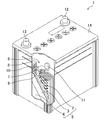
- FIG. 2 is an overview diagram schematically showing the configuration of the lead-acid battery 1 in the first embodiment of the present invention.
- an electrode plate group 5 in which a plurality of positive electrode plates 2 and negative electrode plates 3 are laminated via a separator 4 is accommodated in a cell chamber 6 together with an electrolytic solution.
- the positive electrode plate 2 includes a positive electrode lattice and a positive electrode active material filled in the positive electrode lattice
- the negative electrode plate 3 includes a negative electrode lattice and a negative electrode active material filled in the negative electrode lattice.
- the positive electrode lattice and the negative electrode lattice in this embodiment are both made of lead or a lead alloy containing no antimony (Sb), for example, a Pb—Ca alloy, a Pb—Sn alloy, or a Pb—Sn—Ca alloy.
- the plurality of positive electrode plates 2 are connected in parallel with each other by the positive electrode straps 7 between the positive electrode lattice ears 9, and the plurality of negative electrode plates 3 are connected in parallel with each other through the negative electrode lattice ears 10 between the negative electrode straps 8.
- the plurality of electrode plate groups 5 accommodated in each cell chamber 6 are connected in series by a connection body 11.
- Polar columns (not shown) are welded to the positive strap 7 and the negative strap 8 in the cell chambers 6 at both ends, respectively, and the respective polar columns are connected to the positive terminal 12 and the negative terminal 13 disposed on the lid 14. Each is welded.
- a surface layer (not shown) made of a lead alloy containing antimony is formed on the surface of the negative electrode lattice.
- the lead alloy containing antimony has an effect of lowering the hydrogen overvoltage, whereby the charge acceptability of the lead storage battery 1 can be improved.
- the surface layer is preferably made of a Pb—Sb alloy having an antimony content of 1.0 to 5.0 mass%.
- the mass ratio M N / M P of both 0.70 and 1. It is set in the range of 10, preferably in the range of 0.80 to 1.00.
- the mass ratio M N / M P of the negative electrode active material for the positive electrode active material is in this range, while maintaining the life characteristics, improved charge acceptance of the lead storage battery 1, the idling stop to be used in the "Choi ride" mode Even when applied to a vehicle, the operation of the fail-safe mechanism can be suppressed.
- the electrolytic solution contains sodium ions in the range of 0.01 to 0.45 mol / L, more preferably in the range of 0.03 to 0.28 mol / L.
- the sodium ions in the electrolyte have the effect of improving the overdischarge recovery, which further improves the charge acceptance of the lead storage battery 1 and is applied to an idling stop vehicle used in the “choi ride” mode.
- the operation of the fail-safe mechanism can be more effectively suppressed.
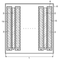
- W / L when the inner distance in the stacking direction of the electrode plate group 5 in the cell chamber 6 is L and the total thickness of the plurality of positive plates 2 and negative plates 3 is W, W / L is 0. It is preferably in the range of 50 to 0.80.
- the value of W / L is an index of the size of the gap between the positive electrode plate 2 and the negative electrode plate 3, in other words, the amount of wraparound of the electrolyte, and the W / L value is in the range of 0.50 to 0.80. If it exists, even if it applies to the idling stop vehicle used in "choi riding" mode, the charge acceptance property of lead acid battery 1 can improve further, and operation of a fail safe mechanism can be controlled more effectively.
- the negative electrode plate 3 is disposed on both sides of the electrode plate group 5, and the negative electrode plate 3 is accommodated in a bag-like separator 4. It is preferable that a plurality of ribs forming a certain gap be provided between the plate 3 and the separator 4. As a result, the electrolyte solution can also flow into the negative electrode plates 3 arranged on both sides of the electrode plate group 5, so that the charge acceptance of the lead storage battery 1 is further improved, and the idling stop used in the “choi riding” mode. Even when applied to a vehicle, the operation of the fail-safe mechanism can be more effectively suppressed.
- the separator 4 which accommodates the negative electrode plate 3 arrange
- the separator 4 may be provided with a plurality of ribs.
- the battery case of the lead storage battery 1 may also serve as the cell chamber 6.
- the lead acid battery 1 produced in the present example is a liquid lead acid battery having a D23L type size defined in JIS D5301.
- Each cell chamber 6 accommodates seven positive electrode plates 2 and eight negative electrode plates 3, and the negative electrode plate 3 is accommodated in a bag-like polyethylene separator 4.
- the positive electrode plate 2 was produced by kneading lead oxide powder with sulfuric acid and purified water to prepare a paste, and filling this into an expanded lattice made of a calcium-based lead alloy composition.
- the negative electrode plate 3 is prepared by adding an organic additive to lead oxide powder, kneading with sulfuric acid and purified water to prepare a paste, and filling this into an expanded lattice composed of a calcium-based lead alloy composition. Produced.
- the negative electrode plate 3 is accommodated in a polyethylene bag-like separator 4 and is alternately stacked with the positive electrode plates 2 to form seven positive electrode plates 2 and eight negative electrode plates.
- An electrode plate group 5 in which 3 and 3 were laminated via a separator 4 was produced.
- Each of the electrode plate groups 5 was accommodated in a cell chamber 6 partitioned into six, and a lead storage battery 1 in which six cells were directly connected was produced.
- SOC state of charge
- Example 1-1 On the surface of the negative electrode grid, to form a surface layer composed of a lead alloy containing antimony, when the mass of the positive electrode active material per cell chamber and M P, the mass of the negative active material and M N, by mass ratio M the N / M P to produce a battery A1 ⁇ A7 was changed in the range of 0.65 to 1.15, life characteristics of each cell, and the properties of the "Choi ride" mode was evaluated.
- the negative electrode lattice is composed of an expanded lattice of Pb-1.2Sn-0.1Ca, and the surface layer is composed of Pb-3 mass% Sb foil.
- the positive electrode lattice is an expanded lattice of Pb-1.6Sn-0.1Ca, and no surface layer is provided.
- Table 1 is a table showing the evaluation results of each characteristic.
- a battery A8 was prepared in which no surface layer was provided on the surface of the negative electrode lattice. Further, since it was difficult to produce an expanded lattice with a lead alloy containing Sb as the negative electrode lattice, it was excluded from the study.
- a lead-acid battery that satisfies these values can suppress the operation of the fail-safe mechanism while maintaining sufficient life characteristics even when the idling stop vehicle is used in the “choy ride” mode.
- the battery A3 ⁇ A5 in the range of mass ratio M N / M P is 0.80 to 1.00 is a lifetime characteristics 39,600 times or more, with SOC indicating "Choi ride” mode characteristic 74% or more Both have excellent performance when using an idling stop vehicle in the “Choide” mode.
- the life characteristic is 28,800 times, but the SOC indicating the “choi riding” mode characteristic is as low as 54%. This is presumably because the amount of the negative electrode active material is insufficient with respect to the amount of the positive electrode active material, so that the charge acceptance is reduced.
- the battery A7 mass ratio M N / M P 1.15 although SOC indicating "Choi ride” mode characteristic becomes 72%, the life characteristics are as low as 18,000 times. This is because the amount of the positive electrode active material is insufficient with respect to the amount of the negative electrode active material, and the softening of the positive electrode active material proceeds. It is considered that the deterioration of the positive electrode plate was advanced.
- the life characteristic is 28,800 times, but the SOC showing the “choy ride” mode characteristic is very low as 45%. This is presumably because the lead alloy foil containing Sb was not provided on the surface of the negative electrode lattice, so that the hydrogen overvoltage was not lowered and the charge acceptance was low.
- a storage battery can be realized.
- Example 1-2 Next, in order to further improve the charge acceptance, the content of Na ions in the electrolytic solution was changed to a range of 0.005 to 0.56 mol / L with respect to the battery A4 produced in Example 1-1. Batteries A9 to A15 were prepared, and the life characteristics of each battery and the characteristics of the “choy ride” mode were evaluated.
- the battery A12 is the same as the battery A4 manufactured in Example 1-1.
- the content of Na ions in the electrolytic solution was adjusted by changing the amount of sodium sulfate added to the electrolytic solution.
- This evaluation is based on the assumption that when a lead acid battery that has recovered after being in an overdischarged state is used again in “choi riding” mode and is repeatedly charged and discharged, the charge recovery is poor. This is a test assuming that the fail-safe mechanism is activated because the SOC is further reduced by the discharge while the SOC is low.
- the batteries A10 to A14 in which the content of Na ions in the electrolyte solution is in the range of 0.01 to 0.45 mol / L have a lifetime characteristic of 32,400 times or more and the “choy ride” mode. It can be seen that the SOC showing the characteristics is 70% or more, and the duration of the overdischarge recovery is 2.5 minutes or more. A lead-acid battery that satisfies these values can suppress the operation of the fail-safe mechanism while maintaining sufficient life characteristics even when the idling stop vehicle is used in the “choy ride” mode.
- the SOC that exhibits the “choy ride” mode characteristic with a life characteristic of 39,600 times or more is obtained. It is 74% or more and has a duration of 2.9 minutes or more showing the overdischarge recoverability, both of which are excellent and have a suitable performance when using an idling stop vehicle in the “choi ride” mode.
- the duration of the overdischarge recoverability is as short as 1.5 minutes. This is presumably because the conductivity at the time of overdischarge was reduced due to the small amount of Na ions.
- the SOC showing the “choy ride” mode characteristic is as low as 66%. This is thought to be because the charge acceptability was lowered due to the large amount of Na ions.
- Example 1-3 Next, in order to further improve the charge acceptance, the inner distance in the stacking direction of the electrode plate group in the cell chamber is set to L, a plurality of positive electrode plates and negative electrode plates with respect to the battery A4 manufactured in Example 1-1. Battery A16 to A22 with W / L in the range of 0.45 to 0.85 were prepared, and the life characteristics of each battery and the “choy ride” mode characteristics were evaluated. did.
- the battery A19 is the same as the battery A4 manufactured in Example 1-1.
- FIG. 3 shows a cross-sectional view of the cell chamber 6, where L is the inner distance in the stacking direction of the electrode plate group accommodated in the cell chamber 6, the thickness W 1 of the positive electrode plate 2, and the thickness of the negative electrode plate 3. As W2, the total thickness (W1 ⁇ 7 + W2 ⁇ 8) of the positive electrode plate 2 and the negative electrode plate 3 is W.
- Table 3 is a table showing the evaluation results of each characteristic.
- the life characteristics are 39,600 times or more, and the SOC showing the “choi riding” mode characteristics is 71% or more. It turns out that it is.
- a lead-acid battery that satisfies these values can suppress the operation of the fail-safe mechanism while maintaining sufficient life characteristics even when the idling stop vehicle is used in the “choy ride” mode.
- the batteries A18 to A20 having a W / L in the range of 0.60 to 0.70 have a lifetime characteristic of 39,600 times or more, a “choy ride” mode characteristic, and an SOC of 74% or more, both being excellent.
- the idling stop vehicle is used in the “choi riding” mode, it has a suitable performance.
- the life characteristic is 28,800 times, but the SOC indicating the “choy ride” mode characteristic is as low as 64%. This is thought to be due to a decrease in charge acceptance due to a lack of active material.
- the life characteristic is 39,600 times, but the SOC indicating the “choy ride” mode characteristic is as low as 66%. This is presumably because the electrolyte was not sufficiently rotated and the charge acceptance was reduced.
- Example 1-4 the battery A3 produced in Example 1-1 was placed inside the bag-shaped separator 4 containing the negative electrode plate 3, as shown in FIG.
- a battery A24 in which ribs 15 are provided on the positive electrode plate 2 side a battery A25 in which the positive electrode plate 2 is accommodated in the bag-like separator 4 and a rib 15 is provided on the negative electrode plate 3 side, and a bag-like separator.
- a battery A26 in which a plate-like separator was used instead of 4 and a rib 15 was provided on the negative electrode plate 3 side was produced.
- the height of the rib 15 was 0.2 mm, and was integrally formed with the separator 4.
- Table 4 is a table showing the evaluation results of each characteristic.
- the battery A23 provided with a rib on the negative electrode plate side inside the separator has a life characteristic of 39,600 times and an SOC showing a “choy ride” mode characteristic of 75%. .
- a lead-acid battery that satisfies these values can suppress the operation of the fail-safe mechanism while maintaining sufficient life characteristics even when the idling stop vehicle is used in the “choy ride” mode.
- the battery A24 provided with ribs on the positive electrode plate side, the positive electrode plate accommodated in a bag-like separator, the battery A25 provided with ribs on the negative electrode plate side, and a plate-like separator were used on the negative electrode plate side.
- the SOC showing the “choi riding” mode characteristics was as low as 67% or less. This is because when the negative electrode plates arranged on both sides of the electrode plate group are pressed against the inner wall of the cell chamber, no gap is formed between the negative electrode plate and the cell chamber, and the electrolyte does not circulate sufficiently. This is thought to be due to a decline in sex.
- the lead-acid battery can be charged by accommodating the negative electrode plate in a bag-shaped separator and providing a plurality of ribs that form a certain gap between the negative electrode plate and the separator inside the separator. Even if it is applied to an idling stop vehicle used in the “choi riding” mode, the operation of the fail-safe mechanism can be more effectively suppressed.
- FIG. 2 is an overview diagram schematically showing the configuration of the lead-acid battery 1 in the second embodiment of the present invention.
- a plurality of electrode plate groups 5 in which a plurality of positive electrode plates 2 and a negative electrode plate 3 are laminated via separators 4 are accommodated in a plurality of cell chambers 6 together with an electrolyte. ing.
- the positive electrode plate 2 includes a positive electrode lattice and a positive electrode active material filled in the positive electrode lattice
- the negative electrode plate 3 includes a negative electrode lattice and a negative electrode active material filled in the negative electrode lattice.
- the positive electrode lattice and the negative electrode lattice in this embodiment are both made of lead or a lead alloy containing no antimony (Sb), for example, a Pb—Ca alloy, a Pb—Sn alloy, or a Pb—Sn—Ca alloy.
- “Do not contain antimony” means that antimony is not added as an alloy component. If the raw material contains a small amount of antimony as an impurity, it does not contain antimony.
- the present invention does not contain antimony.
- the surface layer (not shown) containing antimony is formed in those surfaces.
- the surface layer is preferably made of a Pb—Sb alloy having an antimony content of 1.0 to 5.0 mass%.
- the plurality of positive electrode plates 2 are connected in parallel with each other by the positive electrode straps 7 between the positive electrode lattice ears 9, and the plurality of negative electrode plates 3 are connected in parallel with each other through the negative electrode lattice ears 10 between the negative electrode straps 8.
- the plurality of electrode plate groups 5 accommodated in each cell chamber 6 are connected in series by a connection body 11.
- Polar columns (not shown) are welded to the positive strap 7 and the negative strap 8 in the cell chambers 6 at both ends, respectively, and the respective polar columns are connected to the positive terminal 12 and the negative terminal 13 disposed on the lid 14. Each is welded.
- the positive electrode surface layer and the negative electrode surface layer containing antimony provided on the surfaces of the positive electrode lattice and the negative electrode lattice are derived from a Pb—Sb alloy foil bonded to the surface of a lead alloy plate as a material of the lattice. is there. Since the lattice structure is the same as that of the expanded metal, as shown in FIG. 4, when the cross section of the strand 31 of the lattice is observed by EPMA, a portion 32 containing Sb on one side of the quadrilateral cross sectional shape is observed. Is done.
- the area PS of the positive electrode surface layer is larger than the area NS of the negative electrode surface layer. That is, the value PS obtained by adding the areas of the positive electrode surface layers in each strand and bond in one whole positive electrode lattice is larger than the area value NS similarly added in the whole one negative electrode lattice.
- PS and NS are approximately equal to the area of the Pb—Sb alloy foil bonded to the surface of the lead alloy plate as the material of the lattice.
- the merit of providing an antimony-containing layer on the surface of the negative electrode lattice is that the negative electrode can be prevented from being burnt in the idling stop mode, and the negative electrode plate can be efficiently charged and recovered.
- the disadvantage is that it accelerates the electrolysis of water. Therefore, it is not preferable to unnecessarily increase the area of the negative electrode surface layer.
- the inventors of the present application further examined that, when charging and discharging are repeated, Pb as a negative electrode active material and lead sulfate as a discharge product accumulate on the surface layer of the negative electrode grid, and the surface layer is covered to charge the negative electrode plate. It has been found that the recovery function is degraded. This is a major disadvantage for the idling stop vehicle used in the “choi ride” mode.
- various types of “choy riding” modes can be used in idling stop vehicles. It has been found that the above demerits can be eliminated without deteriorating the characteristics. Furthermore, it has been found that the “choy ride” mode characteristics are further improved when NS / PS is 0.3 or more.
- the negative electrode surface layer has a higher antimony content than the positive electrode surface layer. It is preferable to do. Thereby, the charge acceptability of the lead storage battery 1 can be improved over a long period of time, and the operation of the fail-safe mechanism can be further suppressed even when applied to an idling stop vehicle used in the “choy ride” mode.
- the positive electrode grid is preferably manufactured by a reciprocating method in which no twist is generated.
- the electrolytic solution contains aluminum ions.
- the charge acceptance performance of the lead storage battery can be improved, and even when applied to an idling stop vehicle used in the “choi riding” mode.
- the operation of the fail-safe mechanism can be further suppressed.
- the mass ratio M N / M P of both 0.70 and 1. It is set in the range of 10, preferably in the range of 0.80 to 1.0.
- the mass ratio M N / M P of the negative electrode active material for the positive electrode active material is in this range, while maintaining the life characteristics, improved charge acceptance of the lead storage battery 1, the idling stop to be used in the "Choi ride" mode Even when applied to a vehicle, the operation of the fail-safe mechanism can be suppressed.
- the electrolytic solution contains 0.01 to 0.45 mol / L, more preferably 0.03 to 0.28 mol / L of sodium ions.
- the sodium ions in the electrolyte have the effect of improving the overdischarge recovery, which further improves the charge acceptance of the lead storage battery 1 and is applied to an idling stop vehicle used in the “choi ride” mode.
- the operation of the fail-safe mechanism can be more effectively suppressed.
- W / L when the inner distance in the stacking direction of the electrode plate group 5 in the cell chamber 6 is L and the total thickness of the plurality of positive plates 2 and negative plates 3 is W, W / L is 0. It is preferably in the range of 50 to 0.80.
- the value of W / L is an index of the size of the gap between the positive electrode plate 2 and the negative electrode plate 3, in other words, the amount of wraparound of the electrolyte, and the W / L value is in the range of 0.50 to 0.80. If it exists, even if it applies to the idling stop vehicle used in "choi riding" mode, the charge acceptance property of lead acid battery 1 can improve further, and operation of a fail safe mechanism can be controlled more effectively.
- the negative electrode plate 3 is disposed on both sides of the electrode plate group 5, and the negative electrode plate 3 is accommodated in a bag-like separator 4. It is preferable that a plurality of ribs forming a certain gap be provided between the plate 3 and the separator 4. As a result, the electrolyte solution can also flow into the negative electrode plates 3 arranged on both sides of the electrode plate group 5, so that the charge acceptance of the lead storage battery 1 is further improved, and the idling stop used in the “choi riding” mode. Even when applied to a vehicle, the operation of the fail-safe mechanism can be more effectively suppressed.
- the separator 4 which accommodates the negative electrode plate 3 arrange
- the separator 4 may be provided with a plurality of ribs.
- the battery case of the lead storage battery 1 may also serve as the cell chamber 6.
- the lead acid battery 1 produced in the present example is a liquid lead acid battery having a D23L type size defined in JIS D5301.
- Each cell chamber 6 accommodates seven positive electrode plates 2 and eight negative electrode plates 3, and the negative electrode plate 3 is accommodated in a bag-like polyethylene separator 4.
- Table 5 shows the configurations and battery characteristics of the batteries B1 to B9 according to the example and the comparative batteries A and B according to the comparative example.
- the positive electrode plate 2 was produced by kneading lead oxide powder with sulfuric acid and purified water to prepare a paste, and filling this into an expanded lattice made of a calcium-based lead alloy composition.
- the negative electrode plate 3 is prepared by adding an organic additive to lead oxide powder, kneading with sulfuric acid and purified water to prepare a paste, and filling this into an expanded lattice composed of a calcium-based lead alloy composition. Produced.
- the negative electrode lattice is composed of an expanded lattice prepared by a rotary method of Pb-1.2Sn-0.1Ca, and the surface layer is composed of Pb-3 mass% Sb foil (only Pb-2 mass% Sb foil in Example 8).
- the positive electrode lattice is an expanded lattice produced by a reciprocating method of Pb-1.6Sn-0.1Ca, and the surface layer is made of Pb-2 mass% Sb foil (only battery B8 is Pb-3 mass% Sb foil). ).
- the negative electrode plate 3 is accommodated in a polyethylene bag-like separator 4 and is alternately stacked with the positive electrode plates 2 to form seven positive electrode plates 2 and eight negative electrode plates.
- An electrode plate group 5 in which 3 and 3 were laminated via a separator 4 was produced.
- Each of the electrode plate groups 5 was accommodated in a cell chamber 6 divided into six, and a lead storage battery 1 in which six cells were connected in series was produced.
- SOC state of charge
- the SOC showing the “choi riding” mode characteristic is 70% or more.
- a lead-acid battery that satisfies these values can suppress the operation of the fail-safe mechanism while maintaining sufficient life characteristics even when the idling stop vehicle is used in the “choy ride” mode.
- the batteries B3 to B5 having an area ratio of NS / PS in the range of 0.4 to 0.6 have an excellent SOC of “choy ride” mode characteristics of 75% or more, and idling stop in the “choy ride” mode. When using a car, it has suitable performance.
- the SOC indicating the “choi riding” mode characteristic is as low as 66%. This is probably because the amount of Sb on the negative electrode side is insufficient with respect to the positive electrode side, so that charge acceptability is lowered, but there is no problem in practical use.
- the SOC showing the “choi riding” mode characteristic is as low as 66%. This is considered to be because the amount of Sb on the negative electrode side is larger than that on the positive electrode side, so that the electrolysis of water was accelerated and the charging efficiency of the negative electrode plate was lowered.
- the SOC showing “choy ride” mode characteristics is very low at 45%, and the fail-safe mechanism is activated.
- the amount of Sb on the negative electrode side is larger than that on the positive electrode side, so that the electrolysis of water was accelerated and the charging efficiency of the negative electrode plate was reduced.
- Comparative Battery B which has a positive electrode surface layer but no negative electrode lattice layer, the SOC showing “choy ride” mode characteristics is very low at 40%, and the fail-safe mechanism is activated. End up. This is presumably because the lead alloy foil containing Sb was not provided on the surface of the negative electrode lattice, so that the hydrogen overvoltage was not lowered and the charge acceptance was low.
- a positive electrode surface layer and a negative electrode surface layer made of a lead alloy containing antimony are formed on the surfaces of the positive electrode lattice and the negative electrode lattice that do not contain antimony, and the area of the positive electrode surface layer is the area of the negative electrode surface layer.
- a battery B8 was produced in which the negative electrode surface layer was a Pb-2 mass% Sb foil and the positive electrode surface layer was a Pb-3 mass% Sb foil.
- Battery B8 has an SOC showing “choy ride” mode characteristics of 70%, which is inferior to battery B4. However, when the idling stop vehicle is used in “choy ride” mode, it has suitable performance.
- a battery B9 was prepared by adding 0.1% by mass of aluminum ions in the electrolyte to the battery B4, and the “choy ride” mode characteristics were evaluated. .
- the SOC showing the “choy ride” mode characteristic is very high at 80%, and when the idling stop vehicle is used in the “choy ride” mode, it has a very suitable performance.
- FIG. 2 is an overview diagram schematically showing the configuration of the lead-acid battery 1 in the third embodiment of the present invention.
- an electrode plate group 5 in which a plurality of positive electrode plates 2 and negative electrode plates 3 are laminated via a separator 4 is accommodated in a cell chamber 6 together with an electrolytic solution.
- the positive electrode plate 2 includes a positive electrode lattice (not shown) and a positive electrode active material (not shown) filled in the positive electrode lattice, and the negative electrode plate 3 is filled in the negative electrode lattice 3a and the negative electrode lattice 3a.
- the positive electrode lattice and the negative electrode lattice 3a in the present embodiment are both made of lead or a lead alloy not containing antimony (Sb), for example, a Pb—Ca alloy, a Pb—Sn alloy, or a Pb—Ca—Sn alloy. .
- “Do not contain antimony” means that antimony is not added as an alloy component. If the raw material contains a small amount of antimony as an impurity, it does not contain antimony. That is, when antimony is an unavoidable impurity, the present invention does not contain antimony.
- the plurality of positive electrode plates 2 are connected in parallel with each other by the positive electrode straps 7 between the positive electrode lattice ears 9, and the plurality of negative electrode plates 3 are connected in parallel with each other through the negative electrode lattice ears 10 between the negative electrode straps 8.
- the plurality of electrode plate groups 5 accommodated in each cell chamber 6 are connected in series by a connection body 11.
- Polar columns are welded to the positive strap 7 and the negative strap 8 in the cell chambers 6 at both ends, respectively, and each polar column is welded to the positive terminal 12 and the negative terminal 13 disposed on the lid 14, respectively. Yes.
- the density of the positive electrode active material in the positive electrode plate 2 is 3.6 g / ml or more and 4.8 g / ml or less.
- the total pore volume in the positive electrode active material is 0.06 ml / g or more and 0.18 ml / g or less.
- the negative electrode plate 3 is disposed on both sides of the electrode plate group 5, and the negative electrode plate 3 is accommodated in a bag-like separator 4.
- the density of the positive electrode active material is less than 3.6 g / ml, or if the total pore volume in the positive electrode active material is greater than 0.18 ml / g, the battery capacity of the lead acid battery as a whole will be reduced and “choy” for idling stop applications. Battery life in "ride” mode is shortened. Conversely, if the density of the positive electrode active material is larger than 4.8 g / ml, or if the total pore volume in the positive electrode active material is smaller than 0.06 ml / g, the SOC decreases in the “choy ride” mode for idling stop applications. Will occur early, and the fail-safe mechanism will operate early and frequently.
- the SOC will be lowered early in the “choi riding” mode. Since the present inventors have found for the first time that the decrease in the SOC occurs early and the fail-safe mechanism operates early and frequently, this will be described below.
- the positive electrode active material density is set to 3.5 to 4.5 g / cc in order to solve the short life caused by the increase in the discharge frequency caused by the use conditions where the frequency of temporary stop with idling stop is high. It is disclosed that the electrolyte has a specific gravity of 1.240 to 1.260 (20 ° C.) and the amount of carbon that is an additive of the negative electrode plate is 0.5 to 2.0% per mass of the negative electrode active material.
- Patent Document 4 it is described that the short life by repeating the deep discharge many times under the above conditions is improved, and in the embodiment, charging and deep discharge are performed when all three of the above conditions are provided. Although it is disclosed that the service life is improved in repeated tests, no consideration has been given to the low use frequency and “choy riding” mode of the idling stop vehicle. Further, there is no disclosure about the positions of the positive electrode plate / negative electrode plate and the shape / position of the separator.
- the present inventors have found that the problem can be solved by accommodating the density or total pore volume of the positive electrode active material and the negative electrode plate in a bag-like separator as described above.
- the separator 4 exists in the boundary portion with the cell chamber in the negative electrode plate 3 arranged on both sides of the electrode plate group 5, so that the electrolytic solution passes through the separator 4.
- the negative electrode plate 3 can also go around the cell chamber and the contact surface side. Therefore, the charge acceptability of the lead storage battery 1 is further improved, and the operation of the fail-safe mechanism can be more effectively suppressed even when applied to an idling stop vehicle used in the “choy ride” mode.
- a surface layer (not shown) made of a lead alloy containing antimony is formed on the surface of the negative electrode lattice 3a.
- the lead alloy containing antimony has an effect of lowering the hydrogen overvoltage, whereby the charge acceptability of the lead storage battery 1 can be improved.
- the surface layer is preferably made of a Pb—Sb alloy having an antimony content of 1.0 to 5.0 mass%.
- the electrolytic solution contains 0.01 to 0.45 mol / L, more preferably 0.03 to 0.28 mol / L of sodium ions.
- the sodium ions in the electrolyte have the effect of improving the overdischarge recovery, which further improves the charge acceptance of the lead storage battery 1 and is applied to an idling stop vehicle used in the “choi ride” mode.
- the operation of the fail-safe mechanism can be more effectively suppressed.
- W / L when the inner distance in the stacking direction of the electrode plate group 5 in the cell chamber 6 is L and the total thickness of the plurality of positive plates 2 and negative plates 3 is W, W / L is 0. It is preferably in the range of 50 to 0.80.
- the value of W / L is an index of the size of the gap between the positive electrode plate 2 and the negative electrode plate 3, in other words, the amount of wraparound of the electrolyte, and the W / L value is in the range of 0.50 to 0.80. If it exists, even if it applies to the idling stop vehicle used in "choi riding" mode, the charge acceptance property of lead acid battery 1 can improve further, and operation of a fail safe mechanism can be controlled more effectively.
- the electrolyte solution can also flow into the negative electrode plates 3 arranged on both sides of the electrode plate group 5, so that the charge acceptance of the lead storage battery 1 is further improved, and the idling stop used in the “choi riding” mode. Even when applied to a vehicle, the operation of the fail-safe mechanism can be more effectively suppressed.
- the separator 4 which accommodates the negative electrode plate 3 arrange
- the separator 4 may be provided with a plurality of ribs.
- the battery case of the lead storage battery 1 may also serve as the cell chamber 6.
- the mass ratio M N / M P of both 0.70 and 1. It is preferably set in the range of 10, preferably in the range of 0.80 to 1.0.
- the mass ratio M N / M P of the negative electrode active material for the positive electrode active material is in this range, while maintaining the life characteristics, improved charge acceptance of the lead storage battery 1, the idling stop to be used in the "Choi ride" mode This is because even when applied to a car, the operation of the fail-safe mechanism can be further suppressed.
- the lead acid battery 1 produced in the present example is a liquid lead acid battery having a D23L type size defined in JIS D5301.
- Each cell chamber 6 accommodates seven positive electrode plates 2 and eight negative electrode plates 3, and a separator 4 exists between the positive electrode plate 2 and the negative electrode plate 3.
- Table 6 shows the configurations and battery characteristics of the batteries C1 to C18 according to the example and the comparative batteries A to D according to the comparative example.
- the positive electrode plate 2 was produced by kneading lead oxide powder with sulfuric acid and purified water to prepare a paste, and filling this into an expanded lattice made of a calcium-based lead alloy composition.
- the negative electrode plate 3 is prepared by adding an organic additive to lead oxide powder, kneading with sulfuric acid and purified water to prepare a paste, and filling this into an expanded lattice composed of a calcium-based lead alloy composition. Produced.
- the negative electrode lattice is composed of an expanded lattice of Pb-1.2Sn-0.1Ca, and the surface layer is composed of Pb-3 mass% Sb foil. Further, the positive electrode lattice is an expanded lattice of Pb-1.6Sn-0.1Ca, and no surface layer is provided.
- the positive electrode plates 2 and the negative electrode plates 3 are aged and dried, the positive electrode plates 2 and the negative electrode plates 3 are alternately stacked via the separators 4, and the seven positive electrode plates 2 and the eight negative electrode plates 3 are separated.
- the electrode plate group 5 laminated through 4 was produced.
- the electrode plate group 5 was housed in a cell chamber 6 partitioned into six, and lead storage batteries according to Examples and Comparative Examples in which six cells were connected in series were produced.
- the volume a of a sample (active material of the positive electrode plate) in which mercury is injected under the condition that a hole of 5 ⁇ m diameter or more is filled is obtained, and the mass b of the sample is divided by this density b / a (g / ml) Asked.
- SOC state of charge
- Charge recovery after overdischarge is evaluated when the lead acid battery is overdischarged and the recovered lead acid battery is used again in the “choi ride” mode and is repeatedly charged and discharged. This is a test that assumes that if the performance is poor, the SOC will decrease due to the discharge due to a decrease in charge acceptance due to a decrease in the reaction surface area, and the situation where the fail-safe mechanism operates will become significant.
- the batteries C2 to C4 having a positive electrode active material density of 3.9 to 4.5 g / ml or a total pore volume in the positive electrode active material of 0.09 to 0.15 ml / g have a life characteristic of 39, More than 000 times, the “choy ride” mode characteristics are also excellent, both with an SOC of 75% or more, and suitable performance when using an idling stop vehicle in the “choy ride” mode.
- the “choy ride” mode characteristic has a SOC of 75%, but the life characteristic is as low as 18,000 times. This is presumably because the overall battery capacity was reduced because the positive electrode active material was softened by charge / discharge and dropped from the electrode plate.
- the comparative battery B having a positive electrode active material density of more than 4.8 g / ml of 5 g / ml or a total pore volume in the positive electrode active material of less than 0.06 ml / g, the comparative battery B has a life characteristic. Is excellent at 57,600 times, but the “choy ride” mode characteristic has a low SOC of 45%. This is considered to be because the positive electrode active material is too densely packed, so that the electrolyte sufficiently enters the positive electrode and cannot be involved in charge / discharge.
- Separatator shape A comparative example in which the shape of the separator is not a bag shape but a plate shape (that is, the negative electrode plate is only sandwiched between the positive electrode and the separator is not wrapped) based on the battery C3 of the example.
- the comparative battery C according to the above and the comparative battery D housed in a positive electrode plate bag-like separator instead of the negative electrode plate were prepared and evaluated (Table 6).
- the comparative battery C has an excellent life characteristic of 39,600 times, but the “choy ride” mode characteristic has a low SOC of 50%.
- the comparative battery D like the comparative battery C, has a “choy ride” mode characteristic, and the SOC is as low as 51%.
- the “choi riding” mode characteristic is inferior because the negative electrode plate is in close contact with the cell chamber wall unlike the battery C3, and the electrolyte cannot enter the boundary surface, and the negative electrode active This is probably because a part of the substance is not used and the charge acceptability is lowered.
- the content of Na ions contained in the electrolytic solution was adjusted by changing the amount of sodium sulfate added to the electrolytic solution.
- the life characteristics are 43,000 times or more, and the “choy ride” mode
- the SOC is 70% or more
- the duration of the overdischarge recovery is 3 minutes or more.
- the life characteristics are 46,000 times or more, and the “choy ride” mode characteristics are also
- the SOC is 75% or more and the duration of overdischarge recovery is 3 minutes or more, both of which are excellent, and suitable performance when using an idling stop vehicle in the “choi ride” mode.
- the duration of the overdischarge recoverability is as short as 1.5 minutes. This is considered to be because the conductivity at the time of overdischarge was lowered because of a small amount of Na ions.
- the SOC showing the “choy ride” mode characteristic is as low as 65%. This is thought to be due to the fact that the charge acceptability has decreased due to the large amount of Na ions.
- FIG. 3 shows a cross-sectional view of the cell chamber 6, where L is the inner distance in the stacking direction of the electrode plate group accommodated in the cell chamber 6, the thickness W 1 of the positive electrode plate 2, and the thickness of the negative electrode plate 3. As W2, the total thickness (W1 ⁇ 7 + W2 ⁇ 8) of the positive electrode plate 2 and the negative electrode plate 3 is W.
- the life characteristics are 39,000 times or more, and the SOC indicating the “choi riding” mode characteristics is 70. It turns out that it is more than%.
- a lead-acid battery that satisfies these values can suppress the operation of the fail-safe mechanism while maintaining sufficient life characteristics even when the idling stop vehicle is used in the “choy ride” mode.
- the batteries C3, C14, and C15 having a W / L in the range of 0.60 to 0.70 have a life characteristic of 43,000 times or more, a “choy ride” mode characteristic, and an SOC of 75% or more. Excellent, suitable performance when using an idling stop vehicle in “choy ride” mode.
- the life characteristic is 39,600 times, but the “choy ride” mode characteristic has a low SOC of 69%. This is thought to be due to the lack of active material, which reduced charge acceptance.
- the life characteristic is 57,600 times, but the “choy ride” mode characteristic has a low SOC of 69%. This is presumably because the electrolyte was not sufficiently rotated and the charge acceptance was reduced.
- a certain gap is formed between the negative electrode plate 3 and the separator 4 inside the bag-shaped separator 4 containing the negative electrode plate 3.
- a plurality of ribs 15 are provided.
- a battery C ⁇ b> 18 in which the rib 15 was not provided on the negative electrode plate 3 side but provided on the positive electrode plate 2 side was produced and evaluated.
- the height of the rib 15 was 0.2 mm and was formed integrally with the separator 4.
- the life characteristic is 46,000 times or more, and the “choy ride” mode characteristic is also SOC is 75% or more. I understand. A lead-acid battery that satisfies these values can suppress the operation of the fail-safe mechanism while maintaining sufficient life characteristics even when the idling stop vehicle is used in the “choy ride” mode.
- the battery C18 provided with ribs on the positive electrode plate side had a low SOC of 55% indicating “choy ride” mode characteristics. This is because when the negative electrode plates arranged on both sides of the electrode plate group are pressed against the inner wall of the cell chamber, no gap is formed between the negative electrode plate and the cell chamber, and the electrolyte does not circulate sufficiently. This is thought to be due to a decline in sex.
- the lead-acid battery can be charged by accommodating the negative electrode plate in a bag-shaped separator and providing a plurality of ribs that form a certain gap between the negative electrode plate and the separator inside the separator. Even if it is applied to an idling stop vehicle used in the “choi riding” mode, the operation of the fail-safe mechanism can be more effectively suppressed.
- tin sulfate may be added to the positive electrode. It is preferable to add tin sulfate to the positive electrode because the discharge capacity is improved.
- FIG. 2 is an overview diagram schematically showing the configuration of the lead storage battery 1 according to the fourth embodiment of the present invention.
- an electrode plate group 5 in which a plurality of positive electrode plates 2 and negative electrode plates 3 are laminated via a separator 4 is accommodated in a cell chamber 6 together with an electrolytic solution.
- the positive electrode plate 2 includes a positive electrode lattice and a positive electrode active material filled in the positive electrode lattice
- the negative electrode plate 3 includes a negative electrode lattice and a negative electrode active material filled in the negative electrode lattice.
- the positive electrode lattice and the negative electrode lattice in this embodiment are both made of lead or a lead alloy containing no antimony (Sb), for example, a Pb—Ca alloy, a Pb—Sn alloy, or a Pb—Sn—Ca alloy.
- the plurality of positive electrode plates 2 are connected to each other in parallel with each other by the positive electrode straps (electrode plate connection plates) 7 at the ears 9 of the positive electrode lattice. They are connected in parallel by (electrode plate connection plate) 8. Further, the plurality of electrode plate groups 5 accommodated in each cell chamber 6 are connected in series via a connection body 11. Polar columns (not shown) are welded to the positive strap 7 and the negative strap 8 in the cell chambers 6 at both ends, respectively, and the respective polar columns are connected to the positive terminal 12 and the negative terminal 13 disposed on the lid 14. Each is welded.
- a surface layer (not shown) made of a lead alloy containing antimony is formed on the surface of the negative electrode lattice.
- the lead alloy containing antimony has an effect of lowering the hydrogen overvoltage, whereby the charge acceptability of the lead storage battery 1 can be improved.
- the surface layer is preferably made of a Pb—Sb alloy having an antimony content of 1.0 to 5.0 mass%.
- the mass ratio Ms / M P is from .50 to .74 And more preferably within the range of 0.57 to 0.70.
- W / L when the inner distance in the stacking direction of the electrode plate group 5 in the cell chamber 6 is L and the total thickness of the plurality of positive plates 2 and negative plates 3 is W, W / L is 0. It is preferably in the range of 50 to 0.80.
- the value of W / L is an index of the size of the gap between the positive electrode plate 2 and the negative electrode plate 3, in other words, the amount of wraparound of the electrolyte, and the W / L value is in the range of 0.50 to 0.80. If it exists, even if it applies to the idling stop vehicle used in "choi riding" mode, the charge acceptance property of lead acid battery 1 can improve further, and operation of a fail safe mechanism can be controlled more effectively.
- the density of the positive electrode active material is preferably set in the range of 3.6 to 4.8 g / ml, more preferably in the range of 3.9 to 4.5 g / ml.
- the electrode plate connection plates (straps) 7 and 8 and the connection body 11 preferably do not contain antimony and are made of a lead alloy containing tin. Since the electrode plate connection plates (straps) 7 and 8 and the connection body 11 (hereinafter referred to as “connection parts”) do not contain antimony, corrosion of the ears 9 and 10 caused by the antimony eluting into the electrolyte is suppressed. The Thereby, the life characteristics of the lead storage battery 1 are further improved, and the operation of the fail-safe mechanism can be more effectively suppressed even when applied to an idling stop vehicle used in the “choy ride” mode.
- the lead acid battery 1 produced in the present example is a liquid lead acid battery having a D23L type size defined in JIS D5301.
- Each cell chamber 6 accommodates seven positive electrode plates 2 and eight negative electrode plates 3, and the negative electrode plate 3 is accommodated in a bag-like polyethylene separator 4.
- the positive electrode plate 2 was produced by kneading lead oxide powder with sulfuric acid and purified water to prepare a paste, and filling this into an expanded lattice made of a calcium-based lead alloy composition.
- the negative electrode plate 3 is prepared by adding an organic additive to lead oxide powder, kneading with sulfuric acid and purified water to prepare a paste, and filling this into an expanded lattice composed of a calcium-based lead alloy composition. Produced.
- the negative electrode plate 3 is accommodated in a polyethylene bag-like separator 4 and is alternately stacked with the positive electrode plates 2 to form seven positive electrode plates 2 and eight negative electrode plates.
- An electrode plate group 5 in which 3 and 3 were laminated via a separator 4 was produced.
- Each of the electrode plate groups 5 was accommodated in a cell chamber 6 partitioned into six, and a lead storage battery 1 in which six cells were directly connected was produced.
- SOC state of charge
- Example 4-1 When a surface layer made of a lead alloy containing antimony is formed on the surface of the negative electrode lattice, the mass ratio of the positive electrode active material per cell chamber is M P , and the mass of sulfuric acid contained in the electrolyte is Ms. to produce a battery D1 ⁇ D7 of varying ms / M P in the range from 0.45 to 0.98 life characteristics of the battery, and to evaluate the properties of the "Choi ride" mode.
- the negative electrode lattice is composed of an expanded lattice of Pb-1.2Sn-0.1Ca, and the surface layer is composed of Pb-3 mass% Sb foil.
- the positive electrode lattice is an expanded lattice of Pb-1.6Sn-0.1Ca, and no surface layer is provided.
- the mass of the positive electrode active material the range of 1.5 to 2.5 mol
- the mass of sulfuric acid in place of the range of 2.4 to 3.6 mol, make adjustments in mass ratio Ms / M P It was.
- Table 7 is a table showing the evaluation results of each characteristic.
- a battery D8 was prepared in which no surface layer was provided on the surface of the negative electrode lattice.
- the batteries D2 ⁇ 6 range of the mass ratio Ms / M P is 0.50 to 0.74, in lifetime characteristics than 36,000 times, the SOC indicating "Choi ride” mode characteristics It turns out that it is 71% or more.
- a lead-acid battery that satisfies these values can suppress the operation of the fail-safe mechanism while maintaining sufficient life characteristics even when the idling stop vehicle is used in the “choy ride” mode.
- batteries D3 ⁇ D5 ranging mass ratio Ms / M P is 0.57 to 0.70 is a lifetime characteristics 43,200 times or more, with SOC indicating "Choi ride” mode characteristic 74% or more, Both are excellent and have a suitable performance when using an idling stop vehicle in the “choi ride” mode.
- the life characteristic is 39,600 times, but the SOC indicating the “choy ride” mode characteristic is very low as 49%. This is presumably because the lead alloy foil containing Sb was not provided on the surface of the negative electrode lattice, so that the hydrogen overvoltage was not lowered and the charge acceptance was low.
- a suitable lead storage battery can be realized.
- the inner distance in the stacking direction of the electrode plate group in the cell chamber is set to L, and the total thickness of the plurality of positive electrode plates and negative electrode plates with respect to the battery D4 manufactured in Example 4-1.
- D is W
- batteries D9 to D15 with W / L changed in the range of 0.45 to 0.85 were fabricated, and the life characteristics of each battery and the characteristics of the “choi riding” mode were evaluated.
- the battery D12 is the same as the battery D4 manufactured in Example 4-1.
- FIG. 3 shows a cross-sectional view of the cell chamber 6, where L is the inner distance in the stacking direction of the electrode plate group accommodated in the cell chamber 6, the thickness W 1 of the positive electrode plate 2, and the thickness of the negative electrode plate 3. As W2, the total thickness (W1 ⁇ 7 + W2 ⁇ 8) of the positive electrode plate 2 and the negative electrode plate 3 is W.
- Table 8 is a table showing the evaluation results of each characteristic.
- the life characteristics are 36,000 times or more, and the SOC showing the “choi riding” mode characteristics is 71% or more. It turns out that it is.
- a lead-acid battery that satisfies these values can suppress the operation of the fail-safe mechanism while maintaining sufficient life characteristics even when the idling stop vehicle is used in the “choy ride” mode.
- the batteries D11 to D13 having a W / L in the range of 0.60 to 0.70 have a lifetime characteristic of 39,600 times or more, show a “choy ride” mode characteristic, and have an SOC of 74% or more. When the idling stop vehicle is used in the “choi riding” mode, it has a suitable performance.
- the life characteristic is 36,000 times, but the SOC indicating the “choy ride” mode characteristic is as low as 63%. This is presumably because the amount of the negative electrode active material is insufficient with respect to the amount of the positive electrode active material, so that the charge acceptance is reduced.
- the life characteristic is 36,000 times, but the SOC indicating the “choy ride” mode characteristic is as low as 61%. This is presumably because the electrolyte was not sufficiently rotated and the charge acceptance was reduced.
- the battery D19 is the same as the battery D4 manufactured in Example 4-1.
- the density of a positive electrode active material says the density after chemical conversion, and was measured with the following method.
- the total pore volume of the positive electrode with respect to the density of each positive electrode active material was also measured.
- Table 9 is a table showing the evaluation results of each characteristic.
- the density of the positive electrode active material is in the range of 3.6 to 4.8 g / ml (the total pore volume of the positive electrode is in the range of 0.06 to 0.18 ml / g). It can be seen that the SOC showing the “choi riding” mode characteristic is 71% or more when the life characteristic is 36,000 times or more. A lead-acid battery that satisfies these values can suppress the operation of the fail-safe mechanism while maintaining sufficient life characteristics even when the idling stop vehicle is used in the “choy ride” mode.
- the batteries D18-20 in which the density of the positive electrode active material is in the range of 3.9 to 4.5 g / ml (the total pore volume of the positive electrode is in the range of 0.09 to 0.15 ml / g) have a life characteristic of 39. , 600 times or more, the SOC showing the “choy ride” mode characteristic is 74% or more, both are excellent, and suitable performance when using an idling stop vehicle in the “choy ride” mode.
- the SOC showing the “choy ride” mode characteristic is 75%.
- the life characteristics are as low as 28,800 times. This is presumably because the positive electrode plates deteriorated because the binding properties of the positive electrode active materials were low.
- the battery D22 having a positive electrode active material density of 5.0 g / ml (the total pore volume of the positive electrode is 0.04 ml / g) has a life characteristic of 43,200 times.
- the SOC shown is as low as 55%. This is presumably because the positive electrode active material is too densely packed, so that the electrolyte does not sufficiently rotate around the positive electrode, and the charge acceptance is reduced.
- the density of the positive electrode active material is in the range of 3.6 to 4.8 g / ml (the total pore volume of the positive electrode is in the range of 0.06 to 0.18 ml / g), more preferably the positive electrode active material.
- the total pore volume of the positive electrode is in the range of 0.09 to 0.15 ml / g)
- charging is accepted while maintaining sufficient life characteristics. Even if it is applied to an idling stop vehicle used in the “choi riding” mode, the operation of the fail-safe mechanism can be more effectively suppressed.
- Example 4-4 Next, in order to further improve the life characteristics, the battery D4 manufactured in Example 4-1 was changed in the configuration of the connection parts (electrode plate connection plate (strap)) 7 and 8 and the connection body 11. D23 was produced, and the life characteristics of the battery D4 and the battery D23 and the characteristics of the “choy ride” mode were evaluated.
- the connecting part of the battery D23 is made of a lead alloy containing antimony (Pb-2.7Sb), and the connecting part of the battery D4 is a lead alloy containing no antimony and containing tin (Pb-2.5Sn). ).
- Table 10 is a table showing the evaluation results of each characteristic.
- the battery D4 in which the connecting part does not contain antimony and is made of a lead alloy containing tin has a longer life characteristic than the battery D23 in which the connecting part is made of a lead alloy containing antimony. You can see that This is probably because the connection parts of the battery D4 do not contain antimony, and thus the corrosion of the ears 9 and 10 caused by the antimony eluting into the electrolyte is suppressed.
- the life characteristics are further improved by using the lead alloy containing tin without containing antimony and the connecting parts including the electrode plate connecting plate and connecting body, and used in the “choi riding” mode. Even when applied to an idling stop vehicle, the operation of the fail-safe mechanism can be more effectively suppressed.
- the pole column which connects an electrode plate connection board and an external terminal is included, and the said pole column may also be comprised with the lead alloy which does not contain antimony but contains tin.
- FIG. 2 is an overview diagram schematically showing the configuration of the lead-acid battery 1 in the fifth embodiment of the present invention.
- an electrode plate group 5 in which a plurality of positive electrode plates 2 and negative electrode plates 3 are laminated via a separator 4 is accommodated in a cell chamber 6 together with an electrolytic solution.
- the positive electrode plate 2 includes a positive electrode lattice and a positive electrode active material filled in the positive electrode lattice
- the negative electrode plate 3 includes a negative electrode lattice and a negative electrode active material filled in the negative electrode lattice.
- the positive electrode lattice and the negative electrode lattice in this embodiment are both made of lead or a lead alloy containing no antimony (Sb), for example, a Pb—Ca alloy, a Pb—Sn alloy, or a Pb—Sn—Ca alloy.
- the plurality of positive electrode plates 2 are connected in parallel with each other by the positive electrode straps 7 between the positive electrode lattice ears 9, and the plurality of negative electrode plates 3 are connected in parallel with each other through the negative electrode lattice ears 10 between the negative electrode straps 8.
- the plurality of electrode plate groups 5 accommodated in each cell chamber 6 are connected in series by a connection body 11.
- Polar columns (not shown) are welded to the positive strap 7 and the negative strap 8 in the cell chambers 6 at both ends, respectively, and the respective polar columns are connected to the positive terminal 12 and the negative terminal 13 disposed on the lid 14. Each is welded.
- a surface layer (not shown) made of a lead alloy containing antimony is formed on the surface of the negative electrode lattice 3a.
- the lead alloy containing antimony has an effect of lowering the hydrogen overvoltage, whereby the charge acceptability of the lead storage battery 1 can be improved.
- the surface layer is preferably made of a Pb—Sb alloy having an antimony content of 1.0 to 5.0 mass%.
- the negative electrode plate 3 is disposed on both sides of the electrode plate group 5, and the negative electrode plate 3 is accommodated in a bag-like separator 4.
- the electrolyte solution can also flow into the negative electrode plates 3 arranged on both sides of the electrode plate group 5, so that the charge acceptance of the lead storage battery 1 is further improved, and the idling stop used in the “choi riding” mode. Even when applied to a vehicle, the operation of the fail-safe mechanism can be more effectively suppressed.
- the electrolytic solution contains sodium ions in the range of 0.01 to 0.45 mol / L, more preferably in the range of 0.03 to 0.28 mol / L.
- the sodium ions in the electrolyte have the effect of improving the charge recovery after over-discharge, which allows the lead-acid battery recovered after over-discharge to be used again in the “choy ride” mode and repeatedly charged and discharged.
- the operation of the fail safe mechanism can be suppressed.
- W / L when the inner distance in the stacking direction of the electrode plate group 5 in the cell chamber 6 is L and the total thickness of the plurality of positive plates 2 and negative plates 3 is W, W / L is 0. It is preferably in the range of 50 to 0.80.
- the value of W / L is an index of the size of the gap between the positive electrode plate 2 and the negative electrode plate 3, in other words, the amount of wraparound of the electrolyte, and the W / L value is in the range of 0.50 to 0.80. If it exists, even if it applies to the idling stop vehicle used in "choi riding" mode, the charge acceptance property of lead acid battery 1 can improve further, and operation of a fail safe mechanism can be controlled more effectively.
- a plurality of ribs that form a certain gap between the negative electrode plate 3 and the separator 4 are provided inside the separator 4 in the negative electrode plate 3 disposed at least on both sides of the electrode plate group 5. It is preferable that Thereby, since electrolyte solution can wrap in the space
- the separator 4 which accommodates the negative electrode plate 3 arrange
- the separator 4 may be provided with a plurality of ribs.
- the battery case of the lead storage battery 1 may also serve as the cell chamber 6.
- the lead acid battery 1 produced in the present example is a liquid lead acid battery having a D23L type size defined in JIS D5301.
- Each cell chamber 6 accommodates seven positive electrode plates 2 and eight negative electrode plates 3, and the negative electrode plate 3 is accommodated in a bag-like polyethylene separator 4.
- the positive electrode plate 2 was produced by kneading lead oxide powder with sulfuric acid and purified water to prepare a paste, and filling this into an expanded lattice made of a calcium-based lead alloy composition.
- the negative electrode plate 3 is prepared by adding an organic additive to lead oxide powder, kneading with sulfuric acid and purified water to prepare a paste, and filling this into an expanded lattice composed of a calcium-based lead alloy composition. Produced.
- the negative electrode plate 3 is accommodated in a polyethylene bag-like separator 4 and is alternately stacked with the positive electrode plates 2 to form seven positive electrode plates 2 and eight negative electrode plates.
- An electrode plate group 5 in which 3 and 3 were laminated via a separator 4 was produced.
- Each of the electrode plate groups 5 was accommodated in a cell chamber 6 partitioned into six, and a lead storage battery 1 in which six cells were directly connected was produced.
- Example 5-1 A surface layer made of a lead alloy containing antimony is formed on the surface of the negative electrode lattice, and sodium sulfate (Na 2 SO 4 ) is added to the electrolyte so that the Na ion content is 0.005 to 0.56 mol.
- Batteries E1 to E7 that were changed to the range of / L were prepared, and the characteristics of the “choy ride” mode of each battery and the charge recovery after overdischarge were evaluated.
- the negative electrode plate was disposed on both sides of the electrode plate group and housed in a bag-shaped separator.
- the negative electrode lattice is composed of an expanded lattice of Pb-1.2Sn-0.1Ca, and the surface layer is composed of Pb-3 mass% Sb foil.
- the positive electrode lattice is an expanded lattice of Pb-1.6Sn-0.1Ca, and no surface layer is provided.
- Table 11 is a table showing the evaluation results of each characteristic.
- a battery E8 in which a surface layer was not provided on the surface of the negative electrode lattice, and a battery E9 in which not a negative electrode plate but a positive electrode plate were housed in a bag-like palator were produced.
- the SOC showing the “choy ride” mode characteristic is 70% or more
- the duration which shows the recoverability after overdischarge is 2.9 minutes or more.
- a lead-acid battery that satisfies these values can suppress the operation of the fail-safe mechanism while maintaining sufficient life characteristics even when the idling stop vehicle is used in the “choy ride” mode.
- the lead storage battery is once in an overdischarged state, even if it is used again in the “choi riding” mode, it is possible to suppress the decrease in SOC due to the discharge and to suppress the operation of the failsafe mechanism.
- the SOC showing the “choy ride” mode characteristic is 74% or more, and overdischarge is caused.
- the duration of the recovery is 3.0 minutes or more, both are excellent, and have a suitable performance when using the idling stop vehicle in the “choi ride” mode.
- the SOC showing the “choi riding” mode characteristic is as low as 59%. This is thought to be because sodium ions in the electrolytic solution inhibit the charging reaction.
- the duration indicating the overdischarge recoverability is as short as 1.5 minutes. This is thought to be due to a decrease in recoverability after overdischarge.
- the SOC showing the “choy ride” mode characteristic is very low at 57%. This is presumably because the lead alloy foil containing Sb was not provided on the surface of the negative electrode lattice, so that the hydrogen overvoltage was not lowered and the charge acceptance was low.
- the SOC showing the “choi riding” mode characteristic was as low as 56%. This is because the negative electrode plates arranged on both sides of the electrode plate group are not accommodated in the bag-shaped separator, so the negative electrode plate is pressed against the inner wall of the cell chamber, and as a result, the electrolyte solution to the negative electrode plate on the cell chamber side This is thought to be due to a decrease in charge acceptance due to insufficient wraparound.
- a surface layer made of a lead alloy containing antimony is formed on the surface of the negative electrode lattice containing no antimony, and negative electrode plates contained in a bag-like separator are arranged on both sides of the electrode plate group. Furthermore, by incorporating sodium ions in the electrolyte solution in the range of 0.01 to 0.45 mol / L, more preferably in the range of 0.03 to 0.28 mol / L, the charge recovery after overdischarge can be improved.
- a lead-acid battery suitable for an idling stop vehicle used in the “choy ride” mode, which is excellent and suppresses the operation of the fail-safe mechanism, can be realized.
- Example 5-2 In order to further improve the charge acceptability, the inner distance in the stacking direction of the electrode plate group in the cell chamber was set to L, and the total thickness of the plurality of positive electrode plates and negative electrode plates with respect to the battery E4 produced in Example 5-1.
- W W
- batteries E10 to E16 with W / L changed in the range of 0.45 to 0.85 are manufactured, and the characteristics of the “choy ride” mode of each battery and the recoverability after overdischarge are obtained. evaluated.
- the battery E13 is the same as the battery E4 manufactured in Example 5-1.
- FIG. 3 shows a cross-sectional view of the cell chamber 6, where L is the inner distance in the stacking direction of the electrode plate group accommodated in the cell chamber 6, the thickness W 1 of the positive electrode plate 2, and the thickness of the negative electrode plate 3. As W2, the total thickness (W1 ⁇ 7 + W2 ⁇ 8) of the positive electrode plate 2 and the negative electrode plate 3 is W.
- Table 12 is a table showing the evaluation results of each characteristic.
- the SOC showing the “choi riding” mode characteristic is 71% or more.
- a lead-acid battery that satisfies this value can suppress the operation of the fail-safe mechanism while maintaining sufficient life characteristics even when the idling stop vehicle is used in the “choy ride” mode.
- the batteries E12 to 14 having a W / L in the range of 0.60 to 0.70 have an SOC showing “choy ride” mode characteristics of 74% or more, and an idling stop vehicle is used in the “choy ride” mode. Moreover, it has suitable performance.
- the SOC indicating the “choy ride” mode characteristic is as low as 67%. This is thought to be due to a decrease in charge acceptance due to a lack of active material.
- the “choy ride” mode characteristic has a low SOC of 66%. This is presumably because the electrolyte was not sufficiently rotated and the charge acceptance was reduced.
- the duration showing the recoverability after overdischarge was as long as 2.5 minutes or more. This is because the electrolyte solution contains 0.11 mol / L of Na ions, so that the effect of improving the charge recovery after over-discharge by Na ions was exhibited.
- Example 5-3 Next, in order to further improve the charge acceptability, as shown in FIG. 3, the battery E4 produced in Example 5-1 was placed inside the bag-shaped separator 4 containing the negative electrode plate 3, with the negative electrode A battery E17 provided with a plurality of ribs 15 forming a certain gap between the plate 3 and the separator 4 was produced.
- a battery E18 in which ribs 15 are provided on the positive electrode plate 2 side a battery E19 in which the positive electrode plate 2 is accommodated in the bag-like separator 4 and a rib 15 is provided on the negative electrode plate 3 side, and a bag-like separator.
- the battery E20 which used the plate-shaped separator instead of 4 and provided the rib 15 in the negative electrode plate 3 side was produced, respectively.
- the height of the rib 15 was 0.2 mm, and was integrally formed with the separator 4.
- Table 13 is a table showing the evaluation results of each characteristic.
- the SOC showing the “choy ride” mode characteristic is 75%.
- a lead-acid battery that satisfies this value can suppress the operation of the fail-safe mechanism while maintaining sufficient life characteristics even when the idling stop vehicle is used in the “choy ride” mode.
- the battery E18 provided with ribs on the positive electrode plate side, the battery E19 provided with a positive electrode plate in a bag-like separator and provided with ribs on the negative electrode plate side, and the plate-like separator were used on the negative electrode plate side.
- the SOC showing the “choi riding” mode characteristics was as low as 63% or less. This is because when the negative electrode plates arranged on both sides of the electrode plate group are pressed against the inner wall of the cell chamber, no gap is formed between the negative electrode plate and the cell chamber, and the electrolyte does not circulate sufficiently. This is thought to be due to a decline in sex.
- the duration of the recoverability after overdischarge was as long as 2.5 minutes or more. This is because the electrolyte solution contains 0.11 mol / L of Na ions, so that the effect of improving the charge recovery after over-discharge by Na ions was exhibited.
- the lead-acid battery can be charged by accommodating the negative electrode plate in a bag-shaped separator and providing a plurality of ribs that form a certain gap between the negative electrode plate and the separator inside the separator. Even if it is applied to an idling stop vehicle used in the “choi riding” mode, the operation of the fail-safe mechanism can be more effectively suppressed.
- the present invention is useful for a lead storage battery used in an idling stop vehicle.
Abstract
Priority Applications (5)
| Application Number | Priority Date | Filing Date | Title |
|---|---|---|---|
| JP2014505419A JP5587523B1 (ja) | 2012-12-21 | 2013-10-22 | 鉛蓄電池 |
| DE112013003880.3T DE112013003880T5 (de) | 2012-12-21 | 2013-10-22 | Bleiakkumulator |
| US14/419,184 US9356321B2 (en) | 2012-12-21 | 2013-10-22 | Lead-acid battery |
| IN1816DEN2015 IN2015DN01816A (fr) | 2012-12-21 | 2013-10-22 | |
| CN201380037785.3A CN104471781B (zh) | 2012-12-21 | 2013-10-22 | 铅蓄电池 |
Applications Claiming Priority (10)
| Application Number | Priority Date | Filing Date | Title |
|---|---|---|---|
| JP2012279725 | 2012-12-21 | ||
| JP2012279617 | 2012-12-21 | ||
| JP2012-279604 | 2012-12-21 | ||
| JP2012-279700 | 2012-12-21 | ||
| JP2012-279617 | 2012-12-21 | ||
| JP2012279604 | 2012-12-21 | ||
| JP2012279710 | 2012-12-21 | ||
| JP2012-279710 | 2012-12-21 | ||
| JP2012279700 | 2012-12-21 | ||
| JP2012-279725 | 2012-12-21 |
Publications (1)
| Publication Number | Publication Date |
|---|---|
| WO2014097522A1 true WO2014097522A1 (fr) | 2014-06-26 |
Family
ID=50977892
Family Applications (1)
| Application Number | Title | Priority Date | Filing Date |
|---|---|---|---|
| PCT/JP2013/006226 WO2014097522A1 (fr) | 2012-12-21 | 2013-10-22 | Batterie au plomb-acide |
Country Status (6)
| Country | Link |
|---|---|
| US (1) | US9356321B2 (fr) |
| JP (2) | JP5587523B1 (fr) |
| CN (2) | CN104471781B (fr) |
| DE (1) | DE112013003880T5 (fr) |
| IN (1) | IN2015DN01816A (fr) |
| WO (1) | WO2014097522A1 (fr) |
Cited By (6)
| Publication number | Priority date | Publication date | Assignee | Title |
|---|---|---|---|---|
| CN105720240A (zh) * | 2014-12-18 | 2016-06-29 | 株式会社杰士汤浅国际 | 铅蓄电池 |
| CN107112598A (zh) * | 2015-02-12 | 2017-08-29 | 株式会社杰士汤浅国际 | 铅蓄电池 |
| JP2018018746A (ja) * | 2016-07-29 | 2018-02-01 | 株式会社Gsユアサ | 鉛蓄電池 |
| WO2019087682A1 (fr) | 2017-10-31 | 2019-05-09 | 株式会社Gsユアサ | Batterie de stockage au plomb |
| JP2019204801A (ja) * | 2019-09-04 | 2019-11-28 | 日立化成株式会社 | 鉛蓄電池 |
| JP2020047555A (ja) * | 2018-09-21 | 2020-03-26 | 古河電池株式会社 | 液式鉛蓄電池 |
Families Citing this family (24)
| Publication number | Priority date | Publication date | Assignee | Title |
|---|---|---|---|---|
| WO2016084858A1 (fr) * | 2014-11-27 | 2016-06-02 | 日立化成株式会社 | Accumulateur au plomb |
| JP6361513B2 (ja) * | 2015-01-09 | 2018-07-25 | 日立化成株式会社 | 鉛蓄電池 |
| EP3059789B1 (fr) | 2015-02-18 | 2020-09-16 | GS Yuasa International Ltd. | Batterie au plomb-acide |
| JP2018533168A (ja) * | 2015-09-10 | 2018-11-08 | フロウ−ライト・コントロールズ・リミテッドFlow−Rite Controls, Ltd. | 湿電池と共に使用されるデバイスに電力を供給するためのシステム及び方法 |
| WO2017098666A1 (fr) * | 2015-12-11 | 2017-06-15 | 日立化成株式会社 | Accumulateur au plomb |
| WO2017098665A1 (fr) * | 2015-12-11 | 2017-06-15 | 日立化成株式会社 | Batterie d'accumulateurs au plomb |
| JP6589633B2 (ja) * | 2015-12-25 | 2019-10-16 | 株式会社Gsユアサ | 鉛蓄電池 |
| JP6769046B2 (ja) * | 2016-03-01 | 2020-10-14 | 株式会社Gsユアサ | 蓄電素子の監視装置、蓄電素子モジュール、socの推定方法 |
| EP3419101B1 (fr) * | 2016-03-30 | 2019-09-25 | Hitachi Chemical Co., Ltd. | Batterie de stockage au plomb, véhicule micro-hybride et véhicule à système de démarrage-arrêt |
| JP6202477B1 (ja) * | 2016-04-21 | 2017-09-27 | 株式会社Gsユアサ | 鉛蓄電池 |
| JP6421895B2 (ja) * | 2016-06-08 | 2018-11-14 | 日立化成株式会社 | 鉛蓄電池 |
| CN106216888B (zh) * | 2016-07-25 | 2019-08-23 | 山东圣阳电源股份有限公司 | 一种助焊剂及其制备方法、极群焊接方法及铅酸蓄电池 |
| EP3553870A4 (fr) * | 2016-12-07 | 2019-12-18 | Hitachi Chemical Co., Ltd. | Batterie de stockage au plomb-acide |
| US11936032B2 (en) | 2017-06-09 | 2024-03-19 | Cps Technology Holdings Llc | Absorbent glass mat battery |
| KR20200014317A (ko) * | 2017-06-09 | 2020-02-10 | 씨피에스 테크놀로지 홀딩스 엘엘씨 | 납산 배터리 |
| WO2019064854A1 (fr) * | 2017-09-28 | 2019-04-04 | 株式会社Gsユアサ | Batterie de stockage au plomb-acide |
| WO2019116704A1 (fr) * | 2017-12-14 | 2019-06-20 | 株式会社Gsユアサ | Batterie de stockage au plomb-acide de type à soupape de régulation |
| CN108336283B (zh) * | 2017-12-29 | 2021-02-12 | 中国电子科技集团公司第十八研究所 | 一种超大容量单体电池及其制备方法 |
| US11549631B2 (en) | 2018-01-10 | 2023-01-10 | Lydall, Inc. | Asymmetrical stretch composite for pipe liner |
| BR102019016452A2 (pt) * | 2018-08-08 | 2020-02-11 | Prologium Technology Co., Ltd. | Grupo de elementos de fornecimento de eletricidade composto horizontal |
| CN112753119A (zh) * | 2018-09-25 | 2021-05-04 | 株式会社杰士汤浅国际 | 铅蓄电池 |
| JP6916233B2 (ja) * | 2019-03-18 | 2021-08-11 | 本田技研工業株式会社 | 車両制御装置 |
| JP7128483B2 (ja) * | 2020-01-17 | 2022-08-31 | 古河電池株式会社 | 鉛蓄電池 |
| DE102020114893A1 (de) | 2020-06-04 | 2021-12-09 | Tdk Electronics Ag | Elektrochemische Zelle und elektrochemisches System |
Citations (10)
| Publication number | Priority date | Publication date | Assignee | Title |
|---|---|---|---|---|
| JPH0794205A (ja) * | 1993-09-28 | 1995-04-07 | Matsushita Electric Ind Co Ltd | シール形鉛蓄電池 |
| JPH0869811A (ja) * | 1994-08-29 | 1996-03-12 | Matsushita Electric Ind Co Ltd | 鉛蓄電池 |
| JPH10188963A (ja) * | 1996-12-19 | 1998-07-21 | Japan Storage Battery Co Ltd | 密閉形鉛蓄電池 |
| JP2001110426A (ja) * | 1999-10-06 | 2001-04-20 | Matsushita Electric Ind Co Ltd | 鉛蓄電池格子体用圧延鉛合金シートの製造法とその圧延鉛合金シートを用いた鉛蓄電池の製造法 |
| JP2003151617A (ja) * | 2001-11-14 | 2003-05-23 | Japan Storage Battery Co Ltd | 鉛蓄電池 |
| JP2003187790A (ja) * | 2001-12-17 | 2003-07-04 | Shin Kobe Electric Mach Co Ltd | 自動車用鉛蓄電池 |
| JP2007066558A (ja) * | 2005-08-29 | 2007-03-15 | Furukawa Battery Co Ltd:The | 鉛蓄電池 |
| WO2007036979A1 (fr) * | 2005-09-27 | 2007-04-05 | The Furukawa Battery Co., Ltd. | Batterie d’accumulateurs au plomb et son procédé de production |
| JP2007305368A (ja) * | 2006-05-10 | 2007-11-22 | Matsushita Electric Ind Co Ltd | 鉛蓄電池 |
| WO2012153464A1 (fr) * | 2011-05-12 | 2012-11-15 | パナソニック株式会社 | Anode de batterie au plomb, et batterie au plomb |
Family Cites Families (22)
| Publication number | Priority date | Publication date | Assignee | Title |
|---|---|---|---|---|
| AU560877B2 (en) * | 1982-04-27 | 1987-04-16 | Australian National University, The | Arrays of polarised energy-generating elements |
| JPS6091572A (ja) * | 1983-10-24 | 1985-05-22 | Yuasa Battery Co Ltd | 密閉形鉛蓄電池 |
| JPH01267965A (ja) | 1988-04-19 | 1989-10-25 | Japan Storage Battery Co Ltd | 密閉形鉛蓄電池 |
| JPH06140043A (ja) * | 1992-10-29 | 1994-05-20 | Yuasa Corp | 鉛蓄電池とその製造方法 |
| DE69736735T2 (de) | 1996-12-19 | 2007-01-11 | Gs Yuasa Corp. | Blei-säure Batterie und Herstellungsverfahren |
| JP3358508B2 (ja) | 1997-09-09 | 2002-12-24 | 松下電器産業株式会社 | 鉛蓄電池用エキスパンド格子体 |
| JP3440795B2 (ja) * | 1997-12-05 | 2003-08-25 | 松下電器産業株式会社 | 鉛蓄電池 |
| US6953641B2 (en) * | 2001-01-05 | 2005-10-11 | Johnson Controls Technology Company | Battery grid |
| JP4411806B2 (ja) | 2001-07-12 | 2010-02-10 | 新神戸電機株式会社 | 鉛蓄電池用極板の製造方法 |
| TWI362135B (en) | 2004-03-26 | 2012-04-11 | Panasonic Corp | Lead-acid battery and method for storing lead-acid battery |
| JP2006114416A (ja) * | 2004-10-18 | 2006-04-27 | Matsushita Electric Ind Co Ltd | 鉛蓄電池 |
| TWI251365B (en) | 2004-04-02 | 2006-03-11 | Matsushita Electric Ind Co Ltd | Lead-acid battery |
| JP2006114417A (ja) | 2004-10-18 | 2006-04-27 | Matsushita Electric Ind Co Ltd | 鉛蓄電池 |
| US7597998B2 (en) | 2004-04-28 | 2009-10-06 | Panasonic Corporation | Lead acid battery including antimony |
| JP4509660B2 (ja) | 2004-06-15 | 2010-07-21 | 古河電池株式会社 | 鉛蓄電池 |
| JP5061451B2 (ja) | 2004-11-08 | 2012-10-31 | 株式会社Gsユアサ | 鉛蓄電池用負極集電体 |
| US20060292448A1 (en) * | 2005-02-02 | 2006-12-28 | Elod Gyenge | Current Collector Structure and Methods to Improve the Performance of a Lead-Acid Battery |
| JP2007035339A (ja) | 2005-07-25 | 2007-02-08 | Matsushita Electric Ind Co Ltd | 制御弁式鉛蓄電池 |
| US20080131774A1 (en) | 2005-11-08 | 2008-06-05 | Yuichi Tsuboi | Negative Electrode Current Collector for Lead Storage Battery and Lead Storage Battery Including the Same |
| AR064292A1 (es) * | 2006-12-12 | 2009-03-25 | Commw Scient Ind Res Org | Dispositivo mejorado para almacenamiento de energia |
| US20110027653A1 (en) * | 2009-08-03 | 2011-02-03 | Ho Marvin C | Negative plate for lead acid battery |
| US20110318629A1 (en) * | 2010-06-25 | 2011-12-29 | Ho Marvin C | Separator for lead acid battery |
-
2013
- 2013-10-22 CN CN201380037785.3A patent/CN104471781B/zh active Active
- 2013-10-22 DE DE112013003880.3T patent/DE112013003880T5/de active Pending
- 2013-10-22 IN IN1816DEN2015 patent/IN2015DN01816A/en unknown
- 2013-10-22 WO PCT/JP2013/006226 patent/WO2014097522A1/fr active Application Filing
- 2013-10-22 CN CN201510940772.8A patent/CN105514504B/zh active Active
- 2013-10-22 US US14/419,184 patent/US9356321B2/en active Active
- 2013-10-22 JP JP2014505419A patent/JP5587523B1/ja active Active
-
2014
- 2014-06-16 JP JP2014122979A patent/JP5596241B1/ja active Active
Patent Citations (10)
| Publication number | Priority date | Publication date | Assignee | Title |
|---|---|---|---|---|
| JPH0794205A (ja) * | 1993-09-28 | 1995-04-07 | Matsushita Electric Ind Co Ltd | シール形鉛蓄電池 |
| JPH0869811A (ja) * | 1994-08-29 | 1996-03-12 | Matsushita Electric Ind Co Ltd | 鉛蓄電池 |
| JPH10188963A (ja) * | 1996-12-19 | 1998-07-21 | Japan Storage Battery Co Ltd | 密閉形鉛蓄電池 |
| JP2001110426A (ja) * | 1999-10-06 | 2001-04-20 | Matsushita Electric Ind Co Ltd | 鉛蓄電池格子体用圧延鉛合金シートの製造法とその圧延鉛合金シートを用いた鉛蓄電池の製造法 |
| JP2003151617A (ja) * | 2001-11-14 | 2003-05-23 | Japan Storage Battery Co Ltd | 鉛蓄電池 |
| JP2003187790A (ja) * | 2001-12-17 | 2003-07-04 | Shin Kobe Electric Mach Co Ltd | 自動車用鉛蓄電池 |
| JP2007066558A (ja) * | 2005-08-29 | 2007-03-15 | Furukawa Battery Co Ltd:The | 鉛蓄電池 |
| WO2007036979A1 (fr) * | 2005-09-27 | 2007-04-05 | The Furukawa Battery Co., Ltd. | Batterie d’accumulateurs au plomb et son procédé de production |
| JP2007305368A (ja) * | 2006-05-10 | 2007-11-22 | Matsushita Electric Ind Co Ltd | 鉛蓄電池 |
| WO2012153464A1 (fr) * | 2011-05-12 | 2012-11-15 | パナソニック株式会社 | Anode de batterie au plomb, et batterie au plomb |
Cited By (9)
| Publication number | Priority date | Publication date | Assignee | Title |
|---|---|---|---|---|
| CN105720240A (zh) * | 2014-12-18 | 2016-06-29 | 株式会社杰士汤浅国际 | 铅蓄电池 |
| EP3035433B1 (fr) * | 2014-12-18 | 2020-02-19 | GS Yuasa International Ltd. | Batterie au plomb |
| CN105720240B (zh) * | 2014-12-18 | 2021-02-26 | 株式会社杰士汤浅国际 | 铅蓄电池 |
| CN107112598A (zh) * | 2015-02-12 | 2017-08-29 | 株式会社杰士汤浅国际 | 铅蓄电池 |
| CN107112598B (zh) * | 2015-02-12 | 2019-12-10 | 株式会社杰士汤浅国际 | 铅蓄电池 |
| JP2018018746A (ja) * | 2016-07-29 | 2018-02-01 | 株式会社Gsユアサ | 鉛蓄電池 |
| WO2019087682A1 (fr) | 2017-10-31 | 2019-05-09 | 株式会社Gsユアサ | Batterie de stockage au plomb |
| JP2020047555A (ja) * | 2018-09-21 | 2020-03-26 | 古河電池株式会社 | 液式鉛蓄電池 |
| JP2019204801A (ja) * | 2019-09-04 | 2019-11-28 | 日立化成株式会社 | 鉛蓄電池 |
Also Published As
| Publication number | Publication date |
|---|---|
| CN104471781A (zh) | 2015-03-25 |
| JP2014197546A (ja) | 2014-10-16 |
| US9356321B2 (en) | 2016-05-31 |
| US20150200424A1 (en) | 2015-07-16 |
| DE112013003880T5 (de) | 2015-05-21 |
| IN2015DN01816A (fr) | 2015-05-29 |
| CN105514504A (zh) | 2016-04-20 |
| CN104471781B (zh) | 2016-04-06 |
| CN105514504B (zh) | 2018-01-26 |
| JP5587523B1 (ja) | 2014-09-10 |
| JPWO2014097522A1 (ja) | 2017-01-12 |
| JP5596241B1 (ja) | 2014-09-24 |
Similar Documents
| Publication | Publication Date | Title |
|---|---|---|
| JP5596241B1 (ja) | 鉛蓄電池 | |
| RU2460180C2 (ru) | Усовершенствованное устройство аккумулирования энергии | |
| KR101336309B1 (ko) | 전극 조립체, 이를 포함하는 전지셀 및 디바이스 | |
| EP2330676B1 (fr) | Batterie de stockage au plomb-acide | |
| WO2014162674A1 (fr) | Batterie au plomb-acide | |
| WO2005096431A1 (fr) | Batterie de stockage au plomb | |
| JP5016306B2 (ja) | 鉛蓄電池 | |
| JP6045329B2 (ja) | 鉛蓄電池 | |
| JP2008130516A (ja) | 液式鉛蓄電池 | |
| JP5656068B2 (ja) | 液式鉛蓄電池 | |
| WO2013114822A1 (fr) | Accumulateur plomb-acide | |
| WO2012153464A1 (fr) | Anode de batterie au plomb, et batterie au plomb | |
| JP5935069B2 (ja) | 鉛蓄電池用格子および鉛蓄電池 | |
| WO2014097516A1 (fr) | Accumulateur au plomb | |
| JP5573785B2 (ja) | 鉛蓄電池 | |
| JP6197426B2 (ja) | 鉛蓄電池 | |
| JP4904658B2 (ja) | 鉛蓄電池の製造方法 | |
| JP4904686B2 (ja) | 鉛蓄電池 | |
| JP4364054B2 (ja) | 鉛蓄電池 | |
| JP5504383B1 (ja) | 鉛蓄電池 | |
| JP5754607B2 (ja) | 鉛蓄電池 | |
| JP4802903B2 (ja) | 鉛蓄電池 | |
| JP2013041757A (ja) | 鉛蓄電池 | |
| JP2004207004A (ja) | 鉛蓄電池 | |
| WO2015037172A1 (fr) | Batterie de stockage au plomb-acide |
Legal Events
| Date | Code | Title | Description |
|---|---|---|---|
| WWE | Wipo information: entry into national phase |
Ref document number: 201380037785.3 Country of ref document: CN |
|
| ENP | Entry into the national phase |
Ref document number: 2014505419 Country of ref document: JP Kind code of ref document: A |
|
| 121 | Ep: the epo has been informed by wipo that ep was designated in this application |
Ref document number: 13864659 Country of ref document: EP Kind code of ref document: A1 |
|
| WWE | Wipo information: entry into national phase |
Ref document number: 14419184 Country of ref document: US |
|
| WWE | Wipo information: entry into national phase |
Ref document number: 112013003880 Country of ref document: DE Ref document number: 1120130038803 Country of ref document: DE |
|
| 122 | Ep: pct application non-entry in european phase |
Ref document number: 13864659 Country of ref document: EP Kind code of ref document: A1 |