WO2014097455A1 - トランス - Google Patents
トランス Download PDFInfo
- Publication number
- WO2014097455A1 WO2014097455A1 PCT/JP2012/083123 JP2012083123W WO2014097455A1 WO 2014097455 A1 WO2014097455 A1 WO 2014097455A1 JP 2012083123 W JP2012083123 W JP 2012083123W WO 2014097455 A1 WO2014097455 A1 WO 2014097455A1
- Authority
- WO
- WIPO (PCT)
- Prior art keywords
- coil pattern
- primary
- coil
- surface shape
- insulating layer
- Prior art date
- Legal status (The legal status is an assumption and is not a legal conclusion. Google has not performed a legal analysis and makes no representation as to the accuracy of the status listed.)
- Ceased
Links
Images



Classifications
-
- H—ELECTRICITY
- H01—ELECTRIC ELEMENTS
- H01F—MAGNETS; INDUCTANCES; TRANSFORMERS; SELECTION OF MATERIALS FOR THEIR MAGNETIC PROPERTIES
- H01F27/00—Details of transformers or inductances, in general
- H01F27/28—Coils; Windings; Conductive connections
- H01F27/2847—Sheets; Strips
-
- H—ELECTRICITY
- H01—ELECTRIC ELEMENTS
- H01F—MAGNETS; INDUCTANCES; TRANSFORMERS; SELECTION OF MATERIALS FOR THEIR MAGNETIC PROPERTIES
- H01F27/00—Details of transformers or inductances, in general
- H01F27/28—Coils; Windings; Conductive connections
- H01F27/2847—Sheets; Strips
- H01F2027/2857—Coil formed from wound foil conductor
Definitions
- the present invention relates to a transformer having a coil pattern having a surface shape.
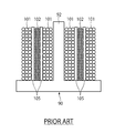
- FIG. 4 is a cross-sectional view of a prior art transformer. Each of the primary winding 101 and the secondary winding 102 shown in FIG. 4 is covered with an insulating member.
- the current flowing in the primary winding 101 or the secondary winding is caused by a so-called proximity effect in the mode shown in FIG.
- the currents flowing in the wire 102 repel each other, and the currents flowing in the windings 101 and 102 flow at positions separated from each other.
- the cross-sectional area through which the current flows in the windings 101 and 102 becomes small, and as a result, the resistance increases.
- the primary winding 101 or secondary located inside is affected by both the skin effect and the proximity effect. It becomes difficult for current to flow through the winding 102, and the resistance increases considerably. More specifically, in the aspect shown in FIG. 4, the primary winding 101 in the second row of the primary windings 101 in the three rows and the primary winding 101 not located at the upper and lower ends and the two rows in the three rows. Of the secondary windings 102, the secondary windings 102 in the second row and the secondary windings 102 that are not positioned at the upper and lower ends make it difficult for current to flow, and the resistance increases considerably.
- the present invention prevents the current flowing region from becoming extremely small due to the skin effect even when operated at a high frequency, and the cross-sectional area through which the current flows is small due to the proximity effect. By suppressing this, it is possible to efficiently pass a current, to reduce the size, and to provide a transformer that does not collapse.
- the transformer of the present invention is A primary coil pattern having a primary surface shape portion made up of a single surface shape, a secondary coil pattern having a secondary surface shape portion made up of a single surface shape, and between the primary coil pattern and the secondary coil pattern A coil portion having an insulating layer disposed, The primary coil pattern and the insulating layer are in intimate contact, The insulating layer and the secondary coil pattern are in close contact.
- the coil portion may be wound so as to have a column shape.
- the primary coil pattern and the secondary coil pattern are viewed along the radial direction of the coil portion, the primary coil pattern, the order of the secondary coil pattern or the secondary coil pattern, the primary coil pattern They may be arranged in order.
- the insulating layer has an insulating film disposed between the primary coil pattern and the secondary coil pattern,
- the primary coil pattern is provided on one surface of the insulating film,
- the secondary coil pattern may be provided on the other surface of the insulating film.
- the coil part is wound in a columnar shape
- the ratio of the number of times of winding of the primary coil pattern and the number of times of winding of the secondary coil pattern may be 1: n (“n” is an integer of 2 or more) or n: 1.
- the insulating layer may include a primary insulating layer formed so as to cover the primary coil pattern or a secondary insulating layer formed so as to cover the secondary coil pattern.
- the insulating layer may include a primary insulating layer formed so as to cover the primary coil pattern and a secondary insulating layer formed so as to cover the secondary coil pattern.
- the coil part is wound in a columnar shape
- the primary coil pattern has a primary protruding portion that protrudes in a direction including a component in a direction orthogonal to the winding direction of the coil portion from the primary surface shape portion
- the secondary coil pattern has a secondary protrusion protruding in a direction including a component in a direction orthogonal to the winding direction of the coil part from the secondary surface shape part
- the direction in which the primary protrusion protrudes from the primary surface shape portion and the direction in which the secondary protrusion protrudes from the secondary surface shape portion may have components opposite to each other.
- the coil part is wound in a columnar shape
- a heat radiating member made of an insulating material may be provided at a position on the direction side perpendicular to the winding direction of the coil portion with respect to the primary surface shape portion and adjacent to the primary surface shape portion.
- the coil part is wound in a columnar shape
- a heat dissipating member made of an insulating material may be provided at a position on the direction side perpendicular to the winding direction of the coil portion with respect to the secondary surface shape portion and adjacent to the secondary surface shape portion.
- the coil portion further includes a tertiary coil pattern having a tertiary surface shape portion composed of a single-layer surface shape,
- a tertiary coil pattern having a tertiary surface shape portion composed of a single-layer surface shape
- the transformer of the present invention is It further includes a core having a columnar portion made of a columnar shape, The coil part may be wound around the columnar part.
- the transformer of the present invention is You may further provide the cooling storage part which stored the antifreeze liquid in which the said coil part is immersed.
- a plurality of the secondary coil patterns are provided,
- the coil part is wound in a columnar shape,
- Each secondary coil pattern occupies a different area in a direction orthogonal to the winding direction of the coil part,
- Each secondary coil pattern has a secondary protrusion that protrudes in a direction including a component in a direction orthogonal to the winding direction of the coil part from the secondary surface shape part,
- the secondary protrusion of the secondary coil pattern may be connected to the secondary protrusion of another secondary coil pattern other than the secondary coil pattern.
- a primary coil pattern having a primary surface shape portion having a single layer shape and a secondary coil pattern having a secondary surface shape portion having a single layer shape are employed. For this reason, even if it is a case where it operates at a high frequency, it can prevent that the area
- the primary coil patterns and the secondary coil patterns are not adjacent to each other, so that it is possible to suppress a reduction in the cross-sectional area through which current flows due to the proximity effect.
- this invention can prevent that resistance becomes large by limiting the area
- the size of the transformer can be reduced.
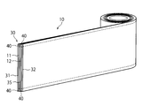
- FIG. 1 is a perspective view of a transformer according to a first aspect of an embodiment of the present invention.
- FIG. 2A is a simplified perspective view showing a transformer according to the second aspect of the embodiment of the present invention.
- FIG. 2B is a perspective view of a transformer according to the second aspect of the embodiment of the present invention.
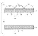
- FIG. 3A (a) is a plan view showing the primary coil pattern side by unfolding the coil portion of the transformer according to the second aspect of the embodiment of the present invention, and FIG. 3A (b) is an embodiment of the present invention. It is the top view which expand
- FIG. 3B (a) is a plan view showing the secondary coil pattern side by expanding the coil portion of the transformer according to the modification of the second aspect of the embodiment of the present invention
- FIG. 3B (b) It is the top view which expand
- FIG. 4 is a cross-sectional view of a prior art transformer.
- or FIG. 3B is a figure for demonstrating embodiment of this invention.
- the transformer 100 includes a core having a base portion, a columnar portion having a column shape extending from the base portion, and a coil portion 10 wound around the columnar portion and having a columnar shape. .
- description will be made using an embodiment provided with such a core, but it is sufficient that the coil portion 10 is wound in a columnar shape, and the core is not necessarily required.
- the coil portion 10 includes a primary coil pattern 11 having a primary surface shape portion 11a (see FIG. 3A (a)) having a single layer shape, and a secondary surface shape portion 12a (FIG. 3A (b)) having a single surface shape.
- the primary coil pattern 11 and the insulating layer 30 are in close contact with each other, and the insulating layer 30 and the secondary coil pattern 12 are in close contact with each other.
- the primary coil pattern 11 and the secondary coil pattern 12 are the order of the primary coil pattern 11 and the secondary coil pattern 12 or the secondary coil pattern 12.
- the primary coil patterns 11 are arranged in this order.
- the coil part 10 consists of copper, aluminum, gold
- the material of the coil part 10 should just be a conductor.
- the insulating layer 30 is made of, for example, polyimide and has plasticity.
- the insulating layer 30 includes both the primary insulating layer 31 formed so as to cover the primary coil pattern 11 and the secondary insulating layer 32 formed so as to cover the secondary coil pattern 12.
- the insulating layer 30 is formed of the primary insulating layer 31 formed so as to cover the primary coil pattern 11 or the secondary insulating layer 32 formed so as to cover the secondary coil pattern 12. It is also possible to adopt an embodiment having either one.
- the insulating layer 30 may include a primary insulating layer 31 formed so as to cover the primary coil pattern 11, and the outermost secondary coil pattern 12 may be covered with an end insulating layer.
- the insulating layer 30 may have a secondary insulating layer 32 formed so as to cover the secondary coil pattern 12, and in this case, the innermost primary coil pattern 11. Is covered with the end insulating layer.
- the coil part 10 has the tertiary coil pattern which has the tertiary surface shape part which consists of a single-layer surface shape, and the quaternary surface shape part which consists of a single-surface shape other than the primary coil pattern 11 and the secondary coil pattern 12.
- a quaternary coil pattern may have an l-order coil pattern having a l-order surface shape portion composed of a single-layer surface shape (“l” is an integer).
- the coil part 10 has the primary coil pattern 11, the secondary coil pattern 12, and the tertiary coil pattern
- the primary coil pattern 11 when it sees along the radial direction of the coil part 10, the primary coil pattern 11, the secondary coil pattern 12
- the tertiary coil pattern is arranged in the order of the primary coil pattern 11, the secondary coil pattern 12, and the tertiary coil pattern.
- a secondary coil When the primary coil pattern 11, the secondary coil pattern 12, and the tertiary coil pattern are seen along the radial direction of the coil part 10, a tertiary coil pattern, a secondary coil
- the pattern 12 and the primary coil pattern 11 may be arranged in this order.
- the coil unit 10 includes the primary coil pattern 11 and the secondary coil pattern 12, a tertiary coil pattern having a tertiary surface shape portion having a single layer shape, and a quaternary surface shape having a single layer shape.
- a quaternary coil pattern having a portion,..., A primary coil pattern having a primary surface shape portion having a single-layer surface shape. 11 and a secondary coil pattern 12 will be used.
- the coil unit 10 includes the primary coil pattern 11 and the secondary coil pattern 12
- the primary coil pattern 11 is provided on the insulating film 38
- the secondary coil pattern 12 is provided on another insulating film 39.
- a mode in which the primary coil pattern 11, the insulating film 38, the secondary coil pattern 12, and the insulating film 39 are arranged in this order can be used (see FIG. 1).
- the insulating layer 30 is the insulating film 35 arrange
- the primary coil pattern 11 is provided on the surface (one surface) of the insulating film 35
- the secondary coil pattern 12 is provided on the back surface (the other surface) of the insulating film 35. (See FIGS. 2A, 2B and 3A (a) (b)).
- each of the primary coil pattern 11 and the secondary coil pattern 12 is provided in the insulating film 35, for example by printing or bonding.
- FIG. 2A is a perspective view schematically showing the transformer 100 according to the second aspect of the embodiment of the present invention
- FIG. 2B is a diagram of the transformer 100 according to the second aspect of the embodiment of the present invention. It is a perspective view.
- the primary insulating layer 31 and a heat radiating member 40 described later are omitted in order to simply show the configuration of the transformer 100.
- FIG. 3A (a) is a plan view showing the primary coil pattern 11 side by unfolding the coil portion 10 of the transformer 100 according to the second aspect of the present embodiment
- the primary coil pattern 11 is provided with two or more, for example, and each primary coil pattern 11 is in the winding direction (left-right direction of FIG. 3A (a)) of the coil part 10. It occupies different areas (three different areas in the mode shown in FIG. 3A), and a mode in which only one secondary coil pattern 12 is provided can be used (see FIG. 3A (b)).
- this aspect is an example to the last, and is not limited to the said aspect.
- each primary coil pattern 11 is wound around the columnar part.
- the ratio of the number of times of winding and the number of times of winding of the secondary coil pattern 12 around the columnar portion may be 1: n (“n” is an integer of 2 or more).
- the ratio of the number of times each primary coil pattern 11 is wound around the columnar part and the number of times the secondary coil pattern 12 is wound around the columnar part is 1: 3. More specifically, as shown in FIGS. 3A (a) and 3 (b), three primary coil patterns 11 are formed on the surface side of the insulating film 35 of the coil portion 10. On the other hand, one secondary coil pattern 12 is formed on the back side of the insulating film 35 of the coil portion 10. In the present embodiment, each primary coil pattern 11 of the coil portion 10 is wound so as to rotate once around the columnar portion, and the secondary coil pattern 12 of the coil portion 10 is wound around three times around the columnar portion. It is.
- the ratio of the number of times each primary coil pattern 11 is wound around the columnar portion and the number of times the secondary coil pattern 12 is wound around the columnar portion is 1: 3.
- the upper left primary surface shape portion 11a located on the left side, the upper left primary surface shape portion 11a located in the middle, and the primary surface shape portion 11a located on the right side See arrow A1 in FIG. 3A
- the upper right side of the primary surface shape portion 11a located on the left side, the upper right side of the primary surface shape portion 11a located in the middle, and the primary surface located on the right side What is necessary is just to connect with the upper right of the shape part 11a (refer arrow A 2 of FIG. 3A (a)).
- each secondary coil pattern 12 f and 12 s is orthogonal to the winding direction of the coil portion 10 (FIG. 3B). Different areas may be occupied in the vertical direction of (a).
- each secondary coil pattern 12 f , 12 s is a component in the direction perpendicular to the winding direction of the coil portion 10 from the secondary surface shape portions 12 a f , 12 a s (vertical direction in FIG. 3B (a)).
- a secondary protrusion protruding in a direction including the secondary protrusion of the secondary coil pattern 12 f and a secondary protrusion of another secondary coil pattern 12 s other than the secondary coil pattern 12 f Can be connected. More specifically, when the coil part 10 is wound, the secondary protrusion part located outside (for example, the secondary protrusion part located on the right side in FIG. 3B (a)) and the coil part 10 are wound. What is necessary is just to connect the secondary protrusion part (For example, the secondary protrusion part located in the left side in FIG. 3B (a)) located inward (refer arrow A3 of FIG. 3B (a)). By using such an aspect, the number of turns of the secondary coil pattern 12 can be increased, which is beneficial. 3B (a) and (b), the ratio between the number of times each primary coil pattern 11 is wound around the columnar portion and the number of times the secondary coil pattern 12 is wound around the columnar portion. However, it is 1: 2.
- each primary coil pattern 11 may be provided, and each primary coil pattern 11 may occupy different regions in a direction orthogonal to the winding direction of the coil portion 10. And in this case, each primary coil pattern 11 has a primary protrusion part which protruded in the direction containing the component of the direction orthogonal to the winding direction of the coil part 10 from the primary surface shape part 11a, and the primary protrusion of the primary coil pattern 11 And a primary protrusion of another primary coil pattern 11 other than the primary coil pattern 11 may be connected.
- a primary protrusion that is located outward when the coil part 10 is wound may be connected to a primary protrusion that is located inward when the coil part 10 is wound.
- the insulating layer 30 is not limited to the aspect having both the primary insulating layer 31 and the secondary insulating layer 32, and the insulating layer 30 has only the primary insulating layer 31 or only the secondary insulating layer 32. It may be.
- the insulating layer 30 has only the primary insulating layer 31, the outermost secondary coil pattern 12 is covered with the end insulating layer, and the insulating layer 30 has only the secondary insulating layer 32. In this case, the innermost primary coil pattern 11 is covered with the end insulating layer.
- the insulating layer 30 includes the insulating film 35 disposed between the primary coil pattern 11 and the secondary coil pattern 12, and the primary coil pattern 11 is provided on the surface of the insulating film 35.
- the secondary coil pattern 12 is provided on the back surface of the insulating film 35.
- a separation insulating layer that is a separate body from the primary coil pattern 11 and the secondary coil pattern 12 may be provided between the pattern 12 and the primary coil pattern 11 (third aspect).
- a separation insulating layer is used in place of the insulating film 35 provided on the front surface and the back surface of each of the primary coil pattern 11 and the secondary coil pattern 12 used in the second aspect. It will be.
- each of the primary insulating layer 31, the secondary insulating layer 32, the insulating film 35, the end insulating layer and the separation insulating layer may be made of the same material or different materials. May be.
- a polyimide film can be given as an example of what is used for the primary insulating layer 31, the secondary insulating layer 32, the insulating film 35, the end insulating layer, and the insulating layer for separation.
- the primary coil pattern 11 protrudes from the primary surface shape portion 11a in a direction including a component perpendicular to the winding direction of the coil portion 10 (vertical direction in FIG. 3A (a)).
- the secondary coil pattern 12 includes components in a direction (vertical direction in FIG. 3A (b)) perpendicular to the winding direction of the coil part 10 from the secondary surface shape part 12a. It may have a secondary protrusion that protrudes in the direction and also serves as a “lead line”.
- the direction in which the primary protrusion protrudes from the primary surface shape portion 11a (the direction toward the upper side of FIG. 3A (a)) and the direction in which the secondary protrusion protrudes from the secondary surface shape portion 12a (FIG.
- the direction orthogonal to the winding direction of the coil part 10 is a direction where the axis
- Each of the primary protrusion and the secondary protrusion has a cross-sectional area that matches the capacity of the primary coil pattern 11 and the secondary coil pattern 12.
- the cross-sectional areas of the primary protrusion and the secondary protrusion are slightly smaller than the cross-sectional areas of the primary coil pattern 11 and the secondary coil pattern 12. Even if it is such an aspect, since a primary protrusion part and a secondary protrusion part are each exposed outside and are easy to cool, it is hard to produce a trouble at the time of flowing an electric current.
- the position on the direction side perpendicular to the winding direction of the coil portion 10 with respect to the primary surface shape portion 11a and adjacent to the primary surface shape portion 11a (this embodiment In the embodiment, the heat dissipating member 40 made of an insulating material is provided on both the upper and lower sides of the primary surface shape portion 11a.
- the position on the direction side perpendicular to the winding direction of the coil portion 10 with respect to the secondary surface shape portion 12a and the position adjacent to the secondary surface shape portion 12a (in this embodiment, the shape of the secondary surface)
- a heat radiating member 40 made of an insulating material is provided on both the upper and lower sides of the portion 12a.
- the heat radiating member 40 is made of, for example, ceramic, sapphire, diamond, or the like.
- a primary coil pattern 11 having a primary surface shape portion 11a having a single surface shape and a secondary coil pattern 12 having a secondary surface shape portion 12a having a single surface shape are employed. (See FIGS. 3A (a) and 3 (b)). For this reason, even if it is a case where it operates at a high frequency, it can prevent that the area
- the primary surface shape portion 11a and the secondary surface shape portion 12a can take a large area in which current flows, so that the area in which current flows can be prevented from becoming extremely small.
- primary coil patterns 11 and secondary coil patterns 12 do not adjoin, and the primary coil pattern 11 and the secondary coil pattern 12 follow the radial direction of the coil part 10. Therefore, it is possible to suppress a reduction in the cross-sectional area through which current flows due to the proximity effect.
- this Embodiment it can prevent that resistance becomes large by limiting the area
- the insulating layer 30 which consists of a polyimide film etc. is provided between the primary coil pattern 11 and the secondary coil pattern 12, (refer FIG.1 and FIG.2B), There is no need to use the layered paper 105 as in the prior art.
- the primary coil pattern 11 having the primary surface shape portion 11a having a single layer shape and the secondary coil pattern 12 having the secondary surface shape portion 12a having a single layer shape are adopted, the conventional winding There is no useless space between the lines 101 and 102, and it is not necessary to use an end filler.
- the size of the transformer 100 can be reduced.
- the windings 101 and 102 are not used as in the conventional case, the windings m and m (where “m” is an integer) are wound halfway as in the conventional windings 101 and 102.
- the windings 101 and 102 do not collapse as in the conventional case.
- the primary coil pattern 11 is provided on the surface of the insulating film 35, and the secondary coil pattern 12 is provided on the back surface of the insulating film 35 (FIGS. 2B and 2C).
- the insulating layer 30 includes a primary insulating layer 31 formed so as to cover the primary coil pattern 11 and / or a secondary insulating layer 32 formed so as to cover the secondary coil pattern 12.
- the ratio of the number of times each primary coil pattern 11 is wound around the columnar part to the number of times the secondary coil pattern 12 is wound around the columnar part is 1:
- n is an integer of 2 or more
- the space can be used effectively, which is preferable.
- the primary coil pattern 11 is provided on the surface of the insulating film 35 and the secondary coil pattern 12 is provided on the back surface of the insulating film 35.
- the ratio of the number of times the primary coil pattern 11 is wound and the number of times the secondary coil pattern 12 is wound is not 1: n or n: 1, it is not used on the front surface or the back surface on the insulating film 35. A space is inevitably generated, resulting in a useless space.
- the ratio of the number of times the primary coil pattern 11 is wound and the number of times the secondary coil pattern 12 is wound is 1: n or n: 1, the front and back surfaces on the insulating film 35 are effective. It can be used for.
- the insulating layer 30 includes a primary insulating layer 31 formed so as to cover the primary coil pattern 11 and a secondary insulating layer 32 formed so as to cover the secondary coil pattern 12.
- a primary insulating layer 31 formed so as to cover the primary coil pattern 11
- a secondary insulating layer 32 formed so as to cover the secondary coil pattern 12.
- the insulating layer 30 is formed so as to cover the primary coil pattern 11, and the secondary insulating layer is formed so as to cover the secondary coil pattern 12.
- the direction in which the primary protrusion protrudes from the primary surface shape portion 11a (the direction toward the upper side of FIG. 3A (a)) and the direction in which the secondary protrusion protrudes from the secondary surface shape portion 12a (
- the protruding direction of the so-called “lead line” can be reversed.
- an external device such as a power source
- the heat radiating member 40 made of an insulating material is located at a position on the direction side orthogonal to the winding direction of the coil portion 10 with respect to the primary surface shape portion 11a and adjacent to the primary surface shape portion 11a.
- a heat dissipating member 40 made of an insulating material is provided at a position on the side perpendicular to the winding direction of the coil portion 10 with respect to the secondary surface shape portion 12a and adjacent to the secondary surface shape portion 12a.
- the heat of each of the primary coil pattern 11 and the secondary coil pattern 12 can be radiated through the heat radiating member 40.
- each electrical resistance of the primary coil pattern 11 and the secondary coil pattern 12 becomes high by heat_generation
- the cooling storage part which stored the antifreeze liquid in this Embodiment since the coil part 10 and a core can be cooled with an antifreeze liquid, the primary coil pattern 11 and the secondary coil pattern 12 are generated by heat generation. It can suppress more efficiently that each electrical resistance becomes high.
Landscapes
- Engineering & Computer Science (AREA)
- Power Engineering (AREA)
- Coils Of Transformers For General Uses (AREA)
Abstract
トランス100は、一層の面形状からなる一次面形状部11aを有する一次コイルパターン11と、一層の面形状からなる二次面形状部12aを有する二次コイルパターン12と、一次コイルパターン11と二次コイルパターン12との間に配置された絶縁層30と、を有するコイル部10を備える。一次コイルパターン11と絶縁層30とは密接し、絶縁層30と二次コイルパターン12とは密接する。
Description
本発明は、面形状からなるコイルパターンを有するトランスに関する。
従来から、コア90の柱形状部92の周囲に、一次巻線101及び二次巻線102をレヤ紙105や板状部を介して巻回したトランスが知られている(特開2012-164928号参照)。なお、図4は従来技術のトランスの横断面図であるが、図4に示した一次巻線101及び二次巻線102の各々は絶縁性部材で被覆されている。
しかしながら、上述したような巻線101,102を採用した従来のトランスを高周波数(例えば70kHz)で動作させる場合、表皮効果(Skin Effect)により、電流は巻線101,102の表面にしか流れない。このため、巻線101,102において電流の流れる断面積が小さくなってしまい、ひいては抵抗が増大してしまう。
また、一次巻線101同士及び二次巻線102同士では電流が同じ方向に流れるため、図4に示すような態様では、いわゆる近接効果によって、一次巻線101内を流れる電流同士又は二次巻線102内を流れる電流同士が互いに反発してしまい、各巻線101,102内に流れる電流が互いに離れた位置で流れてしまう。このように各巻線101,102内に流れる電流が互いに離れた位置で流れると、巻線101,102において電流の流れる断面積が小さくなってしまい、ひいては抵抗が増大してしまう。
特に図4に示すように3列以上の一次巻線101又は二次巻線102が巻かれる態様では、表皮効果と近接効果の両方の影響を受け、内側に位置する一次巻線101又は二次巻線102で電流が流れ難くなり、抵抗がかなり増大してしまう。より具体的には、図4に示した態様では、3列ある一次巻線101のうち2列目の一次巻線101であって上下の端部に位置しない一次巻線101及び3列ある二次巻線102のうち2列目の二次巻線102であって上下の端部に位置しない二次巻線102で電流が流れ難くなり、抵抗がかなり増大してしまう。
上述のように抵抗が増大してしまうと、巻線101,102の温度が上昇してしまい、さらに抵抗が大きくなってしまうという悪循環が発生してしまう。
また、近年、トランスの小型化が求められているところ、従来技術では、厚さが50μm程のレヤ紙105が存在すること、断面積が円形の巻線101,102同士の間に無駄な空間ができること等によって、トランスのサイズを小さくするのが困難という問題もあった。
また、巻線101,102が終了すると、次の巻線101,102を巻く前に、終了した巻線101,102の末端部にエンドフィラーを設ける必要があるが、このようにエンドフィラーを設けるための空間自体が無駄であった。さらには、巻線101,102がm回転(「m」は整数である。)巻ききる前の途中で終了してしまうと、m回転巻ききる前の位置にエンドフィラーを設け、その後で次の巻線101,102を巻くことになるが、このようにm回転巻ききる前の位置にエンドフィラーを設けて次の巻線101,102を巻くと、次の巻線101,102が崩れてしまう可能性もあった。
以上のような点に鑑み、本発明は、高周波数で動作させた場合でも表皮効果によって電流が流れる領域が極端に小さくなってしまうことを防止するとともに、近接効果で電流の流れる断面積が小さくなってしまうことを抑えることで電流を効率よく流すことができ、また大きさを小型にすることができ、さらには崩れるおそれもないトランスを提供する。
本発明のトランスは、
一層の面形状からなる一次面形状部を有する一次コイルパターンと、一層の面形状からなる二次面形状部を有する二次コイルパターンと、前記一次コイルパターンと前記二次コイルパターンとの間に配置された絶縁層と、を有するコイル部を備え、
前記一次コイルパターンと前記絶縁層とは密接し、
前記絶縁層と前記二次コイルパターンとは密接する。
一層の面形状からなる一次面形状部を有する一次コイルパターンと、一層の面形状からなる二次面形状部を有する二次コイルパターンと、前記一次コイルパターンと前記二次コイルパターンとの間に配置された絶縁層と、を有するコイル部を備え、
前記一次コイルパターンと前記絶縁層とは密接し、
前記絶縁層と前記二次コイルパターンとは密接する。
本発明のトランスにおいて、
前記コイル部は柱形状になるように巻かれてもよい。
前記コイル部は柱形状になるように巻かれてもよい。
本発明のトランスにおいて、
前記一次コイルパターンと前記二次コイルパターンは、前記コイル部の径方向に沿って見たときに、前記一次コイルパターン、前記二次コイルパターンの順番又は前記二次コイルパターン、前記一次コイルパターンの順番に配置されてもよい。
前記一次コイルパターンと前記二次コイルパターンは、前記コイル部の径方向に沿って見たときに、前記一次コイルパターン、前記二次コイルパターンの順番又は前記二次コイルパターン、前記一次コイルパターンの順番に配置されてもよい。
本発明のトランスにおいて、
前記絶縁層は、前記一次コイルパターンと前記二次コイルパターンの間に配置された絶縁性フィルムを有し、
前記一次コイルパターンは前記絶縁性フィルムの一方の面に設けられ、
前記二次コイルパターンは前記絶縁性フィルムの他方の面に設けられてもよい。
前記絶縁層は、前記一次コイルパターンと前記二次コイルパターンの間に配置された絶縁性フィルムを有し、
前記一次コイルパターンは前記絶縁性フィルムの一方の面に設けられ、
前記二次コイルパターンは前記絶縁性フィルムの他方の面に設けられてもよい。
本発明のトランスにおいて、
前記コイル部は柱形状になるように巻かれ、
前記一次コイルパターンの巻かれる回数と、前記二次コイルパターンの巻かれる回数の比率が、1:n(「n」は2以上の整数)又はn:1になってもよい。
前記コイル部は柱形状になるように巻かれ、
前記一次コイルパターンの巻かれる回数と、前記二次コイルパターンの巻かれる回数の比率が、1:n(「n」は2以上の整数)又はn:1になってもよい。
本発明のトランスにおいて、
前記絶縁層は、前記一次コイルパターンを覆うようにして形成された一次絶縁層又は前記二次コイルパターンを覆うようにして形成された二次絶縁層を有してもよい。
前記絶縁層は、前記一次コイルパターンを覆うようにして形成された一次絶縁層又は前記二次コイルパターンを覆うようにして形成された二次絶縁層を有してもよい。
本発明のトランスにおいて、
前記絶縁層は、前記一次コイルパターンを覆うようにして形成された一次絶縁層及び前記二次コイルパターンを覆うようにして形成された二次絶縁層を有してもよい。
前記絶縁層は、前記一次コイルパターンを覆うようにして形成された一次絶縁層及び前記二次コイルパターンを覆うようにして形成された二次絶縁層を有してもよい。
本発明のトランスにおいて、
前記コイル部は柱形状になるように巻かれ、
前記一次コイルパターンは、前記一次面形状部から前記コイル部の巻き方向に直交する方向の成分を含む方向で突出した一次突出部を有し、
前記二次コイルパターンは、前記二次面形状部から前記コイル部の巻き方向に直交する方向の成分を含む方向で突出した二次突出部を有し、
前記一次突出部が前記一次面形状部から突出する向きと、前記二次突出部が前記二次面形状部から突出する向きとは、互いに逆向きの成分を有してもよい。
前記コイル部は柱形状になるように巻かれ、
前記一次コイルパターンは、前記一次面形状部から前記コイル部の巻き方向に直交する方向の成分を含む方向で突出した一次突出部を有し、
前記二次コイルパターンは、前記二次面形状部から前記コイル部の巻き方向に直交する方向の成分を含む方向で突出した二次突出部を有し、
前記一次突出部が前記一次面形状部から突出する向きと、前記二次突出部が前記二次面形状部から突出する向きとは、互いに逆向きの成分を有してもよい。
本発明のトランスにおいて、
前記コイル部は柱形状になるように巻かれ、
前記一次面形状部に対して前記コイル部の巻き方向に直交する方向側の位置であって前記一次面形状部に隣接する位置に、絶縁材料からなる放熱部材が設けられてもよい。
前記コイル部は柱形状になるように巻かれ、
前記一次面形状部に対して前記コイル部の巻き方向に直交する方向側の位置であって前記一次面形状部に隣接する位置に、絶縁材料からなる放熱部材が設けられてもよい。
本発明のトランスにおいて、
前記コイル部は柱形状になるように巻かれ、
前記二次面形状部に対して前記コイル部の巻き方向に直交する方向側の位置であって前記二次面形状部に隣接する位置に、絶縁材料からなる放熱部材が設けられてもよい。
前記コイル部は柱形状になるように巻かれ、
前記二次面形状部に対して前記コイル部の巻き方向に直交する方向側の位置であって前記二次面形状部に隣接する位置に、絶縁材料からなる放熱部材が設けられてもよい。
本発明のトランスにおいて、
前記コイル部は、一層の面形状からなる三次面形状部を有する三次コイルパターンをさらに有し、
前記一次コイルパターン、前記二次コイルパターン及び前記三次コイルパターンは、前記コイル部の径方向に沿って見たときに、前記一次コイルパターン、前記二次コイルパターン、前記三次コイルパターンの順番又は前記三次コイルパターン、前記二次コイルパターン、前記一次コイルパターンの順番に配置されてもよい。
前記コイル部は、一層の面形状からなる三次面形状部を有する三次コイルパターンをさらに有し、
前記一次コイルパターン、前記二次コイルパターン及び前記三次コイルパターンは、前記コイル部の径方向に沿って見たときに、前記一次コイルパターン、前記二次コイルパターン、前記三次コイルパターンの順番又は前記三次コイルパターン、前記二次コイルパターン、前記一次コイルパターンの順番に配置されてもよい。
本発明のトランスは、
柱形状からなる柱形状部を有するコアをさらに備え、
前記コイル部は前記柱形状部に巻き付けられてもよい。
柱形状からなる柱形状部を有するコアをさらに備え、
前記コイル部は前記柱形状部に巻き付けられてもよい。
本発明のトランスは、
前記コイル部が浸される不凍液を貯留した冷却貯留部をさらに備えてもよい。
前記コイル部が浸される不凍液を貯留した冷却貯留部をさらに備えてもよい。
本発明のトランスにおいて、
前記二次コイルパターンが複数設けられ、
前記コイル部は柱形状になるように巻かれ、
各二次コイルパターンは、前記コイル部の巻き方向に直交する方向において異なる領域を占め、
各二次コイルパターンが、前記二次面形状部から前記コイル部の巻き方向に直交する方向の成分を含む方向で突出した二次突出部を有し、
前記二次コイルパターンの前記二次突出部と、当該二次コイルパターン以外の別の二次コイルパターンの前記二次突出部とが接続されてもよい。
前記二次コイルパターンが複数設けられ、
前記コイル部は柱形状になるように巻かれ、
各二次コイルパターンは、前記コイル部の巻き方向に直交する方向において異なる領域を占め、
各二次コイルパターンが、前記二次面形状部から前記コイル部の巻き方向に直交する方向の成分を含む方向で突出した二次突出部を有し、
前記二次コイルパターンの前記二次突出部と、当該二次コイルパターン以外の別の二次コイルパターンの前記二次突出部とが接続されてもよい。
本発明のコイル部では、一層の面形状からなる一次面形状部を有する一次コイルパターンと、一層の面形状からなる二次面形状部を有する二次コイルパターンが採用されている。このため、高周波数で動作させた場合であっても表皮効果によって電流が流れる領域が極端に小さくなってしまうことを防止することができる。
また、本発明のコイル部では、一次コイルパターン同士及び二次コイルパターン同士が隣接することがないので、近接効果で電流の流れる断面積が小さくなってしまうことを抑えることができる。
これらのことから、本発明によれば、コイル部を流れる電流の領域が限定されることで抵抗が大きくなることを防止することができ、電流を効率よく流すことができる。
また、本発明のコイル部では、一次コイルパターンと二次コイルパターンとの間に絶縁層が設けられているので、従来のようにレヤ紙を用いる必要がない。
また、一層の面形状からなる一次面形状部を有する一次コイルパターンと、一層の面形状からなる二次面形状部を有する二次コイルパターンが採用されているので、従来の巻線のように互いの間に無駄な空間ができるもない。
これらのことから、本発明によれば、トランスのサイズを小さくすることができる。
実施の形態
《構成》
《構成》
以下、本発明に係るトランスの実施の形態について、図面を参照して説明する。ここで、図1乃至図3Bは本発明の実施の形態を説明するための図である。
本実施の形態のトランス100は、基部と、基部から延びた柱形状からなる柱形状部とを有するコアと、柱形状部に巻き付けられ、柱形状になったコイル部10と、を備えている。なお、本実施の形態では、このようなコアを備えた態様を用いて説明するが、コイル部10が柱形状になるように巻かれていれば十分であり、コアは必ずしも必要ではない。
コイル部10は、一層の面形状からなる一次面形状部11a(図3A(a)参照)を有する一次コイルパターン11と、一層の面形状からなる二次面形状部12a(図3A(b)参照)を有する二次コイルパターン12と、一次コイルパターン11と二次コイルパターン12との間に配置された絶縁層30と、を有している。そして、一次コイルパターン11と絶縁層30とは密接し、当該絶縁層30と二次コイルパターン12とは密接する。本実施の形態では、コイル部10の径方向に沿って見たときに、一次コイルパターン11と二次コイルパターン12は、一次コイルパターン11、二次コイルパターン12の順番又は二次コイルパターン12、一次コイルパターン11の順番になるように配置されている。
なお、コイル部10は例えば銅・アルミ・金・銀等からなるが、コイル部10の材料は導体であればよい。また、絶縁層30は、例えばポリイミド等からなり、可塑性を有している。
本実施の形態では、絶縁層30が、一次コイルパターン11を覆うようにして形成された一次絶縁層31と、二次コイルパターン12を覆うようにして形成された二次絶縁層32の両方を有する態様を採用することができる。
また、このような態様と異なり、絶縁層30が、一次コイルパターン11を覆うようにして形成された一次絶縁層31又は二次コイルパターン12を覆うようにして形成された二次絶縁層32のいずれかを有する態様を採用することもできる。一例として、絶縁層30が、一次コイルパターン11を覆うようにして形成された一次絶縁層31を有し、最も外方の二次コイルパターン12は端部絶縁層で覆われてもよい。また、別の例として、絶縁層30が、二次コイルパターン12を覆うようにして形成された二次絶縁層32を有してもよく、この場合には、最も内方の一次コイルパターン11が端部絶縁層で覆われることとなる。
ところで、コイル部10は、一次コイルパターン11及び二次コイルパターン12の他に、一層の面形状からなる三次面形状部を有する三次コイルパターン、一層の面形状からなる四次面形状部を有する四次コイルパターン、・・・・、一層の面形状からなるl次面形状部を有するl次コイルパターンを有していてもよい(なお「l」は整数である。)。例えば、コイル部10が一次コイルパターン11、二次コイルパターン12及び三次コイルパターンを有する場合には、コイル部10の径方向に沿って見たときに、一次コイルパターン11、二次コイルパターン12及び三次コイルパターンが一次コイルパターン11、二次コイルパターン12、三次コイルパターンの順番に配置されている。なお、このような態様に限られることはなく、一次コイルパターン11、二次コイルパターン12及び三次コイルパターンは、コイル部10の径方向に沿って見たときに、三次コイルパターン、二次コイルパターン12、一次コイルパターン11の順番に配置されてもよい。
上述したように、コイル部10は、一次コイルパターン11及び二次コイルパターン12の他に、一層の面形状からなる三次面形状部を有する三次コイルパターン、一層の面形状からなる四次面形状部を有する四次コイルパターン、・・・・、一層の面形状からなるl次面形状部を有するl次コイルパターンを有していてもよいが、以下では、コイル部10が、一次コイルパターン11及び二次コイルパターン12を有する態様を用いて説明する。
コイル部10が、一次コイルパターン11及び二次コイルパターン12を有する第一の態様としては、一次コイルパターン11が絶縁性フィルム38に設けられ、二次コイルパターン12が別の絶縁性フィルム39に設けられ、一次コイルパターン11、絶縁性フィルム38、二次コイルパターン12及び絶縁性フィルム39の順番に配置された態様を用いることができる(図1参照)。
コイル部10が、一次コイルパターン11及び二次コイルパターン12を有する第二の態様としては、絶縁層30が、一次コイルパターン11と二次コイルパターン12の間に配置された絶縁性フィルム35を有し、一次コイルパターン11が絶縁性フィルム35の表面(一方の面)に設けられ、二次コイルパターン12が絶縁性フィルム35の裏面(他方の面)に設けられている態様を用いることができる(図2A、図2B及び図3A(a)(b)参照)。なお、この第二の態様において、一次コイルパターン11及び二次コイルパターン12の各々は、例えば印刷や貼り合わせによって、絶縁性フィルム35に設けられる。
ちなみに、図2Aは、本発明の実施の形態の第二の態様によるトランス100を簡略化して示した斜視図であり、図2Bは、本発明の実施の形態の第二の態様によるトランス100の斜視図である。図2Aについて説明すると、図2Aでは、トランス100の構成を簡略に示すために、一次絶縁層31及び後述する放熱部材40を省略している。また、図3A(a)は、本実施の形態の第二の態様によるトランス100のコイル部10を展開して一次コイルパターン11側を示した平面図であり、図3A(b)は、本実施の形態の第二の態様によるトランス100のコイル部10を展開して二次コイルパターン12側を示した平面図である。
この態様では、図3A(a)(b)に示すように、例えば一次コイルパターン11が複数設けられ、各一次コイルパターン11がコイル部10の巻き方向(図3A(a)の左右方向)において異なる領域(図3A(a)に示した態様では異なる3つの領域)を占め、二次コイルパターン12は一つだけ設けられる態様を用いることができる(図3A(b)参照)。なお、この態様もあくまでも一例であり、当該態様に限定されることはない。
このように一次コイルパターン11が複数設けられ、各一次コイルパターン11がコイル部10の巻き方向において異なる領域を占める態様を用いた場合には、各一次コイルパターン11が柱形状部の周りで巻かれる回数と、二次コイルパターン12が柱形状部の周りで巻かれる回数の比率を、1:n(「n」は2以上の整数)とすることもできる。
図3A(a)(b)で示した態様では、各一次コイルパターン11が柱形状部の周りで巻かれる回数と、二次コイルパターン12が柱形状部の周りで巻かれる回数の比率が、1:3になっている。より具体的には、図3A(a)(b)に示すように、コイル部10の絶縁性フィルム35の表面側には、3つの一次コイルパターン11が形成されている。他方、コイル部10の絶縁性フィルム35の裏面側には、1つの二次コイルパターン12が形成されている。本実施の形態では、コイル部10の各一次コイルパターン11が柱形状部に1回転するようにして巻かれ、コイル部10の二次コイルパターン12が柱形状部に3回転するようにして巻かれている。このため、各一次コイルパターン11が柱形状部の周りで巻かれる回数と、二次コイルパターン12が柱形状部の周りで巻かれる回数の比率が、1:3になっている。なお、図3A(a)に示した態様では、例えば、左側に位置する一次面形状部11aの左上と、真ん中に位置する一次面形状部11aの左上と、右側に位置する一次面形状部11aの左上とを接続し(図3A(a)の矢印A1参照)、左側に位置する一次面形状部11aの右上と、真ん中に位置する一次面形状部11aの右上と、右側に位置する一次面形状部11aの右上とを接続すればよい(図3A(a)の矢印A2参照)。
なお、図3B(a)に示すように、二次コイルパターン12f,12sが複数設けられ、各二次コイルパターン12f,12sがコイル部10の巻き方向に直交する方向(図3B(a)の上下方向)において異なる領域を占めてもよい。そして、この場合、各二次コイルパターン12f,12sが、二次面形状部12af,12asからコイル部10の巻き方向に直交する方向(図3B(a)の上下方向)の成分を含む方向で突出した二次突出部を有し、二次コイルパターン12fの二次突出部と、当該二次コイルパターン12f以外の別の二次コイルパターン12sの二次突出部とを接続すればよい。より具体的には、コイル部10を巻いた際に外方に位置する二次突出部(例えば図3B(a)において右側に位置する二次突出部)と、コイル部10を巻いた際に内方に位置する二次突出部(例えば図3B(a)において左側に位置する二次突出部)とを接続すればよい(図3B(a)の矢印A3参照)。このような態様を用いることで、二次コイルパターン12の巻き数を増やすことができ有益である。なお、図3B(a)(b)で示した態様では、各一次コイルパターン11が柱形状部の周りで巻かれる回数と、二次コイルパターン12が柱形状部の周りで巻かれる回数の比率が、1:2になっている。
なお、図示しないが、当該態様を一次コイルパターン11に適用することもできる。つまり、一次コイルパターン11が複数設けられ、各一次コイルパターン11がコイル部10の巻き方向に直交する方向において異なる領域を占めてもよい。そして、この場合、各一次コイルパターン11が、一次面形状部11aからコイル部10の巻き方向に直交する方向の成分を含む方向で突出した一次突出部を有し、一次コイルパターン11の一次突出部と、当該一次コイルパターン11以外の別の一次コイルパターン11の一次突出部とが接続されてもよい。より具体的には、コイル部10を巻いた際に外方に位置する一次突出部と、コイル部10を巻いた際に内方に位置する一次突出部とを接続すればよい。このような態様を用いることで、一次コイルパターン11の巻き数を増やすことができ有益である。
ちなみに、絶縁層30が一次絶縁層31と二次絶縁層32の両方を有している態様に限られることはなく、絶縁層30が一次絶縁層31のみ又は二次絶縁層32のみを有する態様であってもよい。絶縁層30が一次絶縁層31のみを有する場合には、最も外方の二次コイルパターン12は端部絶縁層で覆われ、絶縁層30が、絶縁層30が二次絶縁層32のみを有する場合には、最も内方の一次コイルパターン11が端部絶縁層で覆われることとなる。
上述した第二の態様では、絶縁層30が、一次コイルパターン11と二次コイルパターン12の間に配置された絶縁性フィルム35を有し、一次コイルパターン11が絶縁性フィルム35の表面に設けられ、二次コイルパターン12が絶縁性フィルム35の裏面に設けられている態様であったが、このような態様ではなく、一次コイルパターン11と二次コイルパターン12の間、及び、二次コイルパターン12と一次コイルパターン11の間に、一次コイルパターン11及び二次コイルパターン12とは別体になった離隔用絶縁層を設けることもできる(第三の態様)。この第三の態様では、第二の態様で用いられた一次コイルパターン11及び二次コイルパターン12の各々が表面及び裏面に設けられた絶縁性フィルム35の代わりに、離隔用絶縁層が用いられることとなる。
ちなみに、一次絶縁層31、二次絶縁層32、絶縁性フィルム35、端部絶縁層及び離隔用絶縁層の各々は、同じ材質のものから構成されてもよいし、異なる材質のものから構成されてもよい。一次絶縁層31、二次絶縁層32、絶縁性フィルム35、端部絶縁層及び離隔用絶縁層に用いられるものの一例としてはポリイミドフィルムを挙げることができる。
本実施の形態では、一次コイルパターン11は、一次面形状部11aからコイル部10の巻き方向に直交する方向(図3A(a)の上下方向)の成分を含む方向で突出し、いわゆる「口出し線」の役割を果たす一次突出部を有し、二次コイルパターン12は、二次面形状部12aからコイル部10の巻き方向に直交する方向(図3A(b)の上下方向)の成分を含む方向で突出し、やはり「口出し線」の役割を果たす二次突出部を有してもよい。そして、一次突出部が一次面形状部11aから突出する向き(図3A(a)の上側に向かった向き)と、二次突出部が二次面形状部12aから突出する向き(図3A(b)の下側に向かった向き)とは、互いに逆向きの成分を有してもよい。なお、本願において、「コイル部10の巻き方向に直交する方向」とは柱形状のコイル部10の軸が延在する方向であり、本実施の形態では柱形状部の軸が延在する方向である。
一次突出部及び二次突出部の各々は、一次コイルパターン11及び二次コイルパターン12の容量にあった断面積を有している。その一例としては、一次突出部及び二次突出部の各々の断面積は、一次コイルパターン11及び二次コイルパターン12の断面積よりもわずかに小さくなっている。このような態様であっても、一次突出部及び二次突出部は各々外部に露出されており冷却しやすいことから、電流を流す際に支障が出にくい。
図2Bに示すように、本実施の形態では、一次面形状部11aに対してコイル部10の巻き方向に直交する方向側の位置であって一次面形状部11aに隣接する位置(本実施の形態では一次面形状部11aの上下側の両方)に、絶縁材料からなる放熱部材40が設けられている。また、同様に、二次面形状部12aに対してコイル部10の巻き方向に直交する方向側の位置であって二次面形状部12aに隣接する位置(本実施の形態では二次面形状部12aの上下側の両方)に、絶縁材料からなる放熱部材40が設けられている。放熱部材40は例えばセラミック、サファイア、ダイヤモンド等からなっている。
なお、本実施の形態では、コイル部10及びコアが浸される不凍液を貯留した冷却貯留部をさらに設けてもよい。
《作用・効果》
次に、上述した構成からなる本実施の形態による作用・効果について説明する。
次に、上述した構成からなる本実施の形態による作用・効果について説明する。
本実施の形態のコイル部10では、一層の面形状からなる一次面形状部11aを有する一次コイルパターン11と、一層の面形状からなる二次面形状部12aを有する二次コイルパターン12が採用されている(図3A(a)(b)参照)。このため、高周波数で動作させた場合であっても表皮効果によって電流が流れる領域が極端に小さくなってしまうことを防止することができる。つまり、本実施の形態のように一層の面形状からなる一次面形状部11aや一層の面形状からなる二次面形状部12aでは、表皮効果が発生した場合であっても、一次面形状部11a及び二次面形状部12aのうち電流が流れる領域を大きくとることができるので、電流が流れる領域が極端に小さくなってしまうことを防止することができる。
また、本実施の形態のコイル部10では、一次コイルパターン11同士及び二次コイルパターン12同士が隣接することがなく、一次コイルパターン11と二次コイルパターン12がコイル部10の径方向に沿って見たときに順番に配置されているので、近接効果で電流の流れる断面積が小さくなってしまうことを抑えることができる。
これらのことから、本実施の形態によれば、コイル部10を流れる電流の領域が限定されることで抵抗が大きくなることを防止することができ、電流を効率よく流すことができる。
また、本実施の形態のコイル部10では、一次コイルパターン11と二次コイルパターン12との間に例えばポリイミドフィルム等からなる絶縁層30が設けられているので(図1及び図2B参照)、従来のようにレヤ紙105を用いる必要がない。
また、一層の面形状からなる一次面形状部11aを有する一次コイルパターン11と、一層の面形状からなる二次面形状部12aを有する二次コイルパターン12が採用されているので、従来の巻線101,102のように互いの間に無駄な空間ができるもなく、さらには、エンドフィラーを用いる必要もない。
これらのことから、本実施の形態によれば、トランス100のサイズを小さくすることができる。
さらに、本実施の形態では、従来のように巻線101,102を用いないので、従来の巻線101,102のようにm回転(「m」は整数である。)巻ききる前の途中で終了してしまうことはなく、従来のように巻線101,102が崩れてしまうということもない。
また、本実施の形態の第二の態様では、一次コイルパターン11が絶縁性フィルム35の表面に設けられ、二次コイルパターン12が絶縁性フィルム35の裏面に設けられている(図2B及び図3A(a)(b)参照)。さらに、絶縁層30が、一次コイルパターン11を覆うようにして形成された一次絶縁層31及び/又は二次コイルパターン12を覆うようにして形成された二次絶縁層32を有している。このように一次コイルパターン11、二次コイルパターン12及び絶縁層30が一体となっているので、コイル部10を、コアに巻き付けるだけで、簡単にトランス100を作ることができる。
また、本実施の形態の第二の態様において、各一次コイルパターン11が柱形状部の周りで巻かれる回数と、二次コイルパターン12が柱形状部の周りで巻かれる回数の比率が1:n(「n」は2以上の整数)となるようにした場合には(図3A(a)(b)及び図3B(a)(b)参照)、空間を有効活用することができ、好ましい。すなわち、本実施の形態の第二の態様のように、一次コイルパターン11が絶縁性フィルム35の表面に設けられ、二次コイルパターン12が絶縁性フィルム35の裏面に設けられている態様において、一次コイルパターン11の巻かれる回数と二次コイルパターン12の巻かれる回数の比率が1:n又はn:1になっていない場合には、絶縁性フィルム35上の表面又は裏面において利用されていない空間がどうしても発生してしまい、無駄な空間が生じてしまう。これに対して、一次コイルパターン11の巻かれる回数と二次コイルパターン12の巻かれる回数の比率を1:n又はn:1とした場合には、絶縁性フィルム35上の表面及び裏面を有効に活用することができる。
また、本実施の形態において、絶縁層30が、一次コイルパターン11を覆うようにして形成された一次絶縁層31と、二次コイルパターン12を覆うようにして形成された二次絶縁層32の両方を有する場合には、上記のようにレヤ紙105を用いる必要がなくなることで得られる効果の他、コイル部10が酸化してしまうことを防止することができ、ひいては、コイル部10の耐熱性能を上げることができる。
この点について説明する。一次コイルパターン11又は二次コイルパターン12のいずれかしか絶縁層30で覆わなかった場合、絶縁層30で覆われなかった方のコイルパターンが酸化してしまいやすくなる。そして、コイルパターンが酸化してしまうと、当該コイルパターンの耐熱性能が下がってしまう。これに対して、上述したように、絶縁層30が、一次コイルパターン11を覆うようにして形成された一次絶縁層31と、二次コイルパターン12を覆うようにして形成された二次絶縁層32の両方を有する場合には、コイル部10が酸化してしまうことを防止することができ、ひいては、コイル部10の耐熱性能を上げることができる。
本実施の形態において、一次突出部が一次面形状部11aから突出する向き(図3A(a)の上側に向かった向き)と、二次突出部が二次面形状部12aから突出する向き(図3A(b)の下側に向かった向き)とが、互いに逆向きの成分を有する態様を採用した場合には、いわゆる「口出し線」の突出している向きを逆向きにすることができる。この結果、一次突出部及び二次突出部に電源等の外部装置を接続しやすくすることができる。
また、本実施の形態において、一次面形状部11aに対してコイル部10の巻き方向に直交する方向側の位置であって一次面形状部11aに隣接する位置に、絶縁材料からなる放熱部材40が設けられ、二次面形状部12aに対してコイル部10の巻き方向に直交する方向側の位置であって二次面形状部12aに隣接する位置に、絶縁材料からなる放熱部材40が設けられた態様を採用した場合には(図2B参照)、一次コイルパターン11及び二次コイルパターン12の各々の熱を、放熱部材40を介して放熱することができる。このため、このような態様によれば、発熱によって一次コイルパターン11及び二次コイルパターン12の各々の電気抵抗が高くなることを抑制することができる。また、従来であれば、コイル部10を冷却するために風を送るための放熱装置が設けられていたことを考えると、本実施の形態によれば、そのような放熱装置を設ける必要がないので、放熱装置を設けた従来の態様と比較して、大きさを小さくすることができる。
また、本実施の形態で不凍液を貯留した冷却貯留部を設けた場合には、不凍液によって、コイル部10及びコアを冷却することができるので、発熱によって、一次コイルパターン11及び二次コイルパターン12の各々の電気抵抗が高くなることをより効率よく抑制することができる。
最後になったが、上述した各実施の形態の記載及び図面の開示は、特許請求の範囲に記載された発明を説明するための一例に過ぎず、上述した実施の形態の記載又は図面の開示によって特許請求の範囲に記載された発明が限定されることはない。
10 コイル部
11 一次コイルパターン
11a 一次面形状部
12 二次コイルパターン
12a 二次面形状部
30 絶縁層
31 一次絶縁層
32 二次絶縁層
35 絶縁性フィルム
40 放熱部材
90 コア
92 柱形状部
100 トランス
11 一次コイルパターン
11a 一次面形状部
12 二次コイルパターン
12a 二次面形状部
30 絶縁層
31 一次絶縁層
32 二次絶縁層
35 絶縁性フィルム
40 放熱部材
90 コア
92 柱形状部
100 トランス
Claims (14)
- 一層の面形状からなる一次面形状部を有する一次コイルパターンと、一層の面形状からなる二次面形状部を有する二次コイルパターンと、前記一次コイルパターンと前記二次コイルパターンとの間に配置された絶縁層と、を有するコイル部を備え、
前記一次コイルパターンと前記絶縁層とは密接し、
前記絶縁層と前記二次コイルパターンとは密接することを特徴とするトランス。 - 前記コイル部は柱形状になるように巻かれることを特徴とする請求項1に記載のトランス。
- 前記一次コイルパターンと前記二次コイルパターンは、前記コイル部の径方向に沿って見たときに、前記一次コイルパターン、前記二次コイルパターンの順番又は前記二次コイルパターン、前記一次コイルパターンの順番に配置されることを特徴とする請求項2に記載のトランス。
- 前記絶縁層は、前記一次コイルパターンと前記二次コイルパターンの間に配置された絶縁性フィルムを有し、
前記一次コイルパターンは前記絶縁性フィルムの一方の面に設けられ、
前記二次コイルパターンは前記絶縁性フィルムの他方の面に設けられていることを特徴とする請求項1乃至3のいずれか1項に記載のトランス。 - 前記コイル部は柱形状になるように巻かれ、
前記一次コイルパターンの巻かれる回数と、前記二次コイルパターンの巻かれる回数の比率が、1:n(「n」は2以上の整数)又はn:1になっていることを特徴とする請求項4に記載のトランス。 - 前記絶縁層は、前記一次コイルパターンを覆うようにして形成された一次絶縁層又は前記二次コイルパターンを覆うようにして形成された二次絶縁層を有することを特徴とする請求項1乃至5のいずれか1項に記載のトランス。
- 前記絶縁層は、前記一次コイルパターンを覆うようにして形成された一次絶縁層及び前記二次コイルパターンを覆うようにして形成された二次絶縁層を有することを特徴とする請求項6に記載のトランス。
- 前記コイル部は柱形状になるように巻かれ、
前記一次コイルパターンは、前記一次面形状部から前記コイル部の巻き方向に直交する方向の成分を含む方向で突出した一次突出部を有し、
前記二次コイルパターンは、前記二次面形状部から前記コイル部の巻き方向に直交する方向の成分を含む方向で突出した二次突出部を有し、
前記一次突出部が前記一次面形状部から突出する向きと、前記二次突出部が前記二次面形状部から突出する向きとは、互いに逆向きの成分を有することを特徴とする請求項1乃至7のいずれか1項に記載のトランス。 - 前記コイル部は柱形状になるように巻かれ、
前記一次面形状部に対して前記コイル部の巻き方向に直交する方向側の位置であって前記一次面形状部に隣接する位置に、絶縁材料からなる放熱部材が設けられることを特徴とする請求項1乃至8のいずれか1項に記載のトランス。 - 前記コイル部は柱形状になるように巻かれ、
前記二次面形状部に対して前記コイル部の巻き方向に直交する方向側の位置であって前記二次面形状部に隣接する位置に、絶縁材料からなる放熱部材が設けられることを特徴とする請求項1乃至9のいずれか1項に記載のトランス。 - 前記コイル部は、一層の面形状からなる三次面形状部を有する三次コイルパターンをさらに有し、
前記一次コイルパターン、前記二次コイルパターン及び前記三次コイルパターンは、前記コイル部の径方向に沿って見たときに、前記一次コイルパターン、前記二次コイルパターン、前記三次コイルパターンの順番又は前記三次コイルパターン、前記二次コイルパターン、前記一次コイルパターンの順番に配置されることを特徴とする請求項1乃至10のいずれか1項に記載のトランス。 - 柱形状からなる柱形状部を有するコアをさらに備え、
前記コイル部は前記柱形状部に巻き付けられることを特徴とする請求項1乃至11のいずれか1項に記載のトランス。 - 前記コイル部が浸される不凍液を貯留した冷却貯留部をさらに備えたことを特徴とする請求項1乃至12のいずれか1項に記載のトランス。
- 前記二次コイルパターンが複数設けられ、
前記コイル部は柱形状になるように巻かれ、
各二次コイルパターンは、前記コイル部の巻き方向に直交する方向において異なる領域を占め、
各二次コイルパターンが、前記二次面形状部から前記コイル部の巻き方向に直交する方向の成分を含む方向で突出した二次突出部を有し、
前記二次コイルパターンの前記二次突出部と、当該二次コイルパターン以外の別の二次コイルパターンの前記二次突出部とが接続されることを特徴とする請求項1乃至13のいずれか1項に記載のトランス。
Priority Applications (5)
| Application Number | Priority Date | Filing Date | Title |
|---|---|---|---|
| PCT/JP2012/083123 WO2014097455A1 (ja) | 2012-12-20 | 2012-12-20 | トランス |
| KR1020157014110A KR101638948B1 (ko) | 2012-12-20 | 2013-07-31 | 변압기 |
| JP2014552954A JP6054422B2 (ja) | 2012-12-20 | 2013-07-31 | トランス |
| PCT/JP2013/070730 WO2014097673A1 (ja) | 2012-12-20 | 2013-07-31 | トランス |
| CN201380061706.2A CN105122396B (zh) | 2012-12-20 | 2013-07-31 | 变压器 |
Applications Claiming Priority (1)
| Application Number | Priority Date | Filing Date | Title |
|---|---|---|---|
| PCT/JP2012/083123 WO2014097455A1 (ja) | 2012-12-20 | 2012-12-20 | トランス |
Publications (1)
| Publication Number | Publication Date |
|---|---|
| WO2014097455A1 true WO2014097455A1 (ja) | 2014-06-26 |
Family
ID=50977833
Family Applications (2)
| Application Number | Title | Priority Date | Filing Date |
|---|---|---|---|
| PCT/JP2012/083123 Ceased WO2014097455A1 (ja) | 2012-12-20 | 2012-12-20 | トランス |
| PCT/JP2013/070730 Ceased WO2014097673A1 (ja) | 2012-12-20 | 2013-07-31 | トランス |
Family Applications After (1)
| Application Number | Title | Priority Date | Filing Date |
|---|---|---|---|
| PCT/JP2013/070730 Ceased WO2014097673A1 (ja) | 2012-12-20 | 2013-07-31 | トランス |
Country Status (4)
| Country | Link |
|---|---|
| JP (1) | JP6054422B2 (ja) |
| KR (1) | KR101638948B1 (ja) |
| CN (1) | CN105122396B (ja) |
| WO (2) | WO2014097455A1 (ja) |
Families Citing this family (1)
| Publication number | Priority date | Publication date | Assignee | Title |
|---|---|---|---|---|
| KR200494694Y1 (ko) * | 2018-07-17 | 2021-12-01 | 최융 | 진공관 엠프의 출력트랜스포머 |
Citations (8)
| Publication number | Priority date | Publication date | Assignee | Title |
|---|---|---|---|---|
| JPS57119516U (ja) * | 1981-01-19 | 1982-07-24 | ||
| JPS5877210A (ja) * | 1981-10-31 | 1983-05-10 | Toshiba Corp | 変圧器 |
| JPH05299266A (ja) * | 1992-04-16 | 1993-11-12 | Sony Corp | 銅箔巻トランスの巻線構造及びその製造方法 |
| JPH07130549A (ja) * | 1993-11-05 | 1995-05-19 | Hitachi Ltd | 電気機器 |
| JPH07130554A (ja) * | 1991-04-26 | 1995-05-19 | Ryoda Sato | トランス及びその製造方法、及び抵抗溶接装置 |
| JP2000260634A (ja) * | 1999-03-11 | 2000-09-22 | Matsushita Electric Ind Co Ltd | 電磁コイルおよび乾式静止誘導器 |
| JP2008004774A (ja) * | 2006-06-22 | 2008-01-10 | Sekisui Chem Co Ltd | トランス及び高周波誘導加熱装置 |
| WO2011083533A1 (ja) * | 2010-01-06 | 2011-07-14 | 株式会社神戸製鋼所 | 複合型巻線素子ならびにこれを用いた変圧器、変圧システムおよびノイズカットフィルタ用複合型巻線素子 |
Family Cites Families (3)
| Publication number | Priority date | Publication date | Assignee | Title |
|---|---|---|---|---|
| JPH0672224U (ja) * | 1993-03-26 | 1994-10-07 | ミツミ電機株式会社 | トランス |
| JPH07211549A (ja) * | 1994-01-25 | 1995-08-11 | Matsushita Electric Works Ltd | 電磁装置 |
| JP2006340030A (ja) * | 2005-06-02 | 2006-12-14 | Hioki Ee Corp | フィルタ素子 |
-
2012
- 2012-12-20 WO PCT/JP2012/083123 patent/WO2014097455A1/ja not_active Ceased
-
2013
- 2013-07-31 KR KR1020157014110A patent/KR101638948B1/ko active Active
- 2013-07-31 JP JP2014552954A patent/JP6054422B2/ja active Active
- 2013-07-31 CN CN201380061706.2A patent/CN105122396B/zh active Active
- 2013-07-31 WO PCT/JP2013/070730 patent/WO2014097673A1/ja not_active Ceased
Patent Citations (8)
| Publication number | Priority date | Publication date | Assignee | Title |
|---|---|---|---|---|
| JPS57119516U (ja) * | 1981-01-19 | 1982-07-24 | ||
| JPS5877210A (ja) * | 1981-10-31 | 1983-05-10 | Toshiba Corp | 変圧器 |
| JPH07130554A (ja) * | 1991-04-26 | 1995-05-19 | Ryoda Sato | トランス及びその製造方法、及び抵抗溶接装置 |
| JPH05299266A (ja) * | 1992-04-16 | 1993-11-12 | Sony Corp | 銅箔巻トランスの巻線構造及びその製造方法 |
| JPH07130549A (ja) * | 1993-11-05 | 1995-05-19 | Hitachi Ltd | 電気機器 |
| JP2000260634A (ja) * | 1999-03-11 | 2000-09-22 | Matsushita Electric Ind Co Ltd | 電磁コイルおよび乾式静止誘導器 |
| JP2008004774A (ja) * | 2006-06-22 | 2008-01-10 | Sekisui Chem Co Ltd | トランス及び高周波誘導加熱装置 |
| WO2011083533A1 (ja) * | 2010-01-06 | 2011-07-14 | 株式会社神戸製鋼所 | 複合型巻線素子ならびにこれを用いた変圧器、変圧システムおよびノイズカットフィルタ用複合型巻線素子 |
Also Published As
| Publication number | Publication date |
|---|---|
| KR20150079894A (ko) | 2015-07-08 |
| CN105122396B (zh) | 2017-04-05 |
| CN105122396A (zh) | 2015-12-02 |
| JPWO2014097673A1 (ja) | 2017-01-12 |
| KR101638948B1 (ko) | 2016-07-12 |
| WO2014097673A1 (ja) | 2014-06-26 |
| JP6054422B2 (ja) | 2016-12-27 |
Similar Documents
| Publication | Publication Date | Title |
|---|---|---|
| JP6380745B2 (ja) | トランス | |
| JP6828555B2 (ja) | コイル部品およびその製造方法 | |
| JP4802615B2 (ja) | Lc複合部品 | |
| JP6509472B2 (ja) | トランス | |
| JP5974833B2 (ja) | コイル装置 | |
| CN112614646A (zh) | 电感器部件 | |
| JP2015002285A (ja) | コイル装置、電子装置及びコイル装置の制御方法 | |
| JP2018133500A (ja) | リアクトルおよびその製造方法 | |
| KR102486164B1 (ko) | 평면 변압기의 냉각 구조 | |
| JP6988432B2 (ja) | リアクトルユニット | |
| JP6054422B2 (ja) | トランス | |
| JP4946248B2 (ja) | リアクトル | |
| JP2013251451A (ja) | インダクタの複合フェライトコアとそれを用いたインダクタ | |
| JP6307449B2 (ja) | トランス | |
| JP2012009710A (ja) | コイル部品 | |
| JP6064943B2 (ja) | 電子機器 | |
| JP6961971B2 (ja) | コイル装置 | |
| CN112562993B (zh) | 一种带散热型绕组的电力电子磁性元件 | |
| JP2010073523A (ja) | 絶縁電線および、それを備えたリアクトル | |
| JP5516923B2 (ja) | リアクトル、およびコンバータ | |
| JP2014192359A (ja) | リアクトル | |
| US9570227B1 (en) | Magnetic excitation coil structure | |
| JP7468252B2 (ja) | コイル部品 | |
| WO2021100420A1 (ja) | リアクトル | |
| JP2007165729A (ja) | インダクタ |
Legal Events
| Date | Code | Title | Description |
|---|---|---|---|
| 121 | Ep: the epo has been informed by wipo that ep was designated in this application |
Ref document number: 12890626 Country of ref document: EP Kind code of ref document: A1 |
|
| NENP | Non-entry into the national phase |
Ref country code: DE |
|
| 122 | Ep: pct application non-entry in european phase |
Ref document number: 12890626 Country of ref document: EP Kind code of ref document: A1 |
|
| NENP | Non-entry into the national phase |
Ref country code: JP |