WO2014097420A1 - 無線通信装置 - Google Patents
無線通信装置 Download PDFInfo
- Publication number
- WO2014097420A1 WO2014097420A1 PCT/JP2012/082906 JP2012082906W WO2014097420A1 WO 2014097420 A1 WO2014097420 A1 WO 2014097420A1 JP 2012082906 W JP2012082906 W JP 2012082906W WO 2014097420 A1 WO2014097420 A1 WO 2014097420A1
- Authority
- WO
- WIPO (PCT)
- Prior art keywords
- timing
- symbol
- bit
- unit
- reception
- Prior art date
- Legal status (The legal status is an assumption and is not a legal conclusion. Google has not performed a legal analysis and makes no representation as to the accuracy of the status listed.)
- Ceased
Links
Images







Classifications
-
- H—ELECTRICITY
- H04—ELECTRIC COMMUNICATION TECHNIQUE
- H04W—WIRELESS COMMUNICATION NETWORKS
- H04W24/00—Supervisory, monitoring or testing arrangements
- H04W24/10—Scheduling measurement reports ; Arrangements for measurement reports
-
- H—ELECTRICITY
- H04—ELECTRIC COMMUNICATION TECHNIQUE
- H04W—WIRELESS COMMUNICATION NETWORKS
- H04W56/00—Synchronisation arrangements
Definitions
- the present invention relates to a wireless communication device, and more particularly to a wireless communication device suitable for industrial plants and mobile systems.
- the wireless communication device described in Patent Document 1 relates to an inspection device of a wireless section, an inspection system that analyzes and displays inspection results of the wireless section and the wired section, and an inspection apparatus of the wireless section, an inspection of the wireless section and the wired section
- a technique related to an inspection system that analyzes and displays the result is disclosed, and the I / F unit 110 transmits terminal ID information indicating a communication terminal device to be inspected instructed by the user, and a wireless parameter output from the analysis / display device 400
- the wireless parameter information there is disclosed a technique of listing each wireless parameter in association with time information.
- the wireless communication apparatus described in Patent Document 2 relates to a technology for monitoring a radio wave environment after equipment installation, in a wireless data communication system for performing wireless communication, and a wireless signal received through a receiving antenna 11 is It is disclosed that the time and the reception data measured by the reception side clock means 14 are recorded in the reception side recording means 15 so that the reception time and the content of the reception data can be analyzed later by being demodulated into the reception data. There is.
- the wireless communication device described in Patent Document 3 relates to a technology related to a reception characteristic evaluation system that easily acquires measurement data of a wireless reception device and evaluates the reception characteristic thereof, and the measurement data is a decoded test item identification code And the date and time information and the version information, are sent to the maintenance tool 20, and the same measurement data is stored in the measurement data storage unit 21 together with the test item identification code, the date and time information, and the version information. It is shown.
- the wireless communication apparatus described in Patent Document 4 relates to a relay station apparatus and a wireless communication method in a wireless communication system that relays wireless communication between wireless stations, and includes a storage unit 12 that stores information received from the wireless station.
- a technique is disclosed in which, when storing information, the storage unit 12 stores the type of the information and transmission source information that distinguishes the information transmitted from the wireless station in association with the information.
- JP 2005-328132 A Japanese Patent Laid-Open No. 9-284236 JP, 2005-142736, A JP, 2011-171849, A
- the communication result and the radio wave environment are basically evaluated on the basis of the demodulated received data, and are obtained by demodulating the data actually received on the receiving side and the data before demodulation. It does not analyze in association with the contents of the demodulated data. Therefore, based on the reception timing obtained by the demodulation data, the reception condition of the received wireless signal and the cause of the communication failure can not be analyzed with high accuracy, and the cause of the deterioration of the communication quality can not be analyzed accurately. There's a problem.
- an object of the present invention is to provide a table in which received data before reception processing and demodulated data after reception processing are associated with reception timing of reception data in a wireless reception apparatus that receives a wireless signal and performs reception processing. By recording, it is possible to analyze with high accuracy the reception condition of the received radio signal and the cause of the communication failure.
- the present application includes a plurality of means for solving the above-mentioned problems.
- the reception data is stored at each recording timing, and a reception processing unit that demodulates the reception data synchronizes with the recording timing.
- Signal recording for inputting a symbol number given to demodulated data subjected to demodulation processing and a demodulation symbol specifying the demodulation data, and creating a table for storing the symbol number and the demodulation symbol in correspondence with the recording timing I was equipped with a department.
- the reception data before reception processing, the demodulation data after reception processing, and a table in which the reception timing of the reception data and the bit number of the demodulation data are associated can be recorded in the recording unit.
- the reception condition of the signal can be analyzed with high accuracy at the reception timing level.
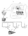
- FIG. 1 is a diagram showing an example of a mobile system.
- FIG. 2 shows an example of a mobile system.
- FIG. 3 is a diagram showing an example of an industrial plant.
- FIG. 4 is a diagram showing an example of a functional configuration of the wireless reception device.
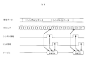
- FIG. 5 is a timing chart showing an example of processing operation of the wireless receiving apparatus.
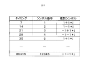
- FIG. 6 is a table showing an example of processing operation of the wireless receiving apparatus.
- FIG. 7 is a diagram showing an example of a functional configuration of the wireless reception device.
- FIG. 8 is a timing chart showing an example of processing operation of the wireless reception device.
- FIG. 9 is a table showing an example of processing operation of the wireless reception device.
- FIG. 10 is a diagram showing an example of an appearance configuration of a wireless receiving apparatus.
- FIG. 10 is a diagram showing an example of an appearance configuration of a wireless receiving apparatus.
- FIG. 11 is a diagram showing an example of a functional configuration of the wireless reception device.
- FIG. 12 is a timing chart showing an example of processing operation of the wireless reception device.
- FIG. 13 is a table showing an example of processing operation of the wireless reception device.
- FIG. 14 is a diagram showing an example of an appearance configuration of a wireless reception apparatus.
- each configuration, function, processing unit, processing means, and the like in the following embodiments may realize part or all of them as, for example, integrated circuits or other hardware.
- each configuration, function, processing unit, processing means, and the like described later may be realized by a program executed on a computer, that is, software. Programs, tables, files, and other information for realizing each configuration, function, processing unit, processing means, etc., memory, hard disk, storage device such as SSD (Solid State Drive), IC card, SD card, storage medium such as DVD, etc. Can be stored in
- FIG. 1 shows an example of the overall configuration of the first embodiment in which the wireless communication apparatus of the present invention is applied to a mobile system.
- the mobile system includes a communication analysis server 101, a communication analysis result 102 displayed on a display or the like, a terrestrial radio station 103, terrestrial radio relay stations 104 and 105, and dump trucks 106 and 107.
- the dump trucks 106 and 107 are equipped with onboard radio stations.
- the communication analysis server 101 and the terrestrial radio station 103 are connected by a communication cable.
- the terrestrial radio station 103 and the terrestrial radio relay stations 104 and 105 perform radio communications, and the terrestrial radio station 103 and the terrestrial radio relay stations 104 and 105 perform radio communications with the dump trucks 106 and 107.
- the dump trucks 106 and 107 also communicate with each other by the on-board radio station.
- the radio communication apparatus in each radio communication in a mobile system between the ground radio station and the ground radio relay station, between the ground radio station and the on-board radio station, and between the on-board radio station and the on-board radio station
- the bit number at the time of decoding the demodulation data is displayed on the display of the communication analysis server 101 in association with the recording timing of the reception data.
- the recording timing is set based on the internal clock signal, and this recording timing is set.
- the received data is stored in the storage device.
- demodulation processing of received data is performed in synchronization with the recording timing, and symbol numbers are demodulated in the order of demodulation for symbols demodulated by the demodulation processing at each recording timing.
- a demodulation symbol which is added and specifies this symbol is output, and a table in which the symbol number is associated with the demodulation symbol is created for each reception timing.
- Communication analysis is performed based on this table, and as shown at 102 in FIG. 1, for example, the result of communication analysis is displayed on the display of the communication analysis server 101.
- the correspondence between the highlighted bit of the demodulated data (in this example, “ABC4” of the demodulation bit string) and the received data at this recording timing is visual. Is displayed on.
- the demodulated data representing the communication result and the received data representing the communication state can be associated with each recording timing determined by the internal clock signal, for example, the level of the received data corresponding to a specific demodulated bit string is significantly reduced. If this is the case, it can be determined at this recording timing that the reception condition is extremely deteriorated.
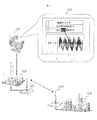
- FIG. 2 shows an example of the overall configuration of a mobile unit system according to a second embodiment in which the wireless communication apparatus of the present invention is applied to a railway vehicle operation control system.
- the operation control system includes a communication analysis server 201, a communication analysis result 202, a relay device 203, ground radio stations 204, 205, and 206, and a railway train 207.
- the communication analysis server 201 and the relay device 203 are connected by a communication cable.
- the terrestrial radio stations 204, 205, and 206 perform radio communication with the on-board radio stations mounted on the railway train 207.
- the same processing as in Embodiment 1 is performed to thereby obtain demodulated data representing the communication result and received data representing the communication state Can be associated with each recording timing determined by the internal clock signal.
- the wireless communication state in the operation control system can be analyzed.
- the communication state before and after that is analyzed based on the recording timing to identify the cause of the wireless communication failure. be able to.
- FIG. 3 shows an example of the overall configuration of an industrial plant according to this embodiment.
- the industrial plant comprises a communication analysis server 301, communication analysis results 302, plants 303 and 306, and terrestrial radio stations 304 and 305.
- the communication analysis server 301 and the plant 303 are connected by a communication cable.
- the terrestrial radio stations 304 and 305 communicate with each other wirelessly.
- the industrial plant according to the present embodiment performs the same processing as in the first embodiment in the radio communication between the terrestrial radio station and the terrestrial radio station, thereby recording timing as shown in the communication analysis result 302 as an example of display. , The correspondence between the highlighted bits of the demodulated data and the received data at this recording timing is visually displayed. As described above, by visually displaying the highlight data corresponding to a part of the demodulated data and the timing of the corresponding received data, the demodulated data representing the communication result and the received data representing the communication state are displayed. It can correspond. In particular, in an industrial plant, since there are many metal structures that interfere with wireless propagation, the wireless propagation environment is locally degraded. Therefore, it is important to always check the communication state according to the present invention. It is.
- FIG. 4 shows an example of a more detailed functional configuration of the wireless communication apparatus used for the systems of the first to third embodiments.
- the wireless communication apparatus shown in FIG. 4 includes an antenna 401, an RF unit 402, an ADC unit 403, a reception processing unit 404, and a signal recording unit 405.
- the signal recording unit 405 includes a memory 406 and a table 407.
- Received data received by the antenna 401 is down-converted by the RF unit 402, subjected to digital sampling processing by the ADC unit 403, and converted into digitalized received data 408.
- the reception processing unit 404 demodulates the reception data 408 and outputs a symbol number 409 and a demodulation symbol 410.
- the symbol number 409 is a serial number given in the order of demodulation for each of the demodulated symbols
- the demodulation symbol 410 is information obtained by the demodulation processing in order to specify the demodulated symbols. It is.
- the symbol number 409 and the demodulation symbol 410 are output at the timing when one symbol is demodulated.
- QPSK quadrature phase shift keying
- one symbol is configured to assign two bits and four states to a phase of every .pi. / 4, and two bits and four states that are reception data for one symbol are demodulated.
- the symbol number is counted up, and the demodulation bit string obtained by the demodulation processing is allocated to every 4 symbol numbers to be a demodulation symbol.
- the received data 408 is also input to the signal recording unit 405 and recorded in the memory 406. At this time, each time the received data 408 is recorded in the memory 406 one sample at a time, the recording timing is output to the table 407.
- the table 407 stores the recording timing value at that time when the symbol number 409 and the demodulation symbol 410 are input, and stores the symbol number 409 and the demodulation symbol 410 for each recording timing value.
- a table 407 in which the symbol numbers 409 of the demodulated data are associated with the demodulated symbols 410 is created for each recording timing value, and the received data 408 before reception processing is associated with the demodulated data after reception processing. be able to.
- FIG. 6 shows an example of the table, in which three items of the timing value, the symbol number 409 and the demodulation symbol 410 are collected in one row and are recorded in association with each other. For example, it is possible to associate that the symbol number 409 is 1 and the demodulation symbol 410 is 1 + 1 * j at the recording timing of the received data timing of 7.
- the device configuration according to the fourth embodiment it is possible to provide a wireless communication device which is highly convenient for a plurality of systems having different purposes of analyzing the state of wireless communication.
- FIG. 7 shows a wireless communication apparatus of the fifth embodiment.
- the wireless communication apparatus includes an antenna 701, an RF unit 702, an ADC unit 703, an AGC unit 704, a synchronization unit 705, a demodulation unit 706, a decoding unit 707, a reception buffer unit 708, a signal recording unit 709, a table creation unit 710, and signal storage.
- a section 711 is included.
- Received data received by the antenna 701 is down-converted by the RF unit 702, and digitally sampled by the ADC unit 703 to become received data 712 converted into digital data.
- the AGC unit 704 adjusts the level of the received data 712.
- the synchronization unit 705 performs frequency synchronization and timing synchronization of the received data 712.
- the demodulation unit 706 performs demodulation processing, and outputs symbol information 713 including a symbol number and a demodulation symbol.
- the symbol number is a sequential number given in the order of demodulation for each of the demodulated symbols, and the demodulation symbol is information obtained by the demodulation process. Symbol information 713 including these is output each time one symbol is demodulated.
- the decoding unit 707 performs a decoding process, and outputs the bit number 714 to the table creation unit 710 and the decoded bit 715 to the reception buffer unit 708, respectively.
- the bit number 714 is a number assigned to the plurality of decoded bits in the decoded order, and the decoded bit 715 is information obtained by the decoding process.
- the bit number 714 and the decoded bit 715 are output at the timing when one bit is decoded.
- the reception buffer unit 708 stores the decoded bit 715.
- the received data 712 is also input to the signal recording unit 709 and recorded in the memory 716.
- the memory address controller 717 is provided, and the memory address is cyclically designated by cyclically specifying the memory address.
- the memory address controller 717 outputs the recording timing to the table generation unit 710 each time the received data 712 is recorded in the memory 716 one sample at a time.
- the table generation unit 710 stores the recording timing value at that time, associates these and stores them.
- FIG. 9 shows an example of the table.
- Six items of symbol timing, symbol number, demodulation symbol, bit timing, bit number, and decoded bit are grouped into one line and associated and recorded. For example, when the symbol timing of received data is 7, it corresponds that the symbol number is 1, the demodulation symbol is 1 + 1 * j, the bit timing is 12, the bit number is 1, and the decoded bit is 0. be able to.
- FIG. 10 illustrates a configuration example according to the present embodiment, which includes a wireless communication apparatus 1001 and a result display unit 1002.
- the result display unit 1002 displays the bit string 1003 and the received data 1104, and visually indicates that the bit of the highlighted part in the bit string 1003 is associated with a specific part of the received data 1004. it's shown.
- This display result can be created based on the table information of FIG.
- FIG. 11 shows a wireless communication apparatus of the sixth embodiment.
- the wireless communication apparatus illustrated in FIG. 11 includes an antenna 1101, an RF unit 1102, an ADC unit 1103, an AGC unit 1104, a synchronization unit 1105, a demodulation unit 1106, a decoding unit 1107, an error determination unit 1108, a signal recording unit 1109, and a table creation unit 1110. , And a signal storage unit 1111.
- Received data received by the antenna 1101 is down-converted by the RF unit 1102, digitally sampled by the ADC unit 1103, and converted into digitalized received data 1112.
- the AGC unit 1104 adjusts the level of the received data 1112.
- the synchronization unit 1105 performs frequency synchronization and timing synchronization of the received data 1112.
- the demodulation unit 1106 performs demodulation processing and outputs symbol information 1113 including a symbol number and a demodulation symbol.
- the symbol number is a number given in the order in which the plurality of demodulated symbols are demodulated.
- the demodulation symbol is information obtained by demodulation processing. Symbol information 1113 including these is output at the timing when one symbol is demodulated.
- the decoding unit 1107 performs a decoding process and outputs bit information 1115 including a bit number and a decoded bit.
- the bit number is a number given in the decoded order to the plurality of decoded bits.
- the decoded bits are information obtained by the decoding process. Bit information 1115 including these is output at the timing when one bit is decoded.
- the error determination unit 1108 determines the presence or absence of a bit error of the decoded bit, and outputs the result.
- the received data 1112 is also input to the signal recording unit 1109.
- the input received data 1112 is recorded in the memory 1116.
- the memory address controller 1117 cyclically specifies the memory address to overwrite and record. Also, each time the received data 1112 is recorded in the memory 1116 one sample at a time, the memory address controller 1117 outputs the recording timing to the table generation unit 1110.
- the table creation unit 1110 receives symbol information 1113 including a symbol number and a demodulated symbol, bit information 1115 including a bit number and a decoded bit, and further receives a notification of a bit error from the error determination unit 1108, and records it. Save the timing values, associate them with each other, and save. This series of operations creates a table in which received data before reception processing, demodulation data after reception processing, reception timing of reception data, and bit number of demodulation data are associated only when bit error determination is made. can do.
- FIG. 13 shows an example of the table.
- symbol timing Six items of symbol timing, symbol number, demodulation symbol, bit timing, bit number, and decoded bit are grouped into one line and associated and recorded. For example, when the symbol timing of received data is 7, it corresponds that the symbol number is 1, the demodulation symbol is 1 + 1 * j, the bit timing is 12, the bit number is 1, and the decoded bit is 0. be able to.
- FIG. 14 shows a configuration example according to the present embodiment, which includes a wireless communication apparatus 1401 and a result display unit 1402.
- the result display unit 1402 displays the bit string 1403 and the received data 1404, and visually indicates that the location of the error bit in the bit string 1403 is highlighted and is associated with a specific location of the received data 1404. It is displayed on.
- This display result can be created based on the table information of FIG.
- the device configuration according to the sixth embodiment it is possible to provide a wireless communication device that is highly convenient for a plurality of systems having different purposes of analyzing the state of wireless communication.
Landscapes
- Engineering & Computer Science (AREA)
- Computer Networks & Wireless Communication (AREA)
- Signal Processing (AREA)
- Mobile Radio Communication Systems (AREA)
- Monitoring And Testing Of Transmission In General (AREA)
Abstract
無線通信装置において受信処理前の受信データと、受信処理後の復調データとを、受信データの受信タイミングに対応付けて記録することにより、無線信号の受信状況を受信タイミングレベルで高精度に解析する。 信号記録部(405)は、ADC部(403)からの受信データ(408)を記録タイミング毎にメモリ(406)に記憶する一方、この受信データ(408)を復調処理する受信処理部(404)から、記録タイミングに同期して、受信処理部(404)により復調処理された復調データに付与されるシンボル番号(409)と、復調シンボル(410)とを入力する。信号記録部(405)は、記録タイミングに対応させて、シンボル番号(409)と復調シンボル(410)を保存するテーブル(407)を作成し、受信処理前の受信データ(408)と受信処理部(404)による受信処理後の復調データとを、受信データの受信タイミングに対応付けて記録する。
Description
本発明は、無線通信装置、特に産業プラント及び移動体システム等に好適な無線通信装置に関する。
産業プラントや移動体システムに利用される無線通信装置においては、様々な外的要因によって、無線信号の受信状況が変化するため、これを解析し、通信障害の要因を詳細に分析したり、安定した通信が行われるよう、効果的な対策を採る必要がある。
無線信号の受信状況を解析するための技術を記載した文献として、下記の特許文献1~特許文献4がある。
無線信号の受信状況を解析するための技術を記載した文献として、下記の特許文献1~特許文献4がある。
特許文献1に記載の無線通信装置は、無線区間の検査装置、無線区間と有線区間の検査結果を解析して表示する検査システムに関するもので、無線区間の検査装置、無線区間と有線区間の検査結果を解析して表示する検査システムに関する技術が開示され、I/F部110は、ユーザから指示された検査対象の通信端末装置を示す端末ID情報、解析/表示装置400から出力された無線パラメータを示す情報(無線パラメータ情報)が入力され、無線パラメータ情報は、各無線パラメータを時刻情報と対応付けてリスト化する技術が開示されている。
特許文献2に記載の無線通信装置は、無線通信を行う無線データ通信システムにおいて、特に機器設置後の電波環境の監視を行う技術に関するもので、受信アンテナ11を通して受信した無線信号は復調手段12で受信データに復調され、受信した時間と受信データの内容とを後に解析できるように、受信側時計手段14で計測された時刻と受信データとを受信側記録手段15に記録することが開示されている。
特許文献3に記載の無線通信装置は、無線受信装置の測定データを容易に取得し、その受信特性を評価する受信特性評価システムに関する技術に関するもので、測定データは、復号されたテスト項目識別符号とこれら日時情報、バージョン情報とに関連付けられ、メンテナンス・ツール20に送られて、この測定データ記憶部21に同じ測定データが、テスト項目識別符号、日時情報及びバージョン情報とともに、保存されることが示されている。
特許文献4に記載の無線通信装置は、無線局間の無線通信を中継する無線通信システムにおける中継局装置及び無線通信方法に関するもので、無線局から受信した情報を記憶する記憶部12を備え、記憶部12は情報を記憶する際、その情報の種別、及び無線局から送信された情報を区別する送信元情報を、情報と関連付けて記憶する技術が開示されている。
これらの先行技術においては、通信結果や電波環境を、復調された受信データに基づいて評価することを基本としており、受信側で実際に受信した復調前のデータと、これを復調することにより得られる復調データの内容とを関連付けて解析していない。
このため、復調データにより得られる受信タイミングに基づいて、受信した無線信号の受信状況、通信障害の要因を高精度に解析することができず、通信品質を低下させる要因を正確に分析ができないという問題がある。
このため、復調データにより得られる受信タイミングに基づいて、受信した無線信号の受信状況、通信障害の要因を高精度に解析することができず、通信品質を低下させる要因を正確に分析ができないという問題がある。
そこで、本発明の目的は、無線信号を受信して受信処理を行う無線受信装置において、受信処理前の受信データと受信処理後の復調データとを、受信データの受信タイミングに対応付けたテーブルに記録することにより、受信した無線信号の受信状況や通信障害の要因を高精度に解析することにある。
上記課題を解決するために、例えば特許請求の範囲に記載の構成を採用する。
本願は上記課題を解決する手段を複数含んでいるが、その一例を挙げるならば、受信データを記録タイミング毎に記憶するとともに、この受信データを復調処理する受信処理部から、記録タイミングに同期して、復調処理された復調データに付与されたシンボル番号と、該復調データを特定する復調シンボルとを入力し、記録タイミングに対応させて前記シンボル番号と復調シンボルを保存するテーブルを作成する信号記録部を備えるようにした。
本願は上記課題を解決する手段を複数含んでいるが、その一例を挙げるならば、受信データを記録タイミング毎に記憶するとともに、この受信データを復調処理する受信処理部から、記録タイミングに同期して、復調処理された復調データに付与されたシンボル番号と、該復調データを特定する復調シンボルとを入力し、記録タイミングに対応させて前記シンボル番号と復調シンボルを保存するテーブルを作成する信号記録部を備えるようにした。
本発明によれば、受信処理前の受信データと、受信処理後の復調データと、前記受信データの受信タイミングと前記復調データのビット番号とを対応付けたテーブルとを記録部に記録でき、無線信号の受信状況を受信タイミングレベルで高精度に解析することができる。上記した以外の課題、構成及び効果は、以下の実施例の説明により明らかにされる。
以下の実施の形態においては、便宜上その必要があるときは、複数のセクションまたは実施の形態に分割して説明する。また、各実施の形態において、要素の数等(個数、数値、量、範囲等を含む)に言及する場合、特に明示した場合及び原理的に明らかに特定の数に限定される場合等を除き、その特定の数に限定されるものではなく、特定の数以上でも以下でもよい。なお、以下の実施の形態において、その構成要素(処理ステップ等も含む)は、特に明示した場合及び原理的に明らかに必須であると考えられる場合等を除き、必ずしも必須ではない。
また、以下の実施の形態における各構成、機能、処理部、処理手段等は、それらの一部又は全部を、例えば集積回路その他のハードウェアとして実現してもよい。
また、後述する各構成、機能、処理部、処理手段等は、コンピュータ上で実行されるプログラム、すなわち、ソフトウェアにより実現してもよい。各構成、機能、処理部、処理手段等を実現するプログラム、テーブル、ファイル等の情報は、メモリやハードディスク、SSD(Solid State Drive)等の記憶装置、ICカード、SDカード、DVD等の記憶媒体に格納することができる。
また、後述する各構成、機能、処理部、処理手段等は、コンピュータ上で実行されるプログラム、すなわち、ソフトウェアにより実現してもよい。各構成、機能、処理部、処理手段等を実現するプログラム、テーブル、ファイル等の情報は、メモリやハードディスク、SSD(Solid State Drive)等の記憶装置、ICカード、SDカード、DVD等の記憶媒体に格納することができる。
以下、本発明の実施の形態を図面に基づいて詳細に説明する。なお、実施の形態を説明するための全図において、同一の機能を有する部材には同一または関連する符号を付し、その繰り返しの説明は省略する。また、以下の実施の形態では、特に必要なとき以外は同一または同様な部分の説明を原則として繰り返さない。
[実施例1]
[システム構成]
図1に、本発明の無線通信装置を移動体システムに適用した、実施例1の全体構成例を示す。
この移動体システムは、通信解析サーバ101、ディプレイ等に表示される通信解析結果102、地上無線局103、地上無線中継局104及び105、ダンプトラック106及び107から構成される。ダンプトラック106及び107は車上無線局を搭載している。通信解析サーバ101と地上無線局103は、通信ケーブルで接続されている。地上無線局103と、地上無線中継局104及び105は、無線通信を行い、また、地上無線局103、地上無線中継局104及び105は、ダンプトラック106及び107と無線通信を行う。なお、ダンプトラック106及び107同士でも、車上無線局どおしで無線通信を行う。
[システム構成]
図1に、本発明の無線通信装置を移動体システムに適用した、実施例1の全体構成例を示す。
この移動体システムは、通信解析サーバ101、ディプレイ等に表示される通信解析結果102、地上無線局103、地上無線中継局104及び105、ダンプトラック106及び107から構成される。ダンプトラック106及び107は車上無線局を搭載している。通信解析サーバ101と地上無線局103は、通信ケーブルで接続されている。地上無線局103と、地上無線中継局104及び105は、無線通信を行い、また、地上無線局103、地上無線中継局104及び105は、ダンプトラック106及び107と無線通信を行う。なお、ダンプトラック106及び107同士でも、車上無線局どおしで無線通信を行う。
[処理動作・効果]
本実施例に係る無線通信装置では、地上無線局―地上無線中継局間、地上無線局―車上無線局間、車上無線局―車上無線局間の移動体システムにおける各無線通信において、受信処理前の受信データと受信処理後の復調データ、これに加えて、復調データを復号した際のビット番号を、受信データの記録タイミングとを対応付けて、通信解析サーバ101のディスプレイに表示させる。
すなわち、例えば、地上無線局103においては、通信解析サーバ101が地上無線中継局104を経由して受信データを受信した際、内部のクロック信号に基づいて、記録タイミングを設定して、この記録タイミング毎に、受信データを記憶装置に格納する。
一方、地上無線局103の受信処理部においては、記録タイミングに同期して受信データの復調処理がなされ、記録タイミング毎に、復調処理により復調されたシンボルに対して、復調された順にシンボル番号を付加し、このシンボルを特定する復調シンボルが出力され、受信タイミング毎に、このシンボル番号と復調シンボルとが対応付けられたデーブルが作成される。
本実施例に係る無線通信装置では、地上無線局―地上無線中継局間、地上無線局―車上無線局間、車上無線局―車上無線局間の移動体システムにおける各無線通信において、受信処理前の受信データと受信処理後の復調データ、これに加えて、復調データを復号した際のビット番号を、受信データの記録タイミングとを対応付けて、通信解析サーバ101のディスプレイに表示させる。
すなわち、例えば、地上無線局103においては、通信解析サーバ101が地上無線中継局104を経由して受信データを受信した際、内部のクロック信号に基づいて、記録タイミングを設定して、この記録タイミング毎に、受信データを記憶装置に格納する。
一方、地上無線局103の受信処理部においては、記録タイミングに同期して受信データの復調処理がなされ、記録タイミング毎に、復調処理により復調されたシンボルに対して、復調された順にシンボル番号を付加し、このシンボルを特定する復調シンボルが出力され、受信タイミング毎に、このシンボル番号と復調シンボルとが対応付けられたデーブルが作成される。
このテーブルに基づいて通信解析が行われ、例えば、図1の102に示すように、通信解析サーバ101のディスプレイに通信解析結果が表示される。
この例のように、記録タイミングに基づいて、復調データの一部のハイライトされたビット(この例では、復調ビット列の「ABC4」)と、この記録タイミングにおける受信データとの対応関係が視覚的に表示される。
これにより、通信結果を表す復調データと、通信状態を表す受信データを、内部のクロック信号により定まる記録タイミング毎に対応付けることができ、例えば、特定の復調ビット列に対応する受信データのレベルが著しく低下している場合には、この記録タイミングにおいて、受信状態が極端に悪化していることを判別することができる。
この例のように、記録タイミングに基づいて、復調データの一部のハイライトされたビット(この例では、復調ビット列の「ABC4」)と、この記録タイミングにおける受信データとの対応関係が視覚的に表示される。
これにより、通信結果を表す復調データと、通信状態を表す受信データを、内部のクロック信号により定まる記録タイミング毎に対応付けることができ、例えば、特定の復調ビット列に対応する受信データのレベルが著しく低下している場合には、この記録タイミングにおいて、受信状態が極端に悪化していることを判別することができる。
こうした解析結果により、例えば、特定の記録タイミングにおけるダンプトラック106の位置では、地上無線中継局104との間に、通信を阻害する障害物があることなどが判明し、地上無線中継局104を再配置したり、新たな地上無線中継局を追加するなどにより、ダンプトラック106、107の移動範囲全域にわたり、安定した通信を確保することが可能になる。特にこうした移動体システムにおいては、工事の進行等に応じて地上無線中継局の設置個所が頻繁に変更されるため、上述のように、通信状態の変動をモニターできることが安定した通信を維持管理する上できわめて有効である。
[実施例2]
[システム構成]
図2に、本発明の無線通信装置を鉄道車両の運行制御システムに適用した実施例2の移動体システムの全体構成例を示す。
この運行制御システムは、通信解析サーバ201、通信解析結果202、中継装置203、地上無線局204及び205及び206、鉄道列車207から構成される。通信解析サーバ201と中継装置203は、通信ケーブルで接続されている。地上無線局204及び205及び206は、鉄道列車207に搭載された車上無線局と無線通信を行う。
[システム構成]
図2に、本発明の無線通信装置を鉄道車両の運行制御システムに適用した実施例2の移動体システムの全体構成例を示す。
この運行制御システムは、通信解析サーバ201、通信解析結果202、中継装置203、地上無線局204及び205及び206、鉄道列車207から構成される。通信解析サーバ201と中継装置203は、通信ケーブルで接続されている。地上無線局204及び205及び206は、鉄道列車207に搭載された車上無線局と無線通信を行う。
[処理動作・効果]
本実施例に係る無線通信装置では、地上無線局―車上無線局間の無線通信において、実施例1と同様の処理を行うことで、通信結果を表す復調データと、通信状態を表す受信データを、内部のクロック信号により定まる記録タイミング毎に対応付けることができる。この通信解析結果202を、図2に示すように、通信解析サーバ201のディスプレイ等に表示することにより、運行制御システムにおける無線通信状態を解析することができる。特に、鉄道車両の運行制御システムにおいては、事故発生時の原因究明が重要であり、本実施例によって、その前後における通信状態を記録タイミングを基準にして解析し、無線通信の障害要因を特定することができる。
本実施例に係る無線通信装置では、地上無線局―車上無線局間の無線通信において、実施例1と同様の処理を行うことで、通信結果を表す復調データと、通信状態を表す受信データを、内部のクロック信号により定まる記録タイミング毎に対応付けることができる。この通信解析結果202を、図2に示すように、通信解析サーバ201のディスプレイ等に表示することにより、運行制御システムにおける無線通信状態を解析することができる。特に、鉄道車両の運行制御システムにおいては、事故発生時の原因究明が重要であり、本実施例によって、その前後における通信状態を記録タイミングを基準にして解析し、無線通信の障害要因を特定することができる。
[実施例3]
[システム構成]
図3に、本形態例に係る産業プラントの全体構成例を示す。本産業プラントは、通信解析サーバ301、通信解析結果302、プラント303及び306、地上無線局304及び305から構成される。通信解析サーバ301とプラント303は、通信ケーブルで接続されている。地上無線局304及び305は、互いに無線通信を行う。
[システム構成]
図3に、本形態例に係る産業プラントの全体構成例を示す。本産業プラントは、通信解析サーバ301、通信解析結果302、プラント303及び306、地上無線局304及び305から構成される。通信解析サーバ301とプラント303は、通信ケーブルで接続されている。地上無線局304及び305は、互いに無線通信を行う。
[処理動作・効果]
本形態例に係る産業プラントは、地上無線局―地上無線局間の無線通信において、実施例1と同様の処理を行うことにより、表示の一例として、通信解析結果302に示すように、記録タイミングに基づいて、復調データの一部のハイライトされたビットと、この記録タイミングにおける受信データとの対応関係が視覚的に表示される。
このように、復調データの一部のハイライトされたビットと対応する受信データのタイミングを対応付けて、視覚的に表示することにより、通信結果を表す復調データと、通信状態を表す受信データを対応付けることができる。
特に、産業プラントにおいては、無線伝搬の障害となる金属製の構造物が多い環境であることから、局所的に無線伝搬環境が劣悪になるため、本発明によって通信状態を常時確認することが重要である。
本形態例に係る産業プラントは、地上無線局―地上無線局間の無線通信において、実施例1と同様の処理を行うことにより、表示の一例として、通信解析結果302に示すように、記録タイミングに基づいて、復調データの一部のハイライトされたビットと、この記録タイミングにおける受信データとの対応関係が視覚的に表示される。
このように、復調データの一部のハイライトされたビットと対応する受信データのタイミングを対応付けて、視覚的に表示することにより、通信結果を表す復調データと、通信状態を表す受信データを対応付けることができる。
特に、産業プラントにおいては、無線伝搬の障害となる金属製の構造物が多い環境であることから、局所的に無線伝搬環境が劣悪になるため、本発明によって通信状態を常時確認することが重要である。
[実施例4]
[装置構成]
図4に、実施例1~3のシステムに利用される無線通信装置のより詳細な機能構成の例を示す。図4に示す無線通信装置は、アンテナ401、RF部402、ADC部403、受信処理部404、信号記録部405から構成され、信号記録部405は、メモリ406、テーブル407から構成される。
アンテナ401で受信した受信データは、RF部402でダウンコンバージョンされ、ADC部403によるデジタルサンプリング処理を経て、デジタルデータ化された受信データ408となる。受信処理部404は、この受信データ408に対して復調処理を行い、シンボル番号409と復調シンボル410を出力する。
[装置構成]
図4に、実施例1~3のシステムに利用される無線通信装置のより詳細な機能構成の例を示す。図4に示す無線通信装置は、アンテナ401、RF部402、ADC部403、受信処理部404、信号記録部405から構成され、信号記録部405は、メモリ406、テーブル407から構成される。
アンテナ401で受信した受信データは、RF部402でダウンコンバージョンされ、ADC部403によるデジタルサンプリング処理を経て、デジタルデータ化された受信データ408となる。受信処理部404は、この受信データ408に対して復調処理を行い、シンボル番号409と復調シンボル410を出力する。
ここで、シンボル番号409とは、復調されたシンボル毎に、復調された順番で付けられた連続番号であり、復調シンボル410は、復調されたシンボルを特定するため、復調処理によって得られた情報である。
シンボル番号409及び復調シンボル410は、1つのシンボルが復調されたタイミングで出力される。例えば、QPSK(直交位相シフトキーイング)の場合、1シンボルで2ビット4状態をπ/4毎の位相に割り当てる構成となっており、1シンボル分の受信データである2ビット4状態が復調される度に、シンボル番号がカウントアップされ、復調処理によって得られた復調ビット列を、4シンボル番号毎に割り振って復調シンボルとしている。
シンボル番号409及び復調シンボル410は、1つのシンボルが復調されたタイミングで出力される。例えば、QPSK(直交位相シフトキーイング)の場合、1シンボルで2ビット4状態をπ/4毎の位相に割り当てる構成となっており、1シンボル分の受信データである2ビット4状態が復調される度に、シンボル番号がカウントアップされ、復調処理によって得られた復調ビット列を、4シンボル番号毎に割り振って復調シンボルとしている。
受信データ408は、信号記録部405へも入力され、メモリ406に記録される。このとき、受信データ408が1サンプルずつメモリ406に記録されるたびに、その記録タイミングをテーブル407へ出力する。
テーブル407は、シンボル番号409及び復調シンボル410が入力されたときに、その時点の記録タイミング値を保存し、記録タイミング値毎にシンボル番号409と復調シンボル410を保存する。
この一連の動作により各記録タイミング値毎に、復調データのシンボル番号409と復調シンボル410とを対応付けたテーブル407が作成され、受信処理前の受信データ408と受信処理後の復調データとを対応付けることができる。
テーブル407は、シンボル番号409及び復調シンボル410が入力されたときに、その時点の記録タイミング値を保存し、記録タイミング値毎にシンボル番号409と復調シンボル410を保存する。
この一連の動作により各記録タイミング値毎に、復調データのシンボル番号409と復調シンボル410とを対応付けたテーブル407が作成され、受信処理前の受信データ408と受信処理後の復調データとを対応付けることができる。
[処理動作・効果]
以上に説明した処理動作例の詳細を、図5に示す。受信データを記録し続ける間、クロック信号に同期したタイミング値はカウントアップされる。受信処理部404は受信データに対して復調処理を行い、1シンボルが復調された時点で、シンボル番号409と、復調シンボル410をテーブルへと追記する。
また、その時点でのタイミング値をテーブルへと追記する。図6は、テーブルの一例を示しており、タイミング値、シンボル番号409、復調シンボル410の3項目を1行にまとめ、対応付けて記録する。例えば、受信データのタイミングが7の記録タイミングにおいては、シンボル番号409が1で、復調シンボル410は1+1*jであったと対応付けることができる。以上のとおり、実施例4に係る装置構成によれば、無線通信の状態を解析する目的が異なる複数のシステムにとって利便性の高い無線通信装置を提供することができる。
以上に説明した処理動作例の詳細を、図5に示す。受信データを記録し続ける間、クロック信号に同期したタイミング値はカウントアップされる。受信処理部404は受信データに対して復調処理を行い、1シンボルが復調された時点で、シンボル番号409と、復調シンボル410をテーブルへと追記する。
また、その時点でのタイミング値をテーブルへと追記する。図6は、テーブルの一例を示しており、タイミング値、シンボル番号409、復調シンボル410の3項目を1行にまとめ、対応付けて記録する。例えば、受信データのタイミングが7の記録タイミングにおいては、シンボル番号409が1で、復調シンボル410は1+1*jであったと対応付けることができる。以上のとおり、実施例4に係る装置構成によれば、無線通信の状態を解析する目的が異なる複数のシステムにとって利便性の高い無線通信装置を提供することができる。
[実施例5]
[装置構成]
図7に実施例5の無線通信装置を示す。
この無線通信装置は、アンテナ701、RF部702、ADC部703、AGC部704、同期部705、復調部706、復号部707、受信バッファ部708、信号記録部709、テーブル作成部710、信号保存部711から構成される。
アンテナ701で受信した受信データは、RF部702でダウンコンバージョンされ、ADC部703でデジタルサンプリングされデジタルデータ化された受信データ712となる。AGC部704は、受信データ712のレベル調整を行う。同期部705は、受信データ712の周波数同期とタイミング同期を行う。
[装置構成]
図7に実施例5の無線通信装置を示す。
この無線通信装置は、アンテナ701、RF部702、ADC部703、AGC部704、同期部705、復調部706、復号部707、受信バッファ部708、信号記録部709、テーブル作成部710、信号保存部711から構成される。
アンテナ701で受信した受信データは、RF部702でダウンコンバージョンされ、ADC部703でデジタルサンプリングされデジタルデータ化された受信データ712となる。AGC部704は、受信データ712のレベル調整を行う。同期部705は、受信データ712の周波数同期とタイミング同期を行う。
復調部706は、復調処理を行い、シンボル番号と復調シンボルを含むシンボル情報713を出力する。シンボル番号とは、復調されたシンボル毎に、復調された順番で付けられた連続番号であり、復調シンボルは、復調処理によって得られた情報である。これらを含むシンボル情報713は、1つのシンボルが復調される度に出力される。
復号部707は、復号処理を行い、ビット番号714をテーブル作成部710に、復号ビット715を受信バッファ部708にそれぞれ出力する。ビット番号714とは、復号された複数のビットに、復号された順番で付けられた番号であり、復号ビット715は、復号処理によって得られた情報である。
復号部707は、復号処理を行い、ビット番号714をテーブル作成部710に、復号ビット715を受信バッファ部708にそれぞれ出力する。ビット番号714とは、復号された複数のビットに、復号された順番で付けられた番号であり、復号ビット715は、復号処理によって得られた情報である。
ビット番号714及び復号ビット715は、1つのビットが復号されたタイミングで出力される。受信バッファ部708は、復号ビット715を格納する。また、受信データ712は、信号記録部709へも入力され、メモリ716へ記録される。受信データ712がメモリ容量を超えて記録される場合、メモリアドレスコントローラ717を設け、メモリアドレスをサイクリックに指定することで上書き記録する。
またメモリアドレスコントローラ717は、受信データ712がメモリ716へ1サンプルずつ記録されるたびに、その記録タイミングをテーブル作成部710へ出力する。テーブル作成部710は、シンボル番号と復調シンボルを含むシンボル情報713、ビット番号714及び復号ビット715が入力されたときに、その際の記録タイミング値を保存し、これらを対応付けて保存する。
またメモリアドレスコントローラ717は、受信データ712がメモリ716へ1サンプルずつ記録されるたびに、その記録タイミングをテーブル作成部710へ出力する。テーブル作成部710は、シンボル番号と復調シンボルを含むシンボル情報713、ビット番号714及び復号ビット715が入力されたときに、その際の記録タイミング値を保存し、これらを対応付けて保存する。
この一連の動作により、記録タイミング毎に、受信データ712、シンボル番号と復調シンボルを含むシンボル情報713、そして、復号処理によって得られたビット番号714を対応付けたテーブルを作成することができる。
[処理動作・効果]
以上に説明した実施例5の処理動作例の詳細を図8に示す。
ADC部403でデジタルサンプリングされた受信データを記録し続ける間、クロック周波数に同期したタイミング値はカウントアップされる。1シンボルが復調された時点で、シンボル番号と復調シンボルを含むシンボル情報713に含まれるをテーブルへと追記する。また、1ビットが復号された時点で、ビット番号と、復号ビットをテーブルへと追記する。またその時点でのタイミング値をビットタイミングとしてテーブルへと追記する。
以上に説明した実施例5の処理動作例の詳細を図8に示す。
ADC部403でデジタルサンプリングされた受信データを記録し続ける間、クロック周波数に同期したタイミング値はカウントアップされる。1シンボルが復調された時点で、シンボル番号と復調シンボルを含むシンボル情報713に含まれるをテーブルへと追記する。また、1ビットが復号された時点で、ビット番号と、復号ビットをテーブルへと追記する。またその時点でのタイミング値をビットタイミングとしてテーブルへと追記する。
図9は、テーブルの一例を示している。シンボルタイミング、シンボル番号、復調シンボル、ビットタイミング、ビット番号、復号ビットの6項目を1行にまとめ、対応付けて記録する。例えば、受信データのシンボルタイミングが7の箇所においては、シンボル番号が1で、復調シンボルは1+1*jであり、ビットタイミングが12で、ビット番号が1、復号ビットが0であった、と対応付けることができる。
図10は、本実施例に係る構成例を示しており、無線通信装置1001と、結果表示部1002から構成される。結果表示部1002は、ビット列1003と受信データ1104を表示しており、ビット列1003内のハイライトされている箇所のビットが、受信データ1004のある特定の箇所と対応付けられることを、視覚的に表示している。この表示結果は、図9のテーブル情報を元にして作成することができる。以上のとおり、形態例5に係る装置構成によれば、無線通信の状態を解析する目的が異なる複数のシステムにとって利便性の高い無線通信装置を提供することができる。
[実施例6]
[装置構成]
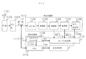
図11に、実施例6の無線通信装置を示す。図11に示す無線通信装置は、アンテナ1101、RF部1102、ADC部1103、AGC部1104、同期部1105、復調部1106、復号部1107、エラー判定部1108、信号記録部1109、テーブル作成部1110、信号保存部1111から構成される。
アンテナ1101で受信した受信データは、RF部1102でダウンコンバージョンされ、ADC部1103でデジタルサンプリングされ、デジタルデータ化された受信データ1112となる。AGC部1104は、受信データ1112のレベル調整を行う。同期部1105は、受信データ1112の周波数同期とタイミング同期を行う。
[装置構成]
図11に、実施例6の無線通信装置を示す。図11に示す無線通信装置は、アンテナ1101、RF部1102、ADC部1103、AGC部1104、同期部1105、復調部1106、復号部1107、エラー判定部1108、信号記録部1109、テーブル作成部1110、信号保存部1111から構成される。
アンテナ1101で受信した受信データは、RF部1102でダウンコンバージョンされ、ADC部1103でデジタルサンプリングされ、デジタルデータ化された受信データ1112となる。AGC部1104は、受信データ1112のレベル調整を行う。同期部1105は、受信データ1112の周波数同期とタイミング同期を行う。
復調部1106は、復調処理を行い、シンボル番号と復調シンボルを含むシンボル情報1113を出力する。シンボル番号とは、復調された複数のシンボルに、復調された順番で付けられた番号である。復調シンボルは、復調処理によって得られた情報である。これらを含むシンボル情報1113は、1つのシンボルが復調されたタイミングで出力される。復号部1107は、復号処理を行い、ビット番号と復号ビットを含むビット情報1115を出力する。
ビット番号とは、復号された複数のビットに、復号された順番で付けられた番号である。復号ビットは、復号処理によって得られた情報である。これらを含むビット情報1115は、1つのビットが復号されたタイミングで出力される。エラー判定部1108は、復号ビットのビットエラーの有無を判定し、結果を出力する。
ビット番号とは、復号された複数のビットに、復号された順番で付けられた番号である。復号ビットは、復号処理によって得られた情報である。これらを含むビット情報1115は、1つのビットが復号されたタイミングで出力される。エラー判定部1108は、復号ビットのビットエラーの有無を判定し、結果を出力する。
また受信データ1112は、信号記録部1109へも入力される。入力された受信データ1112は、メモリ1116へ記録される。受信データ1112がメモリ容量を超えて記録される場合は、メモリアドレスコントローラ1117がメモリアドレスをサイクリックに指定することで、上書き記録する。またメモリアドレスコントローラ1117は、受信データ1112がメモリ1116へ1サンプルずつ記録されるたびに、その記録タイミングをテーブル作成部1110へ出力する。テーブル作成部1110には、シンボル番号と復調シンボルを含むシンボル情報1113、ビット番号と復号ビットを含むビット情報1115が入力され、さらにエラー判定部1108からビットエラーの通知を受け取ったときに、その記録タイミング値を保存し、これらを対応付けて保存する。
この一連の動作により、ビットエラー判定だった場合にのみ、受信処理前の受信データ、受信処理後の復調データ、受信データの受信タイミング、そして、復調データのビット番号とを対応付けたテーブルを作成することができる。
この一連の動作により、ビットエラー判定だった場合にのみ、受信処理前の受信データ、受信処理後の復調データ、受信データの受信タイミング、そして、復調データのビット番号とを対応付けたテーブルを作成することができる。
[処理動作・効果]
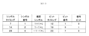
以上に説明した処理動作例の詳細を、図12に示す。受信データを記録し続ける間、タイミング値はカウントアップされる。1シンボルが復調された時点で、シンボル情報1113に含まれるシンボル番号と復調シンボルをテーブルへと追記する。また、1ビットが復号された時点で、ビット番号と、復号ビットをテーブルへと追記する。またその時点でのタイミング値をテーブルへと追記する。そして、復号ビットがエラー判定だったとき、追記したテーブル情報を保存する。復号ビットが正常判定だった場合、追記したテーブル情報を破棄する。これにより、エラービットに関する情報のみを、取捨選択して保存することがきる。図13は、テーブルの一例を示している。シンボルタイミング、シンボル番号、復調シンボル、ビットタイミング、ビット番号、復号ビットの6項目を1行にまとめ、対応付けて記録する。例えば、受信データのシンボルタイミングが7の箇所においては、シンボル番号が1で、復調シンボルは1+1*jであり、ビットタイミングが12で、ビット番号が1、復号ビットが0であった、と対応付けることができる。
以上に説明した処理動作例の詳細を、図12に示す。受信データを記録し続ける間、タイミング値はカウントアップされる。1シンボルが復調された時点で、シンボル情報1113に含まれるシンボル番号と復調シンボルをテーブルへと追記する。また、1ビットが復号された時点で、ビット番号と、復号ビットをテーブルへと追記する。またその時点でのタイミング値をテーブルへと追記する。そして、復号ビットがエラー判定だったとき、追記したテーブル情報を保存する。復号ビットが正常判定だった場合、追記したテーブル情報を破棄する。これにより、エラービットに関する情報のみを、取捨選択して保存することがきる。図13は、テーブルの一例を示している。シンボルタイミング、シンボル番号、復調シンボル、ビットタイミング、ビット番号、復号ビットの6項目を1行にまとめ、対応付けて記録する。例えば、受信データのシンボルタイミングが7の箇所においては、シンボル番号が1で、復調シンボルは1+1*jであり、ビットタイミングが12で、ビット番号が1、復号ビットが0であった、と対応付けることができる。
図13に示すテーブルには、図12で示した処理動作の結果、エラービットに関する情報のみが保存される。これにより、膨大な受信データ情報の中から、通信エラーとなった原因に関する情報のみを取捨選択することができ、また記録容量を大幅に削減することができる。
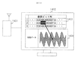
図14に、本形態例に係る構成例を示しており、無線通信装置1401と、結果表示部1402から構成される。結果表示部1402は、ビット列1403と受信データ1404を表示しており、ビット列1403内のエラービットの箇所がハイライトされており、受信データ1404のある特定の箇所と対応付けられることを、視覚的に表示している。この表示結果は、図13のテーブル情報を元にして作成することができる。
以上のとおり、実施例6に係る装置構成によれば、無線通信の状態を解析する目的が異なる複数のシステムにとって利便性の高い無線通信装置を提供することができる。
図14に、本形態例に係る構成例を示しており、無線通信装置1401と、結果表示部1402から構成される。結果表示部1402は、ビット列1403と受信データ1404を表示しており、ビット列1403内のエラービットの箇所がハイライトされており、受信データ1404のある特定の箇所と対応付けられることを、視覚的に表示している。この表示結果は、図13のテーブル情報を元にして作成することができる。
以上のとおり、実施例6に係る装置構成によれば、無線通信の状態を解析する目的が異なる複数のシステムにとって利便性の高い無線通信装置を提供することができる。
101 通信解析サーバ
102 通信解析結果
103 地上無線局
104、105 地上無線中継局
106、107 ダンプトラック
201 通信解析サーバ
202 通信解析結果
203 中継装置
204、205、206 地上無線局
207 鉄道列車
301 通信解析サーバ
302 通信解析結果
303、306 プラント
304、305 地上無線局
401 アンテナ
402 RF部
403 ADC部
404 受信処理部
405 信号記録部
406 メモリ
407 テーブル
408 受信データ
409 シンボル番号
410 復調シンボル
411 記録タイミング
701 アンテナ
702 RF部
703 ADC部
704 AGC部
705 同期部
706 復調部
707 復号部
708 受信バッファ部
709 信号記録部
710 テーブル作成部
711 信号保存部
712 受信データ
713 シンボル情報
714 ビット(番号)(情報)
715 復号ビット
716 メモリ
717 メモリアドレスコントローラ
1001 無線通信装置
1002 結果表示部
1003 ビット列
1004 受信データ
1101 アンテナ
1102 RF部
1103 ADC部
1104 AGC部
1105 同期部
1106 復調部
1107 復号部
1108 エラー判定部
1109 信号記録部
1110 テーブル作成部
1111 信号保存部
1112 受信データ
1113 シンボル情報
1115 ビット情報
1116 メモリ
1117 メモリアドレスコントローラ
1401 無線通信装置
1402 結果表示部
1403 ビット列
1404 受信データ
102 通信解析結果
103 地上無線局
104、105 地上無線中継局
106、107 ダンプトラック
201 通信解析サーバ
202 通信解析結果
203 中継装置
204、205、206 地上無線局
207 鉄道列車
301 通信解析サーバ
302 通信解析結果
303、306 プラント
304、305 地上無線局
401 アンテナ
402 RF部
403 ADC部
404 受信処理部
405 信号記録部
406 メモリ
407 テーブル
408 受信データ
409 シンボル番号
410 復調シンボル
411 記録タイミング
701 アンテナ
702 RF部
703 ADC部
704 AGC部
705 同期部
706 復調部
707 復号部
708 受信バッファ部
709 信号記録部
710 テーブル作成部
711 信号保存部
712 受信データ
713 シンボル情報
714 ビット(番号)(情報)
715 復号ビット
716 メモリ
717 メモリアドレスコントローラ
1001 無線通信装置
1002 結果表示部
1003 ビット列
1004 受信データ
1101 アンテナ
1102 RF部
1103 ADC部
1104 AGC部
1105 同期部
1106 復調部
1107 復号部
1108 エラー判定部
1109 信号記録部
1110 テーブル作成部
1111 信号保存部
1112 受信データ
1113 シンボル情報
1115 ビット情報
1116 メモリ
1117 メモリアドレスコントローラ
1401 無線通信装置
1402 結果表示部
1403 ビット列
1404 受信データ
Claims (9)
- 受信データを記録タイミング毎に記憶するとともに、前記受信データを復調処理する受信処理部から、前記記録タイミングに同期して、復調処理された復調データに付与されたシンボル番号と、該復調データを特定する復調シンボルとを入力し、前記記録タイミングに対応させて前記シンボル番号と前記復調シンボルを保存するテーブルを作成する信号記録部を備えたことを特徴する無線通信装置。
- 前記受信処理部が、前記受信データの1シンボル分を復調したタイミングで前記シンボル番号と前記復調シンボルを前記テーブルへ出力することを特徴とする請求項1に記載の無線通信装置。
- 前記シンボル番号は、前記受信データを復調した順に付加された番号であることを特徴とする請求項1に記載の無線通信装置。
- 前記受信処理部は、復調処理された復調データを複合する複合部を備え、前記受信処理前の受信データの1シンボル分を復調したタイミングで、前記復調シンボルを前記テーブルへ出力するとともに、前記復号部が1ビットを復号したタイミングで該復号ビットのビット番号を前記テーブルへ出力することを特徴とする請求項3に記載の無線通信装置。
- 前記ビット番号は、前記復号部が1ビットの復号を行う度に、復号した順に付与されたものであることを特徴とする請求項4に記載の無線通信装置。
- 前記信号記録部はメモリコントローラとメモリとを有し、前記メモリコントローラは、前記受信タイミングに応じて、前記メモリが前記受信データを記録するアドレスをサイクリックに指定するとともに、該受信タイミングを前記テーブルを作成するデーブル作成部へ出力することを特徴とする請求項4に記載の無線通信装置。
- 前記テーブルを作成するテーブル作成部は、前記復調部から前記シンボル番号と前記復調シンボルが入力された時点で、前記受信タイミングをシンボルタイミングとして記録するとともに、前記復号部から前記ビット番号と前記復号ビットが入力された時点で、前記受信タイミングをビットタイミングとして記録し、前記記録タイミングに対応させて、前記シンボルタイミングと前記ビットタイミングをテーブルへ保存することを特徴とする請求項4に記載の無線通信装置。
- 前記受信処理部はエラー判定部を有しており、前記シンボルタイミングと前記ビットタイミングが出力された時点で、前記エラー判定部が、前記復号ビットがエラーか正常かを判定し、この判定結果を前記テーブル作成部へ出力することを特徴とする請求項4に記載の無線通信装置。
- 前記テーブル作成部は、前記エラー判定結果がビットエラーだった場合のみ、前記シンボルタイミングと前記シンボル番号と前記復調シンボルと前記ビットタイミングと前記ビット番号と前記復号ビットを記録し、前記エラー判定結果が正常だった場合は、前記シンボルタイミングと前記シンボル番号と前記復調シンボルと前記ビットタイミングと前記ビット番号と前記復号ビットを破棄することを特徴とする請求項8に記載の無線通信装置。
Priority Applications (2)
| Application Number | Priority Date | Filing Date | Title |
|---|---|---|---|
| JP2014552811A JP5820937B2 (ja) | 2012-12-19 | 2012-12-19 | 無線通信装置 |
| PCT/JP2012/082906 WO2014097420A1 (ja) | 2012-12-19 | 2012-12-19 | 無線通信装置 |
Applications Claiming Priority (1)
| Application Number | Priority Date | Filing Date | Title |
|---|---|---|---|
| PCT/JP2012/082906 WO2014097420A1 (ja) | 2012-12-19 | 2012-12-19 | 無線通信装置 |
Publications (1)
| Publication Number | Publication Date |
|---|---|
| WO2014097420A1 true WO2014097420A1 (ja) | 2014-06-26 |
Family
ID=50977804
Family Applications (1)
| Application Number | Title | Priority Date | Filing Date |
|---|---|---|---|
| PCT/JP2012/082906 Ceased WO2014097420A1 (ja) | 2012-12-19 | 2012-12-19 | 無線通信装置 |
Country Status (2)
| Country | Link |
|---|---|
| JP (1) | JP5820937B2 (ja) |
| WO (1) | WO2014097420A1 (ja) |
Cited By (1)
| Publication number | Priority date | Publication date | Assignee | Title |
|---|---|---|---|---|
| CN106375045A (zh) * | 2016-09-08 | 2017-02-01 | 北京交通大学 | 一种高速铁路场景下多链路信道探测系统与方法 |
Citations (6)
| Publication number | Priority date | Publication date | Assignee | Title |
|---|---|---|---|---|
| JPH07336315A (ja) * | 1994-06-09 | 1995-12-22 | Fujitsu Ltd | 受信状態情報出力装置 |
| JP2000165317A (ja) * | 1998-11-27 | 2000-06-16 | Anritsu Corp | 移動端末試験装置における拡散コードの位相ずれ測定装置 |
| JP2007019741A (ja) * | 2005-07-06 | 2007-01-25 | Anritsu Corp | バースト信号解析装置 |
| JP2008288671A (ja) * | 2007-05-15 | 2008-11-27 | Hitachi Kokusai Electric Inc | 無線通信システム |
| JP2009130923A (ja) * | 2007-11-24 | 2009-06-11 | Takeshi Hoshiko | パケット通信システム |
| JP2011130086A (ja) * | 2009-12-16 | 2011-06-30 | Anritsu Corp | 移動体通信端末試験装置及び試験結果表示方法 |
-
2012
- 2012-12-19 WO PCT/JP2012/082906 patent/WO2014097420A1/ja not_active Ceased
- 2012-12-19 JP JP2014552811A patent/JP5820937B2/ja not_active Expired - Fee Related
Patent Citations (6)
| Publication number | Priority date | Publication date | Assignee | Title |
|---|---|---|---|---|
| JPH07336315A (ja) * | 1994-06-09 | 1995-12-22 | Fujitsu Ltd | 受信状態情報出力装置 |
| JP2000165317A (ja) * | 1998-11-27 | 2000-06-16 | Anritsu Corp | 移動端末試験装置における拡散コードの位相ずれ測定装置 |
| JP2007019741A (ja) * | 2005-07-06 | 2007-01-25 | Anritsu Corp | バースト信号解析装置 |
| JP2008288671A (ja) * | 2007-05-15 | 2008-11-27 | Hitachi Kokusai Electric Inc | 無線通信システム |
| JP2009130923A (ja) * | 2007-11-24 | 2009-06-11 | Takeshi Hoshiko | パケット通信システム |
| JP2011130086A (ja) * | 2009-12-16 | 2011-06-30 | Anritsu Corp | 移動体通信端末試験装置及び試験結果表示方法 |
Cited By (1)
| Publication number | Priority date | Publication date | Assignee | Title |
|---|---|---|---|---|
| CN106375045A (zh) * | 2016-09-08 | 2017-02-01 | 北京交通大学 | 一种高速铁路场景下多链路信道探测系统与方法 |
Also Published As
| Publication number | Publication date |
|---|---|
| JPWO2014097420A1 (ja) | 2017-01-12 |
| JP5820937B2 (ja) | 2015-11-24 |
Similar Documents
| Publication | Publication Date | Title |
|---|---|---|
| CN102412879B (zh) | 针对诊断和性能优化具有集成的基于位置的测量的无线通信系统 | |
| JP5026344B2 (ja) | 非破壊試験計器用gps対応型データロギング・システム | |
| US20130073605A1 (en) | Publication of Equipment Status | |
| US8594822B2 (en) | Electronic supervisor | |
| WO2007044986A3 (en) | System and method for remote monitoring in a wireless network | |
| CN203502040U (zh) | 车载多媒体终端的测试系统 | |
| US10700943B2 (en) | System and method for collection of radio environment information using a limited datalink | |
| Paquin et al. | New constraints on the P–T evolution of the Alpe Arami garnet peridotite body (Central Alps, Switzerland) | |
| CN109429252B (zh) | 通信状态分析方法和通信状态分析系统 | |
| CN103676659B (zh) | 一种具智能记录的诊断仪及其记录方法 | |
| JP5820937B2 (ja) | 無線通信装置 | |
| TW200745843A (en) | System and method for electronic diagnostics of a process vacuum environment | |
| WO2018110553A1 (ja) | 携帯動揺計、動揺測定プログラム | |
| CN113140109A (zh) | 一种路测数据处理方法、装置、计算机设备及存储介质 | |
| US9215047B2 (en) | Signal processing device and method by use of wireless communication | |
| US12032430B1 (en) | Condition-based maintenance techniques | |
| KR20130019348A (ko) | 무선 통신 장치 및 그것을 사용한 열차 제어 시스템 | |
| JP5208230B2 (ja) | 移動通信端末試験装置及びメッセージ表示方法 | |
| CN206450249U (zh) | 一种移动式在线设备状态监测装置 | |
| JP2010087948A (ja) | 監視装置 | |
| WO2009022056A8 (en) | Conversion system and method in multioperator environment | |
| Dolev | Introduction to the special section on prognostics and health management | |
| JP5924952B2 (ja) | 通信解析装置及び通信解析方法 | |
| Morgan et al. | PCM Backfill: Providing PCM to the Control Room Without Dropouts | |
| JP2012199778A (ja) | 通信システム |
Legal Events
| Date | Code | Title | Description |
|---|---|---|---|
| 121 | Ep: the epo has been informed by wipo that ep was designated in this application |
Ref document number: 12890333 Country of ref document: EP Kind code of ref document: A1 |
|
| ENP | Entry into the national phase |
Ref document number: 2014552811 Country of ref document: JP Kind code of ref document: A |
|
| NENP | Non-entry into the national phase |
Ref country code: DE |
|
| 122 | Ep: pct application non-entry in european phase |
Ref document number: 12890333 Country of ref document: EP Kind code of ref document: A1 |