WO2014092123A1 - チャック体及びシャープペンシル - Google Patents
チャック体及びシャープペンシル Download PDFInfo
- Publication number
- WO2014092123A1 WO2014092123A1 PCT/JP2013/083224 JP2013083224W WO2014092123A1 WO 2014092123 A1 WO2014092123 A1 WO 2014092123A1 JP 2013083224 W JP2013083224 W JP 2013083224W WO 2014092123 A1 WO2014092123 A1 WO 2014092123A1
- Authority
- WO
- WIPO (PCT)
- Prior art keywords
- chuck
- fastener
- core
- tapered
- chuck body
- Prior art date
- Legal status (The legal status is an assumption and is not a legal conclusion. Google has not performed a legal analysis and makes no representation as to the accuracy of the status listed.)
- Ceased
Links
Images








Classifications
-
- B—PERFORMING OPERATIONS; TRANSPORTING
- B43—WRITING OR DRAWING IMPLEMENTS; BUREAU ACCESSORIES
- B43K—IMPLEMENTS FOR WRITING OR DRAWING
- B43K21/00—Propelling pencils
- B43K21/02—Writing-core feeding mechanisms
- B43K21/16—Writing-core feeding mechanisms with stepwise feed of writing-cores
-
- B—PERFORMING OPERATIONS; TRANSPORTING
- B43—WRITING OR DRAWING IMPLEMENTS; BUREAU ACCESSORIES
- B43K—IMPLEMENTS FOR WRITING OR DRAWING
- B43K21/00—Propelling pencils
- B43K21/02—Writing-core feeding mechanisms
- B43K21/22—Writing-cores gripping means, e.g. chucks
Definitions
- the present invention relates to a chuck body for feeding and holding a mechanical pencil lead. Furthermore, this invention relates to the mechanical pencil provided with the chuck
- the chuck body has been used for feeding and holding a mechanical pencil lead.
- the chuck body includes a chuck and a fastener (fastening ring).
- the fastener has a hollow, substantially cylindrical shape, and has an inner surface that is straight in the axial direction.
- the chuck is divided at one end in the longitudinal direction.
- the split end of the chuck has a tapered outer surface that is accessible to the fastener and that contacts the inner surface of the fastener when entering the fastener.
- the chuck material is typically a metal or a resin.
- the tapered outer surface of the chuck receives a drag force from the inner surface of the fastener, so that the split end of the chuck closes and holds the core.
- writing pressure is applied to the chuck through the core in addition to the biasing force of the spring, so that the taper outer surface of the chuck receives a stronger drag from the inner surface of the fastener.
- the lead is held by the chuck with a stronger holding force, the lead is prevented from moving during writing. It is known that the same effect can be obtained by a configuration in which the fastener has a tapered inner surface and the chuck has a straight outer surface.
- the amount of unrolling, retention, and damage resistance of such a core of the chuck body depends on the material and size of the chuck. It is known that a metal chuck having a high rigidity has a smaller amount of lead unrolling than a resin chuck, and has a higher core retention and damage resistance than a resin chuck. However, the metal chuck is higher in material cost and processing cost than the resin chuck. For this reason, when using a metal chuck, it is difficult to provide an inexpensive mechanical pencil.
- the core chucking amount, retaining property and breakage resistance of the resin chuck core approach the metal chucking core amount, retaining property and damage resistance by increasing the split end of the resin chuck holding the core. ing.
- a resin chuck having a large outer shape cannot be used for a sharp refill with a multicolor axis or a mechanical pencil with a thin axis.
- an object of the present invention is to provide a chuck body that has a small amount of lead unwinding and has high core retention and damage resistance regardless of the material and size of the chuck.
- a hollow substantially cylindrical fastener having a tapered inner surface in which the diameter of the hole gradually changes in the axial direction, and a split end divided into two or three parts
- a chuck having a tapered outer surface wherein the split end is accessible to the fastener and contacts the tapered inner surface of the fastener when entering the fastener
- a chuck body in which the angle of the taper outer surface of the chuck with respect to the central axis of the chuck is substantially equal to the angle of the taper inner surface of the fastener when the divided end of the chuck is closed in the fastener and holds the core.
- the chuck is preferably made of a synthetic resin having elasticity.
- both end portions of the taper inner surface of the fastener in the axial direction are not in contact with the taper outer surface of the chuck.
- both end portions of the fastener are configured to be separated from the tapered outer surface of the chuck in the radial direction.
- a mechanical pencil including the chuck body of the first aspect of the present invention is provided.
- a chuck body that has a small amount of unwinding of the core and has a high core holding ability and damage resistance regardless of the material and size of the chuck.
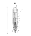
- FIG. 1 is a side sectional view of a mechanical pencil according to the present invention.
- FIG. 2 is a side sectional view of the mechanical pencil according to the present invention.
- FIG. 3 is an enlarged perspective view of the chuck body according to the present invention.
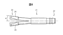
- FIG. 4 shows a side view of the chuck according to the present invention.
- FIG. 5 shows a side sectional view of the chuck body according to the present invention.
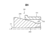
- FIG. 6 is a partial side sectional view of a chuck body according to the prior art.
- FIG. 7 is a partial sectional side view of the chuck body according to the present invention.
- FIG. 8 is a partial side sectional view of a chuck body according to the prior art.
- FIG. 9 is a graph showing the results of the core holding property test.
- FIG. 9 is a graph showing the results of the core holding property test.
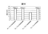
- FIG. 10 is a graph showing the results of a core breakage resistance test.
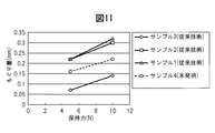
- FIG. 11 is a graph showing the results of a core boring amount test.
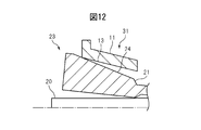
- FIG. 12 is a partial side cross-sectional view of the chuck body when a core having a large core diameter is held.
- FIG. 13 is a partial side cross-sectional view of the chuck body when a core having a small core diameter is held.
- FIG. 14 shows a partial sectional side view of a chuck body according to another embodiment of the present invention.
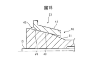
- FIG. 15 is a partial sectional side view of a chuck body according to still another embodiment of the present invention.
- FIG. 16 is a partial side sectional view of a chuck body according to still another embodiment of the present invention.
- the mechanical pencil 1 includes a knock part 2, a lead case 3, a fastener 11, a chuck 21, a spring 4, and a holding body 5 as a configuration for feeding the lead 10.
- the knock portion 2 engages with the lead case 3.
- the chuck 21 has a fitting end portion 22 that is fitted to the core case 3 and a split end portion 23 that can be put in and out of the fastener 11 in the longitudinal direction. As shown in FIG. 4, the split end 23 of the chuck 21 is configured to open upon exiting the fastener 11.
- the fastener 11 is slidably accommodated in the shaft tube 6.
- FIG. 1 and 2 differ in the positions of the fastener 11 and the chuck 21 in the mechanical pencil.
- the knock portion 2 is not pressed.
- the chuck 21 is urged toward the knock portion 2 by the spring 4 via the lead case 3. That is, the divided end portion 23 of the chuck 21 is fastened in the fastener 11.
- the split end portion 23 of the chuck 21 is closed by receiving a drag force from the fastener 11. For this reason, the core 10 is held by the chuck 21.
- the tip of the mechanical pencil 1 that is, the pen tip side is defined as the “front” side of the mechanical pencil 1, and the mechanical pencil 1 is sharpened along the longitudinal direction of the mechanical pencil 1.
- the side opposite to the pen tip of the pencil 1 is defined as the “rear” side of the mechanical pencil 1.
- the chuck body 31 includes the chuck 21 and the fastener 11.
- FIG. 3 is an enlarged perspective view of the chuck body 31 according to the present invention.
- the fastener 11 has a hollow substantially cylindrical shape.
- the material of the fastener 11 is typically brass.
- FIG. 4 shows a side view of the chuck 21 according to the present invention.
- the chuck 21 has one end 23 in the longitudinal direction divided into two symmetrically in the radial direction.
- the split end portion 23 of the chuck 21 has a tapered outer surface 24 that can enter and exit the fastener 11 and that contacts the inner surface of the fastener 11 when entering the fastener 11.
- the angle ⁇ of the tapered outer surface 24 with respect to the axis of the chuck 21 gradually decreases when the divided end portion 23 of the chuck 21 is tightened into the fastener 11.
- the split end portion 23 of the chuck 21 is closed in the fastener 11 to hold the core 10.
- the split end portion 23 of the chuck 21 may be split into three.
- FIG. 5 shows a side sectional view of the chuck body 31 according to the present invention.
- the fastener 11 has a tapered inner surface 13 in which the diameter of the hole gradually changes in the axial direction. More specifically, in the fastener 11, the diameter of the hole gradually decreases rearward in the axial direction.
- the taper angle of the taper inner surface 13 with respect to the central axis of the fastener 11 is about 3 °.
- the side on which the core 10 is held by the chuck 21 is defined as the “front” side of the chuck body 31, and the core 10 extends along the longitudinal direction of the chuck body 31.
- the side opposite to the side held by the chuck 21 is defined as the “rear” side of the chuck body 31.
- the angle of the tapered outer surface 24 of the chuck 21 with respect to the central axis of the chuck 21 is the fastener 11. Is substantially equal to the angle of the taper inner surface 13.
- the tapered outer surface 24 of the chuck 21 is in surface contact with the tapered inner surface 13 of the fastener 11.
- the center axis of the chuck 21 and the center axis of the fastener 11 are equal.
- the core 10 is moved by gravity when the axial direction of the core 10 coincides with the direction of gravity. This means that the chuck 21 does not fall off.
- FIG. 6 is a partial cross-sectional view of the chuck body 301 according to the prior art.
- FIG. 7 is a partial sectional side view of the chuck body 31 according to the present invention. Since the chuck bodies 301 and 31 have a symmetrical shape in the radial direction, only one side of the chuck bodies 301 and 31 is shown in FIGS. 6 and 7 for simplification.
- the fastener 101 according to the related art has an inner surface 103 that is straight in the axial direction. For this reason, when the chuck 201 holds the lead 10, the tapered outer surface 240 of the chuck 201 is in line contact with the inner surface 103 of the fastener 101.
- the fastener 11 has a tapered inner surface 13 in which the diameter of the hole gradually decreases rearward in the axial direction.
- the angle of the tapered outer surface 24 of the chuck 21 with respect to the central axis of the chuck 21 is substantially equal to the angle of the tapered inner surface 13 of the fastener 11 when the split end 23 of the chuck 21 is closed and the core 10 is held. .
- the tapered outer surface 24 of the chuck 21 comes into surface contact with the tapered inner surface 13 of the fastener 11.
- the holding part length L and the holding part thickness T are shown in FIG.
- the chucks of Sample 1 and Sample 2 were resin (polyacetal (POM)) chucks according to the prior art, and the chucks and fasteners had shapes as shown in FIG. Note that the POM, which is the chuck material of Sample 1, was filled with 25% glass fiber.
- Sample 3 was a metal (brass) chuck according to the prior art, and the chuck and fasteners were shaped as shown in FIG.
- Sample 4 was a resin (polyacetal) chuck according to the present invention, and the chuck and fastener had a shape as shown in FIG.
- the chucks of samples 1, 3, and 4 have the same size, and the resin chuck of sample 2 is larger than the other chucks.
- FIG. 9 is a graph showing the results of the core holding property test.
- the lead starts to slide out of the chuck with a holding force of less than 20 N, and the holding force from which the lead slides decreases as the number of knocks increases.
- the lead did not slide out of the chuck with a holding force of 25 N regardless of the number of knocks.
- the chuck body (sample 4) according to the present invention has a high core holding ability even though the chuck is a small resin chuck.
- the holding force (N) on the vertical axis of the graph of FIG. 9 represents the load applied to the chuck by only the writing pressure, and does not include the biasing force by the spring. Therefore, a load obtained by adding a biasing force (about 5 N) by the spring to the holding force was actually applied to the chuck.
- FIG. 10 is a graph showing the results of a core breakage resistance test.
- the core was damaged by the holding force of 20N.
- the other chuck bodies (samples 2 to 4), the core was not damaged even with a holding force of 30 N. From this result, it was proved that the chuck body (sample 4) according to the present invention has high core breakage resistance even though the chuck is a small resin chuck.
- FIG. 11 is a graph showing the results of a core boring amount test.
- the amount of punching of the core for the chuck body (sample 4) according to the present invention was smaller than the amount of punching of the core for the chuck body (samples 1 and 2) according to the prior art. From this result, it was proved that the chuck body (sample 4) according to the present invention has a small lead-off amount even though the chuck is a small resin chuck.
- the thickness (core diameter) of the commercial core used is not always constant. Typically, the variation in core diameter is ⁇ 0.02 mm.
- the angle of the taper outer surface 24 of the chuck 11 with respect to the center axis of the chuck 11 is such that when the split end 23 of the chuck 21 is closed and the core 10 is held, the fastener 11 deviates from the angle of the tapered inner surface 13.
- FIG. 12 is a partial side sectional view of the chuck body 31 when the core 20 having a large core diameter is held.
- FIG. 13 is a partial cross-sectional side view of the chuck body 31 when the core 30 having a small core diameter is held. For simplicity, only one side of the chuck body 31 is shown in FIGS.
- the chuck 21 according to the present invention is made of a synthetic resin having elasticity.
- the synthetic resin having elasticity include polyacetal, nylon, polypropylene, and polyethylene. Accordingly, even when the core diameter is thick or thin, the chuck 21 is appropriately deformed to follow the fastener 11, so that when the split end 23 of the chuck 21 is closed and the core 10 is held, the central axis of the chuck 21
- the angle of the tapered outer surface 24 of the chuck 21 is substantially equal to the angle of the tapered inner surface 13 of the fastener 11. Therefore, according to the chuck body 31 according to the present invention, it is possible to obtain a small amount of core unwinding and high core retention and damage resistance regardless of variations in the core diameter.
- FIG. 14 is a partial sectional side view of a chuck body 32 according to another embodiment of the present invention.
- both end portions front end portion 15 and rear end portion 16 in the axial direction of the tapered inner surface 14 of the fastener 12 are configured to be separated from the tapered outer surface 24 of the chuck 21 in the radial direction.
- both axial end portions 15 and 16 of the tapered inner surface 14 of the fastener 12 are chamfered in a tapered shape so as to be separated from the tapered outer surface 24 of the chuck 21 in the radial direction.
- the chamfered shape may be an R shape.
- FIG. 15 shows a partial side sectional view of a chuck body 33 according to still another embodiment of the present invention.
- the rear end portion of the tapered outer surface 26 of the chuck 51 is configured to be separated from the tapered inner surface 43 of the fastener 41 in the radial direction.
- the front end portion 45 in the axial direction of the tapered inner surface 43 of the fastener 41 is chamfered in a tapered shape so as to be separated from the tapered outer surface 26 of the chuck 51 in the radial direction.
- the chamfered shape may be an R shape.
- FIG. 16 shows a partial side sectional view of a chuck body 34 according to still another embodiment of the present invention.
- the length of the fastener 42 in the axial direction is long so that the rear end portion of the tapered outer surface 27 of the chuck 52 does not contact the corner of the rear end portion 48 of the tapered inner surface 44 of the fastener 42 during tightening. Is done.
- the front end portion 47 in the axial direction of the tapered inner surface 44 of the fastener 42 is chamfered in a tapered shape so as to be separated from the tapered outer surface 27 of the chuck 52 in the radial direction.
- the chamfered shape may be an R shape. With this configuration, it is possible to prevent the corners of both end portions 47 and 48 of the fastener 42 from being caught on the tapered outer surface 27 of the chuck 52, thereby preventing a poor tightening of the chuck 52.
- the chuck may be a metal chuck instead of a resin chuck.
Landscapes
- Mechanical Pencils And Projecting And Retracting Systems Therefor, And Multi-System Writing Instruments (AREA)
Abstract
本発明は、中空の略円筒形状の締め具11であって、孔の直径が軸線方向において徐々に変化するテーパー内面13を有する締め具11と、二つ又は三つに分割された分割端部23を有するチャック21であって、分割端部23が、締め具11に対して出入可能であり、且つ、締め具11内に入るときに締め具11のテーパー内面13に接触するテーパー外面24を有する、チャック21とを備えるチャック体31であって、チャック21の分割端部23が締め具11内で閉じて芯10を保持したとき、チャック21の中心軸線に対してチャック21のテーパー外面24の角度が締め具11のテーパー内面13の角度と略等しい、チャック体31を提供する。
Description
本発明は、シャープペンシルの芯を繰出し且つ保持するためのチャック体に関する。さらに、本発明は、そのチャック体を備えたシャープペンシルに関する。
シャープペンシルの芯を繰出し且つ保持するのに従来からチャック体が使用されてきた。特開2002-321493号公報に示されるように、チャック体は、チャック及び締め具(締めリング)から成る。締め具は、中空の略円筒形状であり、軸線方向に真っ直ぐな内面を有する。チャックは、長手方向の一方の端部が分割される。このチャックの分割端部は、締め具に対して出入可能であり、且つ、締め具に入るときに締め具の内面に接触するテーパー外面を有する。特開2012-158092号公報に示されるように、チャックの材料は典型的には金属又は樹脂である。
スプリングの付勢力によってチャックが締め具内に入ると、チャックのテーパー外面が締め具の内面から抗力を受けるので、チャックの分割端部が閉じて芯を保持する。筆記時には、スプリングの付勢力に加えて筆圧が芯を介してチャックに掛かるので、チャックのテーパー外面は締め具の内面から更に強い抗力を受ける。このため、芯はより強い保持力でチャックによって保持されるので、筆記時に芯が動くことが防止される。なお、締め具がテーパー内面を有し、チャックが真っ直ぐな外面を有する構成によっても同様の効果が得られることが知られている。
しかしながら、芯がチャックによって保持された状態でも、筆記開始時に筆圧によってチャックが芯と共に締め具内に押し込まれることによって、芯がペン先にもぐる。このもぐり量は、僅かな量であるが、ユーザの使用感を悪化させることがある。このため、芯のもぐり量をできるだけゼロに近づけることが望ましい。また、非常に強い筆圧が芯に加えられると、チャックによって保持されていた芯がチャックに対して滑り出し、筆記が不可能となる。さらに、本発明の説明において後述するように、チャックによる芯の保持力が局所的になることによって芯が破損することがある。この現象は芯の喰いちぎりとも呼ばれる。
チャック体のこのような芯のもぐり量、保持性及び破損耐性はチャックの材質及び大きさに依存する。剛性が高い金属チャックは、樹脂チャックよりも小さい芯のもぐり量と、樹脂チャックよりも高い芯の保持性及び破損耐性とを有することが知られている。しかしながら、金属チャックは材料費及び加工費が樹脂チャックよりも高価である。このため、金属チャックを使用する場合、安価なシャープペンシルを提供することが困難である。
また、芯を保持する樹脂チャックの分割端部を大きくすることで樹脂チャックの芯のもぐり量、保持性及び破損耐性が金属チャックの芯のもぐり量、保持性及び破損耐性に近づくことも知られている。しかしながら、外形の大きな樹脂チャックは多色軸のシャープリフィール又は細軸のシャープペンシルに使用されることができない。
そこで、本発明は、チャックの材質や大きさに拘わらず、芯のもぐり量が小さく且つ芯の保持性及び破損耐性が高いチャック体を提供することを目的とする。
本発明の第1態様では、中空の略円筒形状の締め具であって、孔の直径が軸線方向において徐々に変化するテーパー内面を有する締め具と、二つ又は三つに分割された分割端部を有するチャックであって、分割端部が、締め具に対して出入可能であり、且つ、締め具内に入るときに締め具のテーパー内面に接触するテーパー外面を有する、チャックとを備えるチャック体であって、チャックの分割端部が締め具内で閉じて芯を保持したとき、チャックの中心軸線に対してチャックのテーパー外面の角度が締め具のテーパー内面の角度と略等しい、チャック体が提供される。なお、チャックの分割端部が締め具内で閉じて芯を保持したときとは、芯の軸線方向が重力の方向と一致するときに重力によって芯がチャックから脱落しない状態を意味する。
本発明の第1態様では、チャックが、弾性を有する合成樹脂から成ることが好ましい。
本発明の第1態様では、締め具のテーパー内面の軸線方向の両端部がチャックのテーパー外面と接触しないように構成されることが好ましい。
本発明の第1態様では、締め具の両端部がチャックのテーパー外面から径方向に離れるように構成されることが好ましい。
本発明の第2態様では、本発明の第1態様のチャック体を備えた、シャープペンシルが提供される。
本発明によれば、チャックの材質や大きさに拘わらず、芯のもぐり量が小さく且つ芯の保持性及び破損耐性が高いチャック体が提供される。
以下、添付図面と本発明の好適な実施形態の記載から本発明を一層十分に理解できるであろう。
以下、添付図面を参照して本発明を説明する。また、添付図面において同一の構成要素には同一の参照符号が付される。
最初に、図1及び図2を参照して、シャープペンシル1において、芯10が繰り出される仕組みについて簡単に説明する。
図1及び図2は、本発明に係るシャープペンシル1の側断面図である。シャープペンシル1は、芯10を繰り出すための構成として、ノック部2、芯ケース3、締め具11、チャック21、スプリング4及び保持体5を備える。ノック部2は芯ケース3と係合する。チャック21は、長手方向において、芯ケース3に嵌合される嵌合端部22と、締め具11に対して出入可能な分割端部23とを有する。図4に示されるように、チャック21の分割端部23は、締め具11から出ると開くように構成される。締め具11は軸筒6内に摺動可能に収容される。
図1と図2とではシャープペンシル内における締め具11及びチャック21の位置が異なる。図1ではノック部2が押圧されていない。ノック部2が押圧されていないとき、チャック21はスプリング4によって芯ケース3を介してノック部2側に付勢される。すなわち、チャック21の分割端部23は締め具11内に締め込まれる。このとき、チャック21の分割端部23の外面と締め具11の内面とが相補的なテーパー形状を有するので、チャック21の分割端部23は締め具11から抗力を受けて閉じる。このため、芯10がチャック21によって保持される。
一方、図2に示されるようにノック部2が押圧されると、この押圧力が芯ケース3を介してチャック21に伝達される。押圧力がスプリング4の付勢力よりも大きければ、チャック21は芯10及び締め具11と共に前進する。チャック21の分割端部23が締め具11から出ると、分割端部23が開くので、芯10はチャック21から解放される。このとき、芯10は保持体5によって保持される。その後、ノック部2が離されると、チャック21の分割端部23がスプリング4の付勢力によって再び締め具11内に入るが、芯10は保持体5によって保持されるので後退しない。ノック部2の押圧を繰り返すことによって、芯10がペン先から順次繰り出される。このように、チャック21は締め具11と協働して芯10を繰出し且つ保持する。なお、図1及び図2に示されるように、本明細書において、シャープペンシル1の先端すなわちペン先側をシャープペンシル1の「前」側と定義し、シャープペンシル1の長手方向に沿ってシャープペンシル1のペン先とは反対側をシャープペンシル1の「後」側と定義する。
次に、本発明に係るチャック体31について詳細に説明する。チャック体31はチャック21及び締め具11から成る。
図3は、本発明に係るチャック体31の拡大斜視図である。締め具11は中空の略円筒形状を有する。締め具11の材料は典型的には黄銅である。
図4は、本発明に係るチャック21の側面図を示す。図4に示されるように、チャック21は、長手方向の一方の端部23が径方向に対称に二つに分割される。このチャック21の分割端部23は、締め具11に対して出入可能であり、且つ、締め具11に入るときに締め具11の内面に接触するテーパー外面24を有する。チャック21の軸線に対するテーパー外面24の角度αは、チャック21の分割端部23が締め具11内に締め込まれるとき、徐々に減少する。図3では、チャック21の分割端部23は締め具11内で閉じて芯10を保持している。なお、チャック21の分割端部23は三つに分割されてもよい。
図5は、本発明に係るチャック体31の側断面図を示す。図5に示されるように、締め具11は、孔の直径が軸線方向において徐々に変化するテーパー内面13を有する。より具体的には、締め具11は、孔の直径が軸線方向において後方に向かって徐々に減少する。このテーパー内面13の締め具11の中心軸線に対するテーパー角度は約3°である。なお、図5に示されるように、本明細書において、芯10がチャック21によって保持される側をチャック体31の「前」側と定義し、チャック体31の長手方向に沿って、芯10がチャック21によって保持される側とは反対側をチャック体31の「後」側と定義する。
図5に示されるように、チャック21の分割端部23が締め具11内で閉じて芯10を保持したとき、チャック21の中心軸線に対してチャック21のテーパー外面24の角度は締め具11のテーパー内面13の角度と略等しい。言い換えれば、チャック21の分割端部23が締め具11内で閉じて芯10を保持したとき、チャック21のテーパー外面24は締め具11のテーパー内面13と面接触する。なお、図5に示されるように、チャック21の中心軸線と締め具11の中心軸線とは等しい。また、本明細書において、チャック21の分割端部23が締め具11内で閉じて芯10を保持したときとは、芯10の軸線方向が重力の方向と一致するときに重力によって芯10がチャック21から脱落しない状態を意味する。
以下、従来技術と比較して、本発明に係るチャック体31について説明する。
図6は、従来技術に係るチャック体301の部分側断面図である。図7は、本発明に係るチャック体31の部分側断面図である。チャック体301、31は径方向に対称な形状を有するので、簡略化のために、図6及び図7ではチャック体301、31の片側のみが示される。図6に示されるように、従来技術に係る締め具101は軸線方向に真っ直ぐな内面103を有する。このため、チャック201が芯10を保持するとき、チャック201のテーパー外面240は締め具101の内面103と線接触する。この場合、チャック201と締め具101との接触面積が小さいので、チャックが芯と共に締め具内に押し込まれやすく、芯のもぐり量が大きくなる。また、チャック201のテーパー外面240が局所的に変形して、チャック201の保持部250の変形が引き起こされるので、芯10の保持性が低くなる。また、締め具101からの抗力が芯10に対して局所的に掛かるので、芯10の破損耐性が低くなる。なお、図8に示されるように、チャック202の外面204が軸線方向に真っ直ぐであり且つ締め具102の内面104がテーパー状である場合も同様な不具合が生じる。
一方、図5及び図7に示されるように、本発明に係る締め具11は、孔の直径が軸線方向において後方に向かって徐々に減少するテーパー内面13を有する。さらに、チャック21の中心軸線に対して、チャック21のテーパー外面24の角度は、チャック21の分割端部23が閉じて芯10を保持したとき、締め具11のテーパー内面13の角度と略等しい。このため、チャック21が芯10を保持するとき、チャック21のテーパー外面24は締め具11のテーパー内面13と面接触する。この場合、チャック21と締め具11との接触面積が大きいので、チャックが芯と共に締め具内に押し込まれにくく、芯のもぐり量が小さくなる。また、締め具11の内面からの抗力が分散されるので、チャック21のテーパー外面24の局所的な変形が低減され、ひいてはチャック21の保持部25の変形が低減される。このことは芯10の保持性を高める。さらに、締め具11の内面13からの抗力が芯10に対して均等に掛かるので、芯10の破損耐性が高められる。
以下、従来技術に係るチャック体と本発明に係るチャック体とを用いた、芯の保持性、破損耐性及びもぐり量に関する三つの試験の結果を示す。試験には従来技術に係る三種類のチャック体と本発明に係るチャック体の合計四種類のサンプルが使用された。使用したチャック体のチャックの概要を以下の表に示す。

保持部長さL及び保持部厚さTを図5に示す。サンプル1及びサンプル2のチャックは従来技術に係る樹脂(ポリアセタール(POM))チャックであり、チャック及び締め具は図6に示されるような形状であった。なお、サンプル1のチャックの材料であるPOMにはガラス繊維が25%充填された。サンプル3は従来技術に係る金属(黄銅)チャックであり、チャック及び締め具は図8に示されるような形状であった。サンプル4は本発明に係る樹脂(ポリアセタール)製チャックであり、チャック及び締め具は図7に示されるような形状であった。サンプル1、3、4のチャックは同等の大きさを有し、サンプル2の樹脂チャックは他のチャックよりも大きい。
芯の保持性試験
この試験では、ペン先から繰り出された芯を台秤に押し付け、芯がチャックから滑り出す荷重(保持力)を測定した。測定はノック回数毎に行われた。図9は、芯の保持性試験の結果を示すグラフである。従来技術に係るチャック体(サンプル1)では、20N未満の保持力で芯がチャックから滑り出し、ノック回数が増えるにつれて、芯が滑り出す保持力が低下した。他のチャック体(サンプル2~4)では、ノック回数によらず芯は25Nの保持力でチャックから滑り出さなかった。この結果から、本発明に係るチャック体(サンプル4)が、チャックが小さな樹脂チャックであるにも拘わらず、高い芯の保持性を有することが証明された。なお、図9のグラフの縦軸の保持力(N)は、筆圧のみによるチャックへの荷重を表し、スプリングによる付勢力を含まない。したがって、実際にチャックには、保持力にスプリングによる付勢力(約5N)を加えた荷重が加えられた。
この試験では、ペン先から繰り出された芯を台秤に押し付け、芯がチャックから滑り出す荷重(保持力)を測定した。測定はノック回数毎に行われた。図9は、芯の保持性試験の結果を示すグラフである。従来技術に係るチャック体(サンプル1)では、20N未満の保持力で芯がチャックから滑り出し、ノック回数が増えるにつれて、芯が滑り出す保持力が低下した。他のチャック体(サンプル2~4)では、ノック回数によらず芯は25Nの保持力でチャックから滑り出さなかった。この結果から、本発明に係るチャック体(サンプル4)が、チャックが小さな樹脂チャックであるにも拘わらず、高い芯の保持性を有することが証明された。なお、図9のグラフの縦軸の保持力(N)は、筆圧のみによるチャックへの荷重を表し、スプリングによる付勢力を含まない。したがって、実際にチャックには、保持力にスプリングによる付勢力(約5N)を加えた荷重が加えられた。
芯の破損耐性試験
この試験では、締め具内に入れられたチャックを後方に引っ張り、芯が破損されたときの荷重(保持力)を測定した。図10は、芯の破損耐性試験の結果を示すグラフである。従来技術に係るチャック体(サンプル1)では、20Nの保持力で芯が破損した。他のチャック体(サンプル2~4)では、30Nの保持力でも芯は破損しなかった。この結果から、本発明に係るチャック体(サンプル4)が、チャックが小さな樹脂チャックであるにも拘わらず、高い芯の破損耐性を有することが証明された。
この試験では、締め具内に入れられたチャックを後方に引っ張り、芯が破損されたときの荷重(保持力)を測定した。図10は、芯の破損耐性試験の結果を示すグラフである。従来技術に係るチャック体(サンプル1)では、20Nの保持力で芯が破損した。他のチャック体(サンプル2~4)では、30Nの保持力でも芯は破損しなかった。この結果から、本発明に係るチャック体(サンプル4)が、チャックが小さな樹脂チャックであるにも拘わらず、高い芯の破損耐性を有することが証明された。
芯のもぐり量試験
この試験では、締め具内に入れられたチャックを後方に引っ張り、荷重(保持力)毎に嵌着位置を測定した。嵌着位置とは、チャックの先端から締め具の先端までの距離であり、図5に符号Dとして示される。チャックに対するスプリングの付勢力に相当する5Nの荷重のときの嵌着位置を基準値として、基準値と荷重毎の嵌着位置との差を芯のもぐり量とした。芯のもぐりは、芯を保持したチャックが締め具に対してもぐることによって生じる。図11は、芯のもぐり量試験の結果を示すグラフである。本発明に係るチャック体(サンプル4)についての芯のもぐり量は、従来技術に係るチャック体(サンプル1及び2)についての芯のもぐり量よりも小さかった。この結果から、本発明に係るチャック体(サンプル4)が、チャックが小さな樹脂チャックであるにも拘わらず、小さい芯のもぐり量を有することが証明された。
この試験では、締め具内に入れられたチャックを後方に引っ張り、荷重(保持力)毎に嵌着位置を測定した。嵌着位置とは、チャックの先端から締め具の先端までの距離であり、図5に符号Dとして示される。チャックに対するスプリングの付勢力に相当する5Nの荷重のときの嵌着位置を基準値として、基準値と荷重毎の嵌着位置との差を芯のもぐり量とした。芯のもぐりは、芯を保持したチャックが締め具に対してもぐることによって生じる。図11は、芯のもぐり量試験の結果を示すグラフである。本発明に係るチャック体(サンプル4)についての芯のもぐり量は、従来技術に係るチャック体(サンプル1及び2)についての芯のもぐり量よりも小さかった。この結果から、本発明に係るチャック体(サンプル4)が、チャックが小さな樹脂チャックであるにも拘わらず、小さい芯のもぐり量を有することが証明された。
ところで、使用される市販の芯の太さ(芯径)は常に一定ではない。典型的には、芯径のばらつきは±0.02mmである。芯径が基準値よりも細い又は太い場合、チャック11の中心軸線に対して、チャック11のテーパー外面24の角度は、チャック21の分割端部23が閉じて芯10を保持したとき、締め具11のテーパー内面13の角度からずれる。図12は、芯径が太い芯20を保持したときのチャック体31の部分側断面図である。図13は、芯径が細い芯30を保持したときのチャック体31の部分側断面図である。簡略化のために、図12及び図13ではチャック体31の片側のみが示される。
図12に示されるように、芯径が太い場合、チャック21の分割端部23の後部が芯20と接触し、チャック21のテーパー外面24の前部が締め具11のテーパー内面13と接触する。このとき、チャック21のテーパー外面24の角度は、チャック21の中心軸線に対して、締め具11のテーパー内面13の角度からずれる。言い換えれば、チャック21のテーパー外面24は締め具11のテーパー内面13と線接触する。一方、図13に示されるように、芯径が細い場合、チャック21の分割端部23の前部が芯30と接触し、チャック21のテーパー外面24の後部が締め具11のテーパー内面13と接触する。このとき、チャック21のテーパー外面24の角度は、チャック21の中心軸線に対して、締め具11のテーパー内面13の角度からずれる。言い換えれば、チャック21のテーパー外面24は締め具11のテーパー内面13と線接触する。しかしながら、この不具合は、以下に述べる本発明の特徴によって解決される。
本発明に係るチャック21は、弾性を有する合成樹脂から成る。弾性を有する合成樹脂とは、例えば、ポリアセタール、ナイロン、ポリプロピレン、ポリエチレン等である。このことによって、芯径が太い又は細い場合も、チャック21が適度に変形して締め具11に倣うので、チャック21の分割端部23が閉じて芯10を保持したとき、チャック21の中心軸線に対してチャック21のテーパー外面24の角度は締め具11のテーパー内面13の角度と略等しくなる。したがって、本発明に係るチャック体31によれば、芯径のばらつきに拘わらず、小さい芯のもぐり量並びに高い芯の保持性及び破損耐性が得られる。
しかしながら、チャック21が弾性を有すると、締め具11のテーパー内面13の軸線方向の両端部の角がチャック21のテーパー外面24に引っ掛かり、チャック21の締め込み不良が生じることがある。この不具合は本発明の以下の構成によって解決される。
図14は、本発明の別の実施形態に係るチャック体32の部分側断面図を示す。簡略化のために、図14ではチャック体32の片側のみが示される。この実施形態では、締め具12のテーパー内面14の軸線方向の両端部(前端部15及び後端部16)は、チャック21のテーパー外面24から径方向に離れるように構成される。より具体的には、図14に示されるように、締め具12のテーパー内面14の軸線方向の両端部15、16は、チャック21のテーパー外面24から径方向に離れるようにテーパー状に面取りされる。この面取り形状はR形状であってもよい。この構成によって、締め具12の両端部15、16の角がチャック21のテーパー外面24に引っ掛かることが防止され、ひいてはチャック21の締め込み不良が防止される。
図15は、本発明の更に別の実施形態に係るチャック体33の部分側断面図を示す。簡略化のために、図15ではチャック体33の片側のみが示される。この実施形態では、チャック51のテーパー外面26の後端部が、締め具41のテーパー内面43から径方向に離れるように構成される。また、図15に示されるように、締め具41のテーパー内面43の軸線方向の前端部45は、チャック51のテーパー外面26から径方向に離れるようにテーパー状に面取りされる。この面取り形状はR形状であってもよい。この構成によって、締め具41の両端部(前端部45及び後端部46)の角がチャック51のテーパー外面26に引っ掛かることが防止され、ひいてはチャック51の締め込み不良が防止される。
図16は、本発明の更に別の実施形態に係るチャック体34の部分側断面図を示す。簡略化のために、図16ではチャック体34の片側のみが示される。この実施形態では、締め込み時にチャック52のテーパー外面27の後端部が締め具42のテーパー内面44の後端部48の角に接触しないように、締め具42の軸線方向の長さが長くされる。また、図16に示されるように、締め具42のテーパー内面44の軸線方向の前端部47は、チャック52のテーパー外面27から径方向に離れるようにテーパー状に面取りされる。この面取り形状はR形状であってもよい。この構成によって、締め具42の両端部47、48の角がチャック52のテーパー外面27に引っ掛かることが防止され、ひいてはチャック52の締め込み不良が防止される。
以上、本発明に係るいくつかの好適な実施形態を説明したが、本発明はこの実施形態に限定されるものではなく、特許請求の範囲の記載内で様々な修正及び変更を施すことができる。例えば、チャックは樹脂チャックではなく金属チャックであってもよい。また、各実施形態を互いに組み合わせて実施してもよい。
1 シャープペンシル
2 ノック部
3 芯ケース
4 スプリング
5 保持体
6 軸筒
10、20、30 芯
11、12、41、42、101、102 締め具
13、14、43、44 テーパー内面
15、45、47 前端部
16、46、48 後端部
21、51、52、201、202 チャック
22 嵌合端部
23 分割端部
24、26、27、240 テーパー外面
25、250 保持部
31、32、33、34、301、302 チャック体
103、104 締め具の内面
204 チャックの外面
2 ノック部
3 芯ケース
4 スプリング
5 保持体
6 軸筒
10、20、30 芯
11、12、41、42、101、102 締め具
13、14、43、44 テーパー内面
15、45、47 前端部
16、46、48 後端部
21、51、52、201、202 チャック
22 嵌合端部
23 分割端部
24、26、27、240 テーパー外面
25、250 保持部
31、32、33、34、301、302 チャック体
103、104 締め具の内面
204 チャックの外面
Claims (5)
- 中空の略円筒形状の締め具であって、孔の直径が軸線方向において徐々に変化するテーパー内面を有する締め具と、
二つ又は三つに分割された分割端部を有するチャックであって、該分割端部が、前記締め具に対して出入可能であり、且つ、該締め具内に入るときに前記締め具のテーパー内面に接触するテーパー外面を有する、チャックと
を備えるチャック体であって、
前記チャックの分割端部が前記締め具内で閉じて芯を保持したとき、チャックの中心軸線に対して前記チャックのテーパー外面の角度が前記締め具のテーパー内面の角度と略等しい、チャック体。 - 前記チャックが、弾性を有する合成樹脂から成る、請求項1に記載のチャック体。
- 前記締め具のテーパー内面の軸線方向の両端部が前記チャックのテーパー外面と接触しないように構成される、請求項1又は2に記載のチャック体。
- 前記締め具の前記両端部が前記チャックのテーパー外面から径方向に離れるように構成される、請求項3に記載のチャック体。
- 請求項1~4のいずれか1項に記載のチャック体を備えた、シャープペンシル。
Priority Applications (2)
| Application Number | Priority Date | Filing Date | Title |
|---|---|---|---|
| US14/647,502 US9649872B2 (en) | 2012-12-11 | 2013-12-11 | Chuck body and mechanical pencil |
| CN201380064800.3A CN104853930B (zh) | 2012-12-11 | 2013-12-11 | 夹头构件和自动铅笔 |
Applications Claiming Priority (2)
| Application Number | Priority Date | Filing Date | Title |
|---|---|---|---|
| JP2012270592 | 2012-12-11 | ||
| JP2012-270592 | 2012-12-11 |
Publications (1)
| Publication Number | Publication Date |
|---|---|
| WO2014092123A1 true WO2014092123A1 (ja) | 2014-06-19 |
Family
ID=50934409
Family Applications (1)
| Application Number | Title | Priority Date | Filing Date |
|---|---|---|---|
| PCT/JP2013/083224 Ceased WO2014092123A1 (ja) | 2012-12-11 | 2013-12-11 | チャック体及びシャープペンシル |
Country Status (5)
| Country | Link |
|---|---|
| US (1) | US9649872B2 (ja) |
| JP (1) | JP6448185B2 (ja) |
| CN (1) | CN104853930B (ja) |
| TW (1) | TWI638727B (ja) |
| WO (1) | WO2014092123A1 (ja) |
Families Citing this family (1)
| Publication number | Priority date | Publication date | Assignee | Title |
|---|---|---|---|---|
| US12082674B2 (en) | 2020-05-29 | 2024-09-10 | Gloria M. Moore | Anchor point device for hygienic epilation by threading |
Citations (2)
| Publication number | Priority date | Publication date | Assignee | Title |
|---|---|---|---|---|
| JPS6211684U (ja) * | 1985-07-08 | 1987-01-24 | ||
| JP2006315283A (ja) * | 2005-05-12 | 2006-11-24 | Sakura Color Prod Corp | シャープペンシル |
Family Cites Families (8)
| Publication number | Priority date | Publication date | Assignee | Title |
|---|---|---|---|---|
| JPS5216827Y2 (ja) * | 1974-04-25 | 1977-04-15 | ||
| JPS57162882U (ja) * | 1981-04-03 | 1982-10-14 | ||
| JPS5956085U (ja) * | 1982-10-08 | 1984-04-12 | 共栄レジン株式会社 | チヤツクを備えたシヤ−プペンシル用チヤツクリング |
| JP2002321493A (ja) | 2001-04-27 | 2002-11-05 | Suemine Takahashi | ノック式ペンシル |
| JPWO2005090094A1 (ja) * | 2004-03-19 | 2008-01-31 | 三菱鉛筆株式会社 | シャープペンシルの芯把持構造 |
| JP4847487B2 (ja) | 2008-03-26 | 2011-12-28 | 三菱鉛筆株式会社 | シャープペンシル |
| JP5874166B2 (ja) | 2011-01-31 | 2016-03-02 | ぺんてる株式会社 | シャープペンシル |
| CN102229297A (zh) * | 2011-07-01 | 2011-11-02 | 厦门高一笔业有限公司 | 一种活动铅笔用微型适配机芯 |
-
2013
- 2013-12-10 JP JP2013255314A patent/JP6448185B2/ja active Active
- 2013-12-10 TW TW102145408A patent/TWI638727B/zh active
- 2013-12-11 WO PCT/JP2013/083224 patent/WO2014092123A1/ja not_active Ceased
- 2013-12-11 CN CN201380064800.3A patent/CN104853930B/zh active Active
- 2013-12-11 US US14/647,502 patent/US9649872B2/en not_active Expired - Fee Related
Patent Citations (2)
| Publication number | Priority date | Publication date | Assignee | Title |
|---|---|---|---|---|
| JPS6211684U (ja) * | 1985-07-08 | 1987-01-24 | ||
| JP2006315283A (ja) * | 2005-05-12 | 2006-11-24 | Sakura Color Prod Corp | シャープペンシル |
Also Published As
| Publication number | Publication date |
|---|---|
| JP2014133412A (ja) | 2014-07-24 |
| TWI638727B (zh) | 2018-10-21 |
| JP6448185B2 (ja) | 2019-01-09 |
| US9649872B2 (en) | 2017-05-16 |
| CN104853930A (zh) | 2015-08-19 |
| CN104853930B (zh) | 2017-08-08 |
| TW201438930A (zh) | 2014-10-16 |
| US20150314632A1 (en) | 2015-11-05 |
Similar Documents
| Publication | Publication Date | Title |
|---|---|---|
| US8714856B2 (en) | Ballpoint pen tip, ballpoint pen refill, ballpoint pen, and method of manufacturing ballpoint pen tip | |
| US7237972B2 (en) | Automatic mechanical pencil and method of assembly thereof | |
| JP6448185B2 (ja) | チャック体及びシャープペンシル | |
| JPS6237756Y2 (ja) | ||
| US20200009899A1 (en) | Writing implement | |
| US5052838A (en) | Mechanical pencil | |
| JP6806794B2 (ja) | シャープペンシル | |
| US326737A (en) | hoffman | |
| JP6125854B2 (ja) | ボールペン | |
| JP2016163936A (ja) | ボールペンチップ及び該ボールペンチップを具備した筆記具 | |
| JPH0347907Y2 (ja) | ||
| JP2002192881A (ja) | シャープペンシル | |
| JP7368852B2 (ja) | ノックリング式筆記具 | |
| JP4855344B2 (ja) | 筆記具 | |
| JP7195206B2 (ja) | 筆記具 | |
| KR970003358Y1 (ko) | 샤아프펜슬의 슬라이더 | |
| JP7265938B2 (ja) | シャープペンシル | |
| JP2024130702A (ja) | 筆記具 | |
| JP2024130703A (ja) | 筆記具 | |
| JP2024130701A (ja) | 筆記具 | |
| US4844639A (en) | Push-type writing instrument | |
| JPH0726178U (ja) | シャープペンシル | |
| CA1119558A (en) | Press-type pencil | |
| JP2537403Y2 (ja) | プロッタ用ペンシル | |
| JP2023136459A (ja) | 芯保持装置及びこの芯保持装置を備えたシャープペンシル |
Legal Events
| Date | Code | Title | Description |
|---|---|---|---|
| 121 | Ep: the epo has been informed by wipo that ep was designated in this application |
Ref document number: 13861606 Country of ref document: EP Kind code of ref document: A1 |
|
| WWE | Wipo information: entry into national phase |
Ref document number: 14647502 Country of ref document: US |
|
| NENP | Non-entry into the national phase |
Ref country code: DE |
|
| 122 | Ep: pct application non-entry in european phase |
Ref document number: 13861606 Country of ref document: EP Kind code of ref document: A1 |