WO2014091981A1 - 電解加工工具、電解加工システム、及び孔空き部材の製造方法 - Google Patents
電解加工工具、電解加工システム、及び孔空き部材の製造方法 Download PDFInfo
- Publication number
- WO2014091981A1 WO2014091981A1 PCT/JP2013/082567 JP2013082567W WO2014091981A1 WO 2014091981 A1 WO2014091981 A1 WO 2014091981A1 JP 2013082567 W JP2013082567 W JP 2013082567W WO 2014091981 A1 WO2014091981 A1 WO 2014091981A1
- Authority
- WO
- WIPO (PCT)
- Prior art keywords
- flow path
- tool
- electrode
- electrochemical machining
- electrolytic
- Prior art date
- Legal status (The legal status is an assumption and is not a legal conclusion. Google has not performed a legal analysis and makes no representation as to the accuracy of the status listed.)
- Ceased
Links
Images


Classifications
-
- B—PERFORMING OPERATIONS; TRANSPORTING
- B23—MACHINE TOOLS; METAL-WORKING NOT OTHERWISE PROVIDED FOR
- B23H—WORKING OF METAL BY THE ACTION OF A HIGH CONCENTRATION OF ELECTRIC CURRENT ON A WORKPIECE USING AN ELECTRODE WHICH TAKES THE PLACE OF A TOOL; SUCH WORKING COMBINED WITH OTHER FORMS OF WORKING OF METAL
- B23H3/00—Electrochemical machining, i.e. removing metal by passing current between an electrode and a workpiece in the presence of an electrolyte
- B23H3/04—Electrodes specially adapted therefor or their manufacture
-
- B—PERFORMING OPERATIONS; TRANSPORTING
- B23—MACHINE TOOLS; METAL-WORKING NOT OTHERWISE PROVIDED FOR
- B23H—WORKING OF METAL BY THE ACTION OF A HIGH CONCENTRATION OF ELECTRIC CURRENT ON A WORKPIECE USING AN ELECTRODE WHICH TAKES THE PLACE OF A TOOL; SUCH WORKING COMBINED WITH OTHER FORMS OF WORKING OF METAL
- B23H7/00—Processes or apparatus applicable to both electrical discharge machining and electrochemical machining
- B23H7/26—Apparatus for moving or positioning electrode relatively to workpiece; Mounting of electrode
- B23H7/265—Mounting of one or more thin electrodes
-
- B—PERFORMING OPERATIONS; TRANSPORTING
- B23—MACHINE TOOLS; METAL-WORKING NOT OTHERWISE PROVIDED FOR
- B23H—WORKING OF METAL BY THE ACTION OF A HIGH CONCENTRATION OF ELECTRIC CURRENT ON A WORKPIECE USING AN ELECTRODE WHICH TAKES THE PLACE OF A TOOL; SUCH WORKING COMBINED WITH OTHER FORMS OF WORKING OF METAL
- B23H7/00—Processes or apparatus applicable to both electrical discharge machining and electrochemical machining
- B23H7/26—Apparatus for moving or positioning electrode relatively to workpiece; Mounting of electrode
- B23H7/30—Moving electrode in the feed direction
-
- B—PERFORMING OPERATIONS; TRANSPORTING
- B23—MACHINE TOOLS; METAL-WORKING NOT OTHERWISE PROVIDED FOR
- B23H—WORKING OF METAL BY THE ACTION OF A HIGH CONCENTRATION OF ELECTRIC CURRENT ON A WORKPIECE USING AN ELECTRODE WHICH TAKES THE PLACE OF A TOOL; SUCH WORKING COMBINED WITH OTHER FORMS OF WORKING OF METAL
- B23H9/00—Machining specially adapted for treating particular metal objects or for obtaining special effects or results on metal objects
- B23H9/10—Working turbine blades or nozzles
-
- B—PERFORMING OPERATIONS; TRANSPORTING
- B23—MACHINE TOOLS; METAL-WORKING NOT OTHERWISE PROVIDED FOR
- B23H—WORKING OF METAL BY THE ACTION OF A HIGH CONCENTRATION OF ELECTRIC CURRENT ON A WORKPIECE USING AN ELECTRODE WHICH TAKES THE PLACE OF A TOOL; SUCH WORKING COMBINED WITH OTHER FORMS OF WORKING OF METAL
- B23H9/00—Machining specially adapted for treating particular metal objects or for obtaining special effects or results on metal objects
- B23H9/14—Making holes
-
- B—PERFORMING OPERATIONS; TRANSPORTING
- B23—MACHINE TOOLS; METAL-WORKING NOT OTHERWISE PROVIDED FOR
- B23H—WORKING OF METAL BY THE ACTION OF A HIGH CONCENTRATION OF ELECTRIC CURRENT ON A WORKPIECE USING AN ELECTRODE WHICH TAKES THE PLACE OF A TOOL; SUCH WORKING COMBINED WITH OTHER FORMS OF WORKING OF METAL
- B23H9/00—Machining specially adapted for treating particular metal objects or for obtaining special effects or results on metal objects
- B23H9/14—Making holes
- B23H9/16—Making holes using an electrolytic jet
-
- Y—GENERAL TAGGING OF NEW TECHNOLOGICAL DEVELOPMENTS; GENERAL TAGGING OF CROSS-SECTIONAL TECHNOLOGIES SPANNING OVER SEVERAL SECTIONS OF THE IPC; TECHNICAL SUBJECTS COVERED BY FORMER USPC CROSS-REFERENCE ART COLLECTIONS [XRACs] AND DIGESTS
- Y02—TECHNOLOGIES OR APPLICATIONS FOR MITIGATION OR ADAPTATION AGAINST CLIMATE CHANGE
- Y02E—REDUCTION OF GREENHOUSE GAS [GHG] EMISSIONS, RELATED TO ENERGY GENERATION, TRANSMISSION OR DISTRIBUTION
- Y02E60/00—Enabling technologies; Technologies with a potential or indirect contribution to GHG emissions mitigation
- Y02E60/10—Energy storage using batteries
Definitions
- the present invention relates to an electrolytic processing tool that performs processing by electrolyzing a workpiece by energizing an electrode and the workpiece through an electrolytic solution, and an electrolytic processing system including the electrolytic processing tool.
- Drilling of difficult-to-cut materials that are difficult to machine is generally performed by electrolytic machining or electrical discharge machining.
- electrolytic processing method when drilling a difficult-to-cut material having a high aspect ratio, it is preferable to use an electrolytic processing method.
- cooling holes for circulating a cooling medium for cooling the turbine blades are formed in the turbine blades of the gas turbine.
- the shape of the cooling hole is changed to the geometry of the turbine blade. It is preferable to bend along.
- Patent Document 1 discloses an electrolytic processing assembly that enables a bent hole to be formed in a workpiece by using a curved electrode.
- the present invention provides an electrolytic machining tool, an electrolytic machining system, and a method for manufacturing a perforated member that can easily form a bent hole and a straight hole having a desired shape.
- the electrolytic processing tool is made of a conductive material having flexibility in the shape of a cylinder extending along the axis, and a flow path through which the electrolyte flows inward toward the tip side.
- the formed electrode, the insulating layer coated on the outer peripheral surface of the electrode so as to expose the tip surface of the electrode, the flow path, the first flow path including the axis, and the outer periphery of the first flow path A flow path partition section partitioned into a second flow path located on the side, and a tool body having A fluid lead-out portion is formed at a part of the circumferential position of the tool main body for leading the electrolyte flowing through the second flow path toward the radially outer side of the tool main body.
- the electrolytic solution is led out from the tip of the electrode through the flow path in the electrode.
- the workpiece is electrolyzed and the machining hole is processed deeper.
- the electrolytic solution is led out radially outward from the fluid outlet, and the derived electrolytic solution imparts a fluid working force to the inner surface of the machining hole. Accordingly, the reaction force is applied to the tool body, and the tool body is displaced so as to bend in the direction of the reaction force.
- the flow path partitioning portion is provided in the tool main body, and the flow path inside the electrode is partitioned into the first flow path and the second flow path, so that the electrolyte solution is independent of the first flow path and the second flow path. Can be distributed.
- the fluid lead-out portion communicates with the second flow path, the amount of electrolyte discharged from the fluid lead-out portion of the tool body can be adjusted by increasing or decreasing the flow rate of the electrolyte flowing through the second flow path. It is possible to easily adjust the amount of displacement of the tool body.
- the electrolytic processing tool according to the second aspect of the present invention further includes a plug part that is provided in the electrode in the first aspect and closes the second flow path, and the fluid outlet part includes the You may form in the rear-end side of the said tool main body rather than the stopper part.
- the flow rate of the electrolyte flowing through the second flow path becomes equal to the flow rate of the electrolyte discharged from the fluid outlet portion toward the radially outer side. For this reason, it is easier to adjust the flow rate of the electrolytic solution derived from the fluid deriving unit. Therefore, it is possible to more easily form a bent hole and a straight hole having a desired shape by controlling the reaction force of the fluid acting force applied to the tool body.
- the electrolytic processing system is the electrolytic processing tool according to the first aspect or the second aspect, and the electrolytic processing tool is in a predetermined traveling direction with respect to the workpiece.
- the electrolytic solution in the electrolytic processing tool, can be circulated independently in the first flow path and the second flow path by providing the flow path partition portion in the tool body. Therefore, the amount of displacement of the tool body can be easily adjusted by increasing or decreasing the flow rate of the electrolyte flowing through the second flow path and adjusting the amount derived from the fluid outlet. Therefore, it is possible to easily form a bent hole and a straight hole having a desired shape.
- a machining hole is formed in a workpiece using the electrolytic machining tool according to the first aspect or the second aspect.
- the displacement of the tool main body is adjusted by increasing or decreasing the flow rate of the electrolyte flowing through the second flow path by the electrolytic processing tool and adjusting the amount derived from the fluid outlet portion.
- the amount can be easily adjusted. Therefore, it is possible to easily form a bent hole and a straight hole having a desired shape.
- the first flow path and the second flow path are partitioned in the tool body, and the second flow path communicates with the fluid outlet portion. . Therefore, it is possible to easily form a bent hole and a straight hole having a desired shape.
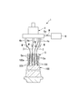
- the electrolytic processing system 1 is an apparatus for forming a processing hole 101 in a workpiece 100.
- the workpiece 100 is a turbine blade of a gas turbine
- the machining hole 101 of the workpiece 100 is a cooling hole for cooling the turbine blade.
- the manufacturing method of the workpiece 100 having the processing hole 101 that is, the manufacturing method of the perforated member will be described.
- the electrolytic processing system 1 includes a plurality of electrolytic processing tools 3 that form processing holes 101 in a workpiece 100, a moving mechanism 4 that advances the electrolytic processing tools 3, and an electrolytic processing tool 3.
- the electrolytic processing system 1 may have a configuration including not only a configuration including a plurality of electrolytic processing tools 3 but also a single electrolytic processing tool 3.
- the moving mechanism 4 is disposed on the tip 100 a side of the turbine blade that is the workpiece 100.
- the moving mechanism 4 allows the electrolytic processing tool 3 to move forward and backward with respect to the tip 100a.
- the moving mechanism 4 moves the electrolytic processing tool 3 forward and backward using a driving source such as an electric motor (not shown).
- the moving mechanism 4 has a plurality of gripping portions 4a for gripping the base end (base end 10b described later) of the electrolytic processing tool 3 on the surface on the workpiece 100 side.
- the grip portion 4a has a cylindrical shape with a hollow inside. The base end of the electrolytic processing tool 3 is inserted into one end side of the grip portion 4a, and the electrolytic processing tool 3 is gripped.
- the electrolytic solution supply unit 6 is a pump or the like, and is connected to the other end side of the gripping unit 4a of the moving mechanism 4 via the electrolytic solution passage 6a.
- the electrolyte solution W is supplied into the grip portion 4a through the electrolyte flow passage 6a.
- the supply amount of the electrolytic solution W is arbitrarily adjusted by a flow rate control device (not shown).
- As the electrolytic solution W for example, sulfuric acid, nitric acid, saline, or the like is used.
- the guide unit 5 is disposed between the moving mechanism 4 and the tip 100a of the workpiece 100 (the tip shroud of the turbine blade).
- the guide unit 5 guides the electrochemical machining tool 3 advanced / retreated by the moving mechanism 4 with respect to the tip 100a of the workpiece 100 so as to be in a predetermined traveling direction.
- the guide portion 5 is provided with a plurality of guide holes 5a that allow the moving mechanism 4 side and the workpiece 100 side to communicate with each other.
- the electrolytic machining tool 3 is inserted through the guide holes 5a from the moving mechanism 4 side toward the workpiece 100 side.
- the electrolytic processing tool 3 is advanced by the moving mechanism 4, so that the processing tool 100 is moved to a desired position on the distal end 100a of the workpiece 100 in accordance with the arrangement of the guide holes 5a and desired with respect to the distal end 100a.
- the electrochemical machining tool 3 can be introduced at an angle of
- the electrolytic processing tool 3 forms a machining hole (turbine blade cooling hole) 101 in a workpiece 100 by electrolytic machining.
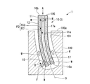
- the electrolytic processing tool 3 includes an electrode 11 and an insulating layer 12 that covers the electrode 11 from the outer periphery, and includes a tool body 10 that has a cylindrical shape as a whole.
- the electrode 11 in the tool body 10 has a cylindrical shape extending along the axis O.
- the electrode 11 is formed of a conductive material having flexibility such as stainless steel, copper, and titanium.
- a space communicating with the inside of the grip portion 4 a of the moving mechanism 4 is formed in the hollow portion inside the electrode 11 (inside the electrode 11).
- This space is a flow path FC through which the electrolytic solution W used for electrolytic processing is introduced and circulated from the inside of the grip portion 4a.
- the electrolyte solution W flows from the base end 10b side (moving mechanism 4 side), which is the rear end side of the tool body 10, toward the tip end 10a side (workpiece 100 side).
- the end face of the electrode 11 on the tip 10a side is flat or tapered perpendicular to the axis O (flat in this embodiment).
- the electrode 11 has a cylindrical shape, but may have, for example, a rectangular shape with a polygonal cross section.
- the insulating layer 12 in the tool body 10 is made of, for example, a polyester resin having electrical insulation.
- the insulating layer 12 is covered on the outer peripheral surface of the electrode 11. However, the end surface of the electrode 11 on the tip 10a side is not covered with the insulating layer 12, and the electrode 11 is exposed.
- the electrolyte solution W flowing through the flow path FC inside the electrode 11 is directed to the radially outer side of the tool body 10 at a part of the circumferential position.
- the fluid lead-out part 15 led out is formed.
- a hole that penetrates the electrode 11 and the insulating layer 12 in the radial direction and communicates the inside and outside of the tool body 10 is employed as the fluid outlet 15.
- the shape of the fluid lead-out portion 15 viewed from the radial direction of the tool body 10 is a rectangular shape configured with a line segment extending in the circumferential direction and the axis O direction as a side.
- the shape of the hole is not limited to a rectangular shape, and may be another shape such as a circular shape or a square shape.
- leading-out part 15 is formed in the position near the front-end
- the tool body 10 further includes an inner cylinder member (flow path partitioning portion) 17 disposed inside the electrode 11.
- the inner cylinder member 17 extends along the axis O and has a cylindrical shape having the same dimension in the direction of the axis O as the electrode 11.
- the inner cylinder member 17 is formed of a conductive material having flexibility, such as stainless steel, copper, and titanium.
- the inner cylindrical member 17 is supported on the inner peripheral surface 11a with a radial gap from the inner peripheral surface 11a of the electrode 11 by, for example, ribs.
- the rib is provided so as to protrude radially inward from the inner peripheral surface 11a of the electrode 11 with an interval in the direction of the axis O and the peripheral direction, and fixes the outer peripheral surface 17a of the inner cylinder member 17. .
- the inner cylinder member 17 is not limited to the case where the inner cylinder member 17 is formed of a conductive material. However, the inner cylinder member 17 is preferably formed of a conductive material so that the inner cylinder member 17 can provide the electrolytic effect on the tip 10a side. preferable. Moreover, in this embodiment, although the inner cylinder member 17 has comprised the cylindrical shape, you may comprise the square cylinder shape of a cross-sectional polygon, for example.
- the inner cylinder member 17 divides the flow path FC formed inside the electrode 11 into two, the first flow path FC1 and the second flow path FC2. That is, the first flow path FC1 is a columnar space centered on the axis O including the axis O.
- the second flow path FC ⁇ b> 2 is an annular space centered on the axis O defined between the outer peripheral surface 17 a of the inner cylinder member 17 and the inner peripheral surface 11 a of the electrode 11. Therefore, the fluid outlet 15 communicates the second flow path FC2 with the outside of the tool body 10.
- the first flow path FC1 and the second flow path FC2 are supplied with the electrolyte solution W whose flow rate is independently controlled from the above-described electrolyte supply section 6, and the first flow path FC1 and the second flow path FC2 are respectively supplied.
- the electrolytic solution W circulates.
- the electrolytic solution W is led out from the tip 10a of the tool body 10 by the electrolytic processing tool 3 through the first flow path FC1 and the second flow path FC2. And it supplies with electricity between the end surface of the front-end
- the workpiece 100 is electrolyzed and the machining hole 101 is machined deeper in the direction of the axis O.
- the electrolytic solution W supplied from the electrolytic solution supply unit 6 and circulated through the first flow path FC1 is led out from the tip 10a of the tool body 10 toward the workpiece 100 as it is.
- part of the electrolytic solution W that has circulated through the second flow path FC2 is radially outward from the fluid outlet 15, that is, toward the inner surface of the machining hole 101 of the workpiece 100. 10 is derived.
- the remainder of the electrolyte W that is not led out from the fluid lead-out part 15 is led out from the tip 10a of the tool body 10 toward the workpiece 100.
- the electrolytic solution W derived from the fluid deriving unit 15 imparts a fluid working force to the inner surface of the processing hole 101.
- the reaction force F of the fluid action force is applied to the tool body 10 and the tool body 10 is displaced so as to bend in the direction of the reaction force F.
- the flow path FC is divided into a first flow path FC1 and a second flow path FC2.
- the electrolyte solution W can be independently supplied to the first channel FC1 and the second channel FC2 by the electrolyte solution supply unit 6. Accordingly, the flow rate of the electrolytic solution W to each of the first flow path FC1 and the second flow path FC2 can be independently controlled.
- the amount of the electrolytic solution W derived from the fluid deriving unit 15 can be increased.
- the reaction force F from the workpiece 100 given to the tool main body 10 can be increased.
- the amount of displacement of the tool body 10 can be easily increased, and the processing hole 101 can be formed as a curved bent hole by unevenly distributing the current density distribution in the bending direction.
- the reaction force F can be reduced, and the machining hole 101 with a small degree of curvature can be easily formed.
- the processing hole 101 as a linear hole can be formed by stopping the supply of the electrolyte solution W to the second flow path FC2.
- the degree of curvature of the tool body 10 can be easily adjusted by appropriately adjusting the supply amount of the electrolyte W to the second flow path FC2. Therefore, it is possible to process a straight hole and a bent hole with one electrolytic processing tool 3. Further, when forming the machining hole, by appropriately adjusting the degree of curvature of the tool body 10, it is possible to form the machining hole 101 having a complicated shape in which straight holes and curved holes are mixed.
- the flow path FC is divided into the first flow path FC 1 and the second flow path FC 2 by the inner cylinder member 17, and the second flow path FC 2 communicates with the fluid outlet 15. Therefore, the processed hole 101 can be easily formed as a bent hole and a straight hole having a desired shape.
- the inner cylinder member 17 is supported on the inner peripheral surface 11a of the electrode 11 by a rib or the like as described above. However, if the inner cylinder member 17 can be held in a state where the inner peripheral surface 11a of the electrode 11 and the inner cylinder member 17 are separated when the electrolyte solution W is circulated, a support structure such as a rib is not provided. It is not necessary to provide it.
- the tool body 10 further includes a plug member 23 that is provided in the inner cylinder member 17 and closes the second flow path FC2 with the tip 10a of the tool body 10.
- the plug member 23 is provided between the first flow path FC1 and the inner peripheral surface 11a of the electrode 11 at the tip 10a of the tool body 10, and the electrolytic solution W from the second flow path FC2 is provided. It is a closing member having an annular shape around the axis O that prevents the lead-out.
- the plug member 23 is provided closer to the tip 10 a than the fluid outlet 15. In other words, the fluid outlet 15 is formed closer to the base end 10 b than the plug member 23.
- the plug member 23 closes the second flow path FC2 with the tip 10a. For this reason, it is possible to derive all of the electrolytic solution W from the fluid deriving unit 15.
- the flow rate adjustment of the electrolytic solution W derived from the fluid deriving unit 15 toward the radially outer side becomes easier. Therefore, the reaction force of the fluid acting force applied to the tool body can be controlled, and the bent hole and the straight hole having a desired shape can be formed more easily.
- the plug member 23 is provided at the tip 10a of the tool body 10, but is not limited to such an installation position, and may be provided at least at the tip 10a side from the fluid outlet 15; It is only necessary that all of the electrolyte W flowing through the second flow path FC2 can be derived from the fluid deriving unit 15.
- the plug member 23 may be formed integrally with the inner cylinder member 17. Further, instead of the plug member 23, for example, a resin or the like may be filled so that the gap between the first flow path FC1 and the second flow path FC2 is closed on the tip 10a side with respect to the fluid outlet portion 15.
- the electrode 11 may be exposed by forming a portion where the insulating layer 12 is not provided on the outer peripheral surface of the electrode 11 at a position 180 degrees apart from the fluid outlet 15 around the axis O.
- the reaction force F current is passed between the exposed portion of the outer peripheral surface and the inner surface of the machining hole 101.
- electrolysis of the machining hole 101 can be promoted on the side where the tool body 10 is curved, and the efficiency of forming the bent hole can be improved.
- the electrolytic processing tool 3 needs to be rotated. There is a possibility that the tip 10a of the main body 10 vibrates and the short-circuit frequency at the exposed portion increases.
- the flow path FC is divided into a first flow path FC1 and a second flow path FC2, and the displacement of the tool body is controlled by controlling the amount of electrolyte W derived from the fluid deriving section 15. Can be easily controlled, so that the frequency of short-circuiting during straight hole drilling can be reduced.
- the first flow path and the second flow path are partitioned in the tool body, and the second flow path communicates with the fluid outlet portion.
- the second flow path communicates with the fluid outlet portion.
- Electrolytic processing system 3 Electrolytic processing tool 4 Movement mechanism 4a Gripping part 5 Guide part 5a Guide hole 6 Electrolyte supply part 6a Electrolyte flow path 10 Tool main body 10a Tip 10b Base end 11 Electrode 11a Inner peripheral surface 12 Insulating layer 15 Fluid derivation Part 17 Inner cylinder member (channel partition) 17a Outer peripheral surface 100 Work material 100a Tip 101 Processing hole O Axis line W Electrolyte FC flow path FC1 First flow path FC2 Second flow path F Reaction force 21 Electrolytic processing system 23 Plug member
Landscapes
- Engineering & Computer Science (AREA)
- Mechanical Engineering (AREA)
- Physics & Mathematics (AREA)
- Thermal Sciences (AREA)
- Chemical & Material Sciences (AREA)
- Chemical Kinetics & Catalysis (AREA)
- Electrochemistry (AREA)
- Manufacturing & Machinery (AREA)
- Electrical Discharge Machining, Electrochemical Machining, And Combined Machining (AREA)
Abstract
Description
本願は、2012年12月12日に出願された特願2012-271436号に基づき優先権を主張し、その内容をここに援用する。
前記工具本体の周方向位置の一部に、前記第二流路を流通する前記電解液を前記工具本体の径方向外側に向かって導出する流体導出部が形成されている。
ここで、流路区画部を工具本体に設け、電極の内側の流路を第一流路と第二流路とに区画したことによって、第一流路と第二流路とに独立して電解液を流通させることが可能となる。また、流体導出部は第二流路に通じているため、第二流路へ流通させる電解液の流量を増減させることで工具本体の流体導出部からの電解液の導出量を調整することができ、工具本体の変位量を容易に調整可能となる。
以下、本発明の第一実施形態に係る電解加工システム1について説明する。
電解加工システム1は、被加工材100に加工孔101を形成するための装置である。本実施形態では一例として、被加工材100はガスタービンのタービン翼であり、被加工材100の加工孔101は、タービン翼を冷却するための冷却孔となっている。
以下、加工孔101を有する被加工材100の製造方法、即ち、孔空き部材の製造方法を交えて説明する。
図2A及び図2Bに示すように、電解加工工具3は、被加工材100に加工孔(タービン翼の冷却孔)101を電解加工により形成するものである。電解加工工具3は、電極11、及びこの電極11を外周から覆う絶縁層12を有して、全体として筒状をなす工具本体10を備えている。
このリブは図示しないが、例えば、電極11の内周面11aから軸線O方向、周方向に間隔をあけて径方向内側に向かって突出して設けられ、内筒部材17の外周面17aを固定する。
従って、流体導出部15は、第二流路FC2と工具本体10の外部とを連通している。
次に、本発明の第二実施形態に係る電解加工システム21について説明する。
なお、第一実施形態と共通の構成要素には同一の符号を付して詳細説明を省略する。
本実施形態では、内筒部材17に設けられて、第二流路FC2を工具本体10の先端10aで閉塞する栓部材23を、工具本体10がさらに有している。
例えば、流体導出部15とは軸線O回りに180度離間した位置における電極11の外周面に、絶縁層12を設けない部分を形成して電極11を露出させてもよい。このようにすることで、反力Fを受けて工具本体10が湾曲した際には、この外周面の露出部分と加工孔101の内面との間で通電する。このため、工具本体10が湾曲した側で加工孔101の電解を促進でき、曲がり孔の形成の効率化を図ることができる。
3 電解加工工具
4 移動機構
4a 把持部
5 ガイド部
5a ガイド孔
6 電解液供給部
6a 電解液流通路
10 工具本体
10a 先端
10b 基端
11 電極
11a 内周面
12 絶縁層
15 流体導出部
17 内筒部材(流路区画部)
17a 外周面
100 被加工材
100a 先端
101 加工孔
O 軸線
W 電解液
FC 流路
FC1 第一流路
FC2 第二流路
F 反力
21 電解加工システム
23 栓部材
Claims (4)
- 軸線に沿って延びる筒状をなして可撓性を有する導電性材料からなり、内側に先端側に向かって電解液が流通する流路が形成された電極と、
該電極の先端面を露出させるように該電極の外周面に被覆された絶縁層と、
前記流路を、前記軸線を含む第一流路、及び、該第一流路の外周側に位置する第二流路に区画する流路区画部と、
を有する工具本体を備え、
前記工具本体の周方向位置の一部に、前記第二流路を流通する前記電解液を前記工具本体の径方向外側に向かって導出する流体導出部が形成されている電解加工工具。 - 前記電極内に設けられ、前記第二流路を閉塞する栓部をさらに備え、
前記流体導出部は、前記栓部よりも前記工具本体の後端側に形成されている請求項1に記載の電解加工工具。 - 請求項1又は2に記載の電解加工工具と、
前記電解加工工具を被加工材に対して所定の進行方向となるように案内するガイド部と、
前記電解加工工具を進行させる移動機構と、
前記第一流路及び前記第二流路の各々に独立に前記電解液を供給する電解液供給部と、
を備える電解加工システム。 - 請求項1又は2に記載の電解加工工具を用いて被加工材に加工孔を形成する孔空き部材の製造方法。
Priority Applications (4)
| Application Number | Priority Date | Filing Date | Title |
|---|---|---|---|
| US14/443,754 US9878388B2 (en) | 2012-12-12 | 2013-12-04 | Electrochemical machining tool, electrochemical machining system, and perforated member manufacturing method |
| KR1020157013407A KR101676978B1 (ko) | 2012-12-12 | 2013-12-04 | 전해 가공 공구, 전해 가공 시스템, 및 천공 부재의 제조 방법 |
| DE112013005944.4T DE112013005944B4 (de) | 2012-12-12 | 2013-12-04 | Werkzeug zur elektrochemischen Bearbeitung, System zur elektrochemischen Bearbeitung und Verfahren zum Herstellen eines Elements mit einer Bohrung |
| CN201380056451.0A CN104755215B (zh) | 2012-12-12 | 2013-12-04 | 电解加工工具、电解加工系统以及穿孔构件的制造方法 |
Applications Claiming Priority (2)
| Application Number | Priority Date | Filing Date | Title |
|---|---|---|---|
| JP2012-271436 | 2012-12-12 | ||
| JP2012271436A JP5955207B2 (ja) | 2012-12-12 | 2012-12-12 | 電解加工工具、電解加工システム、及び孔空き部材の製造方法 |
Publications (1)
| Publication Number | Publication Date |
|---|---|
| WO2014091981A1 true WO2014091981A1 (ja) | 2014-06-19 |
Family
ID=50934273
Family Applications (1)
| Application Number | Title | Priority Date | Filing Date |
|---|---|---|---|
| PCT/JP2013/082567 Ceased WO2014091981A1 (ja) | 2012-12-12 | 2013-12-04 | 電解加工工具、電解加工システム、及び孔空き部材の製造方法 |
Country Status (6)
| Country | Link |
|---|---|
| US (1) | US9878388B2 (ja) |
| JP (1) | JP5955207B2 (ja) |
| KR (1) | KR101676978B1 (ja) |
| CN (1) | CN104755215B (ja) |
| DE (1) | DE112013005944B4 (ja) |
| WO (1) | WO2014091981A1 (ja) |
Cited By (1)
| Publication number | Priority date | Publication date | Assignee | Title |
|---|---|---|---|---|
| US10245666B2 (en) * | 2016-06-30 | 2019-04-02 | General Electric Company | Drilling tool for use in machining a conductive work piece |
Families Citing this family (22)
| Publication number | Priority date | Publication date | Assignee | Title |
|---|---|---|---|---|
| JP6071742B2 (ja) * | 2013-05-16 | 2017-02-01 | 三菱重工業株式会社 | 電解加工工具、電解加工システム、及び孔空き部材の製造方法 |
| US9976227B2 (en) * | 2014-05-15 | 2018-05-22 | Baker Hughes, A Ge Company, Llc | Electrochemical machining method for rotors or stators for moineau pumps |
| CN104759721B (zh) * | 2015-03-23 | 2017-03-15 | 宁波大红鹰学院 | 自导向弯直孔电解加工装置的加工方法 |
| US9827628B2 (en) * | 2015-03-27 | 2017-11-28 | General Electric Company | Fixture for electro-chemical machining electrode |
| US9943920B2 (en) | 2015-03-27 | 2018-04-17 | General Electric Company | Method for electro-chemical machining turbine wheel in-situ |
| US9925609B2 (en) * | 2015-07-30 | 2018-03-27 | General Electric Company | Drilling tool and method of machining a conductive work piece |
| US9943921B2 (en) * | 2015-07-30 | 2018-04-17 | General Electric Company | Electrochemical machining system and method of machining a conductive work piece |
| CN106552975B (zh) * | 2015-09-28 | 2019-01-01 | 通用电气公司 | 加工工具和加工系统 |
| CN106735639B (zh) * | 2016-12-19 | 2019-06-28 | 深圳大学 | 一种可变形的工具电极的电解加工工艺及其装置 |
| JP6754001B2 (ja) * | 2017-03-31 | 2020-09-09 | 本田技研工業株式会社 | 表面処理装置 |
| JP7141816B2 (ja) | 2017-07-18 | 2022-09-26 | 三菱重工業株式会社 | 電解加工方法、孔あき部材の製造方法、加工用電極、及び、電解加工システム |
| JP6655589B2 (ja) | 2017-11-29 | 2020-02-26 | 三菱重工業株式会社 | 計測システム、加工システム、計測方法及びプログラム |
| CN108672863A (zh) * | 2018-07-31 | 2018-10-19 | 中北大学 | 利用小孔反流排除电蚀产物的电极管 |
| CN109570667B (zh) * | 2019-01-18 | 2023-08-15 | 广西玉柴机器股份有限公司 | 一种气缸体电解去毛刺装置 |
| FR3092508B1 (fr) | 2019-02-12 | 2021-09-10 | Safran Aircraft Engines | Procede de percage d’un trou dans une piece en materiau electroconducteur |
| CN110842307B (zh) * | 2019-11-22 | 2020-07-17 | 合肥工业大学 | 一种针对可达性差复杂内壁结构的电解加工工具 |
| CN111014765B (zh) * | 2019-12-18 | 2022-03-22 | 广东轻工职业技术学院 | 一种软轴驱动的空间螺旋孔加工装置 |
| CN111408804B (zh) * | 2020-04-28 | 2020-12-18 | 常州工学院 | 一种调隙式弯孔电解加工装置及方法 |
| CN113478031B (zh) * | 2021-07-28 | 2022-06-10 | 南京航空航天大学 | 柔性电极动态变形电解加工方法及应用 |
| CN114346592A (zh) * | 2021-11-18 | 2022-04-15 | 武汉船用机械有限责任公司 | 具有曲线孔的矩形导轨工件的加工方法 |
| US11980959B2 (en) * | 2022-03-09 | 2024-05-14 | Textron Innovations Inc. | Electrochemical machining of geometrically complex passages |
| US20230347434A1 (en) * | 2022-04-28 | 2023-11-02 | Rolls-Royce Corporation | Pulsed electrochemical machining of turbine components |
Citations (3)
| Publication number | Priority date | Publication date | Assignee | Title |
|---|---|---|---|---|
| US20090134136A1 (en) * | 2007-11-23 | 2009-05-28 | Siemens Aktiengesellschaft | Apparatus and method to machine holes |
| JP2011177819A (ja) * | 2010-02-26 | 2011-09-15 | Mitsubishi Heavy Ind Ltd | 動作状態診断システム、監視装置、制御方法、及びプログラム |
| JP2012035369A (ja) * | 2010-08-06 | 2012-02-23 | Mitsubishi Heavy Ind Ltd | 電解加工装置 |
Family Cites Families (10)
| Publication number | Priority date | Publication date | Assignee | Title |
|---|---|---|---|---|
| GB1130561A (en) | 1964-09-04 | 1968-10-16 | Rolls Royce | Electrolytic drilling |
| JPS5033025A (ja) | 1973-07-31 | 1975-03-31 | ||
| GB8907252D0 (en) * | 1989-03-31 | 1989-05-17 | Lucas Ind Plc | Forming passages in workpieces |
| JPH0751948A (ja) | 1993-08-05 | 1995-02-28 | Nissan Motor Co Ltd | 曲がり穴加工方法および曲がり穴加工装置 |
| DE19929023A1 (de) | 1999-06-25 | 2000-09-28 | Bosch Gmbh Robert | Elektrode zur elektrochemischen Materialbearbeitung |
| JP2001205523A (ja) | 2000-01-25 | 2001-07-31 | Mitsubishi Electric Corp | 曲がり穴加工装置及び曲がり穴加工方法 |
| CN101015874A (zh) | 2007-03-09 | 2007-08-15 | 清华大学 | 一种弯曲孔的电火花/电解加工方法及其装置 |
| US8535491B2 (en) | 2009-09-18 | 2013-09-17 | General Electric Company | Electrochemical machining assembly with curved electrode |
| JP6139860B2 (ja) * | 2011-11-29 | 2017-05-31 | 三菱重工業株式会社 | 電解加工工具及び電解加工システム |
| AT512987B1 (de) | 2012-06-04 | 2015-03-15 | Schoeller Bleckmann Oilfield Technology Gmbh | Funkenerosions-Werkzeug und Elektrode für ein Funkenerosions-Werkzeug |
-
2012
- 2012-12-12 JP JP2012271436A patent/JP5955207B2/ja active Active
-
2013
- 2013-12-04 US US14/443,754 patent/US9878388B2/en active Active
- 2013-12-04 KR KR1020157013407A patent/KR101676978B1/ko active Active
- 2013-12-04 WO PCT/JP2013/082567 patent/WO2014091981A1/ja not_active Ceased
- 2013-12-04 DE DE112013005944.4T patent/DE112013005944B4/de active Active
- 2013-12-04 CN CN201380056451.0A patent/CN104755215B/zh active Active
Patent Citations (3)
| Publication number | Priority date | Publication date | Assignee | Title |
|---|---|---|---|---|
| US20090134136A1 (en) * | 2007-11-23 | 2009-05-28 | Siemens Aktiengesellschaft | Apparatus and method to machine holes |
| JP2011177819A (ja) * | 2010-02-26 | 2011-09-15 | Mitsubishi Heavy Ind Ltd | 動作状態診断システム、監視装置、制御方法、及びプログラム |
| JP2012035369A (ja) * | 2010-08-06 | 2012-02-23 | Mitsubishi Heavy Ind Ltd | 電解加工装置 |
Cited By (2)
| Publication number | Priority date | Publication date | Assignee | Title |
|---|---|---|---|---|
| US10245666B2 (en) * | 2016-06-30 | 2019-04-02 | General Electric Company | Drilling tool for use in machining a conductive work piece |
| US11241751B2 (en) | 2016-06-30 | 2022-02-08 | General Electric Company | Drilling tool for use in machining a conductive work piece |
Also Published As
| Publication number | Publication date |
|---|---|
| KR101676978B1 (ko) | 2016-11-16 |
| US20150273602A1 (en) | 2015-10-01 |
| CN104755215A (zh) | 2015-07-01 |
| KR20150064229A (ko) | 2015-06-10 |
| DE112013005944T5 (de) | 2015-09-10 |
| JP5955207B2 (ja) | 2016-07-20 |
| DE112013005944B4 (de) | 2023-06-22 |
| US9878388B2 (en) | 2018-01-30 |
| CN104755215B (zh) | 2016-10-12 |
| JP2014113678A (ja) | 2014-06-26 |
Similar Documents
| Publication | Publication Date | Title |
|---|---|---|
| JP5955207B2 (ja) | 電解加工工具、電解加工システム、及び孔空き部材の製造方法 | |
| JP6008792B2 (ja) | 電解加工工具、及び電解加工システム | |
| JP6139860B2 (ja) | 電解加工工具及び電解加工システム | |
| JP6071742B2 (ja) | 電解加工工具、電解加工システム、及び孔空き部材の製造方法 | |
| JP5727738B2 (ja) | 湾曲電極及び電解加工法並びにこれを利用した組立体 | |
| JP2013544195A (ja) | 電極ホルダ | |
| JP5940427B2 (ja) | 電解加工工具及び電解加工システム | |
| TWI604905B (zh) | 難加工材料之放電輔助切削加工裝置 | |
| JP2016187850A (ja) | 電解加工工具 | |
| JP7141816B2 (ja) | 電解加工方法、孔あき部材の製造方法、加工用電極、及び、電解加工システム | |
| US20190270152A1 (en) | Electrode for an electro-erosion process and an associated method thereof | |
| CN109382556A (zh) | 一种带有楔形的电火花加工电极 |
Legal Events
| Date | Code | Title | Description |
|---|---|---|---|
| 121 | Ep: the epo has been informed by wipo that ep was designated in this application |
Ref document number: 13862716 Country of ref document: EP Kind code of ref document: A1 |
|
| WWE | Wipo information: entry into national phase |
Ref document number: 14443754 Country of ref document: US |
|
| ENP | Entry into the national phase |
Ref document number: 20157013407 Country of ref document: KR Kind code of ref document: A |
|
| WWE | Wipo information: entry into national phase |
Ref document number: 112013005944 Country of ref document: DE Ref document number: 1120130059444 Country of ref document: DE |
|
| 122 | Ep: pct application non-entry in european phase |
Ref document number: 13862716 Country of ref document: EP Kind code of ref document: A1 |