WO2014091925A1 - 蓄電デバイスおよびその製造方法 - Google Patents
蓄電デバイスおよびその製造方法 Download PDFInfo
- Publication number
- WO2014091925A1 WO2014091925A1 PCT/JP2013/081847 JP2013081847W WO2014091925A1 WO 2014091925 A1 WO2014091925 A1 WO 2014091925A1 JP 2013081847 W JP2013081847 W JP 2013081847W WO 2014091925 A1 WO2014091925 A1 WO 2014091925A1
- Authority
- WO
- WIPO (PCT)
- Prior art keywords
- positive electrode
- negative electrode
- active material
- electrode active
- material layer
- Prior art date
- Legal status (The legal status is an assumption and is not a legal conclusion. Google has not performed a legal analysis and makes no representation as to the accuracy of the status listed.)
- Ceased
Links
Images








Classifications
-
- H—ELECTRICITY
- H01—ELECTRIC ELEMENTS
- H01M—PROCESSES OR MEANS, e.g. BATTERIES, FOR THE DIRECT CONVERSION OF CHEMICAL ENERGY INTO ELECTRICAL ENERGY
- H01M10/00—Secondary cells; Manufacture thereof
- H01M10/05—Accumulators with non-aqueous electrolyte
- H01M10/058—Construction or manufacture
-
- H—ELECTRICITY
- H01—ELECTRIC ELEMENTS
- H01G—CAPACITORS; CAPACITORS, RECTIFIERS, DETECTORS, SWITCHING DEVICES, LIGHT-SENSITIVE OR TEMPERATURE-SENSITIVE DEVICES OF THE ELECTROLYTIC TYPE
- H01G11/00—Hybrid capacitors, i.e. capacitors having different positive and negative electrodes; Electric double-layer [EDL] capacitors; Processes for the manufacture thereof or of parts thereof
- H01G11/22—Electrodes
- H01G11/26—Electrodes characterised by their structure, e.g. multi-layered, porosity or surface features
-
- H—ELECTRICITY
- H01—ELECTRIC ELEMENTS
- H01G—CAPACITORS; CAPACITORS, RECTIFIERS, DETECTORS, SWITCHING DEVICES, LIGHT-SENSITIVE OR TEMPERATURE-SENSITIVE DEVICES OF THE ELECTROLYTIC TYPE
- H01G11/00—Hybrid capacitors, i.e. capacitors having different positive and negative electrodes; Electric double-layer [EDL] capacitors; Processes for the manufacture thereof or of parts thereof
- H01G11/22—Electrodes
- H01G11/26—Electrodes characterised by their structure, e.g. multi-layered, porosity or surface features
- H01G11/28—Electrodes characterised by their structure, e.g. multi-layered, porosity or surface features arranged or disposed on a current collector; Layers or phases between electrodes and current collectors, e.g. adhesives
-
- H—ELECTRICITY
- H01—ELECTRIC ELEMENTS
- H01G—CAPACITORS; CAPACITORS, RECTIFIERS, DETECTORS, SWITCHING DEVICES, LIGHT-SENSITIVE OR TEMPERATURE-SENSITIVE DEVICES OF THE ELECTROLYTIC TYPE
- H01G11/00—Hybrid capacitors, i.e. capacitors having different positive and negative electrodes; Electric double-layer [EDL] capacitors; Processes for the manufacture thereof or of parts thereof
- H01G11/52—Separators
-
- H—ELECTRICITY
- H01—ELECTRIC ELEMENTS
- H01M—PROCESSES OR MEANS, e.g. BATTERIES, FOR THE DIRECT CONVERSION OF CHEMICAL ENERGY INTO ELECTRICAL ENERGY
- H01M50/00—Constructional details or processes of manufacture of the non-active parts of electrochemical cells other than fuel cells, e.g. hybrid cells
- H01M50/40—Separators; Membranes; Diaphragms; Spacing elements inside cells
- H01M50/409—Separators, membranes or diaphragms characterised by the material
- H01M50/449—Separators, membranes or diaphragms characterised by the material having a layered structure
-
- H—ELECTRICITY
- H01—ELECTRIC ELEMENTS
- H01M—PROCESSES OR MEANS, e.g. BATTERIES, FOR THE DIRECT CONVERSION OF CHEMICAL ENERGY INTO ELECTRICAL ENERGY
- H01M10/00—Secondary cells; Manufacture thereof
- H01M10/05—Accumulators with non-aqueous electrolyte
- H01M10/052—Li-accumulators
-
- H—ELECTRICITY
- H01—ELECTRIC ELEMENTS
- H01M—PROCESSES OR MEANS, e.g. BATTERIES, FOR THE DIRECT CONVERSION OF CHEMICAL ENERGY INTO ELECTRICAL ENERGY
- H01M10/00—Secondary cells; Manufacture thereof
- H01M10/05—Accumulators with non-aqueous electrolyte
- H01M10/058—Construction or manufacture
- H01M10/0585—Construction or manufacture of accumulators having only flat construction elements, i.e. flat positive electrodes, flat negative electrodes and flat separators
-
- H—ELECTRICITY
- H01—ELECTRIC ELEMENTS
- H01M—PROCESSES OR MEANS, e.g. BATTERIES, FOR THE DIRECT CONVERSION OF CHEMICAL ENERGY INTO ELECTRICAL ENERGY
- H01M4/00—Electrodes
- H01M4/02—Electrodes composed of, or comprising, active material
- H01M4/64—Carriers or collectors
-
- H—ELECTRICITY
- H01—ELECTRIC ELEMENTS
- H01M—PROCESSES OR MEANS, e.g. BATTERIES, FOR THE DIRECT CONVERSION OF CHEMICAL ENERGY INTO ELECTRICAL ENERGY
- H01M50/00—Constructional details or processes of manufacture of the non-active parts of electrochemical cells other than fuel cells, e.g. hybrid cells
- H01M50/40—Separators; Membranes; Diaphragms; Spacing elements inside cells
- H01M50/489—Separators, membranes, diaphragms or spacing elements inside the cells, characterised by their physical properties, e.g. swelling degree, hydrophilicity or shut down properties
-
- Y—GENERAL TAGGING OF NEW TECHNOLOGICAL DEVELOPMENTS; GENERAL TAGGING OF CROSS-SECTIONAL TECHNOLOGIES SPANNING OVER SEVERAL SECTIONS OF THE IPC; TECHNICAL SUBJECTS COVERED BY FORMER USPC CROSS-REFERENCE ART COLLECTIONS [XRACs] AND DIGESTS
- Y02—TECHNOLOGIES OR APPLICATIONS FOR MITIGATION OR ADAPTATION AGAINST CLIMATE CHANGE
- Y02E—REDUCTION OF GREENHOUSE GAS [GHG] EMISSIONS, RELATED TO ENERGY GENERATION, TRANSMISSION OR DISTRIBUTION
- Y02E60/00—Enabling technologies; Technologies with a potential or indirect contribution to GHG emissions mitigation
- Y02E60/10—Energy storage using batteries
-
- Y—GENERAL TAGGING OF NEW TECHNOLOGICAL DEVELOPMENTS; GENERAL TAGGING OF CROSS-SECTIONAL TECHNOLOGIES SPANNING OVER SEVERAL SECTIONS OF THE IPC; TECHNICAL SUBJECTS COVERED BY FORMER USPC CROSS-REFERENCE ART COLLECTIONS [XRACs] AND DIGESTS
- Y02—TECHNOLOGIES OR APPLICATIONS FOR MITIGATION OR ADAPTATION AGAINST CLIMATE CHANGE
- Y02P—CLIMATE CHANGE MITIGATION TECHNOLOGIES IN THE PRODUCTION OR PROCESSING OF GOODS
- Y02P70/00—Climate change mitigation technologies in the production process for final industrial or consumer products
- Y02P70/50—Manufacturing or production processes characterised by the final manufactured product
Definitions
- the present invention generally relates to a power storage device and a method for manufacturing the power storage device, and more particularly to a power storage device including a power storage element such as a nonaqueous electrolyte secondary battery or an electric double layer capacitor and a method for manufacturing the power storage device.
- a power storage device including a power storage element such as a nonaqueous electrolyte secondary battery or an electric double layer capacitor and a method for manufacturing the power storage device.
- Patent Document 1 a structure of a thin nonaqueous electrolyte secondary battery having a flat electrode plate laminate in a flexible container and having a relatively high degree of freedom in battery shape and a method for manufacturing the same are disclosed in International Publication No. WO98 / No. 38688 (hereinafter referred to as Patent Document 1).
- the non-aqueous electrolyte secondary battery disclosed in Patent Document 1 has a positive electrode and a negative electrode in which an active material layer is fixed on at least one surface of a current collector, and an electrolyte permeability that is interposed between the active material layers of both electrodes.
- An electrode plate laminate having at least a separator having a non-aqueous electrolyte solution is sealed in the container.
- At least one end face of at least one of the positive electrode active material layer and the negative electrode active material layer is coated with an insulating material particle aggregate layer.
- the positive electrode active material layer is formed in a size that does not protrude from the negative electrode active material layer paired as the battery layer.
- the separator is an insulating material particle aggregate layer in which insulating material particles are bonded to each other with a binder, and is fixed to at least one of the positive electrode and the negative electrode, and at least covers the entire surface of the positive electrode active material layer facing the negative electrode. It arrange
- the surface area of the negative electrode is set larger than the surface area of the positive electrode so that the entire positive electrode faces the negative electrode. For this reason, in a normal electrode plate laminated body, it arrange
- the positive electrode is arranged so as not to face the negative electrode. That is, the positive electrode may be misaligned. At this time, there is a portion that does not cover the positive electrode that releases lithium ions in a part of the negative electrode that is a recipient of lithium ions during charging.
- the destinations of the lithium ions released from the portion of the positive electrode not facing the negative electrode are concentrated at the end of the negative electrode. As a result, there is a problem that lithium ions are saturated in the negative electrode that is the recipient of lithium ions, and lithium ions that cannot be filled in the sites of the negative electrode are deposited on the surface of the negative electrode as lithium metal.
- an internal short circuit may occur due to contact between the positive electrode current collector and the negative electrode current collector.
- an object of the present invention is to provide a power storage device capable of preventing the displacement of the positive electrode during manufacturing of the power storage device and a method for manufacturing the power storage device.
- An electricity storage device includes a positive electrode member having a positive electrode active material layer fixed to at least one surface of a positive electrode current collector, and at least one surface of the negative electrode current collector so as to face the positive electrode active material layer.
- an electrically insulating layer fixed to the surface of the separator so as to be disposed at a position opposite to at least a part of the peripheral end face of the positive electrode active material layer.
- the electrical insulating layer is at least one of the peripheral side end faces of the positive electrode active material layer. It abuts on the part and serves as a stopper for the movement of the positive electrode member. For this reason, it can prevent that a part of positive electrode moves to the position which does not oppose a negative electrode. That is, it is possible to prevent the displacement of the positive electrode member during manufacturing of the electricity storage device.
- the electrical insulating layer surrounds the peripheral side end face of the positive electrode active material layer and is disposed at a position separated from the peripheral side end face of the positive electrode active material layer.
- the electrical insulating layer surrounds the peripheral end face of the positive electrode active material layer, if the positive electrode member tries to move when the positive electrode member, the separator, and the negative electrode member are stacked in the manufacturing process of the electricity storage device, The layer comes into contact with the peripheral end surface of the positive electrode active material layer and serves as a stopper for the movement of the positive electrode member. For this reason, it can prevent more reliably that a part of positive electrode moves to the position which does not oppose a negative electrode. That is, it is possible to more reliably prevent the displacement of the positive electrode member when manufacturing the electricity storage device.
- the peripheral end face of the positive electrode current collector can be prevented from coming into contact with the negative electrode current collector by the electrically insulating layer fixed to the surface of the separator. As a result, an internal short circuit can be prevented.
- the thickness of the electrical insulating layer is preferably not more than the thickness of the positive electrode active material layer.
- the thickness of the separator is preferably 0.1 ⁇ m or more and 30 ⁇ m or less, and the thickness of the electrical insulating layer is preferably 0.1 ⁇ m or more and 30 ⁇ m or less.
- the electrical insulating layer is preferably made of the same electrical insulating material as the separator.
- the positive electrode current collector preferably has substantially the same area as the negative electrode current collector. With such a configuration, the productivity of the electricity storage device can be improved.
- the separator is preferably fixed to the surface of the negative electrode active material layer. With this configuration, it is possible to more reliably prevent the displacement of the positive electrode member with respect to the negative electrode member during manufacturing of the electricity storage device.
- a plurality of positive electrode members and a plurality of negative electrode members are alternately stacked with separators interposed therebetween.
- the method for manufacturing an electricity storage device according to the present invention includes the following steps.
- (B) A step of producing a negative electrode member by fixing a negative electrode active material layer to at least one surface of the negative electrode current collector.
- a separator such that the electrical insulating layer is disposed at a position facing at least a part of the peripheral side end face of the positive electrode active material layer and separated from at least a part of the peripheral side end face of the positive electrode active material layer.
- top view (A) which shows Embodiment 1 of the nonaqueous electrolyte secondary battery as an electrical storage device of this invention, and sectional drawing (B) in the BB line of a top view (A).
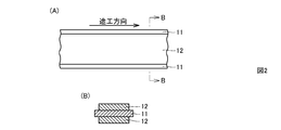
- partial top view (A) which shows the negative electrode material produced in the manufacturing process of Embodiment 1 of the nonaqueous electrolyte secondary battery of this invention, and sectional drawing (B) in the BB line of a partial top view (A) is there.
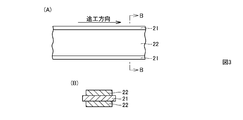
- partial plan view (A) which shows the positive electrode material produced in the manufacturing process of Embodiment 1 of the nonaqueous electrolyte secondary battery of this invention, and sectional drawing (B) in the BB line of a partial top view (A) is there.
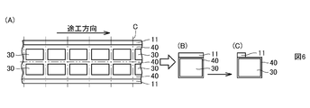
- Partial top view (A) which shows the cutting line of the composite of the negative electrode material, the separator, and the electrical insulation layer produced in the manufacturing process of Embodiment 1 of the nonaqueous electrolyte secondary battery of the present invention, and the negative electrode member after cutting It is a top view (B) (C) which shows two forms of the composite_body
- Partial plan view (A) which shows the cutting line of the positive electrode material produced in the manufacturing process of Embodiment 1 of the nonaqueous electrolyte secondary battery of this invention, and top view (B) which shows two forms of the positive electrode member after a cutting
- FIG. 6 It is a top view (A) (B) which shows two forms of the laminated body of the composite_body
- FIG. 6 shows two forms of the laminated body of the composite_body
- Embodiment 2 of the nonaqueous electrolyte secondary battery as an electrical storage device of this invention.
- the partial plan view (A) which shows the negative electrode material produced in the manufacturing process of Embodiment 2 of the nonaqueous electrolyte secondary battery of this invention
- FIG. 13 It is a top view which shows the cutting location of the composite_body
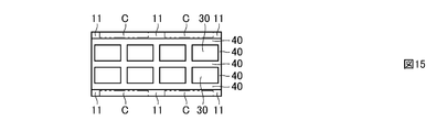
- FIG. 15A is a plan view showing a composite of a negative electrode material, a separator and an electrical insulating layer obtained by cutting different from FIG. 15,
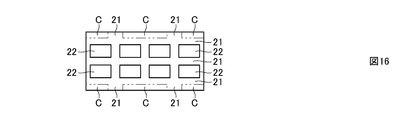
- FIG. 16B is a plan view showing a positive electrode material obtained by cutting different from FIG. It is a top view (C) which shows a cutting line in the laminated body of this composite_body
- Embodiment 1 The basic structure of Embodiment 1 of the nonaqueous electrolyte secondary battery as the electricity storage device of the present invention will be described.
- the electrode structure 100 of a nonaqueous electrolyte secondary battery includes a positive electrode member 20, a negative electrode member 10, and a separator 30 interposed between the positive electrode member 20 and the negative electrode member 10.
- the positive electrode active material layer 22 is fixed to both surfaces of the positive electrode current collector 21.
- negative electrode active material layers 12 are fixed to both surfaces of the negative electrode current collector 11.
- the separator 30 is interposed between the positive electrode active material layer 22 and the negative electrode active material layer 12 and is permeable to the non-aqueous electrolyte.
- the separator 30 is formed of a material including at least an aggregate layer of electrically insulating substance particles in which electrically insulating substance particles are bonded together with a binder.
- the separator 30 is disposed so that the electrical insulating layer 40 faces at least a part of the peripheral side end face of the positive electrode active material layer 22 and is separated from at least a part of the peripheral side end face of the positive electrode active material layer 22. It is fixed on the surface.
- the electrode structure 100 configured as described above is accommodated in a container made of an outer packaging member such as a laminate film.
- the electrical insulating layer 40 is formed in an annular shape, and is disposed at a position surrounding the peripheral side end surface of the positive electrode active material layer 22 and spaced from the peripheral side end surface of the positive electrode active material layer 22. .
- the fixing form of the separator 30 is not limited, in the first embodiment, the separator 30 is fixed to the surface of the negative electrode active material layer 12.
- the positive electrode current collector 21 has a smaller planar area than the negative electrode current collector 11.
- the positive electrode active material layer 22 only needs to be fixed to at least one surface of the positive electrode current collector 21, and the negative electrode active material layer 12 only needs to be fixed to at least one surface of the negative electrode current collector 11.
- Embodiment 1 although the electrode structure 100 which consists of the laminated body of the positive electrode member 20, the separator 30, and the negative electrode member 10 was shown as basic structure, the some positive electrode member 20 and the some negative electrode member 10 are interposed via the separator 30.
- the present invention can also be applied to a laminate in which are alternately laminated.
- the electrical insulating layer 40 becomes the positive electrode active material. It contacts at least a part of the peripheral end surface of the layer 22 and serves as a stopper for the movement of the positive electrode member 20. For this reason, it can prevent that a part of positive electrode moves to the position which does not oppose a negative electrode. In other words, it is possible to prevent the displacement of the positive electrode member 20 during the manufacture of the nonaqueous electrolyte secondary battery.
- the annular electrical insulating layer 40 surrounds the peripheral side end face of the positive electrode active material layer 22, in the manufacturing process of the nonaqueous electrolyte secondary battery, the positive electrode member 20, the separator 30, and the negative electrode member 10 are used.
- the electrical insulating layer 40 comes into contact with the peripheral end surface of the positive electrode active material layer 22 and acts as a stopper for the movement of the positive electrode member 20. For this reason, it can prevent more reliably that a part of positive electrode moves to the position which does not oppose a negative electrode. That is, it is possible to more reliably prevent the displacement of the positive electrode member 20 during the manufacture of the nonaqueous electrolyte secondary battery.
- the first embodiment it is possible to prevent the circumferential end face of the positive electrode current collector 21 from coming into contact with the negative electrode current collector 11 by the annular electric insulating layer 40 fixed to the surface of the separator 30. As a result, an internal short circuit can be prevented.
- the thickness of the electrical insulating layer 40 is preferably equal to or less than the thickness of the positive electrode active material layer 22.
- the thickness of the separator 30 is preferably 0.1 ⁇ m or more and 30 ⁇ m or less, and the thickness of the electrical insulating layer 40 is preferably 0.1 ⁇ m or more and 30 ⁇ m or less.
- the electric insulating layer 40 may be made of an electric insulating material different from that of the separator 30, but is preferably made of the same electric insulating material as that of the separator 30.
- an electrically insulating material such as an inorganic material such as silica or alumina, or a mixture thereof can be used.
- an organic insulating material such as polyvinylidene fluoride, organic materials such as olefins such as polyethylene and polypropylene, inorganic materials such as silica and alumina, or a mixture thereof can be used.
- the separator 30 and the electrical insulating layer 40 are formed by applying and drying a material containing particles of the electrical insulating material and a binder.
- the positive electrode current collector 21 and the negative electrode current collector 11 aluminum or copper can be used as a material of the positive electrode current collector 21 and the negative electrode current collector 11.
- aluminum or copper can be used as a material of the positive electrode current collector 21 and the negative electrode current collector 11.
- an aluminum foil is used for the positive electrode current collector 21, and a copper foil is used for the negative electrode current collector 11. Is preferred.
- the separator 30 is fixed to the surface of the negative electrode active material layer 12, it is possible to more reliably prevent the displacement of the positive electrode member 20 with respect to the negative electrode member 10 during the manufacture of the nonaqueous electrolyte secondary battery.
- the electrode structure 100 is generally manufactured as follows. First, the positive electrode member 20 is produced by fixing the positive electrode active material layer 22 to at least one surface of the positive electrode current collector 21. On the other hand, the negative electrode active material layer 12 is fixed to at least one surface of the negative electrode current collector 11 to produce the negative electrode member 10. Next, a separator 30 including an aggregate layer of electrically insulating material particles is fixed to the surface of the negative electrode active material layer 12 of the negative electrode member 10. Then, the electrical insulating layer 40 is fixed to a part of the surface of the separator 30.
- the electrical insulating layer 40 is disposed so as to face at least a part of the peripheral end face of the positive electrode active material layer 22 and be separated from at least a part of the peripheral end face of the positive electrode active material layer 22.
- the positive electrode member 20 is disposed on the surface of the separator 30.
- Embodiment 1 comprising a laminate in which a plurality of positive electrode members 20 and a plurality of negative electrode members 10 are alternately laminated with separators 30 interposed therebetween will be described. This will be described below.
- the negative electrode active material is applied in the direction indicated by the arrow on both sides of the central region in the width direction, which is a partial surface of the strip-shaped negative electrode current collector 11 made of copper foil, and dried. By doing so, the negative electrode active material layer 12 is fixed. In this way, a negative electrode material is produced.
- a positive electrode active material is applied in a direction indicated by an arrow on both sides of a central region in the width direction, which is a partial surface of a strip-shaped positive electrode current collector 21 made of aluminum foil, and dried. By doing so, the positive electrode active material layer 22 is fixed. In this way, a positive electrode material is produced.
- a grid-like electric insulating layer 40 is fixed by applying a material containing electric insulating substance particles and a binder on the surface of the separator 30 and drying it. .
- a composite of the negative electrode material, the separator 30 and the electrical insulating layer 40 is produced.
- the composite of the negative electrode material obtained above, the separator 30 and the electrical insulating layer 40 is cut according to the cutting line C as shown in FIG. Then, a composite of the negative electrode member for the double-sided lead tab, the separator 30 and the electrical insulating layer 40, which is used in a form in which the positive electrode and negative electrode lead tabs are disposed on both sides of the electrode structure, respectively. Further, by cutting a part of the negative electrode current collector 11, as shown in FIG. 6C, the negative electrode for the one-side lead tab used in the form in which the positive and negative lead tabs are arranged on one side of the electrode structure. A composite of the member, the separator 30 and the electrical insulating layer 40 can be produced.
- the positive electrode material obtained above is cut according to the cutting line C as shown in FIG. 7 (A), so that a positive electrode and a negative electrode are formed on both sides of the electrode structure as shown in FIG. 7 (B).
- the positive electrode member for both-side lead tabs used in the form in which the lead tabs are arranged is prepared. Further, by cutting a part of the positive electrode current collector 21, as shown in FIG. 7C, the positive electrode for the one-side lead tab used in the form in which the positive and negative lead tabs are arranged on one side of the electrode structure. A member can be produced.
- an electrode structure 200 composed of a laminate of the positive electrode member 20, the separator 30 and the negative electrode member 10 as shown in FIGS. make it.
- FIG. 8A shows an electrode structure for both-side lead tabs
- FIG. 8B shows an electrode structure for one-side lead tabs.
- the negative electrode lead tab 13 and the positive electrode lead tab are respectively shown in FIG. 23 is attached.
- FIG. 9 a laminated body of the separator 30, the negative electrode member 10, the separator 30, the positive electrode member 20, the separator 30, the positive electrode member 10, and the separator 30 is shown as a part of the laminated body constituting the electrode structure.
- Protective layers 50 made of aluminum foil are disposed on the outermost layers on both sides of the laminate.
- the protective layer 50 serves to protect the electrical insulating layer 40 disposed around the protective layer 50.
- the electrical insulating layer 40 protrudes outward, so that there is a problem that the electrical insulating layer 40 is easily damaged when contacting the inner wall surface of an outer packaging member such as a laminate film. Therefore, the above problem can be solved by disposing the protective layer 50.
- a material of the protective layer 50 a copper foil may be used.
- Embodiment 2 The basic structure of Embodiment 2 of the nonaqueous electrolyte secondary battery as the electricity storage device of the present invention will be described.
- the electrode structure 300 of the nonaqueous electrolyte secondary battery includes a positive electrode member 20, a negative electrode member 10, and a separator 30 interposed between the positive electrode member 20 and the negative electrode member 10.
- the second embodiment has the same structure as that of the first embodiment except that the positive electrode current collector 21 has substantially the same plane area as the negative electrode current collector 11. Since the positive electrode current collector 21 has substantially the same plane area as the negative electrode current collector 11, the productivity of the nonaqueous electrolyte secondary battery can be improved. Also in the second embodiment, it is possible to obtain the same effect as that of the first embodiment described above.
- the general manufacturing method of the electrode structure 300 is the same as the manufacturing method of the electrode structure 100 described above.
- the electrode structure according to the second embodiment which includes a laminate in which a plurality of positive electrode members 20 and a plurality of negative electrode members 10 are alternately laminated with separators 30 interposed therebetween, will be described. This will be described below.
- a negative electrode active material is applied in the direction indicated by the arrow on both sides of a central region in the width direction, which is a partial surface of a strip-shaped negative electrode current collector 11 made of copper foil, and dried. By doing so, the negative electrode active material layer 12 is fixed. In this way, a negative electrode material is produced.
- a positive electrode active material having a plurality of island-like patterns in the direction indicated by arrows on both surfaces of a central region in the width direction, which is a partial surface of a strip-shaped positive electrode current collector 21 made of aluminum foil. Is applied and dried to fix the positive electrode active material layer 22. In this way, a positive electrode material is produced.
- the composite of the negative electrode material obtained above, the separator 30 and the electrical insulating layer 40 is cut according to the cutting line C as shown in FIG. By this cutting, a composite of the negative electrode material, the separator 30 and the electrical insulating layer 40 is obtained in the shape shown in FIG. Furthermore, the composite body having the shape shown in FIG. 17A is obtained by cutting the portion C shown in FIG.
- the positive electrode material obtained above is cut according to the cutting line C as shown in FIG. By this cutting, a positive electrode material having the shape shown in FIG. 16 is obtained. Furthermore, the positive electrode material having the shape shown in FIG. 17B is obtained by cutting the portion C shown in FIG.
- an electrode structure material composed of a laminate of the positive electrode material, the separator 30 and the negative electrode material is produced as shown in FIG. .
- the electrode structure material is cut according to the cutting line C as shown in FIG.
- an electrode structure 400 composed of a laminate of the positive electrode member 20, the separator 30 and the negative electrode member 10 is produced.
- the electrode structure for one side lead tabs to which the negative electrode lead tab 13 and the positive electrode lead tab 23 were attached can be obtained.
- protective layers 50 made of aluminum foil are disposed on the outermost layers on both sides of the laminate.
- the composite of the shape shown in FIGS. 17A and 17B is not cut and the positive electrode material, but the composite of the shape shown in FIG. 20A and the positive electrode of the shape shown in FIG. Materials can also be obtained.
- the portion C 0 in the central region of the complex is cut out.
- an electrode structure material composed of a laminate of the positive electrode material, the separator 30 and the negative electrode material is produced as shown in FIG. .
- the electrode structural material is cut according to the cutting line C as shown in FIG. Thereby, as shown in FIG. 21, an electrode structure composed of a laminate of the positive electrode member 20, the separator 30, and the negative electrode member 10 is produced.
- the electrode structure for both-sides lead tabs to which the negative electrode lead tab 13 and the positive electrode lead tab 23 were attached can be obtained.
- the positive electrode member 20 is formed by forming the positive electrode active material layer 22 containing the positive electrode active material on both surfaces of the positive electrode current collector 21 except for the end of the positive electrode current collector 21. Composed.
- the negative electrode member 10 is configured by forming negative electrode active material layers 12 including a negative electrode active material on both surfaces of the negative electrode current collector 11 except for an end portion of the negative electrode current collector 11.
- the positive electrode member 20 includes a positive electrode mixture slurry obtained by kneading a positive electrode active material, a binder, and, if necessary, a conductive agent in an organic solvent, on both surfaces of the positive electrode current collector 21 made of aluminum foil.
- the positive electrode active material layer 22 is formed on both surfaces of the positive electrode current collector 21 by being uniformly coated and dried.
- the positive electrode active materials include lithium cobalt oxide composite oxide, lithium manganate composite oxide, lithium nickelate composite oxide, lithium-nickel-manganese-cobalt composite oxide, lithium -Manganese-nickel composite oxide, lithium-manganese-cobalt composite oxide, lithium-nickel-cobalt composite oxide, and the like can be used.
- the positive electrode active material may be a mixture of the above materials.
- LiM x O 2 in the chemical formula, M represents one or more transition metals, x represents a charge / discharge state of the battery, and is usually 0.05 or more as a positive electrode active material of a non-aqueous electrolyte secondary battery.
- lithium composite oxide mainly composed of 1.10 or less.
- transition metal M Co, Ni, Mn and the like are preferable.
- These lithium composite oxides can generate a high voltage and become a positive electrode active material having an excellent energy density.
- the positive electrode active material may be a lithium-containing phosphate compound having an olivine type structure such as lithium iron phosphate represented by LiFePO 4 . If it has an olivine type structure, in the lithium iron phosphate represented by LiFePO 4 , a part of Fe is replaced with Al, Ti, V, Cr, Mn, Co, Ni, Zr, Nb, etc. Also good. A part of P may be replaced with B, Si, or the like.
- binder contained in the positive electrode mixture a known binder that is usually used in a positive electrode mixture of a nonaqueous electrolyte secondary battery can be used.
- a known additive such as a conductive agent and an oxide can be added to.
- Carbon materials such as furnace black and acetylene black are used as the conductive agent contained in the positive electrode mixture.
- a binder for binding the positive electrode active material and the conductive agent polyvinylidene fluoride (PVDF), polyamideimide (PAI), polyacrylonitrile (PAN), polyethylene (PE), polypropylene (PP), polytetrafluoro Ethylene (PTFE) or fluorine-based latex is used.
- a negative electrode slurry obtained by kneading a negative electrode active material, a binder, and, if necessary, a conductive agent in an organic solvent is uniformly formed on both surfaces of the negative electrode current collector 11 made of copper foil.
- the negative electrode active material layer 12 is formed on both surfaces of the negative electrode current collector 11 by coating and drying.
- carbon materials such as non-graphitizable carbon materials, graphitizable carbon materials (soft carbon), and graphite-based carbon materials can be used as the negative electrode active material.
- carbon materials such as pyrolytic carbons, cokes, graphites, glassy carbon fibers, organic polymer compound fired bodies, carbon fibers, and activated carbon can be used.
- the cokes include pitch coke, needle coke, and petroleum coke.
- said organic polymer compound fired body means what carbonized by baking a phenol resin, furan resin, etc. at a suitable temperature.
- materials that can be doped or dedoped with lithium include polymers such as polyacetylene and polypyrrole, Sn oxides such as SnO 2 , Sn alloys such as Sn 5 Cu 6 , and SiMg 2.
- An oxide such as an alloy or Li 4 Ti 5 O 12 (lithium titanate) can also be used.
- a binder contained in said negative electrode compound material the well-known binder used normally for the negative electrode compound material of a nonaqueous electrolyte secondary battery can be used, Said negative electrode compound material A known additive such as a conductive agent and an oxide can be added to.
- a known additive such as a conductive agent and an oxide can be added to.
- the binder for binding the negative electrode active material polyvinylidene fluoride, polyacrylonitrile, polyamideimide, polyacrylonitrile, polyethylene, polypropylene or polytetrafluoroethylene is used, or a latex binder such as styrene butadiene rubber and the like. A mixture of thickeners such as carboxymethylcellulose is used.
- the nonaqueous electrolytic solution is prepared by dissolving the supporting electrolyte in a nonaqueous solvent.
- a nonaqueous electrolyte for example, a solution obtained by dissolving LiPF 6 in a non-aqueous solvent at a concentration of 1.0 mol / L is used.
- supporting electrolytes other than LiPF 6 include lithium salts such as LiBF 4 , LiAsF 6 , LiClO 4 , LiCF 3 SO 3 , LiN (SO 2 CF 3 ) 2 , LiC (SO 2 CF 3 ) 3 , LiAlCl 4 , and LiSiF 6. Can be mentioned.
- LiPF 6 and LiBF 4 are particularly preferably used as the supporting electrolyte from the viewpoint of oxidation stability.
- a supporting electrolyte is preferably used by being dissolved in a nonaqueous solvent at a concentration of 0.1 mol / L to 3.0 mol / L, and at a concentration of 0.5 mol / L to 2.0 mol / L. More preferably, it is used after being dissolved.
- the non-aqueous solvent include cyclic carbonates such as ethylene carbonate (EC) and propylene carbonate (PC), dimethyl carbonate (DMC), ethyl methyl carbonate (EMC), and diethyl carbonate (DEC), which are low viscosity solvents. And a lower chain carbonate of the above are used.
- the present invention is applied to a non-aqueous electrolyte secondary battery as an example of an electricity storage device, but a container of an outer packaging member such as a laminate film is used to accommodate at least an electrode structure.
- the present invention can be applied to any power storage device.
- the present invention can be applied to an electric double layer capacitor in addition to a non-aqueous electrolyte secondary battery.
- the outer packaging member is not limited to a flexible member made of a laminate film having a three-layer structure.
- the present invention it is possible to prevent the displacement of the positive electrode during the manufacture of the electricity storage device, so the present invention improves the reliability of electricity storage devices such as non-aqueous electrolyte secondary batteries and electric double layer capacitors. Can contribute.
Landscapes
- Engineering & Computer Science (AREA)
- Power Engineering (AREA)
- Chemical & Material Sciences (AREA)
- Chemical Kinetics & Catalysis (AREA)
- Electrochemistry (AREA)
- General Chemical & Material Sciences (AREA)
- Microelectronics & Electronic Packaging (AREA)
- Manufacturing & Machinery (AREA)
- Secondary Cells (AREA)
- Battery Electrode And Active Subsutance (AREA)
- Electric Double-Layer Capacitors Or The Like (AREA)
- Cell Separators (AREA)
Abstract
蓄電デバイスの製造時に正極の位置ずれを防止することが可能な蓄電デバイスおよびその製造方法を提供する。非水電解質二次電池の電極構造体(100)は、正極集電体(21)の少なくとも一方の表面に正極活物質層(22)が固着された正極部材(20)と、正極活物質層(22)に対向するように負極集電体(11)の少なくとも一方の表面に負極活物質層(12)が固着された負極部材(10)と、正極活物質層(22)と負極活物質層(12)との間に介在し、電気絶縁性物質粒子の集合体層を含むセパレータ(30)と、正極活物質層(22)の周側端面の少なくとも一部に対向し、かつ、正極活物質層(22)の周側端面の少なくとも一部から離隔した位置に配置されるようにセパレータ(30)の表面に固着された電気絶縁層(40)とから構成される。
Description
本発明は、一般的には蓄電デバイスおよびその製造方法に関し、特定的には、非水電解質二次電池、電気二重層キャパシタ等の蓄電要素を備えた蓄電デバイスおよびその製造方法に関するものである。
従来から、たとえば、非水電解質二次電池等の蓄電デバイスに関しては、多様な用途の拡大に伴って、軽量化、薄型化、形状の自由度等の要求が高まっている。
そこで、たとえば、平板状の電極板積層体を可撓性容器内に備え、電池形状の自由度が比較的高い薄型の非水電解質二次電池の構造とその製造方法が、国際公開第WO98/38688号(以下、特許文献1という)に開示されている。
特許文献1に開示された非水電解質二次電池は、集電体の少なくとも一方の面に活物質層が固定された正極および負極と、両極の活物質層間に介装された電解液透過性を有するセパレータとを少なくとも有する電極板積層体を容器内に備え、この容器内に非水系電解液が封入されたものである。正極活物質層および負極活物質層の少なくとも一方の端面は、その少なくとも一部が絶縁性物質粒子集合体層でコーティングされている。正極活物質層は、電池層として対をなす負極活物質層からはみ出さない大きさに形成されている。セパレータは、絶縁性物質粒子同士がバインダーで結合された絶縁性物質粒子集合体層であって、正極および負極の少なくともいずれか一方に固定され、少なくとも負極と対向する正極活物質層の表面全体を覆うように、かつ集電体の端面からはみ出さないように配置されている。
特許文献1に開示されているように非水電解質二次電池等の蓄電デバイスでは、正極の全部が負極に対向するように、正極の表面積よりも負極の表面積が大きく設定されている。このため、通常の電極板積層体では、充電時にリチウムイオンの受取先である負極が、リチウムイオンを放出する正極を充分に覆うように配置されている。この配置により、充電時にリチウムイオンが正極から負極に移動する際に、リチウムイオンが溢れることなく、負極のサイトに充填される。
しかしながら、蓄電デバイスの製造時に、正極の一部が負極に対向しないように配置されることが起こり得る。すなわち、正極の位置ずれが生じる場合がある。このとき、充電時にリチウムイオンの受取先である負極の一部に、リチウムイオンを放出する正極を覆っていない部分が存在する。この配置により、充電時にリチウムイオンが正極から負極に移動する際に、負極と対向していない正極の部分から放出されるリチウムイオンの行き先が負極の端部に集中することになる。その結果、リチウムイオンの受取先である負極においてリチウムイオンが飽和することになり、負極のサイトに充填できないリチウムイオンが、リチウム金属として負極の表面に析出するという問題がある。
また、正極の位置ずれが生じると、正極集電体と負極集電体とが接触することにより、内部短絡が生じる場合がある。
そこで、本発明の目的は、蓄電デバイスの製造時に正極の位置ずれを防止することが可能な蓄電デバイスおよびその製造方法を提供することである。
本発明に従った蓄電デバイスは、正極集電体の少なくとも一方の表面に正極活物質層が固着された正極部材と、正極活物質層に対向するように負極集電体の少なくとも一方の表面に負極活物質層が固着された負極部材と、正極活物質層と負極活物質層との間に介在し、電気絶縁性物質粒子の集合体層を含むセパレータと、正極活物質層の周側端面の少なくとも一部に対向し、かつ、正極活物質層の周側端面の少なくとも一部から離隔した位置に配置されるようにセパレータの表面に固着された電気絶縁層とを備える。
本発明の蓄電デバイスでは、蓄電デバイスの製造工程において、正極部材、セパレータおよび負極部材を重ねたときに正極部材が移動しようとすると、電気絶縁層が、正極活物質層の周側端面の少なくとも一部に当接して、正極部材の移動に対してストッパの役割を果たす。このため、正極の一部が負極に対向しない位置に移動することを防止することができる。すなわち、蓄電デバイスの製造時に正極部材の位置ずれを防止することが可能になる。したがって、充電時にリチウムイオンの受取先である負極の一部に、リチウムイオンを放出する正極を覆っていない部分が存在しないようにすることができるので、充電時にリチウムイオンが正極から負極に移動する際に、リチウムイオンが溢れることなく、負極のサイトに充填される。その結果、リチウム金属が負極の表面に析出することを防止することができる。
本発明の蓄電デバイスにおいて、電気絶縁層は、正極活物質層の周側端面を囲み、かつ、正極活物質層の周側端面から離隔した位置に配置されていることが好ましい。
この場合、電気絶縁層が正極活物質層の周側端面を囲んでいるので、蓄電デバイスの製造工程において、正極部材、セパレータおよび負極部材を重ねたときに正極部材が移動しようとすると、電気絶縁層が正極活物質層の周側端面に当接して、正極部材の移動に対してストッパの役割を果たす。このため、正極の一部が負極に対向しない位置に移動することをより確実に防止することができる。すなわち、蓄電デバイスの製造時に正極部材の位置ずれをより確実に防止することが可能になる。したがって、充電時にリチウムイオンの受取先である負極の一部に、リチウムイオンを放出する正極を覆っていない部分が存在することがないので、充電時にリチウムイオンが正極から負極に移動する際に、リチウムイオンが溢れることなく、負極のサイトに充填される。その結果、リチウム金属が負極の表面に析出することをより確実に防止することができる。
また、この場合、セパレータの表面に固着された電気絶縁層によって、正極集電体の周側端面が負極集電体に接触することを防止することができる。その結果、内部短絡を防止することができる。
電気絶縁層の厚みは、正極活物質層の厚み以下であることが好ましい。
また、セパレータの厚みは0.1μm以上30μm以下であり、電気絶縁層の厚みは0.1μm以上30μm以下であることが好ましい。
電気絶縁層は、セパレータと同じ電気絶縁性物質から構成されていることが好ましい。
正極集電体は、負極集電体とほぼ同じ平面積を有することが好ましい。このように構成することにより、蓄電デバイスの生産性を向上させることができる。
セパレータは、負極活物質層の表面に固着されていることが好ましい。このように構成することにより、蓄電デバイスの製造時に正極部材の負極部材に対する位置ずれをより確実に防止することが可能になる。
セパレータを介在して複数の正極部材と複数の負極部材とが交互に積層されていることが好ましい。
本発明に従った蓄電デバイスの製造方法は、以下のステップを備える。
(A)正極集電体の少なくとも一方の表面に正極活物質層を固着することによって正極部材を作製するステップ
(B)負極集電体の少なくとも一方の表面に負極活物質層を固着することによって負極部材を作製するステップ
(C)負極部材の負極活物質層の表面に、電気絶縁性物質粒子の集合体層を含むセパレータを固着するステップ
(D)セパレータの一部の表面に電気絶縁層を固着するステップ
(E)電気絶縁層が、正極活物質層の周側端面の少なくとも一部に対向し、かつ、正極活物質層の周側端面の少なくとも一部から離隔した位置に配置されるように、セパレータの表面に正極部材を配置するステップ
本発明によれば、蓄電デバイスの製造時に正極の位置ずれを防止することが可能になる。
以下、本発明の実施の形態について、蓄電デバイスの一例として非水電解質二次電池を挙げて説明する。
(実施形態1)
本発明の蓄電デバイスとしての非水電解質二次電池の実施形態1の基本構造を説明する。
本発明の蓄電デバイスとしての非水電解質二次電池の実施形態1の基本構造を説明する。
図1に示すように、非水電解質二次電池の電極構造体100は、正極部材20と、負極部材10と、正極部材20と負極部材10との間に介在するセパレータ30とを備える。正極部材20においては、正極集電体21の両面に正極活物質層22が固着されている。負極部材10においては、負極集電体11の両面に負極活物質層12が固着されている。セパレータ30は、正極活物質層22と負極活物質層12との間に介在し、非水電解液に対して透過性を有する。また、セパレータ30は、電気絶縁性物質粒子同士が結着剤で結合された電気絶縁性物質粒子の集合体層を少なくとも含む材料から形成される。電気絶縁層40が、正極活物質層22の周側端面の少なくとも一部に対向し、かつ、正極活物質層22の周側端面の少なくとも一部から離隔した位置に配置されるようにセパレータ30の表面に固着されている。以上のように構成された電極構造体100は、ラミネートフィルム等の外包部材からなる容器内に収容される。
実施形態1では、電気絶縁層40は、環状に形成されており、正極活物質層22の周側端面を囲み、かつ、正極活物質層22の周側端面から離隔した位置に配置されている。また、セパレータ30の固着形態は限定されないが、実施形態1では、セパレータ30は負極活物質層12の表面に固着されている。また、実施形態1では、正極集電体21は、負極集電体11よりも小さな平面積を有する.なお、正極活物質層22は正極集電体21の少なくとも一方の表面に固着されていればよく、負極活物質層12は負極集電体11の少なくとも一方の表面に固着されていればよい。実施形態1では、基本構造として正極部材20、セパレータ30および負極部材10の積層体からなる電極構造体100を示したが、セパレータ30を介在して複数の正極部材20と複数の負極部材10とが交互に積層された積層体にも本発明は適用され得る。
電極構造体100では、非水電解質二次電池の製造工程において、正極部材20、セパレータ30および負極部材10を重ねたときに正極部材20が移動しようとすると、電気絶縁層40が、正極活物質層22の周側端面の少なくとも一部に当接して、正極部材20の移動に対してストッパの役割を果たす。このため、正極の一部が負極に対向しない位置に移動することを防止することができる。すなわち、非水電解質二次電池の製造時に正極部材20の位置ずれを防止することが可能になる。したがって、充電時にリチウムイオンの受取先である負極の一部に、リチウムイオンを放出する正極を覆っていない部分が存在しないようにすることができるので、充電時にリチウムイオンが正極から負極に移動する際に、リチウムイオンが溢れることなく、負極のサイトに充填される。その結果、リチウム金属が負極の表面に析出することを防止することができる。
さらに、実施形態1では、環状の電気絶縁層40が正極活物質層22の周側端面を囲んでいるので、非水電解質二次電池の製造工程において、正極部材20、セパレータ30および負極部材10を重ねたときに正極部材20が移動しようとすると、電気絶縁層40が正極活物質層22の周側端面に当接して、正極部材20の移動に対してストッパの役割を果たす。このため、正極の一部が負極に対向しない位置に移動することをより確実に防止することができる。すなわち、非水電解質二次電池の製造時に正極部材20の位置ずれをより確実に防止することが可能になる。したがって、充電時にリチウムイオンの受取先である負極の一部に、リチウムイオンを放出する正極を覆っていない部分が存在することがないので、充電時にリチウムイオンが正極から負極に移動する際に、リチウムイオンが溢れることなく、負極のサイトに充填される。その結果、リチウム金属が負極の表面に析出することをより確実に防止することができる。
また、実施形態1では、セパレータ30の表面に固着された環状の電気絶縁層40によって、正極集電体21の周側端面が負極集電体11に接触することを防止することができる。その結果、内部短絡を防止することができる。
電気絶縁層40の厚みは、正極活物質層22の厚み以下であることが好ましい。また、セパレータ30の厚みは0.1μm以上30μm以下であり、電気絶縁層40の厚みは0.1μm以上30μm以下であることが好ましい。電気絶縁層40は、セパレータ30と異なる電気絶縁性物質から構成されてもよいが、セパレータ30と同じ電気絶縁性物質から構成されていることが好ましい。たとえば、セパレータ30の材料としては、シリカ、アルミナ等の無機物、または、これらの混合物等の電気絶縁性物質を用いることができる。電気絶縁層40の材料としては、ポリフッ化ビニリデン、ポリエチレン、ポリプロピレン等のオレフィン等の有機物、シリカ、アルミナ等の無機物、または、これらの混合物等の電気絶縁性物質を用いることができる。なお、セパレータ30と電気絶縁層40は、上記の電気絶縁性物質の粒子と結着剤を含む材料を塗工し、乾燥させることにより、形成される。
なお、正極集電体21と負極集電体11の材料としては、アルミニウムまたは銅を用いることができるが、正極集電体21にはアルミニウム箔、負極集電体11には銅箔を用いることが好ましい。
セパレータ30は、負極活物質層12の表面に固着されているので、非水電解質二次電池の製造時に正極部材20の負極部材10に対する位置ずれをより確実に防止することが可能になる。
電極構造体100は、概略、次のようにして製造される。まず、正極集電体21の少なくとも一方の表面に正極活物質層22を固着することによって正極部材20を作製する。一方、負極集電体11の少なくとも一方の表面に負極活物質層12を固着することによって負極部材10を作製する。次に、負極部材10の負極活物質層12の表面に、電気絶縁性物質粒子の集合体層を含むセパレータ30を固着する。そして、セパレータ30の一部の表面に電気絶縁層40を固着する。最後に、電気絶縁層40が、正極活物質層22の周側端面の少なくとも一部に対向し、かつ、正極活物質層22の周側端面の少なくとも一部から離隔した位置に配置されるように、セパレータ30の表面に正極部材20を配置する。
次に、セパレータ30を介在して複数の正極部材20と複数の負極部材10とが交互に積層された積層体からなる実施形態1の電極構造体の製造方法について、図2~図9を参照して、以下に説明する。
図2に示すように、銅箔からなる帯状の負極集電体11の一部表面である幅方向の中央部領域の両面の上に、矢印で示す方向に負極活物質を塗工し、乾燥することにより、負極活物質層12を固着させる。このようにして負極材料を作製する。
図3に示すように、アルミニウム箔からなる帯状の正極集電体21の一部表面である幅方向の中央部領域の両面の上に、矢印で示す方向に正極活物質を塗工し、乾燥させることにより、正極活物質層22を固着させる。このようにして正極材料を作製する。
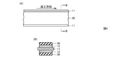
次に、図4に示すように、上記で得られた負極材料の負極活物質層12の表面の上に、電気絶縁性物質粒子と結着剤とを含む材料を塗工し、乾燥させることにより、セパレータ30を固着させる。
その後、図5に示すように、セパレータ30の表面の上に、電気絶縁性物質粒子と結着剤とを含む材料を塗工し、乾燥させることにより、格子状の電気絶縁層40を固着させる。このようにして、負極材料とセパレータ30と電気絶縁層40の複合体を作製する。
上記で得られた負極材料とセパレータ30と電気絶縁層40の複合体を、図6の(A)に示すように、切断線Cに従って切断することにより、図6の(B)に示すように、電極構造体の両側にそれぞれ正極と負極のリードタブが配置される形態に用いられる両側リードタブ用の負極部材とセパレータ30と電気絶縁層40の複合体を作製する。さらに、負極集電体11の一部を切断することにより、図6の(C)に示すように、電極構造体の片側に正負極のリードタブが配置される形態に用いられる片側リードタブ用の負極部材とセパレータ30と電気絶縁層40の複合体を作製することができる。
上記で得られた正極材料を、図7の(A)に示すように、切断線Cに従って切断することにより、図7の(B)に示すように、電極構造体の両側にそれぞれ正極と負極のリードタブが配置される形態に用いられる両側リードタブ用の正極部材を作製する。さらに、正極集電体21の一部を切断することにより、図7の(C)に示すように、電極構造体の片側に正負極のリードタブが配置される形態に用いられる片側リードタブ用の正極部材を作製することができる。
上記で得られた複数の正極部材と複合体を交互に積み重ねることにより、図8と図9に示すように正極部材20、セパレータ30および負極部材10の積層体から構成される電極構造体200を作製する。
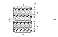
なお、図8の(A)には両側リードタブ用の電極構造体が示され、図8の(B)には片側リードタブ用の電極構造体が示されており、それぞれ、負極リードタブ13と正極リードタブ23が取り付けられている。図9では、電極構造体を構成する積層体の一部として、セパレータ30、負極部材10、セパレータ30、正極部材20、セパレータ30、正極部材10、セパレータ30の積層体が示されている。
積層体の両側の最外層には、アルミニウム箔からなる保護層50が配置されている。保護層50は、保護層50の周囲に配置される電気絶縁層40を保護する役割をする。保護層50がない場合、電気絶縁層40が外側に突出しているので、ラミネートフィルム等の外包部材の内壁面に接触した際に電気絶縁層40が損傷しやすいという問題がある。したがって、保護層50を配置することによって、上記の問題を解消することができる。保護層50の材料としては、銅箔を用いてもよい。
(実施形態2)
本発明の蓄電デバイスとしての非水電解質二次電池の実施形態2の基本構造を説明する。
本発明の蓄電デバイスとしての非水電解質二次電池の実施形態2の基本構造を説明する。
図10に示すように、非水電解質二次電池の電極構造体300は、正極部材20と、負極部材10と、正極部材20と負極部材10との間に介在するセパレータ30とを備える。実施形態2は、正極集電体21が負極集電体11とほぼ同じ平面積を有する点を除いては、実施形態1と同じ構造である。正極集電体21が負極集電体11とほぼ同じ平面積を有するので、非水電解質二次電池の生産性を向上させることができる。実施形態2においても、上述した実施形態1と同様の作用効果を得ることができる。
電極構造体300の概略の製造方法は、上述した電極構造体100の製造方法と同様である。
次に、セパレータ30を介在して複数の正極部材20と複数の負極部材10とが交互に積層された積層体からなる実施形態2の電極構造体の製造方法について、図11~図21を参照して、以下に説明する。
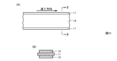
図11に示すように、銅箔からなる帯状の負極集電体11の一部表面である幅方向の中央部領域の両面の上に、矢印で示す方向に負極活物質を塗工し、乾燥することにより、負極活物質層12を固着させる。このようにして負極材料を作製する。
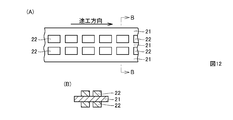
図12に示すように、アルミニウム箔からなる帯状の正極集電体21の一部表面である幅方向の中央部領域の両面の上に、矢印で示す方向に複数の島状パターンで正極活物質を塗工し、乾燥させることにより、正極活物質層22を固着させる。このようにして正極材料を作製する。
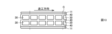
次に、実施形態1と同様にして、図13に示すように、負極材料とセパレータ30と電気絶縁層40の複合体を作製する。
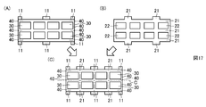
上記で得られた負極材料とセパレータ30と電気絶縁層40の複合体を、図13に示すように、切断線Cに従って切断する。この切断によって、図15に示す形状で、負極材料とセパレータ30と電気絶縁層40の複合体を得る。さらに、図15に示す箇所Cを切断することにより、図17の(A)で示す形状の複合体を得る。
上記で得られた正極材料を、図14に示すように、切断線Cに従って切断する。この切断によって、図16に示す形状の正極材料を得る。さらに、図16に示す箇所Cを切断することにより、図17の(B)で示す形状の正極材料を得る。
上記で得られた複数の正極材料と複合体を交互に積み重ねることにより、図17の(C)に示すように正極材料、セパレータ30および負極材料の積層体から構成される電極構造材料を作製する。
そして、上記の電極構造材料を、図17の(C)に示すように、切断線Cに従って切断する。これにより、図18と図19に示すように、正極部材20、セパレータ30および負極部材10の積層体から構成される電極構造体400を作製する。なお、図18に示すように、負極リードタブ13と正極リードタブ23が取り付けられた片側リードタブ用の電極構造体を得ることができる。実施形態1の電極構造体200と同様に、積層体の両側の最外層には、アルミニウム箔からなる保護層50が配置されている。
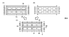
図17の(A)と(B)で示す形状の複合体と正極材料ではなく、切断により、図20の(A)で示す形状の複合体と、図20の(B)で示す形状の正極材料を得ることもできる。この場合、図20の(A)で示すように、複合体の中央領域の箇所C0を切り抜く。
上記で得られた複数の正極材料と複合体を交互に積み重ねることにより、図20の(C)に示すように正極材料、セパレータ30および負極材料の積層体から構成される電極構造材料を作製する。
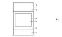
そして、上記の電極構造材料を、図20の(C)に示すように、切断線Cに従って切断する。これにより、図21に示すように、正極部材20、セパレータ30および負極部材10の積層体から構成される電極構造体を作製する。なお、図21に示すように、負極リードタブ13と正極リードタブ23が取り付けられた両側リードタブ用の電極構造体を得ることができる。
なお、上記の実施形態では、正極部材20は、正極集電体21の端部を除いて、正極活物質を含む正極活物質層22が正極集電体21の両面上に形成されることによって構成される。負極部材10は、負極集電体11の端部を除いて、負極活物質を含む負極活物質層12が負極集電体11の両面上に形成されることによって構成される。
たとえば、正極部材20は、正極活物質と結着剤と必要に応じて導電剤とを有機溶媒中で混錬してなる正極合材スラリーを、アルミニウム箔からなる正極集電体21の両面上に均一に塗工し、乾燥させて、正極活物質層22を正極集電体21の両面上に形成することにより作製される。
非水電解質二次電池を構成する場合、正極活物質としては、コバルト酸リチウム複合酸化物、マンガン酸リチウム複合酸化物、ニッケル酸リチウム複合酸化物、リチウム‐ニッケル‐マンガン‐コバルト複合酸化物、リチウム‐マンガン‐ニッケル複合酸化物、リチウム‐マンガン‐コバルト複合酸化物、リチウム‐ニッケル‐コバルト複合酸化物等を用いることができる。さらに、正極活物質は、上記の材料を混合したものでもよい。具体的には、非水電解液二次電池の正極活物質としてLiMxO2(化学式中、Mは一種以上の遷移金属を表し、xは電池の充放電状態によって異なり、通常0.05以上、1.10以下である)を主体とするリチウム複合酸化物等を使用することができる。このリチウム複合酸化物を構成する遷移金属Mとしては、Co、Ni、Mn等が好ましい。このようなリチウム複合酸化物の具体例としてはLiCoO2、LiNiO2、LiNiyCo1-yO2(化学式中、0<y<1である)、Li1+a(NixMnyCoz)O2-b(化学式中、-0.1<a<0.2、x+y+z=1、-0.1<b<0.1)、LiMn2O4等を挙げることができる。これらのリチウム複合酸化物は、高電圧を発生でき、エネルギー密度が優れた正極活物質となる。正極部材20を作製するために、これらの正極活物質の複数種をあわせて使用してもよい。正極活物質は、LiFePO4で表わされるリン酸鉄リチウム等のオリビン型構造を有するリチウム含有リン酸化合物でもよい。オリビン型構造を有しているのであれば、LiFePO4で表わされるリン酸鉄リチウムにおいて、Feの一部をAl、Ti、V、Cr、Mn、Co、Ni、Zr、Nb等で置換してもよい。また、Pの一部をB、Si等で置換してもよい。
また、上記の正極合材に含有される結着剤としては、通常、非水電解質二次電池の正極合材に用いられている公知の結着剤を用いることができ、上記の正極合材には、導電剤、酸化物等、公知の添加剤を添加することができる。上記の正極合材に含有される導電剤としては、ファーネスブラック、アセチレンブラック等の炭素材料が用いられる。正極活物質と導電剤を結着させるための結着剤としては、ポリフッ化ビニリデン(PVDF)、ポリアミドイミド(PAI)、ポリアクリロニトリル(PAN)、ポリエチレン(PE)、ポリプロピレン(PP)、ポリテトラフルオロエチレン(PTFE)またはフッ素系ラテックスが用いられる。
たとえば、負極部材10は、負極活物質と結着剤と必要に応じて導電剤とを有機溶媒中で混錬してなる負極スラリーを、銅箔からなる負極集電体11の両面上に均一に塗工し、乾燥させて、負極活物質層12を負極集電体11の両面上に形成することにより作製される。
非水電解質二次電池を構成する場合、負極活物質としては、難黒鉛化炭素材料、易黒鉛化炭素材料(ソフトカーボン)、グラファイト系炭素材料等の炭素材料を使用することができる。具体的には、熱分解炭素類、コークス類、黒鉛類、ガラス状炭素繊維、有機高分子化合物焼成体、炭素繊維、活性炭等の炭素材料を使用することができる。上記のコークス類には、ピッチコークス、ニードルコークス、石油コークス等がある。また、上記の有機高分子化合物焼成体とは、フェノール樹脂、フラン樹脂等を適当な温度で焼成して炭素化したものをいう。上述した炭素材料のほか、リチウムをドープ、脱ドープできる材料としては、ポリアセチレン、ポリピロール等の高分子、SnO2等のSn酸化物系、Sn5Cu6等のSn合金系、SiMg2等のSi合金系、Li4Ti5O12(チタン酸リチウム)等の酸化物を使用することもできる。
また、上記の負極合材に含有される結着剤としては、通常、非水電解質二次電池の負極合材に用いられている公知の結着剤を用いることができ、上記の負極合材には、導電剤、酸化物等、公知の添加剤を添加することができる。負極活物質を結着させるための結着剤としては、ポリフッ化ビニリデン、ポリアクリロニトリル、ポリアミドイミド、ポリアクリロニトリル、ポリエチレン、ポリプロピレンまたはポリテトラフルオロエチレンが用いられ、あるいは、スチレンブタジエンラバー等のラテックスバインダーとカルボキシメチルセルロース等の増粘剤の混合物が用いられる。
非水電解液は、支持電解質を非水溶媒に溶解して調製される。非水電解液としては、たとえば、非水溶媒中にLiPF6を1.0mol/Lの濃度で溶解したものが使用される。LiPF6以外の支持電解質としては、LiBF4、LiAsF6、LiClO4、LiCF3SO3、LiN(SO2CF3)2、LiC(SO2CF3)3、LiAlCl4、LiSiF6等のリチウム塩を挙げることができる。これらの中でも、支持電解質として特にLiPF6、LiBF4を用いることが酸化安定性の点から望ましい。このような支持電解質は、非水溶媒中に、0.1mol/L~3.0mol/Lの濃度で溶解されて用いられることが好ましく、0.5mol/L~2.0mol/Lの濃度で溶解されて用いられることがさらに好ましい。上記の非水溶媒としては、エチレンカーボネート(EC)、プロピレンカーボネート(PC)等の環状炭酸エステルに、低粘性溶媒であるジメチルカーボネート(DMC)、エチルメチルカーボネート(EMC)、ジエチルカーボネート(DEC)等の低級鎖状炭酸エステルを加えたものが用いられる。
上記の実施の形態では、本発明を蓄電デバイスの一例として非水電解質二次電池に適用した例について説明したが、少なくとも電極構造体を収容するためにラミネートフィルム等の外包部材の容器を用いた蓄電デバイスであれば、本発明を適用することができ、たとえば、非水電解質二次電池の他に、電気二重層キャパシタ等に本発明を適用することができる。なお、外包部材は、三層構造のラミネートフィルム等からなる可撓性を有するものに限定されない。
今回開示された実施の形態はすべての点で例示であって制限的なものではないと考慮されるべきである。本発明の範囲は以上の実施の形態ではなく、請求の範囲によって示され、請求の範囲と均等の意味および範囲内でのすべての修正と変形を含むものであることが意図される。
本発明によれば、蓄電デバイスの製造時に正極の位置ずれを防止することが可能になるので、本発明は、非水電解質二次電池、電気二重層キャパシタ等の蓄電デバイスの信頼性の向上に寄与することができる。
10:負極部材、11:負極集電体、12:負極活物質層、20:正極部材、21:正極集電体、22:正極活物質層、30:セパレータ、40:電気絶縁層、100,200,300,400:電極構造体。
Claims (9)
- 正極集電体の少なくとも一方の表面に正極活物質層が固着された正極部材と、
前記正極活物質層に対向するように負極集電体の少なくとも一方の表面に負極活物質層が固着された負極部材と、
前記正極活物質層と前記負極活物質層との間に介在し、電気絶縁性物質粒子の集合体層を含むセパレータと、
前記正極活物質層の周側端面の少なくとも一部に対向し、かつ、前記正極活物質層の周側端面の少なくとも一部から離隔した位置に配置されるように前記セパレータの表面に固着された電気絶縁層とを備える、蓄電デバイス。 - 前記電気絶縁層が、前記正極活物質層の周側端面を囲み、かつ、前記正極活物質層の周側端面から離隔した位置に配置されている、請求項1に記載の蓄電デバイス。
- 前記電気絶縁層の厚みが、前記正極活物質層の厚み以下である、請求項1または請求項2のいずれか1項に記載の蓄電デバイス。
- 前記セパレータの厚みが0.1μm以上30μm以下であり、前記電気絶縁層の厚みが0.1μm以上30μm以下である、請求項1から請求項3までのいずれか1項に記載の蓄電デバイス。
- 前記電気絶縁層が、前記セパレータと同じ電気絶縁性物質から構成されている、請求項1から請求項4までのいずれか1項に記載の蓄電デバイス。
- 前記正極集電体が、前記負極集電体とほぼ同じ平面積を有する、請求項1から請求項5までのいずれか1項に記載の蓄電デバイス。
- 前記セパレータが、前記負極活物質層の表面に固着されている、請求項1から請求項6までのいずれか1項に記載の蓄電デバイス。
- 前記セパレータを介在して複数の前記正極部材と複数の前記負極部材とが交互に積層されている、請求項1から請求項7までのいずれか1項に記載の蓄電デバイス。
- 正極集電体の少なくとも一方の表面に正極活物質層を固着することによって正極部材を作製するステップと、
負極集電体の少なくとも一方の表面に負極活物質層を固着することによって負極部材を作製するステップと、
前記負極部材の負極活物質層の表面に、電気絶縁性物質粒子の集合体層を含むセパレータを固着するステップと、
前記セパレータの一部の表面に電気絶縁層を固着するステップと、
前記電気絶縁層が、前記正極活物質層の周側端面の少なくとも一部に対向し、かつ、前記正極活物質層の周側端面の少なくとも一部から離隔した位置に配置されるように、前記セパレータの表面に前記正極部材を配置するステップとを備える、蓄電デバイスの製造方法。
Priority Applications (1)
| Application Number | Priority Date | Filing Date | Title |
|---|---|---|---|
| JP2014551964A JP6149867B2 (ja) | 2012-12-11 | 2013-11-27 | 蓄電デバイスの製造方法 |
Applications Claiming Priority (2)
| Application Number | Priority Date | Filing Date | Title |
|---|---|---|---|
| JP2012-270659 | 2012-12-11 | ||
| JP2012270659 | 2012-12-11 |
Publications (1)
| Publication Number | Publication Date |
|---|---|
| WO2014091925A1 true WO2014091925A1 (ja) | 2014-06-19 |
Family
ID=50934219
Family Applications (1)
| Application Number | Title | Priority Date | Filing Date |
|---|---|---|---|
| PCT/JP2013/081847 Ceased WO2014091925A1 (ja) | 2012-12-11 | 2013-11-27 | 蓄電デバイスおよびその製造方法 |
Country Status (2)
| Country | Link |
|---|---|
| JP (1) | JP6149867B2 (ja) |
| WO (1) | WO2014091925A1 (ja) |
Cited By (3)
| Publication number | Priority date | Publication date | Assignee | Title |
|---|---|---|---|---|
| CN112993378A (zh) * | 2021-03-26 | 2021-06-18 | 天津市捷威动力工业有限公司 | 一种应用于锂二次电池的电极组件 |
| JPWO2021131095A1 (ja) * | 2019-12-27 | 2021-07-01 | ||
| JP2025008515A (ja) * | 2023-07-05 | 2025-01-20 | トヨタ自動車株式会社 | 蓄電セル及び電極体の製造方法 |
Citations (6)
| Publication number | Priority date | Publication date | Assignee | Title |
|---|---|---|---|---|
| JP2001102050A (ja) * | 1999-09-30 | 2001-04-13 | Toyota Motor Corp | 積層型電池・キャパシタ用電極構造体 |
| JP2005190912A (ja) * | 2003-12-26 | 2005-07-14 | Matsushita Electric Ind Co Ltd | リチウム二次電池およびその製造方法 |
| JP2012009210A (ja) * | 2010-06-23 | 2012-01-12 | Mitsubishi Heavy Ind Ltd | 電池 |
| JP2012069283A (ja) * | 2010-09-21 | 2012-04-05 | Nissan Motor Co Ltd | 積層型電池の製造方法および積層型電池用セパレータ |
| JP2012190696A (ja) * | 2011-03-11 | 2012-10-04 | Mitsubishi Heavy Ind Ltd | 電池 |
| JP2012209072A (ja) * | 2011-03-29 | 2012-10-25 | Nec Corp | 電極積層型電池の電極積層体、および該電極積層体の製造方法 |
Family Cites Families (2)
| Publication number | Priority date | Publication date | Assignee | Title |
|---|---|---|---|---|
| JP4003845B2 (ja) * | 1997-04-17 | 2007-11-07 | 日立マクセル株式会社 | 電気二重層キャパシタと電池とのハイブリッド素子 |
| US6277520B1 (en) * | 1999-03-19 | 2001-08-21 | Ntk Powerdex, Inc. | Thin lithium battery with slurry cathode |
-
2013
- 2013-11-27 WO PCT/JP2013/081847 patent/WO2014091925A1/ja not_active Ceased
- 2013-11-27 JP JP2014551964A patent/JP6149867B2/ja active Active
Patent Citations (6)
| Publication number | Priority date | Publication date | Assignee | Title |
|---|---|---|---|---|
| JP2001102050A (ja) * | 1999-09-30 | 2001-04-13 | Toyota Motor Corp | 積層型電池・キャパシタ用電極構造体 |
| JP2005190912A (ja) * | 2003-12-26 | 2005-07-14 | Matsushita Electric Ind Co Ltd | リチウム二次電池およびその製造方法 |
| JP2012009210A (ja) * | 2010-06-23 | 2012-01-12 | Mitsubishi Heavy Ind Ltd | 電池 |
| JP2012069283A (ja) * | 2010-09-21 | 2012-04-05 | Nissan Motor Co Ltd | 積層型電池の製造方法および積層型電池用セパレータ |
| JP2012190696A (ja) * | 2011-03-11 | 2012-10-04 | Mitsubishi Heavy Ind Ltd | 電池 |
| JP2012209072A (ja) * | 2011-03-29 | 2012-10-25 | Nec Corp | 電極積層型電池の電極積層体、および該電極積層体の製造方法 |
Cited By (4)
| Publication number | Priority date | Publication date | Assignee | Title |
|---|---|---|---|---|
| JPWO2021131095A1 (ja) * | 2019-12-27 | 2021-07-01 | ||
| JP7565525B2 (ja) | 2019-12-27 | 2024-10-11 | パナソニックIpマネジメント株式会社 | 電池の製造方法 |
| CN112993378A (zh) * | 2021-03-26 | 2021-06-18 | 天津市捷威动力工业有限公司 | 一种应用于锂二次电池的电极组件 |
| JP2025008515A (ja) * | 2023-07-05 | 2025-01-20 | トヨタ自動車株式会社 | 蓄電セル及び電極体の製造方法 |
Also Published As
| Publication number | Publication date |
|---|---|
| JP6149867B2 (ja) | 2017-06-21 |
| JPWO2014091925A1 (ja) | 2017-01-05 |
Similar Documents
| Publication | Publication Date | Title |
|---|---|---|
| KR101304108B1 (ko) | 각형 전지 | |
| US10270121B2 (en) | Secondary battery | |
| JP5554181B2 (ja) | 非水電解質二次電池 | |
| JP6936670B2 (ja) | リチウムイオン電池用セパレータ | |
| JP7405243B2 (ja) | 集電体、蓄電素子及び蓄電モジュール | |
| WO2018154989A1 (ja) | 二次電池およびその製造方法 | |
| WO2017110684A1 (ja) | 二次電池とその製造方法 | |
| JP2009187675A (ja) | 積層型二次電池およびその製造方法 | |
| JP5625279B2 (ja) | 積層型二次電池用極板の製造方法と積層型二次電池用極板材料 | |
| WO2013002058A1 (ja) | 蓄電デバイス | |
| JP6149867B2 (ja) | 蓄電デバイスの製造方法 | |
| JP5755870B2 (ja) | 二次電池用正極電極、二次電池、および二次電池用正極電極の製造方法 | |
| WO2019093226A1 (ja) | リチウムイオン二次電池 | |
| US20200295397A1 (en) | Lithium secondary battery | |
| JP2018174032A (ja) | 非水電解液二次電池 | |
| JP7332034B2 (ja) | 電極体、蓄電素子および蓄電モジュール | |
| JP2012195122A (ja) | 非水電解液二次電池 | |
| KR20230087039A (ko) | 리튬 이차 전지 | |
| JP7400946B2 (ja) | 電極体、蓄電素子および蓄電モジュール | |
| KR102813081B1 (ko) | 전극 및 이를 포함하는 리튬 이차전지 | |
| JP7670081B2 (ja) | 積層電池 | |
| JP2006147185A (ja) | 捲回電極およびその製造方法、並びにそれを用いた電池 | |
| EP4557419A1 (en) | Secondary battery | |
| WO2018154987A1 (ja) | 二次電池およびその製造方法 | |
| JP2019029183A (ja) | セパレータ付き二次電池用電極、二次電池、それらの製造方法 |
Legal Events
| Date | Code | Title | Description |
|---|---|---|---|
| 121 | Ep: the epo has been informed by wipo that ep was designated in this application |
Ref document number: 13862675 Country of ref document: EP Kind code of ref document: A1 |
|
| ENP | Entry into the national phase |
Ref document number: 2014551964 Country of ref document: JP Kind code of ref document: A |
|
| NENP | Non-entry into the national phase |
Ref country code: DE |
|
| 122 | Ep: pct application non-entry in european phase |
Ref document number: 13862675 Country of ref document: EP Kind code of ref document: A1 |