WO2014091837A1 - 3次元モデル生成装置、3次元モデル生成方法及び3次元モデル生成プログラム - Google Patents
3次元モデル生成装置、3次元モデル生成方法及び3次元モデル生成プログラム Download PDFInfo
- Publication number
- WO2014091837A1 WO2014091837A1 PCT/JP2013/079846 JP2013079846W WO2014091837A1 WO 2014091837 A1 WO2014091837 A1 WO 2014091837A1 JP 2013079846 W JP2013079846 W JP 2013079846W WO 2014091837 A1 WO2014091837 A1 WO 2014091837A1
- Authority
- WO
- WIPO (PCT)
- Prior art keywords
- data
- dimensional
- graph
- point cloud
- cad data
- Prior art date
- Legal status (The legal status is an assumption and is not a legal conclusion. Google has not performed a legal analysis and makes no representation as to the accuracy of the status listed.)
- Ceased
Links
Images


Classifications
-
- G—PHYSICS
- G06—COMPUTING OR CALCULATING; COUNTING
- G06T—IMAGE DATA PROCESSING OR GENERATION, IN GENERAL
- G06T7/00—Image analysis
- G06T7/30—Determination of transform parameters for the alignment of images, i.e. image registration
- G06T7/33—Determination of transform parameters for the alignment of images, i.e. image registration using feature-based methods
-
- G—PHYSICS
- G06—COMPUTING OR CALCULATING; COUNTING
- G06F—ELECTRIC DIGITAL DATA PROCESSING
- G06F30/00—Computer-aided design [CAD]
-
- G—PHYSICS
- G06—COMPUTING OR CALCULATING; COUNTING
- G06V—IMAGE OR VIDEO RECOGNITION OR UNDERSTANDING
- G06V10/00—Arrangements for image or video recognition or understanding
- G06V10/40—Extraction of image or video features
- G06V10/42—Global feature extraction by analysis of the whole pattern, e.g. using frequency domain transformations or autocorrelation
- G06V10/422—Global feature extraction by analysis of the whole pattern, e.g. using frequency domain transformations or autocorrelation for representing the structure of the pattern or shape of an object therefor
- G06V10/426—Graphical representations
-
- G—PHYSICS
- G06—COMPUTING OR CALCULATING; COUNTING
- G06V—IMAGE OR VIDEO RECOGNITION OR UNDERSTANDING
- G06V20/00—Scenes; Scene-specific elements
- G06V20/60—Type of objects
- G06V20/64—Three-dimensional objects
- G06V20/653—Three-dimensional objects by matching three-dimensional models, e.g. conformal mapping of Riemann surfaces
-
- G—PHYSICS
- G06—COMPUTING OR CALCULATING; COUNTING
- G06T—IMAGE DATA PROCESSING OR GENERATION, IN GENERAL
- G06T2207/00—Indexing scheme for image analysis or image enhancement
- G06T2207/10—Image acquisition modality
- G06T2207/10028—Range image; Depth image; 3D point clouds
-
- G—PHYSICS
- G06—COMPUTING OR CALCULATING; COUNTING
- G06T—IMAGE DATA PROCESSING OR GENERATION, IN GENERAL
- G06T2207/00—Indexing scheme for image analysis or image enhancement
- G06T2207/20—Special algorithmic details
- G06T2207/20072—Graph-based image processing
Definitions
- the present invention relates to a three-dimensional model generation device, a three-dimensional model generation method, and a three-dimensional model generation program.
- the present invention claims the priority of Japanese Patent Application No. 2012-270817 filed on Dec. 11, 2012. For designated countries where weaving by reference is allowed, the contents described in the application are as follows: Is incorporated into this application by reference.
- Patent Document 1 JP-A-2002-8014
- two sets of image groups obtained by photographing a target object together with a plurality of markers arranged around the target object are input, and feature points of the target object and points representing the three-dimensional coordinates of the markers are input from each image group.
- Generating group data, associating markers between two sets of image groups, and integrating with point cloud data based on the point cloud data of the associated markers to extract the entire shape of the target object Are listed.
- a three-dimensional model of the target object cannot be generated unless the target object is photographed together with a plurality of markers arranged around the target object.
- the present invention provides a three-dimensional model generation apparatus, a three-dimensional model generation method, and a three-dimensional model that can automatically generate a three-dimensional model based on the measurement result of an article without photographing a marker or the like together.
- a 3D model generation apparatus acquires point cloud data acquisition that acquires information indicating the position of a member provided in a 3D space as point cloud data that is a collection of point information.
- a graph for the point group data a CAD data acquisition unit for acquiring three-dimensional CAD data, a segment calculation unit for dividing the point cloud data and the three-dimensional CAD data into a plurality of segments, A first graph that is a graph with segments obtained by dividing point cloud data as nodes, and a graph for the three-dimensional CAD data, and a graph that uses nodes obtained by dividing the three-dimensional CAD data as nodes.
- a graph generation unit that generates the graph, a matching unit that matches the first graph and the second graph, and the matching unit
- a classifying unit that classifies a member that is the basis of the point cloud data into a part in which the three-dimensional CAD data exists and a part in which the three-dimensional CAD data does not exist, and a classification by the classification unit
- a three-dimensional model generation unit that generates a three-dimensional model based on the point cloud data based on the result, and when the three-dimensional CAD data is classified as a base member of the point cloud data
- a three-dimensional model generation unit that generates a three-dimensional model with reference to the three-dimensional CAD data.
- FIG. 3 is a flowchart showing a process flow of the three-dimensional model generation apparatus 1. It is a flowchart which shows the flow of a matching process. It is a figure explaining a matching process. It is a flowchart which shows the flow of the model creation process based on components. It is a figure which shows an example of the output result of the three-dimensional model production
- FIG. 1 is a diagram showing a three-dimensional model generation apparatus 1 according to an embodiment of the present invention.
- the three-dimensional model generation apparatus 1 mainly includes a control unit 11, an output unit 12, an input unit 13, a communication unit 14, and a storage unit 15.
- the three-dimensional model generation apparatus 1 mainly includes a three-dimensional measuring device 20, a member identification model DB (database) 21, a shape fitting DB 22, a display device 25, and a three-dimensional CAD server (not shown) wired or wirelessly. It is connected.
- the control unit 11 performs processing for controlling the entire three-dimensional model generation apparatus 1.
- the internal configuration of the control unit 11 will be described in detail later.
- the output unit 12 outputs a program execution state, a processing result, and the like.
- the input unit 13 inputs a program execution start instruction and a stop instruction from the user.
- the communication unit 14 exchanges data between each unit of the three-dimensional model generation device 1. Further, the communication unit 14 communicates with other devices (for example, a three-dimensional CAD server (not shown)) to exchange data.
- other devices for example, a three-dimensional CAD server (not shown)
- the storage unit 15 temporarily stores the acquired various data and stores the created data.
- the three-dimensional measuring device 20 irradiates each part of a part in a plant or the like with a laser beam and acquires a three-dimensional measurement result.
- the measurement result is subjected to data processing by a processing unit (not shown) or the like, and is output as measurement data 23 to the three-dimensional model generation device 1.
- the measurement data 23 is point cloud data that is an aggregate of point information.
- 3D CAD data 24 is output from the 3D CAD server (not shown) to the 3D model generation apparatus 1.
- the three-dimensional CAD data 24 is three-dimensional CAD data that is three-dimensional design data of parts inside a plant or the like.
- the three-dimensional design data is polygon data.
- the three-dimensional CAD server stores the three-dimensional CAD data 24 of all design parts among the parts to be measured.
- the member identification model DB 21 stores learning data 210.
- the learning data 210 is sample data of parts that are not design parts, such as piping, scaffolding, and auxiliary equipment.
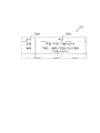
- FIG. 2 is a diagram illustrating a data structure of the learning data 210.
- the learning data 210 has a component storage area 2101 and a sample data storage area 2102.
- the component storage area 2101 and the sample data storage area 2102 are associated with each other.
- the parts storage area 2101 stores the names of parts such as piping, scaffolding, and auxiliary equipment.
- sample data storage area 2102 sample data of a part whose part name is stored in the part storage area 2101 is stored.
- the sample data is three-dimensional point group data.
- FIG. 2 a diagram is shown as sample data, but this is for explanation, and is actually point cloud data capable of recognizing a three-dimensional shape.
- the shape fitting DB 22 stores fitting information 220, which is information necessary for fitting, for parts whose learning data is stored in the member identification model DB 21.
- FIG. 3 is a diagram showing a data structure of the fitting information 220.
- the fitting information 220 includes a component storage area 2201 and a fitting data storage area 2202.
- the component storage area 2201 and the fitting data storage area 2202 are associated with each other.
- the parts storage area 2201 stores the names of parts such as piping, scaffolding, and auxiliary equipment.
- the fitting data storage area 2202 stores information necessary for fitting the parts stored in the parts storage area 2101, that is, information indicating what kind of fitting should be performed (hereinafter referred to as fitting data).
- the fitting data will be described by taking a case where the part is a scaffold as an example.
- the scaffolding is composed of a circular pipe such as an iron pipe and a plate material attached to the circular pipe. Therefore, when “scaffold” is stored in the component storage area 2101, the fitting data storage area 2202 is fitted with the information “a combination of a plane and a circular tube”, that is, fitting point cloud data with a plane and a circular pipe surface. Fitting data indicating that it should be done is stored.
- the display device 25 includes a display device such as a CRT monitor or a liquid crystal monitor.
- the control unit 11 mainly includes a segment calculation unit 111, a graph network calculation unit 112, a graph matching unit 113, a point cloud feature amount calculation unit 114, a part identification unit 115, and a shape fitting. Part 116 and a CAD fitting part 117.
- the segment calculation unit 111 divides each of the measurement data 23 and the three-dimensional CAD data 24 into a plurality of segments such as a plane segment and a curved segment. Data obtained by the segment calculation unit 111 is output to the graph network calculation unit 112. Since the specific process in which the segment calculation unit 111 divides into segments is already known, a description thereof will be omitted.
- the graph network calculation unit 112 for each of the segment of the measurement data 23 and the segment of the three-dimensional CAD data 24 divided by the segment calculation unit 111, specifically, which segment is connected to which segment, Where is the connection position, how many times the connection angle is, etc. are calculated.
- the graph network calculation unit 112 outputs the calculated connection of segments (hereinafter referred to as a graph network) to the graph matching unit 113 as structure information.
- the specific processing performed by the graph network calculation unit 112 is already known, and thus detailed description thereof is omitted.
- the graph matching unit 113 matches the graph network of the measurement data 23 generated by the graph network calculation unit 112 and the graph network of the three-dimensional CAD data 24. Specifically, the graph matching unit 113 compares the graph network of the measurement data 23 and the graph network of the three-dimensional CAD data 24 to obtain the closeness as the network structure. In addition, based on the matching result, the graph matching unit 113 determines whether the component that is the basis of the measurement data 23 is a component that has 3D design data, or the component that is the basis of the measurement data 23 is a component that does not have 3D design data. Classify. The processing performed by the graph matching unit 113 will be described in detail later.
- the point cloud feature quantity calculation unit 114 calculates a feature quantity from the measurement data 23 when the graph matching unit 113 classifies the part that is the basis of the measurement data 23 as a part that does not have 3D design data. For example, the point group feature amount calculation unit 114 calculates the features of the point group such as the variance, size, and centroid distance of a portion of the measurement data 23 in the x direction, y direction, and z direction as the feature amount. Further, the point cloud feature value calculation unit 114 calculates a feature value for the sample data stored in the member identification model DB 21. The feature amount calculated for the sample data is used when creating a learning model. In addition, since the specific process which the point cloud feature-value calculation part 114 performs is already well-known, detailed description is abbreviate
- the component identification unit 115 identifies a component based on the feature amount calculated by the point cloud feature amount calculation unit 114 using a known method such as a support vector machine.
- the component identification unit 115 compares the feature amount of the measurement data 23 calculated by the point cloud feature amount calculation unit 114 with the feature amount of the sample data stored in the member identification model DB 21, and serves as a basis of the measurement data 23. Identifies which part of the parts the sample data is stored in the member identification model DB 21 corresponds to.
- the method used by the component identification unit 115 is not limited to the support vector machine, and any method may be used as long as the identification method performs identification based on the identification rule. Further, since a known method is used for the processing performed by the component identification unit 115, detailed description thereof is omitted.
- the shape fitting unit 116 fits the measurement data 23 based on the identification result of the component identification unit 115.
- the processing of the shape fitting unit 116 will be described in detail later.
- the CAD fitting unit 117 uses the 3D CAD data 24 to fit the measurement data 23. The processing of the CAD fitting unit 117 will be described in detail later.
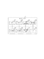
- FIG. 4 is a block diagram illustrating an example of a schematic configuration of the three-dimensional model generation apparatus 1.
- a three-dimensional model generation device 1 configured by a computer or the like includes a CPU (Central Processing Unit) 101 that is an arithmetic device, a RAM (Random Access Memory) that is a volatile storage device, and a nonvolatile memory device.
- CPU Central Processing Unit
- RAM Random Access Memory
- a memory 102 composed of a ROM (Read only Memory) that is a storage device, an external storage device 103, a communication device 104 that communicates with an external device, and a user interface such as a keyboard, mouse, or touch panel that accepts input from the user ,
- An output device 106 such as a display, a read / write device 107 such as a CD drive or a DVD drive, and an interface (I / F) 108 for connecting the control unit 11 to other units. That.
- Each functional unit of the control unit 11 is realized, for example, by the CPU 101 reading out a predetermined program stored in the memory 102 to the memory 32 and executing it.
- the predetermined program may be installed in the memory 102 in advance, downloaded from the network via the communication device 104, installed or updated, or installed or updated from the external storage device 103, for example. Alternatively, it may be installed or updated from a CD drive or DVD drive via the read / write device 107.
- the input unit 13 is realized by the input device 105.
- the output unit 12 and the communication unit 14 are realized by the communication device 104 and the I / F 108.
- the storage unit 15 is realized by the memory 102.
- the display device 25 is realized by the output device 106. Note that the output device 106 is not essential as a configuration of the three-dimensional model generation device 1, and may be connected via the I / F 108.
- the above-described configuration of the three-dimensional model generation device 1 is the main configuration for describing the features of the present embodiment, and is not limited to the above configuration.
- FIG. 5 is a flowchart showing the overall processing flow of the three-dimensional model generation apparatus 1 in the present embodiment.
- the control unit 11 issues an instruction to the three-dimensional measuring device 20 via the communication unit 14 and performs three-dimensional measurement of the component (step S10).
- the control unit 11 acquires measurement data 23 measured by the three-dimensional measuring device 20 via the communication unit 14 (step S12). Further, the control unit 11 acquires all the three-dimensional CAD data 24 stored in a three-dimensional CAD server (not shown) via the communication unit 14 (step S14).
- the measurement data 23 acquired in step S12 and the three-dimensional CAD data 24 acquired in step S14 are stored in the storage unit 15.
- the segment calculation unit 111 segments the measurement data 23 acquired in step S12, and divides the three-dimensional CAD data 24 acquired in step S14 into element planes (synonymous with segments), so that a plane segment, a curved segment, etc. Divide into a plurality of segments (step S16).
- the graph network calculation unit 112 creates a graph network for each of the measurement data 23 and the three-dimensional CAD data 24 divided into a plurality of segments in step S16 (step S18). Specifically, the graph network calculation unit 112 forms a graph network as information to add the segments of the measurement data 23 to nodes, arcs between connected segments, and the angles to be connected to arcs. In addition, the graph network calculation unit 112 converts the element plane of the three-dimensional CAD data 24 to a node, arcs between connected element planes, and graph network as information to add a connecting angle to the arc.
- the graph matching unit 113 performs matching between the graph network of the measurement data 23 calculated in step S18 and the graph network of the three-dimensional CAD data 24 (step S20).
- step S20 will be specifically described.
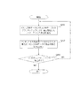
- FIG. 6 is a flowchart showing the flow of the matching process (step S20).
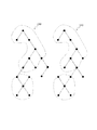
- the graph matching unit 113 compares the graph network 230 of the measurement data 23 with the graph network 240 of the three-dimensional CAD data 24, and extracts the most similar nodes and arc aggregates (step S201). As a result of comparison between the graph network 230 of the measurement data 23 and the graph network 240 of the three-dimensional CAD data 24, a plurality of regions where the graph network 230 of the measurement data 23 and the graph network 240 of the three-dimensional CAD data 24 match are extracted. Sometimes. In this case, the graph matching unit 113 extracts the largest aggregate among the plurality of regions, the region with the highest similarity, and the like.
- FIG. 7 is a diagram showing a graph network 230 of measurement data 23 and a graph network 240 of three-dimensional CAD data 24.
- nodes are segments
- arcs indicate connection of segments.
- an area surrounded by a dotted line is extracted as an aggregate in which the graph network 230 of the measurement data 23 and the graph network 240 of the three-dimensional CAD data 24 are similar.
- the graph matching unit 113 is attached to the aggregate extracted from the graph network 240 of the three-dimensional CAD data 24 in step S201 to the aggregate extracted from the graph network 230 of the measurement data 23 in step S201.
- the component names are associated (step S202). If no aggregate is extracted in step S201, the graph matching unit 113 does not associate a name in step S202 and proceeds to the next step.
- the graph matching unit 113 determines whether there is a matching node / arc aggregate (step S203).
- the graph network 230 of the measurement data 23 and the graph network 240 of the three-dimensional CAD data 24 match in a plurality of regions.
- the graph matching unit 113 performs Step S201 again.
- the graph matching unit 113 ends the matching process.
- the closeness as a structure between the graph network 230 of the measurement data 23 and the graph network 240 of the three-dimensional CAD data 24 is required.
- the closeness as a structure can also be calculated by the number of partially matching regions, the area ratio of the regions, and the like.
- the graph matching unit 113 determines whether the component that is the basis of the measurement data 23 is a component that has 3D design data, or the component that is the basis of the measurement data 23 is a component that does not have 3D design data. It is determined whether or not the component that is the basis of the measurement data 23 is a component having three-dimensional design data (step S22). Hereinafter, step S22 will be specifically described.
- the graph matching unit 113 stores the three-dimensional CAD data 24 of the part that is the basis of the point cloud data. Judge that it was input. Then, the graph matching unit 113 classifies the component that is the basis of the measurement data 23 into a component having 3D design data.
- the graph matching unit 113 may be used when there are a plurality of matching areas in the graph network 230 of the measurement data 23 and the graph network 240 of the three-dimensional CAD data 24 or when the graph network 230 of the measurement data 23 and the three-dimensional CAD data 24
- a predetermined threshold for example, 70%
- the graph matching unit 113 performs the three-dimensional CAD data 24 of the component that is the basis of the point cloud data. It is determined that is not entered. Then, the graph matching unit 113 classifies the component that is the basis of the measurement data 23 into a component that does not have 3D design data.
- step S24 When the component that is the basis of the measurement data 23 is classified as a component that does not have the 3D design data (NO in step S22), the control unit 11 determines that the component that is the basis of the measurement data 23 is a 3D model. It is determined whether or not it is a target (step S24). Hereinafter, step S24 will be specifically described.
- the point cloud feature amount calculation unit 114 calculates the feature amount of the sample data stored in the measurement data 23 and the member identification model DB 21.
- the component identification unit 115 compares the feature amount of the measurement data 23 calculated by the point cloud feature amount calculation unit 114 with the feature amount of the sample data stored in the member identification model DB 21, and serves as a basis of the measurement data 23. Identifies which part of the parts the sample data is stored in the member identification model DB 21 corresponds to.
- step S24 NO, the shape fitting unit 116 deletes the measurement data 23 from the storage unit 15 (step S26).
- step S24 YES
- the shape fitting unit 116 performs fitting based on the component identification result to generate a three-dimensional model (step S28).
- step S28 will be specifically described.
- FIG. 8 is a flowchart showing a flow of processing for generating a three-dimensional model by performing fitting based on the component identification result.
- the shape fitting unit 116 acquires, from the shape fitting DB 22, the characteristics of the part that is identified in step S24 and serves as the basis of the measurement data 23. For example, when the component that is the basis of the measurement data 23 is identified as a scaffold in step S 24, the shape fitting unit 116 acquires information “a combination of a plane and a circular tube” from the fitting data storage area 2202. (Step S280).
- the shape fitting unit 116 fits the measurement data 23 based on the information acquired in step S280 (steps S282 to S288).
- the component that is the basis of the three-dimensional model is not limited to a scaffold, and can be formed by joining a plane and a circular tube. Therefore, the shape fitting unit 116 fits a plane and a cylinder separately as described below.
- the shape fitting unit 116 extracts a plane component point group from the measurement data 23 (step S282).
- the shape fitting unit 116 performs plane fitting on the point group extracted in step S282 (step S284).
- the shape fitting unit 116 removes the point component of the plane component from the measurement data 23 (step S286). As a result, only the cylindrical surface component of the measurement data 23 remains, so the shape fitting unit 116 fits the cylindrical surface to the point group from which the plane component point group is removed in step S286 (step S288).
- planar fitting is simpler and more accurate. In general, there are more point groups belonging to a plane than point groups belonging to a curved surface. Therefore, it is desirable to perform curved surface fitting after fitting a plane.
- the CAD fitting unit 117 uses the three-dimensional CAD data 24 to fit the measurement data 23. (Step S30).
- step S30 The process of step S30 will be described using an example.
- the CAD fitting unit 117 performs the fitting of the measurement data 23 so that the matching result obtained by the graph matching unit 113 matches the three-dimensional CAD data 24 and has the same shape as the three-dimensional CAD data 24.
- the shape here is a line, a plane, a curved surface, a circular tube or the like.
- the CAD fitting unit 117 performs fitting on a portion that does not match the three-dimensional CAD data 24.
- the CAD fitting unit 117 uses the three-dimensional CAD data 24 to correct the fitting result generated in step S30 and generate a three-dimensional model (step S32). Specifically, the CAD fitting unit 117 corrects the fitting result using the standard information in the three-dimensional CAD data 24.
- the standard information is information related to the size of the pipe diameter, for example. Thereby, an error between the three-dimensional model based on the measurement result and the design data can be absorbed, and a highly accurate three-dimensional model can be generated.
- step S32 the fitting result is not corrected for portions not related to the standard such as positional deviation. This is because in the present embodiment, it is important to reproduce the measured result. Note that information (hereinafter referred to as difference information) such as the magnitude of positional deviation between the three-dimensional CAD data 24 and the generated three-dimensional model may be held.
- the control unit 11 stores the generated three-dimensional model and difference information in the storage unit 15.
- the output unit 12 outputs the three-dimensional CAD data 24, the three-dimensional model, and the difference information to the display device 25 as necessary.
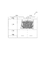
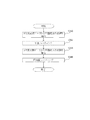
- FIG. 9 is a display example of the display device 25 when a three-dimensional model and difference information are output. As shown in FIG. 9, the display device 25 displays an image 251 displaying the 3D CAD data 24 and a generated 3D model image 252 based on the 3D CAD data 24 and the 3D model. . Thereby, design data and an actual state can be compared at a glance.
- the display device 25 displays a display area 253 for displaying parts for which the three-dimensional CAD data 24 exists, and a display area 254 for displaying parts for which the three-dimensional CAD data does not exist. Thereby, it can be easily confirmed whether or not the three-dimensional CAD data 24 exists.
- the display device 25 displays, based on the difference information, a display area 255 for displaying that the position of the part in which the three-dimensional CAD data 24 exists is different from the three-dimensional CAD data 24, and the shape of the three-dimensional CAD data 24 and the shape.
- a display area 256 is displayed to indicate that they are different.
- the generated three-dimensional model image 252 may be displayed so that the difference can be recognized.
- portions of the three-dimensional model that are not in the three-dimensional CAD data 24 are displayed in black.
- portions that are different in position and shape from the three-dimensional CAD data 24 are shaded.
- FIG. 9 is an example of display on the display device 25 when the three-dimensional model and the difference information are output, and the display form is not limited to this.
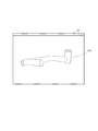
- FIG. 10 is a display example of the display device 25 when a three-dimensional model is output. As shown in FIG. 10, the generated three-dimensional model image 252 is displayed on the display device 25. Thereby, a three-dimensional model can be confirmed.
- a three-dimensional model can be automatically generated from the measurement result.
- the 3D model is generated with reference to the 3D CAD data, so that the 3D model can be generated quickly and with high accuracy.
- a highly accurate three-dimensional model can be generated by correcting a three-dimensional model generated based on three-dimensional CAD data.
- a part is identified with reference to sample data, and a 3D model is generated based on the feature of the part, thereby achieving high accuracy 3 A dimensional model can be generated.
- the measurement data when the three-dimensional model is not generated, the measurement data can be deleted to eliminate noise and increase the processing speed and accuracy.
- this invention is not limited to the above-mentioned Example, Various modifications are included.
- the above-described embodiments have been described in detail for easy understanding of the present invention, and are not necessarily limited to those having all the configurations described. It is also possible to add the configuration of another embodiment to the configuration of one embodiment. Further, it is possible to add, delete, and replace other configurations for a part of the configuration of each embodiment.
- each of the above-described configurations, functions, processing units, processing means, and the like may be realized by hardware by designing a part or all of them with, for example, a modification opportunity.
- Each of the above-described configurations, functions, and the like may be realized by software by interpreting and executing a program that realizes each function by the processor.
- Information such as programs, tables, and files for realizing each function can be stored in a memory, a hard disk, a recording device such as an SSD (Solid State Drive), or a recording medium such as an IC card, an SD card, or a DVD.
- control lines and information lines indicate what is considered necessary for explanation, and not all control lines and information warfare on the product are necessarily shown. In practice, it may be considered that almost all the components are connected to each other.
- 1 three-dimensional model generation apparatus, 11: control unit, 12: output unit, 13: input unit, 14: communication unit, 15: storage unit, 20: three-dimensional measuring instrument, 21: member identification model DB, 22: shape Fitting DB, 23: measurement data, 24: three-dimensional CAD data, 25: display device, 111: segment calculation unit, 112: graph network calculation unit, 113: graph matching unit, 114: point cloud feature value calculation unit, 115: Component identification unit, 116: shape fitting unit, 117: CAD fitting unit, 210: learning data, 220: fitting information
Landscapes
- Engineering & Computer Science (AREA)
- Theoretical Computer Science (AREA)
- Physics & Mathematics (AREA)
- General Physics & Mathematics (AREA)
- Multimedia (AREA)
- Computer Vision & Pattern Recognition (AREA)
- Software Systems (AREA)
- Computer Hardware Design (AREA)
- Evolutionary Computation (AREA)
- Geometry (AREA)
- General Engineering & Computer Science (AREA)
- Processing Or Creating Images (AREA)
- Image Generation (AREA)
Applications Claiming Priority (2)
| Application Number | Priority Date | Filing Date | Title |
|---|---|---|---|
| JP2012-270817 | 2012-12-11 | ||
| JP2012270817A JP5830004B2 (ja) | 2012-12-11 | 2012-12-11 | 3次元モデル生成装置、3次元モデル生成方法及び3次元モデル生成プログラム |
Publications (1)
| Publication Number | Publication Date |
|---|---|
| WO2014091837A1 true WO2014091837A1 (ja) | 2014-06-19 |
Family
ID=50934135
Family Applications (1)
| Application Number | Title | Priority Date | Filing Date |
|---|---|---|---|
| PCT/JP2013/079846 Ceased WO2014091837A1 (ja) | 2012-12-11 | 2013-11-05 | 3次元モデル生成装置、3次元モデル生成方法及び3次元モデル生成プログラム |
Country Status (2)
| Country | Link |
|---|---|
| JP (1) | JP5830004B2 (enExample) |
| WO (1) | WO2014091837A1 (enExample) |
Cited By (3)
| Publication number | Priority date | Publication date | Assignee | Title |
|---|---|---|---|---|
| JP2020204806A (ja) * | 2019-06-14 | 2020-12-24 | 日立Geニュークリア・エナジー株式会社 | 計測支援装置および計測支援方法 |
| JP2021108158A (ja) * | 2016-06-30 | 2021-07-29 | キヤノンマーケティングジャパン株式会社 | 仮想空間制御装置、その制御方法、及びプログラム |
| EP3879260A1 (en) | 2020-03-10 | 2021-09-15 | NEC Corporation | Abnormal part display apparatus, abnormal part display system, abnormal part display method, and abnormal part display program |
Families Citing this family (11)
| Publication number | Priority date | Publication date | Assignee | Title |
|---|---|---|---|---|
| US9916398B2 (en) * | 2013-12-10 | 2018-03-13 | Dassault Systemes | Laser scan re-engineering of 3D CAD models |
| CN104899378A (zh) * | 2015-06-10 | 2015-09-09 | 上海大学 | 基于bim和三维测量的高层钢结构数字化安装方法 |
| JP6526488B2 (ja) * | 2015-06-16 | 2019-06-05 | 株式会社日立製作所 | 3次元モデル生成装置、構成部材判定方法、およびプログラム |
| JP2020052032A (ja) * | 2018-09-21 | 2020-04-02 | ファナック株式会社 | 撮像装置及び撮像システム |
| JP7237541B2 (ja) * | 2018-11-21 | 2023-03-13 | 日立Geニュークリア・エナジー株式会社 | マップ生成装置、および、マップ生成方法 |
| EP3675061A1 (en) | 2018-12-29 | 2020-07-01 | Dassault Systèmes | Forming a dataset for inference of editable feature trees |
| JP2020204805A (ja) * | 2019-06-14 | 2020-12-24 | パナソニックIpマネジメント株式会社 | 表示方法、画像生成装置、及び、プログラム |
| WO2021176877A1 (ja) * | 2020-03-02 | 2021-09-10 | 富士フイルム株式会社 | 画像処理装置、画像処理方法、及び画像処理プログラム |
| JP7549987B2 (ja) * | 2020-07-17 | 2024-09-12 | 日立Geニュークリア・エナジー株式会社 | アズビルト化支援装置およびアズビルト化支援方法 |
| CN116432373A (zh) | 2022-01-13 | 2023-07-14 | 株式会社理光 | 三维形状创建装置、系统、方法以及存储介质和计算机装置 |
| CN114792372B (zh) * | 2022-06-22 | 2022-11-04 | 广东工业大学 | 一种基于多头两级注意力的三维点云语义分割方法及系统 |
Citations (4)
| Publication number | Priority date | Publication date | Assignee | Title |
|---|---|---|---|---|
| JP2003242186A (ja) * | 2002-02-20 | 2003-08-29 | Toyota Motor Corp | Cadデータ処理装置 |
| JP2006195850A (ja) * | 2005-01-17 | 2006-07-27 | Mitsubishi Electric Corp | 設備更新情報抽出装置及び方法 |
| JP2010061259A (ja) * | 2008-09-02 | 2010-03-18 | Hitachi Ltd | 3次元立体形状データ変換装置および変換方法 |
| JP2010211434A (ja) * | 2009-03-10 | 2010-09-24 | Hitachi Ltd | 設計支援装置 |
-
2012
- 2012-12-11 JP JP2012270817A patent/JP5830004B2/ja not_active Expired - Fee Related
-
2013
- 2013-11-05 WO PCT/JP2013/079846 patent/WO2014091837A1/ja not_active Ceased
Patent Citations (4)
| Publication number | Priority date | Publication date | Assignee | Title |
|---|---|---|---|---|
| JP2003242186A (ja) * | 2002-02-20 | 2003-08-29 | Toyota Motor Corp | Cadデータ処理装置 |
| JP2006195850A (ja) * | 2005-01-17 | 2006-07-27 | Mitsubishi Electric Corp | 設備更新情報抽出装置及び方法 |
| JP2010061259A (ja) * | 2008-09-02 | 2010-03-18 | Hitachi Ltd | 3次元立体形状データ変換装置および変換方法 |
| JP2010211434A (ja) * | 2009-03-10 | 2010-09-24 | Hitachi Ltd | 設計支援装置 |
Cited By (6)
| Publication number | Priority date | Publication date | Assignee | Title |
|---|---|---|---|---|
| JP2021108158A (ja) * | 2016-06-30 | 2021-07-29 | キヤノンマーケティングジャパン株式会社 | 仮想空間制御装置、その制御方法、及びプログラム |
| JP7208549B2 (ja) | 2016-06-30 | 2023-01-19 | キヤノンマーケティングジャパン株式会社 | 仮想空間制御装置、その制御方法、及びプログラム |
| JP2020204806A (ja) * | 2019-06-14 | 2020-12-24 | 日立Geニュークリア・エナジー株式会社 | 計測支援装置および計測支援方法 |
| JP7233313B2 (ja) | 2019-06-14 | 2023-03-06 | 日立Geニュークリア・エナジー株式会社 | 計測支援装置および計測支援方法 |
| EP3879260A1 (en) | 2020-03-10 | 2021-09-15 | NEC Corporation | Abnormal part display apparatus, abnormal part display system, abnormal part display method, and abnormal part display program |
| US11869179B2 (en) | 2020-03-10 | 2024-01-09 | Nec Corporation | Abnormal part display apparatus, abnormal part display system, abnormal part display method, and abnormal part display program |
Also Published As
| Publication number | Publication date |
|---|---|
| JP2014115915A (ja) | 2014-06-26 |
| JP5830004B2 (ja) | 2015-12-09 |
Similar Documents
| Publication | Publication Date | Title |
|---|---|---|
| JP5830004B2 (ja) | 3次元モデル生成装置、3次元モデル生成方法及び3次元モデル生成プログラム | |
| CN107810522B (zh) | 实时、基于模型的对象检测及姿态估计 | |
| JP4785598B2 (ja) | 類似形状検索装置 | |
| JP2009128075A (ja) | 物体認識方法 | |
| JP2009129189A (ja) | 物体認識方法 | |
| JP2023525535A (ja) | 3次元画像内の表面特徴を識別する方法及び装置 | |
| KR102182654B1 (ko) | 증강현실을 활용한 수치지형도 검수 방법 | |
| Ahmadabadian et al. | Stereo‐imaging network design for precise and dense 3D reconstruction | |
| Jeon et al. | A touch-probe path generation method through similarity analysis between the feature vectors in new and old models | |
| Al Nasr et al. | Intensity-based skeletonization of CryoEM gray-scale images using a true segmentation-free algorithm | |
| JP6280425B2 (ja) | 画像処理装置、画像処理システム、3次元計測器、画像処理方法及び画像処理プログラム | |
| JP5949002B2 (ja) | 画像マッチング方法、およびこの方法を用いた画像マッチング装置およびプログラム | |
| CN110717291B (zh) | 一种焊接结构件变形仿真方法、装置、设备及存储介质 | |
| Skorkovská et al. | A Simple and Robust Approach to Computation of Meshes Intersection. | |
| JP6216211B2 (ja) | 3次元モデル生成装置、3次元モデル生成方法及びプログラム | |
| JP7237541B2 (ja) | マップ生成装置、および、マップ生成方法 | |
| JP7265143B2 (ja) | 表示制御方法、表示制御プログラムおよび情報処理装置 | |
| Munkelt et al. | Automatic complete high-precision optical 3D measurement of air cooling-holes of gas turbine vanes for repair | |
| CN102831264A (zh) | 基于cad的地图信息转换方法 | |
| JP6237002B2 (ja) | モデル計測装置、モデル計測方法、及びプログラム | |
| JP4912756B2 (ja) | ポリゴンデータ分割方法およびポリゴンデータ分割装置 | |
| Do et al. | Error assessment of point cloud and BIM models to actual works | |
| Avagyan et al. | Scanned three-dimensional model matching and comparison algorithms for manufacturing applications | |
| JP2662856B2 (ja) | 形状特徴計測装置および方法 | |
| Yu et al. | Point cloud registration algorithm based on neighborhood feature similarity for contour fitting |
Legal Events
| Date | Code | Title | Description |
|---|---|---|---|
| 121 | Ep: the epo has been informed by wipo that ep was designated in this application |
Ref document number: 13861959 Country of ref document: EP Kind code of ref document: A1 |
|
| NENP | Non-entry into the national phase |
Ref country code: DE |
|
| 122 | Ep: pct application non-entry in european phase |
Ref document number: 13861959 Country of ref document: EP Kind code of ref document: A1 |