WO2014091827A1 - 石炭不活性化処理装置およびこれを利用する改質石炭製造設備 - Google Patents
石炭不活性化処理装置およびこれを利用する改質石炭製造設備 Download PDFInfo
- Publication number
- WO2014091827A1 WO2014091827A1 PCT/JP2013/078905 JP2013078905W WO2014091827A1 WO 2014091827 A1 WO2014091827 A1 WO 2014091827A1 JP 2013078905 W JP2013078905 W JP 2013078905W WO 2014091827 A1 WO2014091827 A1 WO 2014091827A1
- Authority
- WO
- WIPO (PCT)
- Prior art keywords
- coal
- processing gas
- gas
- carbon monoxide
- processing
- Prior art date
- Legal status (The legal status is an assumption and is not a legal conclusion. Google has not performed a legal analysis and makes no representation as to the accuracy of the status listed.)
- Ceased
Links
Images


Classifications
-
- C—CHEMISTRY; METALLURGY
- C10—PETROLEUM, GAS OR COKE INDUSTRIES; TECHNICAL GASES CONTAINING CARBON MONOXIDE; FUELS; LUBRICANTS; PEAT
- C10L—FUELS NOT OTHERWISE PROVIDED FOR; NATURAL GAS; SYNTHETIC NATURAL GAS OBTAINED BY PROCESSES NOT COVERED BY SUBCLASSES C10G OR C10K; LIQUIFIED PETROLEUM GAS; USE OF ADDITIVES TO FUELS OR FIRES; FIRE-LIGHTERS
- C10L9/00—Treating solid fuels to improve their combustion
- C10L9/02—Treating solid fuels to improve their combustion by chemical means
- C10L9/06—Treating solid fuels to improve their combustion by chemical means by oxidation
-
- C—CHEMISTRY; METALLURGY
- C10—PETROLEUM, GAS OR COKE INDUSTRIES; TECHNICAL GASES CONTAINING CARBON MONOXIDE; FUELS; LUBRICANTS; PEAT
- C10L—FUELS NOT OTHERWISE PROVIDED FOR; NATURAL GAS; SYNTHETIC NATURAL GAS OBTAINED BY PROCESSES NOT COVERED BY SUBCLASSES C10G OR C10K; LIQUIFIED PETROLEUM GAS; USE OF ADDITIVES TO FUELS OR FIRES; FIRE-LIGHTERS
- C10L5/00—Solid fuels
- C10L5/02—Solid fuels such as briquettes consisting mainly of carbonaceous materials of mineral or non-mineral origin
- C10L5/04—Raw material of mineral origin to be used; Pretreatment thereof
-
- C—CHEMISTRY; METALLURGY
- C10—PETROLEUM, GAS OR COKE INDUSTRIES; TECHNICAL GASES CONTAINING CARBON MONOXIDE; FUELS; LUBRICANTS; PEAT
- C10L—FUELS NOT OTHERWISE PROVIDED FOR; NATURAL GAS; SYNTHETIC NATURAL GAS OBTAINED BY PROCESSES NOT COVERED BY SUBCLASSES C10G OR C10K; LIQUIFIED PETROLEUM GAS; USE OF ADDITIVES TO FUELS OR FIRES; FIRE-LIGHTERS
- C10L9/00—Treating solid fuels to improve their combustion
- C10L9/08—Treating solid fuels to improve their combustion by heat treatments, e.g. calcining
-
- C—CHEMISTRY; METALLURGY
- C10—PETROLEUM, GAS OR COKE INDUSTRIES; TECHNICAL GASES CONTAINING CARBON MONOXIDE; FUELS; LUBRICANTS; PEAT
- C10L—FUELS NOT OTHERWISE PROVIDED FOR; NATURAL GAS; SYNTHETIC NATURAL GAS OBTAINED BY PROCESSES NOT COVERED BY SUBCLASSES C10G OR C10K; LIQUIFIED PETROLEUM GAS; USE OF ADDITIVES TO FUELS OR FIRES; FIRE-LIGHTERS
- C10L2290/00—Fuel preparation or upgrading, processes or apparatus therefore, comprising specific process steps or apparatus units
- C10L2290/02—Combustion or pyrolysis
-
- C—CHEMISTRY; METALLURGY
- C10—PETROLEUM, GAS OR COKE INDUSTRIES; TECHNICAL GASES CONTAINING CARBON MONOXIDE; FUELS; LUBRICANTS; PEAT
- C10L—FUELS NOT OTHERWISE PROVIDED FOR; NATURAL GAS; SYNTHETIC NATURAL GAS OBTAINED BY PROCESSES NOT COVERED BY SUBCLASSES C10G OR C10K; LIQUIFIED PETROLEUM GAS; USE OF ADDITIVES TO FUELS OR FIRES; FIRE-LIGHTERS
- C10L2290/00—Fuel preparation or upgrading, processes or apparatus therefore, comprising specific process steps or apparatus units
- C10L2290/08—Drying or removing water
-
- C—CHEMISTRY; METALLURGY
- C10—PETROLEUM, GAS OR COKE INDUSTRIES; TECHNICAL GASES CONTAINING CARBON MONOXIDE; FUELS; LUBRICANTS; PEAT
- C10L—FUELS NOT OTHERWISE PROVIDED FOR; NATURAL GAS; SYNTHETIC NATURAL GAS OBTAINED BY PROCESSES NOT COVERED BY SUBCLASSES C10G OR C10K; LIQUIFIED PETROLEUM GAS; USE OF ADDITIVES TO FUELS OR FIRES; FIRE-LIGHTERS
- C10L2290/00—Fuel preparation or upgrading, processes or apparatus therefore, comprising specific process steps or apparatus units
- C10L2290/58—Control or regulation of the fuel preparation of upgrading process
Definitions
- the present invention relates to a coal inactivation treatment apparatus and a modified coal production facility using the same.
- Low-grade coal with high water content such as lignite and sub-bituminous coal has a low calorific value per unit weight, so it is dried and dry-distilled by heating, and in a low-oxygen atmosphere.
- the modified coal has an increased calorific value per unit weight while preventing spontaneous ignition.
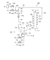
- the apparatus 500 includes a processing tower 501 that circulates the coal 521 that is the carbonized carbon from one upper side to the other lower side.
- a front end side of an introduction pipe 511 for introducing a processing gas 533 containing oxygen at a low concentration into the processing tower 501 and a processing gas 534 circulated through the processing tower 501 to the outside.
- a plurality of discharge pipes 512 to be discharged are connected to the base end side along the vertical direction.
- the proximal end side of the introduction pipe 511 is connected to the distal end side of the supply pipe 513 that supplies the processing gas 533.
- the distal end side of the air supply pipe 514 that supplies the air 531 and the distal end side of the nitrogen supply pipe 515 that supplies the nitrogen gas 532 are connected to the proximal end side of the feed pipe 513.
- the base end side of the nitrogen supply pipe 515 is connected to a nitrogen supply source 516 such as a nitrogen gas tank.
- the base end side of the air supply pipe 514 is open to the atmosphere.
- flow rate adjusting valves 514a and 515a are provided, respectively.
- a blower 513a is provided in the middle of the feed pipe 513.
- a humidity adjustment device 513b for adjusting the temperature and humidity of the processing gas 533 is provided.
- a proximal end side of a branch pipe 518 that discharges the processing gas 533 out of the system is connected between the blower 513a of the supply pipe 513 and the humidity adjusting device 513b.
- the proximal end side of the circulation pipe 517 is connected to the distal end side of the discharge pipe 512.
- the distal end side of the circulation pipe 517 is connected to the proximal end side of the feed pipe 513.
- the carbonized coal 521 is supplied into the treatment tower 501 from above, and the air flow is controlled by controlling the opening of the flow rate adjusting valves 514a and 515a and the operation of the blower 513a.
- 531 and the nitrogen gas 532 are fed from the supply pipes 514 and 515 to the feed pipe 513 to be mixed into the processing gas 533 and the operation of the humidity adjusting device 513b is controlled to control the processing gas.
- Adjust the temperature and humidity of 533 The processing gas 533 whose temperature and humidity are adjusted in this way is introduced into the processing tower 501 through the introduction pipe 511, and the surface of the coal 521 inside the processing tower 501 is inactivated.
- the exhaust pipe 512 is exhausted to the circulation pipe 517 as used processing gas 534.
- the used processing gas 534 discharged to the circulation pipe 517 is returned to the feeding pipe 513 and mixed together with new air 531 and nitrogen gas 532 from the supply pipes 514 and 515 to form a new processing gas. It is used again as 533.
- the processing gas 533 having the same amount as the air 531 and the nitrogen gas 532 supplied from the supply pipes 514 and 515 is discharged from the branch pipe 518 to the outside of the system.
- the coal 521 reacts with oxygen in the treatment gas 533 to generate a very small amount of carbon monoxide and carbon dioxide. Since the used processing gas 534 used for the inactivation processing of the coal 521 inside the processing tower 501 is sent to the feeding pipe 513 through the discharge pipe 512 and the circulation pipe 517, The carbon monoxide concentration in the processing gas 533 increases in proportion to the operation time as the operation time elapses.
- An object of the present invention is to provide a coal inactivation treatment apparatus capable of suppressing an increase in carbon concentration and a modified coal production facility using the same.
- the coal inactivation processing apparatus for solving the above-described problems is a coal inactivation processing apparatus that inactivates coal with a processing gas containing oxygen.
- the coal inactivation processing apparatus for solving the above-described problem is the coal inactivation processing apparatus according to the first invention described above, wherein the carbon monoxide treatment means supplies the processing gas. Extracting process gas extracting means; oxidizing means for adjusting carbon monoxide concentration in the processing gas by oxidizing carbon monoxide in the processing gas extracted by the processing gas extracting means; And a carbon monoxide-adjusted process gas supply means for supplying the process gas having the adjusted carbon concentration to the process gas supply means or the process gas circulation means.
- a coal inactivation processing apparatus for solving the above-described problem is the coal inactivation processing apparatus according to the second invention described above, wherein the oxidation means is monooxidized in the processing gas. It is an oxidation catalyst that oxidizes carbon, a combustion furnace that burns the processing gas together with the supplied fuel, or a regenerative combustion exhaust gas treatment device that burns the processing gas together with the supplied fuel.
- a coal inactivation processing apparatus for solving the above-described problems is the coal inactivation processing apparatus according to the second invention described above, wherein the processing gas is extracted by the processing gas extraction means.
- Extraction amount adjusting means for adjusting an extraction amount
- processing gas state detecting means for detecting a concentration of carbon monoxide in the processing gas flowing through the processing gas supply means or the processing gas circulation means
- the processing gas state detection means And a control means for controlling the extraction amount adjusting means based on the carbon monoxide concentration of the processing gas detected in (1).
- a coal inactivation processing apparatus for solving the above-described problem is the coal inactivation processing apparatus according to the fourth invention described above, wherein the control means is the processing gas state detection means.
- the extraction amount adjusting means is controlled to extract the processing gas by the extraction means, and is detected by the processing gas state detection means.
- the extraction amount adjusting means is controlled so that the extraction means does not extract the processing gas when the carbon monoxide concentration of the processing gas is equal to or lower than a lower limit value smaller than the upper limit value.
- the reformed coal production facility for solving the above-mentioned problems includes a coal drying means for drying coal, a coal dry distillation means for dry distillation of the dry coal dried by the coal drying means, and the coal dry distillation means. And a coal deactivation treatment apparatus according to the first aspect of the invention for deactivating the dry distillation coal cooled by the coal cooling means. And
- the reformed coal production facility for solving the above-described problems includes a coal drying means for drying coal, a coal dry distillation means for carbonizing dry coal dried by the coal drying means, and the coal dry distillation means.
- Coal dry distillation means is provided so as to cover the inner cylinder to which the coal is supplied, an outer cylinder in which heated gas is supplied to indirectly heat the inner cylinder, and the inner cylinder in the inner cylinder
- a carbon dioxide exhausting means for exhausting carbonized gas generated by heating coal, and supplying the fuel fed to the combustion furnace or the regenerative combustion exhaust gas treatment device by the carbonized gas exhausted by the carbonized gas exhausting means Further comprising a feeding means
- the carbon monoxide concentration in the processing gas is adjusted so as to reduce the carbon monoxide concentration in the processing gas.
- the carbon oxide processing means even if the processing gas used in the apparatus main body is returned to the processing gas supply means by the processing gas circulation means, it is sent into the processing apparatus main body by the processing gas supply means. An increase in the concentration of carbon monoxide in the process gas to be supplied can be suppressed.
- the coal deactivation treatment apparatus is installed in a building that is a closed space, an increase in carbon monoxide concentration in the building can be suppressed. Can be held.
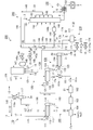
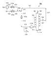
- a coal drying apparatus 110 that is a coal drying means for drying low-grade coal (low-quality coal) 1 that is coal having a high water content such as lignite and sub-bituminous coal is the low-grade coal 1.
- a hopper 111 for receiving the inside, an inner cylinder (main body barrel) 112 that is rotatably supported and supplies the low-grade coal 1 in the hopper 111 from one end side (base end side) to the inside, and the inner cylinder 112
- An outer cylinder (jacket) 113 that is fixedly supported so as to cover the outer peripheral surface of the inner cylinder 112 while being able to rotate and is supplied with steam 11 as a heating medium inside (between the inner cylinder 112),
- the dried charcoal 2 connected to the other end side (tip side) of the inner cylinder 112 and dried so as to allow the inner cylinder 112 to rotate is dropped downward from the other end side (tip side) of the inner cylinder 112.
- a shooter 114 for delivery.
- a distal end side of an inert gas supply line 115 that supplies an inert gas 12 such as nitrogen gas is connected to one end side (base end side) of the inner cylinder 112 of the coal drying apparatus 110.
- An upper end of the shooter 114 is connected to one end side of an exhaust line 116 that discharges the inert gas 12 containing carbon monoxide or water vapor.
- the other end of the exhaust line 116 is connected to a cyclone separator 117 that separates and collects the pulverized coal 2a generated by drying the low-grade coal 1 from the inert gas 12.
- a circulation line 118 Connected to the cyclone separator 117 is one end side (base end side) of a circulation line 118 having a condenser 118a for condensing and removing water vapor in the inert gas 12 from which the pulverized coal 2a has been separated into water 13. is doing.
- the other end side (front end side) of the circulation line 118 is connected to the middle of the inert gas supply line 115.
- the lower part of the shooter 114 of the coal drying apparatus 110 communicates with the upstream side in the transport direction of a dry coal transport line 119 such as a belt conveyor that transports the dry coal 2 sent from the shooter 114.
- the downstream side of the dry coal conveyance line 119 in the conveyance direction communicates with a coal carbonization device 120 that carbonizes the dry coal 2.
- One end side (base end side) of an exhaust line 126 for discharging a dry distillation gas (pyrolysis gas) 14 such as carbon monoxide, water vapor or tar is connected to the upper part of the shooter 124 of the coal carbonization apparatus 120.
- the other end side (front end side) of the exhaust line 126 is connected to a combustion furnace 127 to which air 15 and the auxiliary combustion agent 16 are supplied.
- a part of the inert gas 12 from which the water 13 has been removed in the circulation line 118 of the coal drying apparatus 110 is extracted from the circulation line 118 and supplied into the combustion furnace 127. 128 are connected.
- One end side (base end side) of a heating gas supply line 125 for supplying the heating gas 17 generated in the combustion furnace 127 is connected to the combustion furnace 127.
- the other end side (tip end side) of the heated gas supply line 125 communicates with the inner side of the outer cylinder 123.
- the outer cylinder (jacket) 133 and the inner cylinder 132 are connected to the other end side (front end side) of the inner cylinder 132 and cooled so that the carbonized carbon 3 is cooled. And a shooter 134 that drops and sends downward from the other end side (front end side).
- the lower side of the shooter 134 of the cooling device 130 communicates with the upstream side in the conveying direction of the dry distillation coal transfer line 139 such as a belt conveyor for transferring the dry distillation coal 3 sent from the shooter 134.
- the downstream side of the dry distillation coal transfer line 139 in the transfer direction communicates with the upper portion of the apparatus main body (processing tower) 141 of the coal inactivation processing apparatus 140 which is an inactivation processing means for inactivating the dry distillation coal 3. ing.
- An air supply pipe 145 supplies air 15 into the tube 144, and a nitrogen supply pipe 146 for supplying nitrogen gas 27 is connected to the proximal end side of the delivery line 144 to the feed pipe 144.
- the leading end side of the introduction pipe 142 and the proximal end side of the discharge pipe 143 are connected together in the vertical direction.
- a part of the processing gas 31 is extracted from the supply pipe 144 between the blower 144a of the supply pipe 144 and the humidity adjusting apparatus 144b and is supplied to the apparatus main body 171 of the carbon monoxide treatment apparatus 170.
- One end side (base end side) of the extraction pipe 172 to be fed is connected.
- the carbon monoxide treatment apparatus 170 includes an apparatus main body 171 connected to the other end side (front end side) of the extraction pipe 172, and one end side (front end side) connected to the apparatus main body 171, and fuel into the apparatus main body 171. 28, a fuel supply pipe 173 for supplying air 28, an air supply pipe 174 for supplying air 15 into the apparatus main body 171 connected at one end side (distal end side) to the apparatus main body 171, and a base end side connected to the apparatus main body 171.
- the apparatus main body 171 of the carbon monoxide treatment apparatus 170 is an apparatus having a function of treating the treatment gas 31 with the fuel 28 and the air 15 to oxidize carbon monoxide in the treatment gas 31.
- a device having an oxidation function of CO such as an incinerator or a regenerative thermo oxidizer (RTO) can be used.
- the catalyst promotes an oxidation reaction of carbon monoxide in the processing gas 31 by contact with the air 15, and is, for example, a hopcalite-based CO such as CuMn 2 O 4 or CuZnO.
- Oxidation catalysts such as noble metal-easily reducing oxide-based CO catalysts such as Pt / SnO 2 and Pd / CeO 2 , for example, gold nanoparticle-based CO oxidation catalysts such as Au / TiO 2 and Au / Fe 2 O 3 It is also possible to use it.
- the lower part of the apparatus main body 141 of the coal deactivation processing apparatus 140 communicates with a kneading apparatus 151 that is a kneading means for mixing the deactivated modified coal 4 with a binder 5 such as starch and water 6. ing.
- the kneading device 151 communicates with a compression device 152 which is a compression means for compressing the reformed coal 4 kneaded with the binder 5 and the water 6 and molding the reformed coal 4 into a molded coal 7.
- One end side (base end side) of an exhaust gas line 161 having a delivery blower 161 a for discharging the exhaust gas 17 a of the heated gas 17 from the inside of the outer cylinder 123 is connected to the outer cylinder 123 of the coal carbonization device 120.
- the exhaust gas line 161 is provided with a capacitor 161b for cooling the exhaust gas 17a.
- the coal drying device 110 as coal drying means is constituted by the dry coal conveyance line 119 and the like, and the hopper 121, the inner cylinder 122, the outer cylinder 123, the shooter 124, the heated gas supply line 125, the exhaust gas
- the line 126, the combustion furnace 127, the extraction line 128 and the like constitute a coal carbonization device 120 which is a coal carbonization means, and the exhaust line 126 and the like constitute a carbonization gas discharge means, and the hopper 131, the inner cylinder 132, In the outer cylinder 133, the shooter 134, the carbonized coal transport line 139, etc.
- a cooling device 130 which is a dry distillation coal cooling means is configured, and the device main body 141, the introduction pipe 142, the discharge pipe 143, the supply pipe 144, the blower 144a, the humidity adjusting device 144b, and the air supply.
- the coal deactivation treatment device 140 is constituted by the pipe 145, the nitrogen supply tube 146, the flow rate adjusting valves 145a, 146a, the nitrogen supply source 147, the circulation tube 148, the carbon monoxide treatment device 170, etc.
- a processing gas supply means is constituted by the circulation pipe 148 and the like, and a processing gas is constituted by the discharge pipe 143 and the circulation pipe 148 and the like.
- a ring means is formed, and the kneading device 151, the compression device 152, and the like constitute a coal forming apparatus 150 that is a coal forming apparatus, and the exhaust gas line 161, the denitration device 162, the electrostatic precipitator 163, and the desulfurization device.
- the 164 or the like constitutes an exhaust gas treatment device 160 which is an exhaust gas treatment means.
- the feed pipe 176, the exhaust pipe 177, etc. constitute a carbon monoxide treatment device 170 which is a carbon monoxide treatment means
- the extraction pipe 172 etc. constitute a process gas extraction means
- the fuel supply pipe 173, the air supply pipe 174, the flow rate adjusting valves 173a, 174a, etc. constitute an oxidizing means, and the exhaust pipe 17 5.
- the feed pipe 176 and the like constitute carbon monoxide adjusted process gas feed means, the coal drying device 110, the coal carbonization device 120, the cooling device 130, the coal inactivation treatment device 140,
- the reformed coal production facility 100 is constituted by the coal molding apparatus 150, the exhaust gas treatment apparatus 160, the carbon monoxide treatment apparatus 170, and the like.
- the inert gas 12 (about 150 to 200 ° C.) fed into the inner cylinder 112 of the coal drying apparatus 110 is pulverized coal 2a (particle size: 100 ⁇ m) generated by drying the low-grade coal 1. ) And water vapor from above the shooter 114 through the exhaust line 116 to the cyclone separator 117 to separate the pulverized coal 2a, and then to the circulation line 118. After cooling and separating and removing the water 13, most (about 85%) of the water 13 is returned to the inert gas supply line 115 and sent again into the inner cylinder 112 together with new inert gas 12. While being fed and reused, a part (about 15%) is fed to the combustion furnace 127 of the coal carbonization device 120 via the extraction line 128.
- the dry coal 2 (about 150 to 200 ° C.) supplied to the hopper 121 of the coal carbonization device 120 is fed into the inner cylinder (main body trunk) 122, and with the rotation of the inner cylinder 122,
- approximately 1000 to 1100 ° C. is uniformly heated and distilled (350 to 450 ° C.) to form dry-distilled coal 3 (average particle size: about 5 mm), and is supplied into the hopper 131 of the cooling device 130 via the shooter 124.
- the dry distillation gas 14 (350 to 450 ° C.) generated by dry distillation in the inner cylinder 122 of the coal dry distillation apparatus 120 is supplied to the combustion furnace 127 from above the shooter 124 via the exhaust line 126. Then, it is burned together with the inert gas 12 (including carbon monoxide) and air 15 (the auxiliary combustor 16 if necessary), and used to generate the heated gas 17.
- the carbonized carbon 3 (350 to 450 ° C.) supplied to the hopper 131 of the cooling device 130 is fed into the inner cylinder (main body cylinder) 132 and stirred as the inner cylinder 132 rotates. However, by moving from one end side to the other end side of the inner cylinder 132, the shooter 134 is cooled evenly by the cooling water 18 showered in the inner cylinder 132 (about 50 to 60 ° C.).
- the cooling water 18 showered in the inner cylinder 132 of the cooling device 130 is vaporized as the carbonized coal 3 is cooled, and is sent out of the system as steam 20 from above the shooter 134. .
- the dry-distilled coal 3 (about 50 to 60 ° C.) supplied from the upper part of the apparatus main body 141 of the coal inactivation treatment apparatus 140 is activated carbon (radical) generated by dry-distillation, and the flow rate regulating valves 145a and 146a.
- the air 15 and the nitrogen gas 27 are fed from the supply pipes 145 and 146 to the supply pipe 144 and mixed to form the processing gas 31, and the wet temperature
- the adjusting device 144b By controlling the operation of the adjusting device 144b and reacting with oxygen in the processing gas 31 whose temperature and humidity are adjusted, it is inactivated and becomes the modified coal 4 (average particle size: around 5 mm). It is fed from the lower part of the apparatus main body 141 to the kneading apparatus 151.
- the processing gas (about 50 to 70 ° C.) 33 used for the inactivation processing of the dry distillation coal 3 inside the apparatus main body 141 of the coal inactivation processing apparatus 140 is discharged from the apparatus main body 141 to the exhaust pipe. 143, returned to the feed pipe 144 through the circulation pipe 148, mixed with new air 15 and nitrogen gas 27 from the supply pipes 145 and 146, and reused as a new process gas 31. Is done.
- the reformed coal 4 (about 30 ° C.) fed to the kneading device 151 is kneaded together with the binder 5 and the water 6, then fed to the compression device 152, and compression molded. It becomes cast charcoal 7.
- the coal deactivation processing apparatus 140 as described above includes a circulation pipe 148 that is connected to the discharge pipe 143 and connected to the supply pipe 144, so that the dry distillation is performed in the apparatus main body 141.
- the carbon monoxide gas generated when the charcoal 3 is inactivated is contained in the used processing gas 33. For this reason, conventionally, there was a possibility that the concentration of carbon monoxide in the processing gas would increase as the operating time passed.
- the modified coal production facility 100 according to the present embodiment made in view of such a problem further operates as follows in order to suppress an increase in the concentration of carbon monoxide in the processing gas.
- a part of the processing gas 31 fed to the introduction pipe 142 by controlling the operation of the blower 144 a is extracted by the extraction pipe 172, and the carbon monoxide treatment apparatus 170 is extracted via the extraction pipe 172.
- Air 15 (If necessary, the opening of the flow rate adjusting valve 173a is controlled to supply oil (for example, oil supplied to the apparatus main body 171 of the carbon monoxide treatment apparatus 170 through the fuel supply pipe 173).
- the carbon monoxide concentration-adjusted processing gas 32 is discharged from the apparatus main body 171 through the discharge pipe 175, and is supplied to the supply pipe 144 through the supply pipe 176, and if necessary.
- the gas is exhausted outside the system through the exhaust pipe 177.
- the used processing gas 33 discharged from the discharge pipe 143 of the coal deactivation processing apparatus 140 is returned to the feed pipe 144 by the circulation pipe 148, but by the blower 144 a.
- a part of the processing gas 31 fed to the introduction pipe 142 is carbon monoxide concentration adjusted by reducing the carbon monoxide concentration in the processing gas 31 by the apparatus main body 171 of the carbon monoxide processing apparatus 170. Since it becomes the processing gas 32 and a part of the processing gas 32 whose carbon monoxide concentration has been adjusted is returned to the feeding pipe 144 and fed to the introduction pipe 142, it is fed by the blower 144a and sent to the introduction pipe 142a.
- the processing gas 31 introduced into the apparatus main body 141 through the pipe 142 can suppress an increase in the carbon monoxide concentration.
- the introduction pipe 142 allows the apparatus to be used.
- An increase in the concentration of carbon monoxide in the processing gas 31 introduced into the main body 141 can be suppressed.
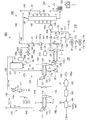
- FIG. 1 A second embodiment of the coal inactivation processing apparatus and the modified coal production facility using the same according to the present invention will be described with reference to FIG.
- This embodiment has a configuration in which the fuel supply pipe for supplying fuel to the carbon monoxide treatment apparatus included in the first embodiment shown in FIG. 1 and described above is changed.
- the other configurations are generally the same as those shown in FIG. 1 and described above, and the same devices are denoted by the same reference numerals, and redundant descriptions are omitted as appropriate.
- the coal inactivation processing apparatus 240 is connected to the apparatus main body 171 at one end side (front end side), and supplies the dry distillation gas 14 as fuel into the apparatus main body 171.
- a carbon monoxide treatment device 270 having a tube 273 is provided.
- the base end side of the fuel supply pipe 273 is located between the front end side and the base end side of the exhaust line 126 that discharges the dry distillation gas 14 discharged from the inner cylinder 122 of the dry distillation apparatus 120 to the combustion furnace 127. It is connected.
- a part of the dry distillation gas 14 discharged from the inner cylinder 122 is supplied to the fuel supply pipe 273.
- a flow rate adjusting valve 273a is provided in the middle of the fuel supply pipe 273.
- 146, the flow regulating valves 145a and 146a, the nitrogen supply source 147, the circulation pipe 148, the carbon monoxide treatment apparatus 270, and the like constitute a coal inactivation treatment apparatus 240, and the apparatus main body 171 and the extraction pipe 172
- the carbon monoxide treatment device in which the fuel supply pipe 273, the air supply pipe 174, the flow rate adjusting valves 273a and 174a, the discharge pipe 175, the supply pipe 176, the exhaust pipe 177, etc. are carbon monoxide treatment means.
- the reformed coal production facility 200 is constituted by the coal carbonization device 120, the cooling device 130, the coal inactivation treatment device 240, the coal forming device 150, the exhaust gas treatment device 160, the carbon monoxide treatment device 270, and the like. is doing.
- the center is the same as in the case of the reformed coal production facility 100 of the first embodiment described above.
- the coal 7 can be produced from the low-grade coal 1.
- the dry distillation gas 14 discharged from the inner cylinder 122 of the dry distillation apparatus 120 is controlled by controlling the opening degree of the amount adjusting valve 273a and the operation of the blower 144a, and the exhaust line 126 and the fuel supply pipe 273. It can be fed into the apparatus main body 171 of the carbon monoxide treatment apparatus 270 via the.
- the used processing gas 33 used and discharged in the apparatus main body 141 is returned to the feeding pipe 144 by the circulation pipe 148, as in the case of the above-described embodiment.
- an increase in the concentration of carbon monoxide in the processing gas 31 introduced into the apparatus main body 141 by the introduction pipe 142 can be suppressed.
- FIGS. 1 and 2 A third embodiment of a coal inactivation processing apparatus and a modified coal production facility using the same according to the present invention will be described with reference to FIGS.
- This embodiment has a configuration in which an extraction amount adjustment valve, which is a flow rate adjustment valve, is added to the extraction pipe included in the first embodiment shown in FIG. 2 and described above.
- Other configurations are substantially the same as those shown in FIG. 2 and described above, and the same components are denoted by the same reference numerals, and redundant description will be omitted as appropriate.
- an extraction amount adjusting valve 172a for adjusting the extraction amount is provided between one end side (front end side) and the other end side (base end side) of the extraction tube 172. It is a processing gas state detection means for detecting the concentration of carbon monoxide in the processing gas 31 flowing through the feeding pipe 144 between the connecting portion of the feeding pipe 144 connected to the extraction pipe 172 and the blower 144a. A carbon monoxide sensor 378 is provided.
- the coal inactivation processing device 340 includes the extraction amount adjusting valve in addition to the blower 144a, the humidity adjusting device 144b, the flow rate adjusting valves 145a and 146a, and the flow rate adjusting valves 173a and 174a.
- 172a is provided with a control device 379 that is electrically connected to the output side.
- the carbon monoxide sensor 378 is electrically connected to the input side of the control device 379.
- the control device 379 Based on the information from the carbon monoxide sensor 378 and the like, the control device 379 adds to the blower 144a, the humidity adjusting device 144b, the flow rate adjusting valves 145a and 146a, the flow rate adjusting valves 173a and 174a, and the extraction amount.
- the adjustment valve 172a can be controlled.
- 146, the flow rate regulating valves 145a, 146a, the nitrogen supply source 147, the circulation pipe 148, the carbon monoxide treatment apparatus 370 and the like constitute a coal inactivation treatment apparatus 340, the apparatus main body 171, the extraction pipe 172, The extraction amount adjustment valve 172a, the fuel supply pipe 173, the air supply pipe 174, the flow rate adjustment valves 173a and 174a, the discharge pipe 175, the supply pipe 176, the exhaust pipe 177, the carbon monoxide sensor 378, The control device 379 and the like constitute a carbon monoxide treatment device 370 that is a carbon monoxide treatment means, and the extraction amount adjustment valve 172a.
- Constitutes an extraction amount adjusting means, the carbon monoxide sensor 378 etc. constitutes a processing gas state detection means, the control device 379 etc. constitutes a control means, the coal drying device 110, the coal carbonization device 120, The cooling unit 130, the coal deactivation processing unit 340, the coal forming unit 150, the exhaust gas processing unit 160, the carbon monoxide processing unit 370, and the like constitute a modified coal manufacturing facility 300.
- the modified coal production facility 300 including the extraction amount adjusting valve 172a, the carbon monoxide sensor 378, and the control device 379, the modified coal production facility 100 of the first embodiment described above.
- the coal 7 can be produced from the low-grade coal 1.
- the control device 379 detects the carbon monoxide in the processing gas 31 detected by a carbon monoxide sensor 378 provided between the blower 144a of the supply pipe 144 and the extraction pipe 172. Based on the concentration information, the extraction amount of the processing gas 31 to be fed into the apparatus main body 171 of the carbon monoxide treatment apparatus 370 through the extraction pipe 172 by controlling the opening degree of the extraction amount adjustment valve 172a. Can be adjusted. Thereby, when the carbon monoxide concentration in the processing gas 31 is larger than, for example, an upper limit (first predetermined value) X1, a part of the processing gas 31 is extracted from the supply pipe 144 by the extraction pipe 172.
- an upper limit (first predetermined value) X1 a part of the processing gas 31 is extracted from the supply pipe 144 by the extraction pipe 172.
- the extraction amount adjustment valve 172a is controlled to open the extraction amount adjustment valve 172a so that the carbon monoxide concentration of the processing gas 31 is smaller than, for example, the lower limit (second predetermined value) X2,
- the extraction amount adjustment valve 172a can be fully closed by controlling the extraction amount adjustment valve 172a so that the processing gas 31 is not extracted from the supply pipe 144 by the extraction tube 172. That is, the carbon monoxide concentration of the processing gas 31 fed into the apparatus main body 141 by the introduction pipe 142 can be adjusted to a predetermined range.
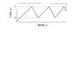
- the upper limit value X1 and the lower limit value X2 are numerical values based on, for example, the office hygiene standard rule based on the Industrial Safety and Health Act, and can be set to 50 ppm and 10 ppm.
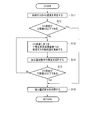
- the carbon monoxide sensor 378 continuously adjusts the carbon monoxide concentration of the processing gas 31 fed through the feed pipe 144 by the blower 144a. Detect (first step S11). A measurement value which is information on the carbon monoxide concentration detected by the carbon monoxide sensor 378 is sent to the control device 379.
- the control device 379 determines whether the measured value is equal to or less than the upper limit value X1 based on the information from the carbon monoxide sensor 378 (second step S12). If the measured value is less than or equal to the upper limit value X1, the process proceeds to a sixth step S16 described later in detail. On the other hand, when the measured value is larger than the upper limit value X1, the amount extracted from the carbon monoxide treatment apparatus 370 to the apparatus main body 171 based on the measured value, that is, the feeding pipe 172 supplies the feed. An amount for extracting a part of the processing gas 31 from the pipe 144 is calculated (third step S13).
- the extraction amount adjusting valve 172a is controlled to adjust the opening degree of the extraction amount adjusting valve 172a (fourth step S14).
- the control device 379 determines whether the measured value is equal to or lower than the lower limit value X2 based on the information from the carbon monoxide sensor 378 (fifth step S15). If the measured value is less than or equal to the lower limit value X2, the process proceeds to a sixth step S16 described later in detail. On the other hand, when the measured value is larger than the lower limit value X2, the process returns to the third step S13, and a part of the processing gas 31 is extracted from the supply pipe 144 by the extraction pipe 172 based on the measured value. Is calculated (third step S13), and based on the calculation result, the extraction amount adjustment valve 172a is controlled to adjust the opening of the extraction amount adjustment valve (fourth step S14). Based on the measured value, it is determined whether the lower limit value X2 or less.
- the control device 379 controls the extraction amount adjusting valve 172a so as not to extract the processing gas 31 from the supply pipe 144 by the extraction pipe 172.
- the extraction amount adjusting valve 172a is fully closed (sixth step S16).
- Such a process is continuously performed until the operation of the modified coal production facility 300 is stopped.
- the concentration of carbon monoxide in the processing gas 31 detected by the carbon monoxide sensor 378 varies between the upper limit value X1 and the lower limit value X2, as shown in FIG. .
- the extraction amount adjusting valve 172a is controlled based on the information of the carbon monoxide concentration in the processing gas 31 detected by the carbon monoxide sensor 378, whereby Even if the used processing gas 33 used and discharged in the apparatus main body 141 is returned to the supply pipe 144 by the circulation pipe 148, the process is supplied into the apparatus main body 141 by the introduction pipe 142. An increase in the carbon monoxide concentration in the gas 31 can be reliably suppressed. Thereby, even if it installs the said coal inactivation processing apparatus 340 in the building which is a closed space, since the raise of the carbon monoxide density
- the modified coal production facility 300 is applied to the modified coal production facility 200, and the carbon monoxide sensor 378 provided in the supply pipe 144 and the extraction amount provided in the extraction pipe 172.
- a modified coal production facility comprising a regulating valve 172a and the control device 379 for controlling the extraction amount regulating valve 172a based on the carbon monoxide concentration information detected by the carbon monoxide sensor 378. Is also possible. Even such a modified coal production facility has the same effects as the modified coal production facility 300.
- the carbon monoxide concentration in the processing gas 31 has been described using the coal inactivation processing device 340 including the control device 379 that controls so as to vary between the upper limit value X1 and the lower limit value X2.
- a coal inactivation treatment apparatus including a control device that controls the carbon monoxide concentration in the treatment gas 31 to be not more than the upper limit value X1.
- a part of the processing gas 31 is extracted from the supply pipe 144 by the extraction pipe 172 and supplied to the apparatus main body 171, and the carbon monoxide concentration of the processing gas 31 is increased in the apparatus main body 171.
- the reduced carbon monoxide concentration-adjusted processing gas 32 is used, and the coal inactivation processing device 140 returns the carbon monoxide concentration-adjusted processing gas 32 to the supply pipe 144 through the discharge pipe 175 and the supply pipe 176.
- 240, and 340 a part of the processing gas 31 or the used processing gas 33 is extracted, and the carbon monoxide concentration of the processing gas 31 and 33 is reduced in the apparatus main body 171.
- the carbon monoxide concentration-adjusted processing gas is used, and the carbon monoxide concentration-adjusted processing gas is used as the supply pipe 144, the introduction pipe 142, the discharge pipe 143, or the circulation pipe. It is also possible to coal deactivation processing apparatus to return to 48.
- the coal inactivation treatment apparatus and the reformed coal production facility using the same according to the present invention increase the concentration of carbon monoxide in the treatment gas, even though the used treatment gas is circulated and reused. Therefore, it can be used extremely beneficially in the industry.
Landscapes
- Chemical & Material Sciences (AREA)
- Oil, Petroleum & Natural Gas (AREA)
- Organic Chemistry (AREA)
- Geochemistry & Mineralogy (AREA)
- Combustion & Propulsion (AREA)
- Engineering & Computer Science (AREA)
- Life Sciences & Earth Sciences (AREA)
- Environmental & Geological Engineering (AREA)
- General Life Sciences & Earth Sciences (AREA)
- Geology (AREA)
- General Chemical & Material Sciences (AREA)
- Physics & Mathematics (AREA)
- Thermal Sciences (AREA)
- Chemical Kinetics & Catalysis (AREA)
- Solid Fuels And Fuel-Associated Substances (AREA)
- Industrial Gases (AREA)
Priority Applications (5)
| Application Number | Priority Date | Filing Date | Title |
|---|---|---|---|
| EP13862453.1A EP2933319A4 (en) | 2012-12-14 | 2013-10-25 | PROCESSING DEVICE FOR CARBENTILIZATION AND EQUIPMENT FOR THE PREPARATION OF MODIFIED COAL THEREWITH |
| AU2013358366A AU2013358366B2 (en) | 2012-12-14 | 2013-10-25 | Coal deactivation processing device and equipment for producing modified coal using same |
| IN10895DEN2014 IN2014DN10895A (enExample) | 2012-12-14 | 2013-10-25 | |
| US14/408,769 US9528065B2 (en) | 2012-12-14 | 2013-10-25 | Coal deactivation processing device and equipment for producing modified coal using same |
| CN201380032598.6A CN104379708B (zh) | 2012-12-14 | 2013-10-25 | 煤非活性化处理装置及利用该装置的改性煤制造设备 |
Applications Claiming Priority (2)
| Application Number | Priority Date | Filing Date | Title |
|---|---|---|---|
| JP2012273339A JP6015933B2 (ja) | 2012-12-14 | 2012-12-14 | 石炭不活性化処理装置およびこれを利用する改質石炭製造設備 |
| JP2012-273339 | 2012-12-14 |
Publications (1)
| Publication Number | Publication Date |
|---|---|
| WO2014091827A1 true WO2014091827A1 (ja) | 2014-06-19 |
Family
ID=50934125
Family Applications (1)
| Application Number | Title | Priority Date | Filing Date |
|---|---|---|---|
| PCT/JP2013/078905 Ceased WO2014091827A1 (ja) | 2012-12-14 | 2013-10-25 | 石炭不活性化処理装置およびこれを利用する改質石炭製造設備 |
Country Status (7)
| Country | Link |
|---|---|
| US (1) | US9528065B2 (enExample) |
| EP (1) | EP2933319A4 (enExample) |
| JP (1) | JP6015933B2 (enExample) |
| CN (1) | CN104379708B (enExample) |
| AU (1) | AU2013358366B2 (enExample) |
| IN (1) | IN2014DN10895A (enExample) |
| WO (1) | WO2014091827A1 (enExample) |
Cited By (4)
| Publication number | Priority date | Publication date | Assignee | Title |
|---|---|---|---|---|
| WO2016143433A1 (ja) * | 2015-03-09 | 2016-09-15 | 三菱重工業株式会社 | 石炭改質プラントおよび改質石炭の製造方法 |
| US10151530B2 (en) | 2015-03-09 | 2018-12-11 | Mitsubishi Heavy Industries Engineering, Ltd. | Coal upgrade plant and method for manufacturing upgraded coal |
| US10188980B2 (en) | 2015-03-09 | 2019-01-29 | Mitsubishi Heavy Industries Engineering, Ltd. | Coal upgrade plant and method for manufacturing upgraded coal |
| US10703976B2 (en) | 2015-03-09 | 2020-07-07 | Mitsubishi Heavy Industries Engineering, Ltd. | Pyrolyzed coal quencher, coal upgrade plant, and method for cooling pyrolyzed coal |
Families Citing this family (5)
| Publication number | Priority date | Publication date | Assignee | Title |
|---|---|---|---|---|
| JP5456073B2 (ja) * | 2012-01-06 | 2014-03-26 | 三菱重工業株式会社 | 石炭不活性化処理装置 |
| JP5971652B2 (ja) | 2012-10-09 | 2016-08-17 | 三菱重工業株式会社 | 石炭不活性化処理装置 |
| JP5536247B1 (ja) | 2013-03-04 | 2014-07-02 | 三菱重工業株式会社 | 石炭不活性化処理装置 |
| CN108019758B (zh) * | 2017-12-08 | 2023-09-19 | 大唐洛阳热电有限责任公司 | 一种热解脱硝工艺中用的热解炉的改装方法 |
| CN108342208B (zh) * | 2018-04-13 | 2023-10-27 | 上海泽玛克敏达机械设备有限公司 | 一种处理生物质燃料的固定床熔渣气化炉及其处理方法 |
Citations (6)
| Publication number | Priority date | Publication date | Assignee | Title |
|---|---|---|---|---|
| JPS5974189A (ja) * | 1982-10-20 | 1984-04-26 | Idemitsu Kosan Co Ltd | 低品位炭の安定化方法 |
| WO1995013868A1 (en) | 1993-11-19 | 1995-05-26 | Mitsui Mining Co., Ltd. | Method of manufacturing active cokes for simultaneous desulfurization and denitration processes |
| JPH11310785A (ja) * | 1998-04-30 | 1999-11-09 | Mitsubishi Heavy Ind Ltd | 石炭改質方法及びその装置 |
| JP2007237011A (ja) | 2006-03-06 | 2007-09-20 | Chugoku Electric Power Co Inc:The | 石炭ミルの火災予防方法及びその装置 |
| JP2012126856A (ja) * | 2010-12-17 | 2012-07-05 | Mitsubishi Heavy Ind Ltd | 石炭不活化処理装置 |
| JP2013139536A (ja) * | 2012-01-06 | 2013-07-18 | Mitsubishi Heavy Ind Ltd | 石炭不活性化処理装置 |
Family Cites Families (8)
| Publication number | Priority date | Publication date | Assignee | Title |
|---|---|---|---|---|
| US4199325A (en) | 1978-11-22 | 1980-04-22 | Atlantic Richfield Company | Inhibiting spontaneous combustion of coal |
| US4401436A (en) * | 1981-12-21 | 1983-08-30 | Atlantic Richfield Company | Process for cooling particulate coal |
| AU552638B2 (en) | 1982-10-20 | 1986-06-12 | Idemitsu Kosan Co. Ltd | Process for modification of coal |
| US5711769A (en) * | 1995-09-08 | 1998-01-27 | Tek-Kol Partnership | Process for passivation of reactive coal char |
| US5601692A (en) | 1995-12-01 | 1997-02-11 | Tek-Kol Partnership | Process for treating noncaking coal to form passivated char |
| US5746787A (en) | 1996-10-28 | 1998-05-05 | Kfx Inc. | Process for treating carbonaceous materials |
| US8470134B2 (en) | 2009-07-14 | 2013-06-25 | C2O Technologies, Llc | Process for treating coal by removing volatile components |
| JP6367518B2 (ja) * | 2012-12-11 | 2018-08-01 | 大日本印刷株式会社 | 採光シート、採光装置、建物、及び採光シートの製造方法 |
-
2012
- 2012-12-14 JP JP2012273339A patent/JP6015933B2/ja not_active Expired - Fee Related
-
2013
- 2013-10-25 AU AU2013358366A patent/AU2013358366B2/en not_active Ceased
- 2013-10-25 US US14/408,769 patent/US9528065B2/en not_active Expired - Fee Related
- 2013-10-25 EP EP13862453.1A patent/EP2933319A4/en not_active Withdrawn
- 2013-10-25 CN CN201380032598.6A patent/CN104379708B/zh not_active Expired - Fee Related
- 2013-10-25 IN IN10895DEN2014 patent/IN2014DN10895A/en unknown
- 2013-10-25 WO PCT/JP2013/078905 patent/WO2014091827A1/ja not_active Ceased
Patent Citations (6)
| Publication number | Priority date | Publication date | Assignee | Title |
|---|---|---|---|---|
| JPS5974189A (ja) * | 1982-10-20 | 1984-04-26 | Idemitsu Kosan Co Ltd | 低品位炭の安定化方法 |
| WO1995013868A1 (en) | 1993-11-19 | 1995-05-26 | Mitsui Mining Co., Ltd. | Method of manufacturing active cokes for simultaneous desulfurization and denitration processes |
| JPH11310785A (ja) * | 1998-04-30 | 1999-11-09 | Mitsubishi Heavy Ind Ltd | 石炭改質方法及びその装置 |
| JP2007237011A (ja) | 2006-03-06 | 2007-09-20 | Chugoku Electric Power Co Inc:The | 石炭ミルの火災予防方法及びその装置 |
| JP2012126856A (ja) * | 2010-12-17 | 2012-07-05 | Mitsubishi Heavy Ind Ltd | 石炭不活化処理装置 |
| JP2013139536A (ja) * | 2012-01-06 | 2013-07-18 | Mitsubishi Heavy Ind Ltd | 石炭不活性化処理装置 |
Non-Patent Citations (1)
| Title |
|---|
| See also references of EP2933319A4 * |
Cited By (6)
| Publication number | Priority date | Publication date | Assignee | Title |
|---|---|---|---|---|
| WO2016143433A1 (ja) * | 2015-03-09 | 2016-09-15 | 三菱重工業株式会社 | 石炭改質プラントおよび改質石炭の製造方法 |
| JPWO2016143433A1 (ja) * | 2015-03-09 | 2017-11-24 | 三菱重工業株式会社 | 石炭改質プラントおよび改質石炭の製造方法 |
| US10151530B2 (en) | 2015-03-09 | 2018-12-11 | Mitsubishi Heavy Industries Engineering, Ltd. | Coal upgrade plant and method for manufacturing upgraded coal |
| US10188980B2 (en) | 2015-03-09 | 2019-01-29 | Mitsubishi Heavy Industries Engineering, Ltd. | Coal upgrade plant and method for manufacturing upgraded coal |
| US10221070B2 (en) | 2015-03-09 | 2019-03-05 | Mitsubishi Heavy Industries Engineering, Ltd. | Coal upgrade plant and method for manufacturing upgraded coal |
| US10703976B2 (en) | 2015-03-09 | 2020-07-07 | Mitsubishi Heavy Industries Engineering, Ltd. | Pyrolyzed coal quencher, coal upgrade plant, and method for cooling pyrolyzed coal |
Also Published As
| Publication number | Publication date |
|---|---|
| US9528065B2 (en) | 2016-12-27 |
| EP2933319A4 (en) | 2016-08-10 |
| AU2013358366A1 (en) | 2015-01-22 |
| EP2933319A1 (en) | 2015-10-21 |
| US20150329793A1 (en) | 2015-11-19 |
| CN104379708B (zh) | 2016-09-21 |
| AU2013358366B2 (en) | 2015-10-01 |
| JP2014118448A (ja) | 2014-06-30 |
| IN2014DN10895A (enExample) | 2015-09-11 |
| CN104379708A (zh) | 2015-02-25 |
| JP6015933B2 (ja) | 2016-10-26 |
Similar Documents
| Publication | Publication Date | Title |
|---|---|---|
| JP6015933B2 (ja) | 石炭不活性化処理装置およびこれを利用する改質石炭製造設備 | |
| KR101727967B1 (ko) | 바이오매스 반탄화 시스템 및 방법 | |
| US10690409B2 (en) | Method for continuously drying bulk goods, in particular wood fibers and/or wood chips | |
| JP5848363B2 (ja) | 高炉設備 | |
| JP5536247B1 (ja) | 石炭不活性化処理装置 | |
| JP2012031335A (ja) | バイオマスの炭化処理装置、及び炭化物の製造方法 | |
| JP5780806B2 (ja) | 汚泥焼却処理システム、及び汚泥焼却処理方法 | |
| JP6015916B2 (ja) | 高炉設備 | |
| JP2876466B2 (ja) | 乾燥システムの燃焼ガス再循環方法 | |
| JP5297066B2 (ja) | 汚泥炭化処理設備における熱分解ガス処理方法及び装置 | |
| EP2855643B1 (en) | Method for torrefaction of biomass with a cyclonic bed reactor | |
| JP5971652B2 (ja) | 石炭不活性化処理装置 | |
| JP2005097063A (ja) | 有機系廃棄物の処理方法 | |
| AU2016230474C1 (en) | Coal upgrade plant and method for manufacturing upgraded coal | |
| CN105883797B (zh) | 一种烟气内循环的氧化炭化系统及方法 | |
| AU2016230473B2 (en) | Coal upgrade plant and method for manufacturing upgraded coal | |
| JP6472042B2 (ja) | 被処理物処理装置及び処理方法 | |
| JP2003190917A (ja) | 焼却灰の処理方法及び処理装置 | |
| JP2007302777A (ja) | 高含水有機物の炭化処理方法及びその装置 | |
| JP6147679B2 (ja) | 石炭乾留装置 | |
| US20160177183A1 (en) | Coal pyrolysis device | |
| JP5714142B2 (ja) | 石炭乾留装置 | |
| EP2451895A1 (en) | An apparatus for thermally treating organic material and method for using the apparatus | |
| ES2071100T3 (es) | Sistema de alimentacion para un horno de recocido de cal. | |
| HK1124380B (en) | Method and its apparatus for processing thermally decomposed gases of carbonization treatment system for highly aqueous organic matter |
Legal Events
| Date | Code | Title | Description |
|---|---|---|---|
| 121 | Ep: the epo has been informed by wipo that ep was designated in this application |
Ref document number: 13862453 Country of ref document: EP Kind code of ref document: A1 |
|
| WWE | Wipo information: entry into national phase |
Ref document number: 2013862453 Country of ref document: EP |
|
| WWE | Wipo information: entry into national phase |
Ref document number: 14408769 Country of ref document: US |
|
| ENP | Entry into the national phase |
Ref document number: 2013358366 Country of ref document: AU Date of ref document: 20131025 Kind code of ref document: A |
|
| WWE | Wipo information: entry into national phase |
Ref document number: IDP00201500577 Country of ref document: ID |
|
| NENP | Non-entry into the national phase |
Ref country code: DE |