WO2014091802A1 - ワイヤレス電力伝送システム - Google Patents
ワイヤレス電力伝送システム Download PDFInfo
- Publication number
- WO2014091802A1 WO2014091802A1 PCT/JP2013/073611 JP2013073611W WO2014091802A1 WO 2014091802 A1 WO2014091802 A1 WO 2014091802A1 JP 2013073611 W JP2013073611 W JP 2013073611W WO 2014091802 A1 WO2014091802 A1 WO 2014091802A1
- Authority
- WO
- WIPO (PCT)
- Prior art keywords
- power
- heat
- power transmission
- power receiving
- passive electrode
- Prior art date
- Legal status (The legal status is an assumption and is not a legal conclusion. Google has not performed a legal analysis and makes no representation as to the accuracy of the status listed.)
- Ceased
Links
Images

Classifications
-
- H—ELECTRICITY
- H04—ELECTRIC COMMUNICATION TECHNIQUE
- H04B—TRANSMISSION
- H04B5/00—Near-field transmission systems, e.g. inductive or capacitive transmission systems
- H04B5/70—Near-field transmission systems, e.g. inductive or capacitive transmission systems specially adapted for specific purposes
- H04B5/79—Near-field transmission systems, e.g. inductive or capacitive transmission systems specially adapted for specific purposes for data transfer in combination with power transfer
-
- H—ELECTRICITY
- H01—ELECTRIC ELEMENTS
- H01M—PROCESSES OR MEANS, e.g. BATTERIES, FOR THE DIRECT CONVERSION OF CHEMICAL ENERGY INTO ELECTRICAL ENERGY
- H01M10/00—Secondary cells; Manufacture thereof
- H01M10/60—Heating or cooling; Temperature control
- H01M10/61—Types of temperature control
- H01M10/613—Cooling or keeping cold
-
- H—ELECTRICITY
- H01—ELECTRIC ELEMENTS
- H01M—PROCESSES OR MEANS, e.g. BATTERIES, FOR THE DIRECT CONVERSION OF CHEMICAL ENERGY INTO ELECTRICAL ENERGY
- H01M10/00—Secondary cells; Manufacture thereof
- H01M10/60—Heating or cooling; Temperature control
- H01M10/65—Means for temperature control structurally associated with the cells
- H01M10/655—Solid structures for heat exchange or heat conduction
- H01M10/6554—Rods or plates
-
- H—ELECTRICITY
- H02—GENERATION; CONVERSION OR DISTRIBUTION OF ELECTRIC POWER
- H02J—ELECTRIC POWER NETWORKS; CIRCUIT ARRANGEMENTS OR SYSTEMS FOR SUPPLYING OR DISTRIBUTING ELECTRIC POWER; SYSTEMS FOR STORING ELECTRIC ENERGY
- H02J50/00—Circuit arrangements or systems for wireless supply or distribution of electric power
- H02J50/005—Mechanical details of housing or structure aiming to accommodate the power transfer means, e.g. mechanical integration of coils, antennas or transducers into emitting or receiving devices
-
- H—ELECTRICITY
- H02—GENERATION; CONVERSION OR DISTRIBUTION OF ELECTRIC POWER
- H02J—ELECTRIC POWER NETWORKS; CIRCUIT ARRANGEMENTS OR SYSTEMS FOR SUPPLYING OR DISTRIBUTING ELECTRIC POWER; SYSTEMS FOR STORING ELECTRIC ENERGY
- H02J50/00—Circuit arrangements or systems for wireless supply or distribution of electric power
- H02J50/05—Circuit arrangements or systems for wireless supply or distribution of electric power using capacitive coupling
-
- H—ELECTRICITY
- H02—GENERATION; CONVERSION OR DISTRIBUTION OF ELECTRIC POWER
- H02J—ELECTRIC POWER NETWORKS; CIRCUIT ARRANGEMENTS OR SYSTEMS FOR SUPPLYING OR DISTRIBUTING ELECTRIC POWER; SYSTEMS FOR STORING ELECTRIC ENERGY
- H02J50/00—Circuit arrangements or systems for wireless supply or distribution of electric power
- H02J50/10—Circuit arrangements or systems for wireless supply or distribution of electric power using inductive coupling
-
- H—ELECTRICITY
- H02—GENERATION; CONVERSION OR DISTRIBUTION OF ELECTRIC POWER
- H02J—ELECTRIC POWER NETWORKS; CIRCUIT ARRANGEMENTS OR SYSTEMS FOR SUPPLYING OR DISTRIBUTING ELECTRIC POWER; SYSTEMS FOR STORING ELECTRIC ENERGY
- H02J50/00—Circuit arrangements or systems for wireless supply or distribution of electric power
- H02J50/70—Circuit arrangements or systems for wireless supply or distribution of electric power involving the reduction of electric, magnetic or electromagnetic leakage fields
-
- H—ELECTRICITY
- H02—GENERATION; CONVERSION OR DISTRIBUTION OF ELECTRIC POWER
- H02J—ELECTRIC POWER NETWORKS; CIRCUIT ARRANGEMENTS OR SYSTEMS FOR SUPPLYING OR DISTRIBUTING ELECTRIC POWER; SYSTEMS FOR STORING ELECTRIC ENERGY
- H02J50/00—Circuit arrangements or systems for wireless supply or distribution of electric power
- H02J50/90—Circuit arrangements or systems for wireless supply or distribution of electric power involving detection or optimisation of position, e.g. alignment
-
- H—ELECTRICITY
- H02—GENERATION; CONVERSION OR DISTRIBUTION OF ELECTRIC POWER
- H02J—ELECTRIC POWER NETWORKS; CIRCUIT ARRANGEMENTS OR SYSTEMS FOR SUPPLYING OR DISTRIBUTING ELECTRIC POWER; SYSTEMS FOR STORING ELECTRIC ENERGY
- H02J7/00—Circuit arrangements for charging or discharging batteries or for supplying loads from batteries
- H02J7/70—Circuit arrangements for charging or discharging batteries or for supplying loads from batteries characterised by the mechanical construction
- H02J7/731—Circuit arrangements for charging or discharging batteries or for supplying loads from batteries characterised by the mechanical construction specially adapted for holding portable devices containing batteries
-
- H—ELECTRICITY
- H04—ELECTRIC COMMUNICATION TECHNIQUE
- H04B—TRANSMISSION
- H04B5/00—Near-field transmission systems, e.g. inductive or capacitive transmission systems
- H04B5/20—Near-field transmission systems, e.g. inductive or capacitive transmission systems characterised by the transmission technique; characterised by the transmission medium
- H04B5/22—Capacitive coupling
-
- H—ELECTRICITY
- H01—ELECTRIC ELEMENTS
- H01M—PROCESSES OR MEANS, e.g. BATTERIES, FOR THE DIRECT CONVERSION OF CHEMICAL ENERGY INTO ELECTRICAL ENERGY
- H01M10/00—Secondary cells; Manufacture thereof
- H01M10/42—Methods or arrangements for servicing or maintenance of secondary cells or secondary half-cells
- H01M10/425—Structural combination with electronic components, e.g. electronic circuits integrated to the outside of the casing
- H01M2010/4271—Battery management systems including electronic circuits, e.g. control of current or voltage to keep battery in healthy state, cell balancing
-
- Y—GENERAL TAGGING OF NEW TECHNOLOGICAL DEVELOPMENTS; GENERAL TAGGING OF CROSS-SECTIONAL TECHNOLOGIES SPANNING OVER SEVERAL SECTIONS OF THE IPC; TECHNICAL SUBJECTS COVERED BY FORMER USPC CROSS-REFERENCE ART COLLECTIONS [XRACs] AND DIGESTS
- Y02—TECHNOLOGIES OR APPLICATIONS FOR MITIGATION OR ADAPTATION AGAINST CLIMATE CHANGE
- Y02E—REDUCTION OF GREENHOUSE GAS [GHG] EMISSIONS, RELATED TO ENERGY GENERATION, TRANSMISSION OR DISTRIBUTION
- Y02E60/00—Enabling technologies; Technologies with a potential or indirect contribution to GHG emissions mitigation
- Y02E60/10—Energy storage using batteries
Definitions
- the present invention relates to a wireless power transmission system that transmits electric power from a power transmission device to a power reception device by electric field coupling.
- Patent Document 1 discloses a non-contact charging device that supplies power from a power transmission device (power supply device) to an electronic device (power receiving device) in a non-contact manner and charges a battery in the electronic device.
- the electronic device and the power transmission device generate heat inside and become high temperature.
- the heat sink is provided in the power transmission apparatus.
- the heat generated when the power receiving coil is operated is transferred to the ceramics, and is transferred from the ceramics to the heat spreader through the heat conductor.
- the heat spreader can release the heat of the power receiving coil to the space in the housing, and thereby can release the heat inside the electronic device and the power transmission device from the housing to the outside.
- the electric power is most required when the device is driven while charging the secondary battery, and accordingly, the heat generation is the largest. If the temperature of the power receiving device becomes high, risk factors such as deterioration of the characteristics of the secondary battery, an increase in the device failure rate, and the possibility of low-temperature burns for the user increase, such being undesirable.
- an object of the present invention is to provide a wireless power transmission system that suppresses a temperature increase of a power receiving device and prevents an increase in size of the power receiving device even in the case of “device driving while charging” in which heat generation is greatest. .
- a wireless power transmission system is a wireless power transmission system that transmits electric power from a power transmission device to a power reception device by electric field coupling.
- the power reception device includes a power reception side active electrode and a power reception side passive connected to a reference potential. When the power is supplied from the electrode, the secondary battery that stores the power supplied from the power receiving side circuit, and the power receiving side circuit, the power is not supplied from the power receiving side circuit.
- a power receiving side circuit including a load that obtains and drives power from the secondary battery, and a circuit that rectifies and smoothes an AC voltage generated between the power receiving side active electrode and the power receiving side passive electrode; and the power receiving side A power receiving side heat dissipating part that dissipates heat from the circuit, and a power receiving side heat conductor that transmits heat generated in the power receiving side circuit during power transmission from the power transmitting device
- the power transmission device includes: a power transmission side active electrode facing the power reception side active electrode with a gap; a power transmission side passive electrode directly in contact with the power reception side passive electrode; A power transmission side circuit that converts the current into an AC voltage and applies the power transmission side active electrode and the power transmission side passive electrode to the power transmission side thermal electrode, and a power transmission side thermal conductor that receives heat directly or indirectly from the power reception side thermal conductor.
- the heat capacity of the power receiving side heat radiating portion is less than the heat capacity required when driving the load while charging the secondary battery, and by transferring heat to the power transmitting
- Examples of the power receiving device include portable electronic devices (smartphones, tablet terminals, etc.), and need to be further downsized. For this reason, it is difficult to secure a space for providing the cooling means in the power receiving device. For this reason, in the above configuration, the heat generated in the power receiving device when the device is driven while charging the secondary battery with the largest heat generation is transferred from the power receiving side heat conductor to the power transmitting device through the power transmitting side heat conductor. Can be conducted. Since the usage mode of driving the device while charging the secondary battery is limited when the power receiving device is placed on the power transmitting device, the heat capacity of the heat sink of the power receiving device is charged to the secondary battery.
- the power receiving side thermal conductor may be a metal, and may be electrically connected to the power receiving side passive electrode.
- a part of the power receiving side passive electrode can be used as the power receiving side thermal conductor.
- the power transmission side thermal conductor may be a metal and may be electrically connected to the power transmission side passive electrode.
- a part of the power transmission side passive electrode can be used as the power transmission side heat conductor.
- At least one of the power receiving side thermal conductor or the power transmitting side thermal conductor is coated with an electrical insulator having a higher thermal conductivity than air, and the power receiving side thermal conductor is connected to the power receiving side via the electrical insulator.
- the structure which receives heat from a heat conductor may be sufficient.
- the power receiving-side heat conductor can be prevented from being exposed from the casing of the power receiving device by covering with an electrical insulator.
- the power-receiving-side thermal conductor is a metal, electrical contact with the outside can be prevented by preventing exposure.
- At least one of the power transmission device or the power reception device may include a close-contact means for bringing the power reception side thermal conductor and the power transmission side thermal conductor into close contact with each other by magnetic force.
- the magnetic force increases the adhesion between the power receiving side thermal conductor and the power transmitting side thermal conductor, thereby improving the thermal conductivity.
- the present invention it is possible to suppress the temperature increase of the power receiving device and to reduce the size of the power receiving device.
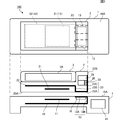
- FIG. 2 is a plan view and a front sectional view of the wireless power transmission system according to the first embodiment.
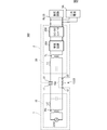
- 1 is a circuit diagram of a wireless power transmission system.
- FIG. 6 is a front sectional view of a wireless power transmission system according to a second embodiment. It is a figure which shows another structural example of a wireless power transmission system.
- FIG. 1 is a plan view and a front sectional view of a wireless power transmission system according to a first embodiment.
- the wireless power transmission system 100 includes a power transmission device 1 and a power reception device 2.
- the power receiving device 2 will be described as a jacket that covers the outer peripheral frame of the tablet-type electronic device 3.
- the electronic device 3 is omitted.
- the power receiving device 2 is placed on the power transmitting device 1.
- a power receiving module 25 is configured in the power receiving device 2. Then, the power receiving module 25 is connected to the electronic device 3 via the connector in the power receiving device 2, and the secondary battery 3 ⁇ / b> A of the electronic device 3 is charged. That is, the power transmission device 1 is a charging stand for the electronic device 3.
- the power receiving device 2 may be a device in which the power receiving device 2 and the electronic device 3 according to the present embodiment are integrated instead of the jacket attached to the electronic device 3.
- a mobile phone a PDA (Personal Digital Assistant), a portable music player, a notebook PC, a digital camera, and the like can be given.
- the casing of the power transmission device 1 has a horizontal placement surface 10A, and the power receiving device 2 is placed on the placement surface 10A.
- the placement surface 10A side (upper side in the drawing) on which the power receiving device 2 is placed is referred to as the upper side.
- the power transmission device 1 includes an active electrode 11 and a passive electrode 12 that are parallel to the placement surface 10A.
- the active electrode 11 is provided on the mounting surface 10 ⁇ / b> A side, and the passive electrode 12 is larger than the active electrode 11 and is provided below the active electrode 11.
- the active electrode 11 and the passive electrode 12 are made of Cu or Ag.
- the power transmission device 1 includes a power transmission module 15.
- the power transmission module 15 converts the input DC voltage into an AC voltage, and boosts the AC voltage.
- the power transmission module 15 applies a boosted AC voltage between the active electrode 11 and the passive electrode 12.
- the power transmission device 1 includes a heat conduction plate 13 for receiving heat from the power reception device 2.
- the heat conductive plate 13 is made of copper or aluminum.
- the heat conduction plate 13 is provided with a flat plate portion 13A parallel to the passive electrode 12, and a connection portion 13B provided perpendicular to the flat plate portion 13A and electrically connecting the flat plate portion 13A and the passive electrode 12. Consists of.
- the flat portion 13A is provided along the placement surface 10A so that one surface is exposed to the placement surface 10A.
- the heat conductive plate 13, particularly the flat portion 13A may be a metal film. Further, the plane portion 13A may not be connected to the passive electrode 12. Further, the heat conductive plate 13 may be a part of the passive electrode 12 instead of a separate member.
- the casing of the power transmission device 1 is made of a material having high thermal conductivity.
- the heat transferred from the power receiving device 2 through the heat conductive plate 23 to the heat conducting plate 13 is also conducted to the passive electrode 12 and radiated to the outside through the casing of the power transmitting device 1.
- a magnet (contact means) 16 is provided on the lower surface of the heat conduction plate 13.
- the magnet 16 is a flexible magnet such as a rubber magnet or a bonded magnet.
- a ferromagnetic body (not shown) is provided in the vicinity of the heat conduction plate 23 (described later) of the power receiving device 2, and the magnet 16 is attracted to the ferromagnetic body, so that the flat portion 13 ⁇ / b> A of the heat conduction plate 13 and heat The conductive plate 23 is in close contact.
- the heat conductive plate 23 is a ferromagnetic material, it is not necessary to provide a ferromagnetic material in the vicinity of the heat conductive plate 23.
- the heat conductive plates 13 and 23 are in close contact with each other by magnetic force, the position where the magnet 16 is provided can be changed as appropriate.
- the magnet 16 when there is a metal in a part of the housing of the power receiving device 2, the magnet 16 is arranged so that the metal portion is attracted, and when the magnet 16 is attracted to the metal of the housing of the power receiving device 2, the heat conduction plate 13. , 23 may be in close contact with each other.
- a magnet may be provided on the power reception device 2 side, or a configuration may be adopted in which neither the power transmission device 1 nor the power reception device 2 is provided with a magnet.
- the power receiving device 2 has a flat back surface 20A, and the power receiving device 2 is placed on the power transmitting device 1 with the back surface 20A facing down so that the back surface 20A is in close contact with the placement surface 10A of the power transmitting device 1.
- the power transmission apparatus 1 and the power receiving apparatus 2 have shown the state slightly separated for convenience of explanation.
- the power receiving device 2 includes an active electrode 21 and a passive electrode 22 parallel to the back surface 20A.
- the active electrode 21 and the passive electrode 22 are made of Cu or Ag.
- the active electrode 21 is provided on the back surface 20A side, and the passive electrode 22 is larger than the active electrode 21, and the active electrode 21 is provided so as to be interposed between the back surface 20A.
- the power receiving device 2 includes a power receiving module 25.
- a power receiving module 25 In the power transmission device 1, when a voltage is applied between the active electrode 11 and the passive electrode 12, an electric field is generated between the opposed active electrodes 11 and 21, and the passive electrodes 12 and 22 are thermally conductive. Direct connections are made through plates 13 and 23.
- the power receiving module 25 rectifies and smoothes the AC voltage generated between the active electrode 21 and the passive electrode 22 by electric field coupling with the power transmission device 1 and converts the AC voltage into a DC voltage.
- the power receiving device 2 outputs the DC voltage to the electronic device 3. Thereby, in the electronic device 3, the secondary battery 3A is charged.
- the power receiving device 2 includes a heat sink (power receiving side heat radiating portion) 28 having a plurality of fins.
- the heat sink 28 has a sufficient heat capacity to dissipate heat generated from the inside of the power receiving device 2 when the power receiving device 2 is driven alone.
- the power receiving device 2 includes a heat conductive plate 23 that directly contacts the heat conductive plate 13 of the power transmitting device 1 and conducts heat to the heat conductive plate 13.
- the heat conductive plate 23 is a metal plate such as copper or aluminum.
- the heat conducting plate 23 is provided perpendicular to the parallel part 23A parallel to the passive electrode 22 and the parallel part 23A, and electrically connects the parallel part 23A and the passive electrode 22 to the parallel part 23A and the parallel part 23A. It is provided with a side surface portion 23 ⁇ / b> C that is provided perpendicular to the power receiving module 25 through the heat transfer member 26.
- the parallel portion 23A is provided along the back surface 20A so that one surface is exposed to the back surface 20A.
- the side surface portion 23C is provided along the side surface 20B orthogonal to the back surface 20A. Heat from the power receiving module 25 is transmitted to the side surface portion 23 ⁇ / b> C through the heat transfer member 26.
- the heat transfer member 26 a heat conductivity is high and an electrically insulating member, for example, high heat conductive rubber and resin, are mentioned.
- the size (thickness) of the heat transfer member 26 is set by the thermal conductivity and thermal resistance of the material of the heat transfer member 26. For example, when the heat transfer member 26 is a high thermal conductive rubber, the casing surface temperature of the electronic device 3 and the power receiving device 2 shown as the power receiving jacket is increased by 85 ° C. as defined in IEC standard 60335-1. It is necessary not to exceed the limit, and based on this, the thickness of the heat transfer member 26 is set.
- the heat conductive plate 23, particularly the flat portion 23A may be a metal film, and the flat portion 23A may not be connected to the passive electrode 22. Further, the heat conductive plate 23 may be a part of the passive electrode 22 instead of a separate member.
- the heat conducting plate 13 and the heat conducting plate 23 are in surface contact.
- the power receiving device 2 is always placed on the power transmitting device 1. Therefore, when the power receiving module 25 of the power receiving device 2 generates heat during power transmission from the power transmitting device 1 to the power receiving device 2, the heat is transferred from the heat conducting plate 23 to the heat conducting plate 13. That is, the heat generated in the power receiving device 2 is conducted to the power transmitting device 1.
- the heat conducting plate 13 and the heat conducting plate 23 are metal, heat conduction is performed efficiently.
- the temperature rise in the power receiving apparatus 2 can be suppressed by releasing the heat of the power receiving apparatus 2 to the power transmitting apparatus 1.
- the heat radiating unit included in the power receiving device 2 can always radiate heat via the power transmission device even if it does not have enough heat capacity to radiate heat generated when driving the device while charging the secondary battery 3A.
- casing surface of the power receiving apparatus 2 can be prevented.
- the heat conducted to the power transmission device 1 is radiated from the entire casing of the power transmission device 1.
- the adhesion between the heat conducting plate 13 and the heat conducting plate 23 is improved by the magnet 16, the heat conduction efficiency from the power receiving device 2 to the power transmitting device 1 is improved, and the heat radiation of the power receiving device 2 can be performed more effectively. .
- the active electrodes 11 and 21 are aligned so as to face each other. Thereby, the user can place the power receiving apparatus 2 on the power transmitting apparatus 1 so that the active electrodes 11 and 21 face each other without being aware of it. As a result, power is not transmitted in a state where the power receiving device 2 is not placed on the power transmitting device 1 in an appropriate positional relationship, and power transmission in an abnormal state is eliminated. Abnormal overheating of the power receiving device 2 is also suppressed.
- FIG. 2 is a circuit diagram of the wireless power transmission system 100.
- the power transmission device 1 is connected to a household outlet of, for example, AC 100V to 240V through an AC adapter (not shown).
- AC 100 V to 240 V is converted into DC 5 V or 12 V by the AC adapter and input to the power transmission device 1.
- the power transmission device 1 operates using the input DC voltage as a power source.
- the power transmission module 15 of the power transmission device 1 includes a high-frequency voltage generation circuit OSC, a step-up transformer TG, and an inductor LG.
- the high frequency voltage generation circuit OSC generates a high frequency voltage of, for example, 100 kHz to several tens of MHz.
- the step-up circuit using the step-up transformer TG and the inductor LG steps up the voltage generated by the high-frequency voltage generation circuit OSC and applies it between the active electrode 11 and the passive electrode 12.
- the power receiving device 2 includes a power receiving module 25, and a load circuit RL corresponding to the electronic device 3 is connected thereto.
- the power receiving module 25 is connected between the active electrode 21 and the passive electrode 22.
- the power reception module 25 includes a step-down circuit using an inductor LL and a step-down transformer TL, a rectifier circuit 251 that converts the stepped-down AC voltage into a DC voltage, and a DC-DC converter 252 that outputs a specified DC voltage to the load circuit RL. It has.
- a resistance r connected between the passive electrode 12 of the power transmission device 1 and the passive electrode 22 of the power reception device 2 is a contact portion of the passive electrodes 12, 22, that is, a heat conduction plate electrically connected to the passive electrode 12. 13 corresponds to a contact resistance configured in a contact portion between the heat conduction plate 23 electrically connected to the passive electrode 22.
- the capacitor Cm connected between the active electrodes 11 and 21 corresponds to a capacitance generated between the active electrodes 11 and 21.
- the passive electrodes 12 and 22 of the power transmission device 1 and the power reception device 2 are directly connected to each other, so that the potential of the power reception device side passive electrode 22 becomes substantially equal to the potential of the power transmission device side passive electrode 12.
- the potential of the power receiving apparatus side passive electrode 22 is stabilized, and ground potential fluctuations and leakage of unnecessary electromagnetic fields are suppressed.
- the degree of coupling increases and high transmission efficiency is obtained.
- the power receiving module 25 has a relatively large calorific value, but these heats are transmitted from the heat conducting plate 23 to the power transmitting device 1 through the heat conducting plate 13. Then, heat from the power receiving module 25 is radiated by the power transmission device 1. Therefore, the temperature rise of the power reception module 25 is suppressed, and problems such as failure of the power reception module 25 or deterioration of characteristics can be avoided.
- the housing of the power receiving device 2 is also made of a material having high thermal conductivity, like the power transmitting device 1.
- the heat of the power reception device 2 is also dissipated through the power transmission device 1 and the housing of the power reception device 2.
- size etc. of the heat conductive plates 13 and 23 can be changed suitably, in order to make heat conduction efficiency high, it is preferable to make the contact area of the heat conductive plates 13 and 23 larger.
- FIG. 3 is a front sectional view of the wireless power transmission system according to the second embodiment.
- the second embodiment is different from the first embodiment in that the heat conduction plate 13 of the power transmission device 1A and the heat conduction plate 23 of the power reception device 2A are not in direct contact.
- symbol is attached and description is abbreviate
- the heat conduction plate 23 included in the power receiving device 2A is not exposed on the back surface 20A of the power receiving device 2A, and is provided on the inner side of the back surface 20A.
- An electrically insulating heat transfer member 27 is provided between the heat conductive plate 23 and the back surface 20A.
- the heat conductive plate 23 is covered with the heat transfer member 27 so as not to be exposed from the casing of the power receiving device 2.
- heat generated from the power receiving module 25 is conducted from the heat conducting plate 23 to the heat conducting plate 13 through the heat transfer member 27.
- the heat conductive plate 23 of the power receiving device 2A is covered with the electrically insulating heat transfer member 27, but the heat conductive plate 13 of the power transmitting device 1A is covered with the electrically insulating heat transfer member. It may be. Also in this case, heat generated from the power receiving module 25 is conducted from the heat conducting plate 23 to the heat conducting plate 13 through the heat transfer member.
- the heat transfer member 27 is a member having high thermal conductivity, such as a metal oxide film or a ceramic plate.
- the thickness of the heat transfer member 27 can be changed as appropriate, as with the heat transfer member 26 according to the first embodiment, the size (thickness) of the heat transfer member 27 is the thermal conductivity of the material of the heat transfer member 27, Set by thermal resistance.
- the casing surface temperature should not exceed 60 ° C. according to IEC standard 60335-1, and thus the thickness of the heat transfer member 27 is set based on this.
- the power transmission device 1 ⁇ / b> A includes a heat sink (heat radiating unit) 18 having a plurality of fins.
- the heat sink 18 radiates heat received from the power receiving device 2A and heat generated from the power transmission module 15 or the like. For this reason, the thermal radiation efficiency in 1 A of power transmission devices can further be improved.
- the heat of the power receiving device is dissipated through the power transmitting device, so that the temperature rise of the power receiving device can be suppressed. For this reason, the heat radiation design in the power receiving device is minimized, and the power receiving device can be downsized.
- the power receiving device is placed (horizontal) on the horizontal placement surface of the power transmitting device.
- the power receiving device is leaned against the power transmitting device to transmit power (vertically placed). It may be.
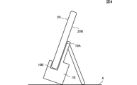
- FIG. 4 is a diagram showing another configuration example of the wireless power transmission system.
- FIG. 4 is a side view showing a state where an electronic device equipped with a jacket corresponding to the power receiving device according to the present invention is placed on the power transmitting device.
- an electronic device hereinafter referred to as a power receiving device 2 ⁇ / b> B
- the power transmission device 1B can be installed such that the placement surface 10A that is in close contact with the back surface 20A of the power reception device 2B is inclined with respect to a horizontal installation surface 4 (for example, on a desk).
- the power transmission device 1B has a groove 10B for placing the power reception device 2B, and the power reception device 2B is inserted into the groove and installed in the power transmission device 1B. Then, power is transmitted from the power transmission device 1B to the power reception device 2B, and heat is conducted from the power reception device 2B to the power transmission device 1B.
- description is abbreviate
- 1, 1A, 1B Power transmission device 2, 2A, 2B—Power reception device 3—Electronic device 3A—Secondary battery 10A—Mounting surface 11—Active electrode (power transmission side active electrode) 12-passive electrode (passive electrode on the power transmission side) 13-Heat conduction plate (power transmission side heat conductor) 15-Power transmission module (power transmission side circuit) 16-magnet (contacting means) 18-Heat sink (heat dissipation part) 20A-Back 20B-Bottom 21-Active electrode (power-receiving-side active electrode) 22-Passive electrode (power-receiving-side active electrode) 23-Thermal conduction plate (Receiving side thermal conductor) 25-Power receiving module (power receiving side circuit) 26, 27-heat transfer member 28-heat sink (power receiving side heat radiation part) 100-Wireless power transmission system
Landscapes
- Engineering & Computer Science (AREA)
- Computer Networks & Wireless Communication (AREA)
- Power Engineering (AREA)
- Electrochemistry (AREA)
- Chemical & Material Sciences (AREA)
- Chemical Kinetics & Catalysis (AREA)
- Manufacturing & Machinery (AREA)
- General Chemical & Material Sciences (AREA)
- Signal Processing (AREA)
- Physics & Mathematics (AREA)
- Electromagnetism (AREA)
- Secondary Cells (AREA)
- Charge And Discharge Circuits For Batteries Or The Like (AREA)
- Cooling Or The Like Of Electrical Apparatus (AREA)
Abstract
Description
図1は実施形態1に係るワイヤレス電力伝送システムの平面図および正面断面図である。
図3は、実施形態2に係るワイヤレス電力伝送システムの正面断面図である。実施形態2では、送電装置1Aの熱伝導板13および受電装置2Aの熱伝導板23が直接接触しない点で実施形態1と相違する。なお、実施形態1と同じ部材については、同じ符号を付し、説明は省略する。
2,2A,2B-受電装置
3-電子機器
3A-二次電池
10A-載置面
11-アクティブ電極(送電側アクティブ電極)
12-パッシブ電極(送電側パッシブ電極)
13-熱伝導板(送電側熱伝導体)
15-送電モジュール(送電側回路)
16-磁石(密着手段)
18-ヒートシンク(放熱部)
20A-背面
20B-底面
21-アクティブ電極(受電側アクティブ電極)
22-パッシブ電極(受電側アクティブ電極)
23-熱伝導板(受電側熱伝導体)
25-受電モジュール(受電側回路)
26,27-伝熱部材
28-ヒートシンク(受電側放熱部)
100-ワイヤレス電力伝送システム
Claims (5)
- 電界結合により、送電装置から受電装置へ電力を伝送するワイヤレス電力伝送システムにおいて、
前記受電装置は、
受電側アクティブ電極と、
基準電位に接続された受電側パッシブ電極と、
前記受電側アクティブ電極と前記受電側パッシブ電極とに生じた交流電圧を整流および平滑する回路を含む受電側回路と、
前記受電側回路から供給される電力を蓄える二次電池と、
前記受電側回路から電力供給されている場合は前記受電側回路から、前記受電側回路から電力が供給されていない場合は前記二次電池から、電力を得て駆動する負荷と、
前記受電側回路からの熱を放熱する受電側放熱部と、
送電装置からの電力伝送時に前記受電側回路に生じる熱が伝わる受電側熱伝導体と、
を備え、
前記送電装置は、
前記受電側アクティブ電極と間隙をおいて対向する送電側アクティブ電極と、
前記受電側パッシブ電極と直接接触し、または間隙をおいて対向する送電側パッシブ電極と、
入力される直流電圧を交流電圧に変換して、前記送電側アクティブ電極および前記送電側パッシブ電極の間に印加する送電側回路と、
直接または間接的に前記受電側熱伝導体から受熱する送電側熱伝導体と、
を備え、
前記受電側放熱部の熱容量は、前記二次電池に充電しながら前記負荷を駆動する際に必要な熱容量に満たないものであって、前記送電側熱伝導体に伝熱させることで、前記二次電池に充電しながら前記負荷を駆動する際に必要な熱容量を確保するようにしたことを特徴とする、ワイヤレス電力伝送システム。 - 前記受電側熱伝導体は金属であり、前記受電側パッシブ電極と電気的に接続されている、請求項1に記載のワイヤレス電力伝送システム。
- 前記送電側熱伝導体は金属であり、前記送電側パッシブ電極と電気的に接続されている、請求項1または2に記載のワイヤレス電力伝送システム。
- 前記受電側熱伝導体または前記送電側熱伝導体の少なくとも一方は空気より高い熱伝導率を有する電気絶縁体により被覆され、
前記受電側熱伝導体は、前記電気絶縁体を介して前記受電側熱伝導体から受熱する、請求項1から3の何れかに記載のワイヤレス電力伝送システム。 - 前記送電装置または前記受電装置の少なくとも一方は、前記受電側熱伝導体と前記送電側熱伝導体とを磁力により密着させる密着手段を備える、請求項1から4の何れかに記載のワイヤレス電力伝送システム。
Priority Applications (3)
| Application Number | Priority Date | Filing Date | Title |
|---|---|---|---|
| CN201390000666.6U CN204497854U (zh) | 2012-12-14 | 2013-09-03 | 无线电力传输系统 |
| JP2014551914A JP5874844B2 (ja) | 2012-12-14 | 2013-09-03 | ワイヤレス電力伝送システム |
| US14/683,559 US20150215007A1 (en) | 2012-12-14 | 2015-04-10 | Wireless power transmission system |
Applications Claiming Priority (2)
| Application Number | Priority Date | Filing Date | Title |
|---|---|---|---|
| JP2012-272926 | 2012-12-14 | ||
| JP2012272926 | 2012-12-14 |
Related Child Applications (1)
| Application Number | Title | Priority Date | Filing Date |
|---|---|---|---|
| US14/683,559 Continuation US20150215007A1 (en) | 2012-12-14 | 2015-04-10 | Wireless power transmission system |
Publications (1)
| Publication Number | Publication Date |
|---|---|
| WO2014091802A1 true WO2014091802A1 (ja) | 2014-06-19 |
Family
ID=50934102
Family Applications (1)
| Application Number | Title | Priority Date | Filing Date |
|---|---|---|---|
| PCT/JP2013/073611 Ceased WO2014091802A1 (ja) | 2012-12-14 | 2013-09-03 | ワイヤレス電力伝送システム |
Country Status (4)
| Country | Link |
|---|---|
| US (1) | US20150215007A1 (ja) |
| JP (1) | JP5874844B2 (ja) |
| CN (1) | CN204497854U (ja) |
| WO (1) | WO2014091802A1 (ja) |
Cited By (1)
| Publication number | Priority date | Publication date | Assignee | Title |
|---|---|---|---|---|
| JP2022181285A (ja) * | 2021-05-26 | 2022-12-08 | 古河電気工業株式会社 | 電力伝送システム、送電装置、受電装置及び机 |
Families Citing this family (4)
| Publication number | Priority date | Publication date | Assignee | Title |
|---|---|---|---|---|
| TWI489761B (zh) * | 2013-03-22 | 2015-06-21 | Univ Nat Taiwan | 整流模組、其電子裝置及其整流方法 |
| US20180351402A1 (en) * | 2015-12-01 | 2018-12-06 | Philips Lighting Holding B.V. | Capacitive power transfer arrangement |
| KR102126773B1 (ko) * | 2018-05-15 | 2020-06-25 | 주식회사 위츠 | 무선 충전용 방열 부재 및 이를 구비하는 전자 기기 |
| CN118648220A (zh) * | 2023-01-12 | 2024-09-13 | 华为数字能源技术有限公司 | 无线充电设备、电子终端设备及无线充电系统 |
Citations (6)
| Publication number | Priority date | Publication date | Assignee | Title |
|---|---|---|---|---|
| JP2000133536A (ja) * | 1998-10-27 | 2000-05-12 | Toyota Autom Loom Works Ltd | 給電カプラ装置、受電側カプラ及び送電側カプラ |
| JP2009005469A (ja) * | 2007-06-20 | 2009-01-08 | Panasonic Electric Works Co Ltd | 非接触型給電装置 |
| JP2010245323A (ja) * | 2009-04-07 | 2010-10-28 | Seiko Epson Corp | コイルユニット及び電子機器 |
| WO2012086411A1 (ja) * | 2010-12-24 | 2012-06-28 | 株式会社村田製作所 | ワイヤレス電力伝送システム、送電装置および受電装置 |
| JP2012130177A (ja) * | 2010-12-16 | 2012-07-05 | Hitachi Maxell Energy Ltd | 充電システム、受電装置を備えた電気機器、及び給電装置を備えた充電器 |
| JP2012213322A (ja) * | 2009-06-25 | 2012-11-01 | Murata Mfg Co Ltd | 電力伝送システム |
Family Cites Families (2)
| Publication number | Priority date | Publication date | Assignee | Title |
|---|---|---|---|---|
| JP3473236B2 (ja) * | 1995-12-26 | 2003-12-02 | トヨタ自動車株式会社 | 電子回路装置 |
| JP4859700B2 (ja) * | 2007-02-20 | 2012-01-25 | セイコーエプソン株式会社 | コイルユニットおよび電子機器 |
-
2013
- 2013-09-03 JP JP2014551914A patent/JP5874844B2/ja active Active
- 2013-09-03 CN CN201390000666.6U patent/CN204497854U/zh not_active Expired - Lifetime
- 2013-09-03 WO PCT/JP2013/073611 patent/WO2014091802A1/ja not_active Ceased
-
2015
- 2015-04-10 US US14/683,559 patent/US20150215007A1/en not_active Abandoned
Patent Citations (6)
| Publication number | Priority date | Publication date | Assignee | Title |
|---|---|---|---|---|
| JP2000133536A (ja) * | 1998-10-27 | 2000-05-12 | Toyota Autom Loom Works Ltd | 給電カプラ装置、受電側カプラ及び送電側カプラ |
| JP2009005469A (ja) * | 2007-06-20 | 2009-01-08 | Panasonic Electric Works Co Ltd | 非接触型給電装置 |
| JP2010245323A (ja) * | 2009-04-07 | 2010-10-28 | Seiko Epson Corp | コイルユニット及び電子機器 |
| JP2012213322A (ja) * | 2009-06-25 | 2012-11-01 | Murata Mfg Co Ltd | 電力伝送システム |
| JP2012130177A (ja) * | 2010-12-16 | 2012-07-05 | Hitachi Maxell Energy Ltd | 充電システム、受電装置を備えた電気機器、及び給電装置を備えた充電器 |
| WO2012086411A1 (ja) * | 2010-12-24 | 2012-06-28 | 株式会社村田製作所 | ワイヤレス電力伝送システム、送電装置および受電装置 |
Cited By (1)
| Publication number | Priority date | Publication date | Assignee | Title |
|---|---|---|---|---|
| JP2022181285A (ja) * | 2021-05-26 | 2022-12-08 | 古河電気工業株式会社 | 電力伝送システム、送電装置、受電装置及び机 |
Also Published As
| Publication number | Publication date |
|---|---|
| US20150215007A1 (en) | 2015-07-30 |
| JP5874844B2 (ja) | 2016-03-02 |
| CN204497854U (zh) | 2015-07-22 |
| JPWO2014091802A1 (ja) | 2017-01-05 |
Similar Documents
| Publication | Publication Date | Title |
|---|---|---|
| US12278501B2 (en) | Wireless power transfer system for simultaneous transfer to multiple devices | |
| JP5168438B2 (ja) | 電力伝送システム、及び受電ジャケット | |
| CN103222153B (zh) | 供电装置以及电力输送系统 | |
| US8330416B2 (en) | Battery module and charging module | |
| JP5874844B2 (ja) | ワイヤレス電力伝送システム | |
| TW201527932A (zh) | 移動終端 | |
| JP6350345B2 (ja) | トランスモジュール及び受電装置 | |
| CN109599917B (zh) | 无线充电装置 | |
| US20220069623A1 (en) | Wireless charging apparatus | |
| WO2014125731A1 (ja) | ワイヤレス電力伝送システム | |
| KR101922022B1 (ko) | 발열 방지 무선 충전 시스템 | |
| US20240243612A1 (en) | Ruggedized Communication for Wireless Power Systems in Multi-Device Environments | |
| JP6379353B2 (ja) | Dc−dcコンバータ | |
| JP2014033546A (ja) | 送電装置及び電力伝送システム | |
| KR20190035068A (ko) | 케이스 및 이를 구비한 무선전력송신기 | |
| CN222356768U (zh) | 一种电源适配器 | |
| CN217692807U (zh) | 无线充电模块、无线充电发射基站及无线充电接收终端 | |
| KR20160139218A (ko) | 디씨-디씨 컨버터 | |
| KR20120055345A (ko) | 전원공급장치 | |
| KR101093142B1 (ko) | 옥외 통신장비용 슬림형 정류기 | |
| EP4645652A1 (en) | Wireless charging device, electronic terminal device, and wireless charging system | |
| CN121124377A (zh) | 充电组件及无线充电设备 | |
| WO2016177057A1 (zh) | 设备外壳、设备、充电座及无线充电方法 |
Legal Events
| Date | Code | Title | Description |
|---|---|---|---|
| WWE | Wipo information: entry into national phase |
Ref document number: 201390000666.6 Country of ref document: CN |
|
| 121 | Ep: the epo has been informed by wipo that ep was designated in this application |
Ref document number: 13861764 Country of ref document: EP Kind code of ref document: A1 |
|
| ENP | Entry into the national phase |
Ref document number: 2014551914 Country of ref document: JP Kind code of ref document: A |
|
| NENP | Non-entry into the national phase |
Ref country code: DE |
|
| 122 | Ep: pct application non-entry in european phase |
Ref document number: 13861764 Country of ref document: EP Kind code of ref document: A1 |