WO2014091772A1 - 直流電力システム、直流電力供給機器、直流機器、電力供給方法、およびプログラム - Google Patents
直流電力システム、直流電力供給機器、直流機器、電力供給方法、およびプログラム Download PDFInfo
- Publication number
- WO2014091772A1 WO2014091772A1 PCT/JP2013/056409 JP2013056409W WO2014091772A1 WO 2014091772 A1 WO2014091772 A1 WO 2014091772A1 JP 2013056409 W JP2013056409 W JP 2013056409W WO 2014091772 A1 WO2014091772 A1 WO 2014091772A1
- Authority
- WO
- WIPO (PCT)
- Prior art keywords
- voltage
- power
- derived
- unit
- necessary
- Prior art date
- Legal status (The legal status is an assumption and is not a legal conclusion. Google has not performed a legal analysis and makes no representation as to the accuracy of the status listed.)
- Ceased
Links
Images




Classifications
-
- G—PHYSICS
- G05—CONTROLLING; REGULATING
- G05F—SYSTEMS FOR REGULATING ELECTRIC OR MAGNETIC VARIABLES
- G05F1/00—Automatic systems in which deviations of an electric quantity from one or more predetermined values are detected at the output of the system and fed back to a device within the system to restore the detected quantity to its predetermined value or values, i.e. retroactive systems
- G05F1/66—Regulating electric power
-
- H—ELECTRICITY
- H02—GENERATION; CONVERSION OR DISTRIBUTION OF ELECTRIC POWER
- H02J—ELECTRIC POWER NETWORKS; CIRCUIT ARRANGEMENTS OR SYSTEMS FOR SUPPLYING OR DISTRIBUTING ELECTRIC POWER; SYSTEMS FOR STORING ELECTRIC ENERGY
- H02J7/00—Circuit arrangements for charging or discharging batteries or for supplying loads from batteries
- H02J7/90—Regulation of charging or discharging current or voltage
- H02J7/96—Regulation of charging or discharging current or voltage in response to battery voltage
-
- H—ELECTRICITY
- H02—GENERATION; CONVERSION OR DISTRIBUTION OF ELECTRIC POWER
- H02J—ELECTRIC POWER NETWORKS; CIRCUIT ARRANGEMENTS OR SYSTEMS FOR SUPPLYING OR DISTRIBUTING ELECTRIC POWER; SYSTEMS FOR STORING ELECTRIC ENERGY
- H02J7/00—Circuit arrangements for charging or discharging batteries or for supplying loads from batteries
- H02J7/855—Circuit arrangements for charging or discharging batteries or for supplying loads from batteries with circuits adapted for supplying loads from the battery
Definitions
- the present disclosure relates to a DC power system, a DC power supply device, a DC device, a power supply method, and a program, and in particular, a DC power system that can recognize and supply a necessary voltage of a DC device with a simple mechanism.
- a DC power supply device, a DC device, a power supply method, and a program are examples of DC power supply devices.
- the DC power system 11 includes a DC power supply device 12 and a DC device 13, and DC power is supplied from the power supply unit 14 to the DC power supply device 12.
- the power conversion unit 22 converts the DC power supplied from the power supply unit 14 via the power input unit 21 into the necessary voltage of the DC device 13, and the DC power passes through the power output unit 23. And supplied to the DC device 13.
- DC power supplied from the DC power supply device 12 is supplied to the main circuit unit 32 via the power input unit 31, and the DC device 13 is driven.
- the power conversion unit 22 can convert the AC power into the necessary voltage of the DC device 13 while performing AC / DC conversion.
- the required DC power voltage may differ depending on the DC device 13, and therefore, it may be necessary to supply a different voltage for each DC device 13.
- the shape and polarity of a device (plug) for connection for each DC device 13 may be different.
- the DC power system 11A includes DC devices 13-1 and 13-2 having different necessary voltages
- the DC power supply device 12A includes the DC devices 13-1 and 13-2.
- DC power can be supplied at the required voltage of each of 13-2. That is, the DC power supply device 12A is provided with a variable power conversion unit 22A and a necessary voltage specifying unit 25 including a rotary switch. Then, the user designates the necessary voltage with respect to the necessary voltage designating unit 25, and selects either the power output unit 23-1 or 23-2 according to the shape and polarity of the plug of the DC device 13.
- the DC power supply device 12A supplies the DC power of the necessary voltage of the DC device 13-1 to the DC device 13-1 via the power output unit 23-1, or via the power output unit 23-2. Then, the DC power of the necessary voltage of the DC device 13-2 is supplied to the DC device 13-2.
- the power conversion unit 22 can AC / DC convert the AC power and convert the AC power into a necessary voltage of the DC device 13.
- a universal AC adapter exists as the power supply device 12A.
- the DC power supply device 12 and the DC device 13 are connected by a communication wire different from the power wire, and the necessary voltage is supplied from the DC device 13 to the DC power supply device 12 using the communication wire.
- a mechanism for sending it may not be preferable to physically increase the wiring in this way.
- Patent Document 1 discloses a mechanism for transmitting a necessary voltage from the DC device 13 to the DC power supply device 12 by superimposing the DC power using a power wiring.
- the DC device includes means for transmitting a signal by superimposing a signal on DC power
- the DC power supply device includes means for receiving a signal superimposed on DC power. It is necessary and the mechanism becomes complicated.
- the present disclosure has been made in view of such a situation, and enables a necessary voltage of a DC device to be recognized and supplied with a simple mechanism.
- a DC power system is a DC power system including a DC device that requires DC power and a DC power supply device that supplies DC power to the DC device, and the DC power supply device includes: Instructing the power conversion unit that can output DC power by changing the output voltage to supply DC power to the DC device while changing the voltage according to a predetermined method, A derived voltage search unit for retrieving a derived voltage defined for deriving a necessary voltage necessary for driving; a necessary voltage deriving unit for deriving the necessary voltage from the derived voltage specified by the derived voltage search unit; A necessary voltage designating unit that instructs the power conversion unit to supply the direct current power of the necessary voltage derived by the necessary voltage deriving unit to the DC device; DC device, the voltage of the DC power supplied from the DC power supply device, allowing to below the derived voltage, having the derived voltage cutting unit for cutting the input of the DC power when it exceeds the derived voltage.
- a DC power supply device is a DC power supply device that supplies DC power to a DC device that requires DC power, and can output DC power by changing an output voltage.
- the conversion unit is instructed to supply DC power to the DC device while changing the voltage according to a predetermined method, and a derived voltage defined for deriving a necessary voltage necessary for driving the DC device is obtained.
- a derived voltage search unit for searching, a necessary voltage deriving unit for deriving the necessary voltage from the derived voltage specified by the derived voltage searching unit, and the power conversion unit for the necessary voltage deriving unit A necessary voltage designating unit for instructing to supply the DC power of the required voltage to the DC device.
- the voltage of the DC power supplied from the DC power supply device is Deriving a voltage is allowed to below, the input DC power is disconnected when it exceeds the derived voltage.
- the DC device is a DC device that requires DC power, and the DC power supply device that supplies DC power to the DC device changes the output voltage and outputs DC power. Defined to derive a necessary voltage for driving the DC device by instructing the power conversion unit capable of supplying DC power to the DC device while changing the voltage according to a predetermined method.
- Derived voltage search unit for searching for derived voltage; Necessary voltage derivation unit for deriving the necessary voltage from the derived voltage specified by the derived voltage search unit; Derived by the necessary voltage deriving unit for the power conversion unit And a necessary voltage designating unit for instructing to supply the direct current power of the necessary voltage to the direct current device, and the direct current power voltage supplied from the direct current power supply device is Allowed to a voltage below comprises deriving voltage cutting unit for cutting the input of the DC power when it exceeds the derived voltage.
- a power supply method or program includes a DC power system including a DC device that requires DC power and a DC power supply device that supplies DC power to the DC device, or the A program for causing a computer to execute processing in a DC power system, wherein the voltage is changed according to a predetermined method for a power conversion unit that can output DC power by changing the output voltage in the DC power supply device Instructing the DC device to supply DC power while searching for a derived voltage defined for deriving a necessary voltage necessary for driving the DC device, and determining the necessary voltage from the identified derived voltage.
- Deriving voltage and instructing the power conversion unit to supply the derived DC power of the necessary voltage to the DC device A step of allowing the voltage of the DC power supplied from the DC power supply device to be less than or equal to the derived voltage and cutting off the input of the DC power when the voltage exceeds the derived voltage.
- the DC power is supplied to the DC device while changing the voltage according to a predetermined method with respect to the power converter that can output the DC power by changing the output voltage. Instructed to supply, the derived voltage defined to derive the necessary voltage for driving the DC equipment is searched, the necessary voltage is derived from the identified derived voltage, and derived to the power converter It is instructed to supply DC power of the required voltage to the DC equipment.
- the voltage of the DC power supplied from the DC power supply device is allowed to be equal to or lower than the derived voltage, and the input of the DC power is cut when the derived voltage is exceeded.
- the required voltage of the DC device can be recognized and supplied with a simple mechanism.
- FIG. 2 is a functional block diagram illustrating a configuration example of the first embodiment of the DC power system to which the present technology is applied.
- system represents the entire apparatus including a plurality of apparatuses.
- the DC power system 41 includes a DC power supply device 42 and a DC device 43, and power is supplied from the power supply unit 44 to the DC power supply device 42.
- the power supply unit 44 supplies DC power.
- the AC power is AC / DC in the DC power supply device 42. It is assumed that DC power is supplied to the DC device 43 after conversion.
- the DC power supply device 42 specifies a necessary voltage necessary for driving the DC device 43 and supplies the DC power of the necessary voltage to the DC device 43.
- the DC power supply device 42 includes a power input unit 51, a power conversion unit 52, a power output unit 53, a derived voltage search function 54, a necessary voltage derivation function 55, and a necessary voltage designation function 56.
- the power input unit 51 includes a connector to which wiring for inputting the DC power supplied from the power supply unit 44 to the DC power supply device 42 is connected, and converts the DC power from the power supply unit 44 into power. To the unit 52.
- the power conversion unit 52 is a variable conversion unit that can change the voltage to be output.
- the power conversion unit 52 converts the DC power of a predetermined voltage input through the power input unit 51 into a derived voltage search function 54 or a necessary voltage designation function.
- the voltage is converted into a voltage designated by 56 and output.
- the power output unit 53 is configured to include a connector to which a wiring for supplying DC power output from the DC power supply device 42 to the DC device 43 is connected, and can be electrically connected to an external device.
- the DC power output from the unit 52 is supplied to the DC device 43 via the power output unit 53.
- the power output unit 53 can measure the current of the DC power supplied to the DC device 43, and when the DC power input is cut off in the DC device 43 as will be described later, the current stops. It detects by doing. Then, the power output unit 53 notifies the derived voltage search function 54 of the timing when the input of the DC power is cut off in the DC device 43.
- the derived voltage search function 54 changes the output voltage of the power converter 52, and based on the timing notified from the power output unit 53 that the DC power input has been cut off in the DC device 43, the derived voltage search function 54 It has a function of retrieving a derived voltage Vx defined to derive a voltage.
- the necessary voltage deriving function 55 is set with a deriving function f (Vx) for calculating the necessary voltage of the DC device 43, and the necessary voltage deriving function 55 is derived by the derived voltage Vx searched by the derived voltage searching function 54. Is substituted into the derivation function f (Vx), and the necessary voltage of the DC device 43 is derived.
- the required voltage specifying function 56 has a function of specifying the required voltage of the DC device 43 derived by the necessary voltage deriving function 55 to the power conversion unit 52.
- the necessary voltage designating function 56 designates the necessary voltage of the DC device 43 to the power conversion unit 52, whereby the necessary voltage DC power is output from the power conversion unit 52.
- the DC device 43 includes a power input unit 61, a main circuit unit 62, and a derived voltage cutting function 63, and operates with DC power of a necessary voltage that is uniquely determined by the specifications.
- the power input unit 61 supplies the DC power to the main circuit unit 62. Further, the power input unit 61 cuts the input of DC power in accordance with an instruction from the derived voltage cutting function 63.
- the main circuit unit 62 is driven by supplying DC power of a necessary voltage via the power input unit 61, and executes various processes for operating the DC device 43.
- the derived voltage disconnection function 63 allows the voltage input to the power input unit 61 to be less than or equal to the derived voltage Vx, and when the voltage input to the power input unit 61 exceeds the derived voltage Vx, It has a function of instructing to cut off the input of DC power.
- the DC power supply device 42 and the DC device 43 are configured.
- the DC power supply device 42 obtains and supplies the necessary voltage of the DC device 43.
- the DC device 43 can be driven by DC power of a necessary voltage.
- the derived voltage search function 54 increases the output voltage stepwise from 0 V to supply DC power to the DC device 43.
- the power conversion unit 52 is instructed to do so.
- the voltage of the DC power supplied from the DC power supply device 42 to the DC device 43 increases stepwise from 0V.
- the derived voltage cutting function 63 causes the power input unit 61 to disconnect the input of DC power in the DC device 43.
- the power output unit 53 detects the disconnection of the DC power input in the DC device 43 and notifies the derived voltage search function 54 of the disconnection. Then, the derived voltage search function 54 specifies the voltage immediately before the input of DC power is disconnected as the derived voltage Vx, and notifies the necessary voltage deriving function 55 of the derived voltage Vx. In accordance with this, the necessary voltage derivation function 55 substitutes the notified derivation voltage Vx into the derivation function f (Vx) to derive the necessary voltage of the DC device 43 and notifies the necessary voltage designation function 56 of it. Then, the necessary voltage designation function 56 designates the notified necessary voltage of the DC device 43 to the power conversion unit 52.
- the DC power supply device 42 is configured in this way, and can recognize the required voltage of the DC device 43 with a simpler mechanism and supply the DC power of the required voltage to the DC device 43. Further, in the configuration in which the user designates the necessary voltage, it is assumed that a DC current having a different voltage is supplied to the DC device 43 by mistake, but such an error occurs in the DC power supply device 42. This can be prevented and the direct current of the required voltage can be reliably supplied to the direct current device 43.
- the DC power supply device 42 and the DC device 43 do not need to include means for performing communication by superimposing on DC power, so that the apparatus is complicated. Can be avoided. Thereby, the cost required for development and manufacture can be suppressed, and the spread of the DC power system 41 can be promoted.
- Patent Document 1 discloses a method of increasing the voltage stepwise from 0 V to the required voltage.
- DC power is supplied to a DC device by supplying DC power of an intermediate voltage.
- a voltage range in which the necessary voltage and the derived voltage Vx do not overlap can be defined by appropriately setting the necessary voltage range and the derivation function f (Vx).
- the direct current power of the intermediate voltage is supplied to the direct current device 43 by outputting the direct current power of the necessary voltage. Is avoided. Therefore, it is possible to prevent a malfunction or failure of the DC device 43 from occurring.
- the necessary voltage range and the derived function f (Vx) in a range that does not overlap, it is possible to avoid misidentifying the high voltage range as the derived voltage Vx.
- the configuration of the DC power supply device 42 and the DC device 43 is not greatly changed from the conventional one, with a very simple mechanism, and with a mechanism excellent in versatility and expansibility, It is possible to recognize the necessary voltage of the DC device 43 and supply DC power of the necessary voltage. Furthermore, customization such as improving accuracy and performance, reducing costs, and narrowing allowable voltage can be flexibly selected in accordance with product characteristics.
- FIG. 3 shows a structural block diagram for realizing the DC power system 41 in the functional block shown in FIG.
- the same reference numerals are given to the blocks common to the configuration shown in FIG. 2, and detailed description thereof is omitted.
- the DC power supply device 42 includes a control unit 71 including a CPU (Central Processing Unit), a memory, and the like.
- the CPU executes the program stored in the memory, thereby realizing the functions of the derived voltage search function 54, the necessary voltage derivation function 55, and the necessary voltage designation function 56.
- the power input unit 61 can be built in a power input device 45 added outside the DC device 43, and the power input unit 61 includes a power limiting circuit 72 that realizes a derived voltage disconnection function 63. Is done. In this way, the DC device 43 is connected to the power input device 45, and DC power is supplied from the DC power supply device 42 via the power input device 45.
- the DC power system 41 recognizes the necessary voltage of the DC device 43 with a simple configuration in which the power limiting circuit 72 is added and a simple algorithm executed by the control unit 71, and the DC power of the necessary voltage. Can be supplied to the DC device 43.
- FIG. 4 is a functional block diagram showing a configuration example of the second embodiment of the DC power system to which the present technology is applied.
- the DC power system 41A shown in FIG. 4 includes a DC power supply device 42 and a DC device 43A.
- the DC power supply device 42 is similar to the DC power supply device 42 of FIG. 2 in that the power input unit 51, the power conversion unit 52, the power output unit 53, the derived voltage search function 54, the necessary voltage derivation function 55, and the necessary A voltage specifying function 56 is provided.
- the DC device 43A is configured to include a power input unit 61, a main circuit unit 62, and a derived voltage cutting function 63, similarly to the DC device 43 of FIG.
- the DC device 43A is configured differently from the DC device 43 of FIG.
- the permissible voltage transmission function 64 allows the DC power to pass through the power input unit 61 only when the voltage of the DC power input to the power input unit 61 is a permissible voltage that allows the main circuit unit 62 to operate.
- the allowable voltage is a voltage in a range that includes the necessary voltage of the DC device 43 and that is minimally allowable by the DC device 43.
- the voltage in a predetermined range For example, the allowable voltage is not determined in the specification of the DC device 43, but an allowable range may be specified as a design error, and the allowable voltage may be 0 V. In that case, the DC power supply device 42 (or The power conversion unit 52, the power output unit 53, and the derived voltage search function 54) must be highly accurate.
- FIG. 5 shows a structural block diagram for realizing the DC power system 41A in the functional block shown in FIG.
- the same reference numerals are given to the blocks common to the configurations shown in FIGS. 3 and 4, and the detailed description thereof is omitted.
- each function of a derived voltage search function 54, a necessary voltage derivation function 55, and a necessary voltage designation function 56 is realized in the control unit 71.
- the power input unit 61A can be built in a power input device 45A added outside the DC device 43.
- the power input unit 61A includes a power limiting circuit 72 that realizes a derived voltage disconnection function 63, and an allowable voltage. And a power limiting circuit 73 for realizing the transmission function 64. In this way, the DC device 43 is connected to the power input device 45, and DC power is supplied from the DC power supply device 42 via the power input device 45.
- the DC power system 41A recognizes the necessary voltage of the DC device 43 with a simple configuration in which the power limiting circuit 72 and the power limiting circuit 73 are added and a simple algorithm executed by the control unit 71.
- the DC power of the necessary voltage can be supplied to the DC device 43.
- the power input unit 61 ⁇ / b> A may be built in the DC device 43. That is, as in a modification of the DC power system 41A shown in FIG. 6, the DC device 43 'of the DC power system 41A' can include the power input unit 61A and the main circuit unit 62.
- the power limiting circuit 73 that realizes the power limiting circuit 72 is connected in series to the DC power supply device 42 and the main circuit unit 62 to realize the power limiting circuit 73.
- One end of the limit circuit 72 is connected to the wiring between the DC power supply device 42 and the power limit circuit 73, and the other end of the DC power supply device 42 is grounded.
- the power limiting circuit 72 realizes the derived voltage cutting function 63, and in the example of FIG. 7, 2.0V is set as the derived voltage Vx. That is, the power limiting circuit 72 transmits DC power having a voltage from 0 V to 2.0 V, and cuts transmission of DC power when the voltage input to the power input unit 61 exceeds 2.0 V.
- the power limiting circuit 73 realizes a permissible voltage transmission function 64.
- the necessary voltage of the DC device 43 is 10.0V
- the voltage allowed for the operation of the DC device 43A is 9.5V.
- the necessary voltage is derived to be 10.0V according to the derivation function f (Vx).
- the DC power is supplied to the main circuit unit 62 through the power limiting circuit 73.
- the power input unit 61A includes the power limiting circuit 73, so that the DC power having a voltage greatly different from the required voltage is prevented from being supplied to the main circuit unit 62, and the DC power having such a voltage is used. Can be avoided from being malfunctioned or caused by being supplied to the main circuit unit 62.
- the derived voltage search function 54 uses a method of searching for the derived voltage Vx by gradually increasing the voltage output from the power conversion unit 52 in a certain step (hereinafter referred to as a fixed step method).
- the necessary voltage of the DC device 43 is 10.0 V
- the derived voltage Vx at which the derived voltage cutting function 63 cuts off the input of power is 2.0 V
- the necessary voltage deriving function 55 has f (Vx) as the derived function f (Vx).
- Vx ⁇ 5 is set.
- the range of the required voltage of the DC device 43 is in the range of 5.0V to 24.0V, and the DC device 43 may operate with a voltage within this range.
- the derived voltage search function 54 instructs the power converter 52 to output DC power having a voltage of, for example, 1.0 V as an initial voltage. .
- step S12 the derived voltage search function 54 determines whether or not the DC power input to the DC device 43 is disconnected. For example, when the power output unit 53 notifies that the current output to the DC device 43 has stopped, the derived voltage search function 54 determines that the power input to the DC device 43 has been disconnected, and there is no notification. In this case, it is determined that the power input to the DC device 43 is not disconnected.
- step S12 when the derived voltage search function 54 determines that the power input to the DC device 43 is not disconnected, the process proceeds to step S13.
- step S13 the derived voltage search function 54 specifies that the voltage of the DC power output to the power converter 52 is increased by 0.2 V, the process returns to step S12, and the same process is repeated thereafter.
- the DC device 43 The derived voltage cutting function 63 causes the power input unit 61 to cut the input of DC power. That is, the input of DC power is cut by the power limiting circuit 72 that implements the derived voltage cutting function 63.
- the power output unit 53 detects that the current output to the DC device 43 has stopped and notifies the derived voltage search function 54, the derived voltage search function 54 is input to the DC device 43 in step S12. It is determined that the DC power has been disconnected, and the process proceeds to step S14.
- step S14 the derived voltage search function 54 specifies the voltage immediately before the power supply is cut off, that is, 2.0 V as the derived voltage Vx, and notifies the necessary voltage derivation function 55 of it.
- the power conversion unit 52 outputs DC power having a voltage of 10.0V.
- the DC voltage having a voltage of 10.0V is transmitted through the power input unit 61 by the allowable voltage transmission function 64, and the required voltage
- the direct current is supplied to the main circuit unit 62, and the main circuit unit 62 can operate normally.
- the derived voltage search function 54 may search the derived voltage Vx using a binary search method in addition to searching the derived voltage Vx using the above-described constant step method.
- a voltage that divides the voltage range including the derived voltage Vx into two is sequentially output from the power converter 52, and the derived voltage Vx is searched by narrowing the voltage range including the derived voltage Vx.
- the derived voltage search function 54 first outputs DC power at a derived voltage (2.9 V) for deriving 14.5 V, which is the middle of the required voltage range of 5 V to 24 V. This is specified for the power conversion unit 52. Thereafter, the derived voltage search function 54 determines the output voltage according to the binary search method and designates it to the power converter 52, and determines the upper limit voltage at which the DC power input is not cut off as the derived voltage Vx in the DC device 43. can do. As described above, by using the binary search method, it is possible to reduce the number of times the power conversion unit 52 changes the voltage and outputs the voltage until the derived voltage Vx is identified, and the derived voltage Vx is identified at a higher speed. be able to.
- the derived voltage search function 54 can employ various search algorithms in addition to the fixed-step method and the binary search method. And the precision which pinpoints the derivation voltage Vx can be improved by using a several search algorithm together, or performing the same search algorithm in multiple times.
- the derived voltage search function 54 holds the necessary voltage of the DC device 43 that has supplied DC power in the past, and the DC that is currently connected as an object to supply DC power from these required voltages.
- a learning function for specifying a predetermined voltage when starting a search for a derived voltage with respect to the device 43 may be provided. Then, the derived voltage search function 54 can start searching for the derived voltage of the DC device 43 from a predetermined voltage specified by learning.
- the derived voltage search function 54 may hold the necessary voltages of the DC devices 43 that have been connected until the previous time, and start the search algorithm with the average value of the necessary voltages as a predetermined voltage. .
- the derived voltage search function 54 sets the necessary voltage of the DC device 43 with the largest number of connections among the predetermined number of DC devices 43 connected most recently as a predetermined voltage as the first target, and performs a search algorithm. You may start.
- the DC power supply device 42 is installed so as to be embedded in the wall of the facility.
- the terminal of the cable for supplying DC power to the DC device 43 is used so as to be inserted into the connector of the power output unit 53 arranged on the wall surface.
- a power output unit 53 is provided on a panel 81 installed on a wall surface, like a general household outlet.
- FIG. 9 shows an example in which two power output units 53-1 and 53-2 are provided.
- the display units 82-1 and 82-2 devices that do not need to consume power when holding display contents are used. For example, electronic paper, display content holding liquid crystal, or the like is preferably used.
- the user can recognize the necessary voltage output from the power output units 53-1 and 53-2.
- a display unit for displaying a necessary voltage or a derived voltage of the DC device 43 is provided near the connector of the power input unit 61 arranged in the casing of the DC device 43. It may be provided. Thereby, the user can recognize the necessary voltage or derived voltage of the DC device 43.
- the power output unit 53 of the DC power supply device 42 can include a connection detection unit that detects the connection of the DC device 43.
- the power output unit 53 includes a connector 93, a switch 94, and an interlocking mechanism 95.
- the connector 93 is a concave connection part into which the terminal 92 of the cable 91 for supplying DC power to the DC device 43 can be inserted.
- the switch 94 detects the connection of the DC device 43 and is turned on when the DC device 43 is connected. When the switch 94 is in the OFF state, the output of the DC power by the power conversion unit 52 is stopped, and when the switch 94 transitions from the OFF state to the ON state, the DC power supply device 42 has the necessary voltage of the DC device 43. The process for obtaining and supplying the data (FIG. 8) is started.
- the interlocking mechanism 95 is a mechanism that turns on the switch 94 in conjunction with the insertion of the terminal 92 of the cable 91 into the connector 93.
- the power output unit 53 configured as described above, as shown in FIG. 10A, when the terminal 92 of the cable 91 is disconnected from the connector 93, the interlocking mechanism 95 is housed inside the connector 93 and the switch 94. Is turned off. Thereby, the power output unit 53 determines that the DC device 43 is not connected, and the output of the DC power by the power conversion unit 52 is stopped.
- the power output unit 53 determines that the DC device 43 is connected, the DC power supply device 42 performs processing for obtaining and supplying the necessary voltage of the DC device 43, and the DC conversion is performed from the power conversion unit 52. Electric power is output.
- the power output unit 53 includes the connection detection unit that detects the connection of the DC device 43, so that the DC power of the necessary voltage is reliably supplied to the DC device 43 only when the DC device 43 is connected. can do.
- a linear function is used as the derivation function f (Vx).
- the derivation function f (Vx) can be defined as a function, a function other than the linear function may be used.
- the pitch for each 1V is widened in the high voltage region, whereas the pitch for each 1V can be narrowed in the low voltage region.
- the required voltage is 3.3V or 7.2V in the low voltage range, whereas the high voltage range is effective when a large number of products such as 16V or 19V occupy 1V pitch.
- the derivation function f (Vx) may be determined based on electrical characteristics (technical restrictions). In the case of simple conversion using a linear function for the derived function f (Vx), the influence of the voltage drop can be eliminated.
- the processes described with reference to the flowcharts described above do not necessarily have to be processed in chronological order in the order described in the flowcharts, but are performed in parallel or individually (for example, parallel processes or objects). Processing).
- the program may be processed by one CPU, or may be distributedly processed by a plurality of CPUs.
- the above-described series of processing can be executed by hardware or can be executed by software.
- a program constituting the software executes various functions by installing a computer incorporated in dedicated hardware or various programs.
- the program is installed in a general-purpose computer capable of recording from a program recording medium on which the program is recorded.
Landscapes
- Engineering & Computer Science (AREA)
- Power Engineering (AREA)
- Physics & Mathematics (AREA)
- Electromagnetism (AREA)
- General Physics & Mathematics (AREA)
- Radar, Positioning & Navigation (AREA)
- Automation & Control Theory (AREA)
- Direct Current Feeding And Distribution (AREA)
Abstract
直流電力供給機器は、出力する電圧を変更して直流電力を出力することができる電力変換部に対し、所定の方式に従って電圧を変更させながら直流機器に直流電力を供給するように指示して、直流機器の駆動に必要な必要電圧を導出するために定義された導出電圧を検索する導出電圧検索部と、導出電圧検索部により特定された導出電圧から必要電圧を導出する必要電圧導出部と、電力変換部に対し、必要電圧導出部により導出された必要電圧の直流電力を直流機器に供給するように指示する必要電圧指定部とを有する。また、直流機器は、直流電力供給機器から供給される直流電力の電圧が、導出電圧以下まで許容し、導出電圧を超えたときに直流電力の入力を切断する導出電圧切断部を有する。本技術は、例えば、DCバスを介して直流電力を供給する直流電力システムに適用でき、直流機器の必要電圧を簡易な仕組みで認識して供給できる。
Description
本開示は、直流電力システム、直流電力供給機器、直流機器、電力供給方法、およびプログラムに関し、特に、直流機器の必要電圧を簡易な仕組みで認識して供給することができるようにした直流電力システム、直流電力供給機器、直流機器、電力供給方法、およびプログラムに関する。
近年、電力系統を介して供給される交流電力をAC/DC(Alternating current / Direct current)変換した直流電力や、太陽電池などで発電された直流電力、バッテリから出力される直流電力などを、DCバスを介して、直流電力を必要とする機器(以下、直流機器と称する)に供給する直流電力システムが提案されている。このような直流電力システムにおいて、DCバスに接続されている電力供給部から出力される直流電力の電圧が、直流機器の駆動に必要な電圧(以下、必要電圧と称する)と異なるとき、直流機器の必要電圧となるように電圧を変換して供給する直流電力供給機器が使用される。
例えば、図1のAに示すように、直流電力システム11は、直流電力供給機器12および直流機器13から構成され、電力供給部14から直流電力供給機器12に直流電力が供給される。直流電力供給機器12では、電力変換部22が、電力供給部14から電力入力部21を介して供給される直流電力を直流機器13の必要電圧に変換し、その直流電力が電力出力部23を介して直流機器13に供給される。直流機器13では、直流電力供給機器12から供給される直流電力が電力入力部31を介して主回路部32に供給され、直流機器13が駆動する。
なお、電力供給部14が交流電力を供給する場合には、電力変換部22は、その交流電力をAC/DC変換するとともに、直流機器13の必要電圧に変換することができる。
また、直流電力システム11において、直流機器13によって必要とする直流電力の電圧が異なることがあるため、直流機器13ごとに異なる電圧を供給することが必要となることがある。また、直流機器13ごとに接続するための装置(プラグ)の形状や極性が異なることがある。
例えば、図1のBに示すように、直流電力システム11Aは、それぞれ必要電圧の異なる直流機器13-1および13-2を有しており、直流電力供給機器12Aは、直流機器13-1および13-2それぞれの必要電圧で直流電力を供給することができる。即ち、直流電力供給機器12Aは、可変式の電力変換部22Aと、ロータリースイッチなどから構成される必要電圧指定部25とを設けている。そして、利用者は、必要電圧指定部25に対して必要電圧を指定し、直流機器13のプラグの形状や極性に応じて電力出力部23-1または23-2のいずれか一方を選択する。この選択に従って、直流電力供給機器12Aは、電力出力部23-1を介して直流機器13-1の必要電圧の直流電力を直流機器13-1に供給したり、電力出力部23-2を介して直流機器13-2の必要電圧の直流電力を直流機器13-2に供給したりする。
なお、電力供給部14が交流電力を供給する場合には、電力変換部22は、その交流電力をAC/DC変換するとともに、直流機器13の必要電圧に変換することができ、このような直流電力供給機器12Aとして、ユニバーサルACアダプタが存在する。
ところで、直流電力供給機器12Aのように、利用者が必要電圧を指定したり電力出力部23を選択したりする方法では、利用者が必要電圧の指定を間違えたり、プラグの極性の違いに気づかずに電力出力部23の選択を間違えてしまうことが想定される。このような利用者の間違いを回避するために、直流電力供給機器12Aが直流機器13-1および13-2の必要電圧を認識する仕組みが必要となる。
例えば、直流電力供給機器12および直流機器13を、電力用の配線とは別の通信用の配線により接続し、その通信用の配線を用いて、直流機器13から直流電力供給機器12に必要電圧を送信する仕組みが考えられる。しかしながら、このように物理的に配線を増やすことは好ましくないことがある。
そこで、例えば、特許文献1には、電力用の配線を利用して、直流電力に重畳して直流機器13から直流電力供給機器12に必要電圧を送信する仕組みが開示されている。
しかしながら、特許文献1に開示されている仕組みでは、直流機器が直流電力に信号を重畳させて信号を送信する手段を備え、直流電力供給機器が直流電力に重畳された信号を受信する手段を備える必要があり、仕組みが複雑化することになる。
本開示は、このような状況に鑑みてなされたものであり、直流機器の必要電圧を簡易な仕組みで認識して供給することができるようにするものである。
本開示の一側面の直流電力システムは、直流電力を必要とする直流機器、および、前記直流機器に直流電力を供給する直流電力供給機器を備える直流電力システムであって、前記直流電力供給機器は、出力する電圧を変更して直流電力を出力することができる電力変換部に対し、所定の方式に従って電圧を変更させながら前記直流機器に直流電力を供給するように指示して、前記直流機器の駆動に必要な必要電圧を導出するために定義された導出電圧を検索する導出電圧検索部と、前記導出電圧検索部により特定された前記導出電圧から前記必要電圧を導出する必要電圧導出部と、前記電力変換部に対し、前記必要電圧導出部により導出された前記必要電圧の直流電力を前記直流機器に供給するように指示する必要電圧指定部とを有し、前記直流機器は、前記直流電力供給機器から供給される直流電力の電圧が、前記導出電圧以下まで許容し、前記導出電圧を超えたときに直流電力の入力を切断する導出電圧切断部を有する。
本開示の一側面の直流電力供給機器は、直流電力を必要とする直流機器に直流電力を供給する直流電力供給機器であって、出力する電圧を変更して直流電力を出力することができる電力変換部に対し、所定の方式に従って電圧を変更させながら前記直流機器に直流電力を供給するように指示して、前記直流機器の駆動に必要な必要電圧を導出するために定義された導出電圧を検索する導出電圧検索部と、前記導出電圧検索部により特定された前記導出電圧から前記必要電圧を導出する必要電圧導出部と、前記電力変換部に対し、前記必要電圧導出部により導出された前記必要電圧の直流電力を前記直流機器に供給するように指示する必要電圧指定部とを備え、前記直流機器では、前記直流電力供給機器から供給される直流電力の電圧が、前記導出電圧以下まで許容され、前記導出電圧を超えたときに直流電力の入力が切断される。
本開示の一側面の直流機器は、直流電力を必要とする直流機器であって、前記直流機器に直流電力を供給する直流電力供給機器は、出力する電圧を変更して直流電力を出力することができる電力変換部に対し、所定の方式に従って電圧を変更させながら前記直流機器に直流電力を供給するように指示して、前記直流機器の駆動に必要な必要電圧を導出するために定義された導出電圧を検索する導出電圧検索部と、前記導出電圧検索部により特定された前記導出電圧から前記必要電圧を導出する必要電圧導出部と、前記電力変換部に対し、前記必要電圧導出部により導出された前記必要電圧の直流電力を前記直流機器に供給するように指示する必要電圧指定部とを有しており、前記直流電力供給機器から供給される直流電力の電圧が、前記導出電圧以下まで許容し、前記導出電圧を超えたときに直流電力の入力を切断する導出電圧切断部を備える。
本開示の一側面の電力供給方法またはプログラムは、直流電力を必要とする直流機器、および、前記直流機器に直流電力を供給する直流電力供給機器を備える直流電力システムによる電力供給方法、または、その直流電力システムにおける処理をコンピュータに実行させるプログラムであって、前記直流電力供給機器において、出力する電圧を変更して直流電力を出力することができる電力変換部に対し、所定の方式に従って電圧を変更させながら前記直流機器に直流電力を供給するように指示して、前記直流機器の駆動に必要な必要電圧を導出するために定義された導出電圧を検索し、特定された前記導出電圧から前記必要電圧を導出し、前記電力変換部に対し、導出された前記必要電圧の直流電力を前記直流機器に供給するように指示するステップを含み、前記直流機器において、前記直流電力供給機器から供給される直流電力の電圧が、前記導出電圧以下まで許容し、前記導出電圧を超えたときに直流電力の入力を切断するステップを有する。
本開示の一側面においては、直流電力供給機器において、出力する電圧を変更して直流電力を出力することができる電力変換部に対し、所定の方式に従って電圧を変更させながら直流機器に直流電力を供給するように指示して、直流機器の駆動に必要な必要電圧を導出するために定義された導出電圧が検索され、特定された導出電圧から必要電圧が導出され、電力変換部に対し、導出された必要電圧の直流電力を直流機器に供給するように指示される。そして、直流機器において、直流電力供給機器から供給される直流電力の電圧が、導出電圧以下まで許容され、導出電圧を超えたときに直流電力の入力が切断される。
本開示の一側面によれば、直流機器の必要電圧を簡易な仕組みで認識して供給することができる。
以下、本技術を適用した具体的な実施の形態について、図面を参照しながら詳細に説明する。
図2は、本技術を適用した直流電力システムの第1の実施の形態の構成例を示す機能ブロック図である。なお、本明細書において、システムとは、複数の装置により構成される装置全体を表すものとする。
図2において、直流電力システム41は、直流電力供給機器42および直流機器43から構成され、電力供給部44から直流電力供給機器42に電力が供給される。なお、以下の説明では、電力供給部44が直流電力を供給する構成例について説明するが、電力供給部44から交流電力が供給される構成では、直流電力供給機器42において交流電力がAC/DC変換されて直流機器43に直流電力が供給されるものとする。
直流電力供給機器42は、直流機器43の駆動に必要な必要電圧を特定し、必要電圧の直流電力を直流機器43に供給する。例えば、直流電力供給機器42は、電力入力部51、電力変換部52、電力出力部53、導出電圧検索機能54、必要電圧導出機能55、および必要電圧指定機能56を備えて構成される。
電力入力部51は、電力供給部44から供給される直流電力を直流電力供給機器42に入力する配線が接続されるコネクタなどを有して構成され、電力供給部44からの直流電力を電力変換部52に供給する。
電力変換部52は、出力する電圧を変更することができる可変式の変換部であり、電力入力部51を介して入力される所定電圧の直流電力を、導出電圧検索機能54または必要電圧指定機能56により指定された電圧に変換して出力する。
電力出力部53は、直流電力供給機器42から出力される直流電力を直流機器43に供給するための配線が接続されるコネクタなどを有して構成され、外部機器と導通可能であり、電力変換部52から出力された直流電力は、電力出力部53を介して直流機器43に供給される。また、電力出力部53は、直流機器43に供給される直流電力の電流を計測することができ、後述するように直流機器43において直流電力の入力が切断されると、そのことを電流が停止することにより検出する。そして、電力出力部53は、直流機器43において直流電力の入力が切断されたタイミングで、そのことを導出電圧検索機能54に通知する。
導出電圧検索機能54は、電力変換部52の出力電圧を変化させ、直流機器43において直流電力の入力が切断されたことが電力出力部53から通知されたタイミングに基づいて、直流機器43の必要電圧を導出するために定義された導出電圧Vxを検索する機能を有する。
必要電圧導出機能55には、直流機器43の必要電圧を算出するための導出関数f(Vx)が設定されており、必要電圧導出機能55は、導出電圧検索機能54により検索された導出電圧Vxを導出関数f(Vx)に代入し、直流機器43の必要電圧を導出する機能を有する。
必要電圧指定機能56は、必要電圧導出機能55により導出された直流機器43の必要電圧を電力変換部52に対して指定する機能を有する。必要電圧指定機能56が直流機器43の必要電圧を電力変換部52に対して指定することにより、電力変換部52から必要電圧の直流電力が出力される。
直流機器43は、電力入力部61、主回路部62、および導出電圧切断機能63を備えて構成され、仕様で一意に決定されている必要電圧の直流電力により動作する。
電力入力部61には、外部機器と導通可能とされ、直流電力供給機器42から供給される直流電力が入力されると、電力入力部61は、その直流電力を主回路部62に供給する。また、電力入力部61は、導出電圧切断機能63からの指示に従って、直流電力の入力を切断する。
主回路部62は、電力入力部61を介して必要電圧の直流電力が供給されることにより駆動し、直流機器43が動作するための各種の処理を実行する。
導出電圧切断機能63は、電力入力部61に入力される電圧を導出電圧Vx以下まで許容し、電力入力部61に入力される電圧が導出電圧Vxを超過したときには、電力入力部61に対して直流電力の入力を切断するように指示する機能を有する。
このように直流電力供給機器42および直流機器43は構成されており、直流機器43が直流電力供給機器42に接続されると、直流電力供給機器42は、直流機器43の必要電圧を求めて供給する処理を実行し、直流機器43は、必要電圧の直流電力で駆動することができる。
例えば、直流機器43が直流電力供給機器42に接続されたとき、直流電力供給機器42では、導出電圧検索機能54は、0Vから段階的に出力電圧を上昇させて直流機器43に直流電力を供給するように、電力変換部52に対する指示を行う。これにより、直流電力供給機器42から直流機器43に供給される直流電力の電圧が0Vから段階的に上昇する。そして、直流機器43に入力される直流電力の電圧が導出電圧Vxを超過すると、直流機器43では、導出電圧切断機能63が電力入力部61に対して直流電力の入力を切断させる。
これに応じて、直流電力供給機器42では、電力出力部53が、直流機器43での直流電力の入力の切断を検出して導出電圧検索機能54に通知する。そして、導出電圧検索機能54は、直流電力の入力が切断される直前の電圧を導出電圧Vxとして特定して、導出電圧Vxを必要電圧導出機能55に通知する。これに従って、必要電圧導出機能55は、通知された導出電圧Vxを導出関数f(Vx)に代入して直流機器43の必要電圧を導出し、必要電圧指定機能56に通知する。そして、必要電圧指定機能56は、通知された直流機器43の必要電圧を電力変換部52に対して指定する。
このように直流電力供給機器42は構成されており、直流機器43の必要電圧を、より簡易な仕組みで認識して直流機器43に必要電圧の直流電力を供給することができる。また、利用者が必要電圧を指定するような構成では間違って異なる電圧の直流電流が直流機器43に供給されることが想定されるが、直流電力供給機器42は、そのような間違いが発生することを防止し、直流機器43に必要電圧の直流電流を確実に供給することができる。
また、直流電力供給機器42および直流機器43は、上述したような特許文献1に開示されている構成と異なり、直流電力に重畳させて通信を行う手段を備える必要がないため、装置が複雑化することを回避することができる。これにより、開発および製造に要するコストを抑制することができ、直流電力システム41の普及を推進させることができる。
また、特許文献1には、0Vから必要電圧になるまで電圧を段階的に上昇させる方法が開示されているが、この方法では、中間域の電圧の直流電力が供給されることによって直流機器に誤作動や故障が発生することが懸念される。これに対し、直流電力システム41では、必要電圧の範囲および導出関数f(Vx)を適切に設定することによって、必要電圧と導出電圧Vxとが重ならない電圧範囲を定義することができる。これにより、必要電圧よりも十分に低い導出電圧Vxまで電圧を上昇させた後、必要電圧の直流電力を出力するように構成することで、中間域の電圧の直流電力が直流機器43に供給されることが回避される。従って、直流機器43の誤作動や故障が発生することを未然に防止することができる。また、必要電圧の範囲および導出関数f(Vx)を重ならない範囲に規定することで、高電圧範囲を導出電圧Vxであると誤認することを回避することができる。
このように、直流電力システム41では、直流電力供給機器42および直流機器43の構成を従来より大きく変更することなく、非常に簡便な仕組みで、また、汎用性および発展性に優れた仕組みで、直流機器43の必要電圧を認識して、必要電圧の直流電力を供給することができる。さらに、例えば、精度および性能を向上させることや、コストを下げること、許容電圧を狭くすることなどのカスタマイズを製品特性に合わせて柔軟に選択することができる。
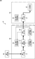
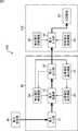
ここで、図3には、図2に示した機能ブロックにおける直流電力システム41を実現するための構造ブロック図が示されている。なお、図3に示す直流電力システム41では、図2に示した構成と共通するブロックに対して同一の符号が付されており、その詳細な説明は省略する。
図3に示すように、直流電力供給機器42は、CPU(Central Processing Unit)やメモリなどを備えて構成される制御部71を有している。そして、制御部71において、CPUがメモリに記憶されているプログラムを実行することにより、導出電圧検索機能54、必要電圧導出機能55、および必要電圧指定機能56の各機能が実現される。
また、電力入力部61は、直流機器43の外部に追加される電力入力装置45に内蔵することができ、電力入力部61は、導出電圧切断機能63を実現する電力制限回路72を備えて構成される。このように、直流機器43は、電力入力装置45に接続され、電力入力装置45を介して直流電力供給機器42から直流電力が供給される。
このように、直流電力システム41では、電力制限回路72を追加する簡易な構成と、制御部71で実行される単純なアルゴリズムで、直流機器43の必要電圧を認識して、必要電圧の直流電力を直流機器43に供給することができる。
次に、図4は、本技術を適用した直流電力システムの第2の実施の形態の構成例を示す機能ブロック図である。
図4に示す直流電力システム41Aにおいて、図2の直流電力システム41と共通するブロックについては同一の符号を付し、その詳細な説明を省略する。即ち、直流電力システム41Aは、直流電力供給機器42および直流機器43Aから構成される。そして、直流電力供給機器42は、図2の直流電力供給機器42と同様に、電力入力部51、電力変換部52、電力出力部53、導出電圧検索機能54、必要電圧導出機能55、および必要電圧指定機能56を備えて構成される。
また、直流機器43Aは、図2の直流機器43と同様に、電力入力部61、主回路部62、および導出電圧切断機能63を備えて構成される。但し、直流機器43Aは、許容電圧透過機能64を備える点で、図2の直流機器43と異なる構成とされる。
許容電圧透過機能64は、電力入力部61に入力される直流電力の電圧が、主回路部62が動作するために許容される許容電圧であるときのみ、電力入力部61を透過させて直流電力を主回路部62に供給させる機能を有する。ここで、許容電圧とは、直流機器43の必要電圧を含み、直流機器43が最低限許容できる範囲の電圧であり、図7を参照して後述するように、直流機器43の必要電圧を中心とした所定範囲の電圧である。例えば、許容電圧は、直流機器43の仕様上は決定されていないが、設計誤差として許容できる範囲を指定し、許容電圧として0Vとしてもよいが、その場合には、直流電力供給機器42(もしくは、電力変換部52、電力出力部53、導出電圧検索機能54)の精度が高いものが必要となる。
ここで、図5には、図4に示した機能ブロックにおける直流電力システム41Aを実現するための構造ブロック図が示されている。なお、図5に示す直流電力システム41Aでは、図3および図4に示した構成と共通するブロックに対して同一の符号が付されており、その詳細な説明は省略する。
図5に示すように、直流電力供給機器42は、制御部71において、導出電圧検索機能54、必要電圧導出機能55、および必要電圧指定機能56の各機能が実現される。また、電力入力部61Aは、直流機器43の外部に追加される電力入力装置45Aに内蔵することができ、電力入力部61Aは、導出電圧切断機能63を実現する電力制限回路72と、許容電圧透過機能64を実現する電力制限回路73とを備えて構成される。このように、直流機器43は、電力入力装置45に接続され、電力入力装置45を介して直流電力供給機器42から直流電力が供給される。
このように、直流電力システム41Aでは、電力制限回路72および電力制限回路73を追加する簡易な構成と、制御部71で実行される単純なアルゴリズムで、直流機器43の必要電圧を認識して、必要電圧の直流電力を直流機器43に供給することができる。
なお、電力入力部61Aが直流機器43に内蔵される構成としてもよい。即ち、図6に示す直流電力システム41Aの変形例のように、直流電力システム41A’の直流機器43’が、電力入力部61Aおよび主回路部62を備えて構成することができる。
また、直流機器43の許容電圧が厳密に設定されている場合には、できるだけ確実に必要電圧を導出する必要があり、このような場合には、電力制限回路72に替えて、ソフトウエア的に導出電圧切断機能63を実現することで、正確な導出電圧での切断を、長期間に亘って期待することができる。
次に、図7を参照して、電力入力部61Aの動作について説明する。
図7に示すように、電力入力部61Aにおいて、電力制限回路72を実現する電力制限回路73は、直流電力供給機器42および主回路部62に直列に接続され、電力制限回路73を実現する電力制限回路72の一端は、直流電力供給機器42と電力制限回路73との間の配線に接続され、直流電力供給機器42の他端は、接地されている。
電力制限回路72は、導出電圧切断機能63を実現し、図7の例では、導出電圧Vxとして2.0Vが設定されている。即ち、電力制限回路72は、0Vから2.0Vまでの電圧の直流電力を透過させし、電力入力部61に入力される電圧が2.0Vを超過したときには、直流電力の透過を切断する。
電力制限回路73は、許容電圧透過機能64を実現し、図7の例では、直流機器43の必要電圧が10.0Vとされ、直流機器43Aが動作するために許容される電圧とされる9.5Vから10.5Vまでの電圧の直流電力を透過させ、この範囲以外の電圧の透過を制限する。
このとき、直流電力供給機器42の必要電圧導出機能55には、導出関数f(Vx)としてf(Vx)=Vx×5が設定されており、電力制限回路72により直流電力の電圧が導出電圧Vxである2.0Vを超過したことにより切断されたとき、導出関数f(Vx)に従って必要電圧が10.0Vであると導出する。これにより、直流電力供給機器42から10.0Vの直流電力が出力されると、電力制限回路73を透過して主回路部62に直流電力が供給される。
なお、このとき、不具合が発生して、必要電圧から大きく異なった電圧の直流電力が直流電力供給機器42から出力されたとしても、直流電力が主回路部62に供給されることが電力制限回路73により防止される。このように、電力入力部61Aが電力制限回路73を備えることにより、必要電圧から大きく異なった電圧の直流電力が主回路部62に供給されることを回避して、そのような電圧の直流電力が主回路部62に供給されることによる誤作動や故障の発生を回避することができる。
次に、図8のフローチャートを参照し、直流電力供給機器42が直流機器43の必要電圧を求めて供給する処理について説明する。
ここでは、導出電圧検索機能54は、電力変換部52が出力する電圧を一定段階で徐々に増加させることにより導出電圧Vxを検索する方式(以下、一定段階方式と称する)を用いる例について説明する。また、直流機器43の必要電圧は10.0Vとし、導出電圧切断機能63が電力の入力を切断する導出電圧Vxは2.0Vとし、必要電圧導出機能55には導出関数f(Vx)としてf(Vx)=Vx×5が設定されている。なお、直流機器43の必要電圧の範囲は5.0Vから24.0Vの範囲内とされ、この範囲内の電圧で直流機器43が動作するようにしてもよい。
例えば、直流機器43の接続が検出されると、ステップS11において、導出電圧検索機能54は、電力変換部52に対して初期電圧として、例えば1.0Vの電圧の直流電力を出力するように指定する。
ステップS12において、導出電圧検索機能54は、直流機器43に入力される直流電力が切断されたか否かを判定する。例えば、導出電圧検索機能54は、直流機器43に出力する電流が停止したことが電力出力部53から通知されると、直流機器43に入力される電力が切断されたと判定し、その通知がない場合には、直流機器43に入力される電力は切断されていないと判定する。
ステップS12において、導出電圧検索機能54が、直流機器43に入力される電力が切断されていないと判定した場合、処理はステップS13に進む。ステップS13において、導出電圧検索機能54は、電力変換部52に対して出力する直流電力の電圧を0.2V上昇させるように指定し、処理はステップS12に戻り、以下、同様の処理が繰り返される。
このように、電力変換部52が出力する直流電力の電圧を0.2Vずつ上昇させ、電力出力部53が出力する直流電力の電圧が2.0Vを超過して2.2Vとなると、直流機器43では、導出電圧切断機能63が電力入力部61に対して直流電力の入力を切断させる。つまり、導出電圧切断機能63を実現する電力制限回路72によって直流電力の入力が切断される。そして、電力出力部53が、直流機器43に出力する電流が停止したことを検出して導出電圧検索機能54に通知すると、ステップS12において、導出電圧検索機能54は、直流機器43に入力される直流電力が切断されたと判定し、処理はステップS14に進む。
ステップS14において、導出電圧検索機能54は、電力供給が切断される直前の電圧、即ち、2.0Vを導出電圧Vxとして特定し、必要電圧導出機能55に通知する。
ステップS15において、必要電圧導出機能55は、ステップS14で必要電圧導出機能55から通知された導出電圧Vx(=2.0V)を導出関数f(Vx)=Vx×5に代入し、必要電圧として10.0Vを導出し、必要電圧指定機能56に通知する。
ステップS16において、必要電圧指定機能56は、ステップS15で必要電圧導出機能55から通知された必要電圧(=10.0V)を電力変換部52に対して指定し、処理は終了される。
これにより、電力変換部52は、10.0Vの電圧の直流電力を出力し、直流機器43では、許容電圧透過機能64により10.0Vの電圧の直流電圧が電力入力部61を透過され、必要電圧の直流電流が主回路部62に供給されて、主回路部62が正常に動作することができる。
なお、導出電圧検索機能54は、上述したような一定段階方式を用いて導出電圧Vxを検索する他、二分検索方式を用いて導出電圧Vxを検索してもよい。二分検索方式では、導出電圧Vxが含まれる電圧範囲を二分割する電圧を電力変換部52から順次出力させ、導出電圧Vxが含まれる電圧範囲を狭めることにより導出電圧Vxが検索される。
例えば、二分検索方式では、導出電圧検索機能54は、まず、必要電圧の範囲である5Vから24Vの中間となる14.5Vを導出するための導出電圧(2.9V)で直流電力を出力するように電力変換部52に対して指定する。以降、導出電圧検索機能54は、二分検索方式に従って、出力する電圧を定めて電力変換部52に対して指定し、直流機器43において直流電力の入力が切断されない上限の電圧を導出電圧Vxとして決定することができる。このように、二分検索方式を用いることにより、導出電圧Vxを特定するまでに電力変換部52に電圧を変更させて出力させる回数の低減を図ることができ、より高速に導出電圧Vxを特定することができる。
さらに、導出電圧検索機能54は、一定段階方式および二分検索方式以外にも、様々な検索アルゴリズムを採用することができる。そして、複数の検索アルゴリズムを併用したり、同一の検索アルゴリズムを複数回実行することにより、導出電圧Vxを特定する精度を向上させることができる。
また、導出電圧検索機能54は、過去に直流電力を供給したことのある直流機器43の必要電圧を保持しておき、それらの必要電圧から、直流電力を供給する対象として現在接続されている直流機器43に対する導出電圧の検索を開始する際の所定の電圧を特定する学習機能を備えていてもよい。そして、導出電圧検索機能54は、学習により特定される所定の電圧から直流機器43の導出電圧の検索を開始することができる。例えば、導出電圧検索機能54は、前回までに接続されたことのある直流機器43の必要電圧を保持しておき、それらの必要電圧の平均値を所定の電圧として検索アルゴリズムをスタートさせてもよい。または、導出電圧検索機能54は、直近で接続された所定数の直流機器43のうちの、接続回数が最多である直流機器43の必要電圧を所定の電圧として第1目標に設定して検索アルゴリズムをスタートさせてもよい。
ところで、直流電力システム41を導入した施設では、例えば、直流電力供給機器42は施設の壁内に埋め込まれるように設置されることが想定される。この場合、直流機器43に直流電力を供給するためのケーブルの端子が、壁面に配置される電力出力部53のコネクタに差し込まれるようにして使用される。
例えば、図9のAに示すように、一般的な家庭用のコンセントのように、壁面に設置されるパネル81に電力出力部53が設けられる。図9では、2つの電力出力部53-1および53-2が設けられる例が示されている。
また、図9のBに示すように、壁面に設置されるパネル81Aに、電力出力部53-1から出力される必要電圧を表示する表示部82-1、および、電力出力部53-2から出力される必要電圧を表示する表示部82-2を設けてもよい。表示部82-1および82-2としては、表示内容を保持する際に電力を消費する必要がないデバイスが使用され、例えば、電子ペーパーや表示内容保持液晶などを使用することが好ましい。
このように表示部82-1および82-2を設けることにより、電力出力部53-1および53-2から出力される必要電圧をユーザに認識させることができる。
なお、表示部82-1および82-2と同様に、直流機器43の筐体に配置される電力入力部61のコネクタの近傍に、直流機器43の必要電圧または導出電圧を表示する表示部を設けてもよい。これにより、直流機器43の必要電圧または導出電圧をユーザに認識させることができる。
また、例えば、直流電力供給機器42の電力出力部53は、直流機器43の接続を検出する接続検出手段を備えることができる。
例えば、図10に示すように、電力出力部53は、コネクタ93、スイッチ94、および連動機構95を有して構成される。
コネクタ93は、直流機器43に直流電力を供給するためのケーブル91の端子92が挿入可能な凹型の接続部である。スイッチ94は、直流機器43の接続を検知し、直流機器43が接続されたときにオンとなる。そして、スイッチ94がオフの状態であるときには電力変換部52による直流電力の出力が停止され、スイッチ94がオフからオンの状態に遷移したときに、直流電力供給機器42が直流機器43の必要電圧を求めて供給する処理(図8)が開始される。連動機構95は、ケーブル91の端子92がコネクタ93に挿入されるのに連動して、スイッチ94をオンにする機構である。
このように構成される電力出力部53では、図10のAに示すように、ケーブル91の端子92がコネクタ93から外された状態では、連動機構95はコネクタ93の内側に収納されてスイッチ94はオフとなる。これにより、電力出力部53は、直流機器43が接続されていないと判定して、電力変換部52による直流電力の出力が停止される。
一方、図10のBに示すように、ケーブル91の端子92がコネクタ93に挿入された状態では、連動機構95はコネクタ93の外側に押し出されてスイッチ94はオンとなる。これにより、電力出力部53は、直流機器43が接続されていると判定して、直流電力供給機器42が直流機器43の必要電圧を求めて供給する処理が行われ、電力変換部52から直流電力が出力される。
このように、電力出力部53が、直流機器43の接続を検出する接続検出手段を備えることにより、直流機器43が接続されたときだけに確実に、直流機器43に必要電圧の直流電力を供給することができる。
ここで、本実施の形態では、導出関数f(Vx)として一次関数を用いたが、導出関数f(Vx)は関数として定義できれば、一次関数以外のものを用いてもよい。但し、規定で導出関数f(Vx)を決めた後は、原則的に変更することは禁止される。また、導出関数f(Vx)は、高電圧域では、1Vごとのピッチは広くするのに対し、低電圧域では、1Vごとのピッチを狭くすることができる。これにより、低電圧域では、3.3Vや7.2Vなどが必要電圧となるのに対し、高電圧域では、16Vや19Vなど1Vピッチになるような製品が多数を占める場合において有効となる。また、電気特性(技術的制約)によって導出関数f(Vx)を決定してもよい。なお、導出関数f(Vx)に一次関数を用いて単純変換する場合は、電圧降下の影響を排除することができる。
なお、上述のフローチャートを参照して説明した各処理は、必ずしもフローチャートとして記載された順序に沿って時系列に処理する必要はなく、並列的あるいは個別に実行される処理(例えば、並列処理あるいはオブジェクトによる処理)も含むものである。また、プログラムは、1のCPUにより処理されるものであっても良いし、複数のCPUによって分散処理されるものであっても良い。
また、上述した一連の処理(情報処理方法)は、ハードウエアにより実行することもできるし、ソフトウエアにより実行することもできる。一連の処理をソフトウエアにより実行する場合には、そのソフトウエアを構成するプログラムが、専用のハードウエアに組み込まれているコンピュータ、または、各種のプログラムをインストールすることで、各種の機能を実行することが可能な汎用のコンピュータなどに、プログラムが記録されたプログラム記録媒体からインストールされる。
なお、本実施の形態は、上述した実施の形態に限定されるものではなく、本開示の要旨を逸脱しない範囲において種々の変更が可能である。
41 直流電力システム, 42 直流電力供給機器, 43 直流機器, 44 電力供給部, 45 電力入力装置, 51 電力入力部, 52 電力変換部, 53 電力出力部, 54 導出電圧検索機能, 55 必要電圧導出機能, 56 必要電圧指定機能, 61 電力入力部, 62 主回路部, 63 導出電圧切断機能, 64 許容電圧透過機能, 71 制御部, 72 電力制限回路, 73 電力制限回路, 81 パネル, 82 表示部, 91 ケーブル, 92 端子, 93 コネクタ, 94 スイッチ, 95 連動機構
Claims (15)
- 直流電力を必要とする直流機器、および、前記直流機器に直流電力を供給する直流電力供給機器を備える直流電力システムであって、
前記直流電力供給機器は、
出力する電圧を変更して直流電力を出力することができる電力変換部に対し、所定の方式に従って電圧を変更させながら前記直流機器に直流電力を供給するように指示して、前記直流機器の駆動に必要な必要電圧を導出するために定義された導出電圧を検索する導出電圧検索部と、
前記導出電圧検索部により特定された前記導出電圧から前記必要電圧を導出する必要電圧導出部と、
前記電力変換部に対し、前記必要電圧導出部により導出された前記必要電圧の直流電力を前記直流機器に供給するように指示する必要電圧指定部と
を有し、
前記直流機器は、前記直流電力供給機器から供給される直流電力の電圧が、前記導出電圧以下まで許容し、前記導出電圧を超えたときに直流電力の入力を切断する導出電圧切断部を有する
直流電力システム。 - 前記直流機器は、前記必要電圧を範囲に含み、前記直流機器が動作するために許容される範囲の許容電圧であるときのみ、前記直流機器の主回路部への直流電力の透過を許容する許容電圧透過部をさらに有する
請求項1に記載の直流電力システム。 - 前記必要電圧を導出するための導出関数が予め定義されており、
前記必要電圧導出部は、前記導出電圧検索部により特定された前記導出電圧を前記導出関数に代入することにより前記必要電圧を導出する
請求項1に記載の直流電力システム。 - 前記導出電圧検索部は、前記電力変換部が出力する電圧を一定段階で徐々に増加させる一定段階方式に従って前記電力変換部が出力する電圧を変更させて前記導出電圧を検索する
請求項1に記載の直流電力システム。 - 前記導出電圧検索部は、前記導出電圧が含まれる電圧範囲を二分割する電圧を前記電力変換部から順次出力させる二分検索方式に従って前記電力変換部が出力する電圧を変更させて、前記導出電圧が含まれる電圧範囲を狭めることにより前記導出電圧を検索する
請求項1に記載の直流電力システム。 - 前記導出電圧検索部は、過去に直流電力を供給したことのある前記直流機器の前記必要電圧を保持しておき、それらの前記必要電圧から特定される所定の電圧から前記導出電圧の検索を開始する
請求項1に記載の直流電力システム。 - 前記直流電力供給機器は、前記直流機器に供給する前記必要電圧を表示する表示部をさらに有する
請求項1に記載の直流電力システム。 - 前記直流電力供給機器は、外部機器と導通可能な電力出力部をさらに有し、
前記直流機器は、外部機器と導通可能な電力入力部をさらに有する
請求項1に記載の直流電力システム。 - 前記直流電力供給機器の前記電力出力部は、前記直流機器の接続の有無を検知する検知部を有する
請求項8に記載の直流電力システム。 - 前記検知部により前記直流機器が接続されていることが検知されたとき、前記導出電圧検索部を動作させる
請求項9に記載の直流電力システム。 - 前記検知部により前記直流機器が接続されていないことが検知されているとき、前記電力変換部からの直流電力の出力が停止される
請求項9に記載の直流電力システム。 - 直流電力を必要とする直流機器に直流電力を供給する直流電力供給機器であって、
出力する電圧を変更して直流電力を出力することができる電力変換部に対し、所定の方式に従って電圧を変更させながら前記直流機器に直流電力を供給するように指示して、前記直流機器の駆動に必要な必要電圧を導出するために定義された導出電圧を検索する導出電圧検索部と、
前記導出電圧検索部により特定された前記導出電圧から前記必要電圧を導出する必要電圧導出部と、
前記電力変換部に対し、前記必要電圧導出部により導出された前記必要電圧の直流電力を前記直流機器に供給するように指示する必要電圧指定部と
を備え、
前記直流機器では、前記直流電力供給機器から供給される直流電力の電圧が、前記導出電圧以下まで許容され、前記導出電圧を超えたときに直流電力の入力が切断される
直流電力供給機器。 - 直流電力を必要とする直流機器であって、
前記直流機器に直流電力を供給する直流電力供給機器は、出力する電圧を変更して直流電力を出力することができる電力変換部に対し、所定の方式に従って電圧を変更させながら前記直流機器に直流電力を供給するように指示して、前記直流機器の駆動に必要な必要電圧を導出するために定義された導出電圧を検索する導出電圧検索部と、前記導出電圧検索部により特定された前記導出電圧から前記必要電圧を導出する必要電圧導出部と、前記電力変換部に対し、前記必要電圧導出部により導出された前記必要電圧の直流電力を前記直流機器に供給するように指示する必要電圧指定部とを有しており、
前記直流電力供給機器から供給される直流電力の電圧が、前記導出電圧以下まで許容し、前記導出電圧を超えたときに直流電力の入力を切断する導出電圧切断部を備える
直流機器。 - 直流電力を必要とする直流機器、および、前記直流機器に直流電力を供給する直流電力供給機器を備える直流電力システムによる電力供給方法であって、
前記直流電力供給機器において、
出力する電圧を変更して直流電力を出力することができる電力変換部に対し、所定の方式に従って電圧を変更させながら前記直流機器に直流電力を供給するように指示して、前記直流機器の駆動に必要な必要電圧を導出するために定義された導出電圧を検索し、
特定された前記導出電圧から前記必要電圧を導出し、
前記電力変換部に対し、導出された前記必要電圧の直流電力を前記直流機器に供給するように指示する
ステップを含み、
前記直流機器において、前記直流電力供給機器から供給される直流電力の電圧が、前記導出電圧以下まで許容し、前記導出電圧を超えたときに直流電力の入力を切断するステップを含む
電力供給方法。 - 直流電力を必要とする直流機器、および、前記直流機器に直流電力を供給する直流電力供給機器を備える直流電力システムにおける処理をコンピュータに実行させるプログラムであって、
前記直流電力供給機器において、
出力する電圧を変更して直流電力を出力することができる電力変換部に対し、所定の方式に従って電圧を変更させながら前記直流機器に直流電力を供給するように指示して、前記直流機器の駆動に必要な必要電圧を導出するために定義された導出電圧を検索し、
特定された前記導出電圧から前記必要電圧を導出し、
前記電力変換部に対し、導出された前記必要電圧の直流電力を前記直流機器に供給するように指示する
ステップを含み、
前記直流機器において、前記直流電力供給機器から供給される直流電力の電圧が、前記導出電圧以下まで許容し、前記導出電圧を超えたときに直流電力の入力を切断するステップを含む
処理をコンピュータに実行させるプログラム。
Applications Claiming Priority (2)
| Application Number | Priority Date | Filing Date | Title |
|---|---|---|---|
| JP2012273839A JP6127493B2 (ja) | 2012-12-14 | 2012-12-14 | 直流電力システム、直流電力供給機器、直流機器、電力供給方法、およびプログラム |
| JP2012-273839 | 2012-12-14 |
Publications (1)
| Publication Number | Publication Date |
|---|---|
| WO2014091772A1 true WO2014091772A1 (ja) | 2014-06-19 |
Family
ID=50934076
Family Applications (1)
| Application Number | Title | Priority Date | Filing Date |
|---|---|---|---|
| PCT/JP2013/056409 Ceased WO2014091772A1 (ja) | 2012-12-14 | 2013-03-08 | 直流電力システム、直流電力供給機器、直流機器、電力供給方法、およびプログラム |
Country Status (2)
| Country | Link |
|---|---|
| JP (1) | JP6127493B2 (ja) |
| WO (1) | WO2014091772A1 (ja) |
Citations (4)
| Publication number | Priority date | Publication date | Assignee | Title |
|---|---|---|---|---|
| JPH1080059A (ja) * | 1996-09-03 | 1998-03-24 | Hitachi Ltd | 電圧制御方式及びそれを用いた端末装置 |
| JP2003169476A (ja) * | 2001-11-30 | 2003-06-13 | Toshiba Corp | 電源供給アダプタを接続可能な電子機器 |
| JP2005033946A (ja) * | 2003-07-09 | 2005-02-03 | Sony Corp | 電源アダプタ装置 |
| JP2008219981A (ja) * | 2007-02-28 | 2008-09-18 | Sanyo Electric Co Ltd | 電源装置 |
Family Cites Families (3)
| Publication number | Priority date | Publication date | Assignee | Title |
|---|---|---|---|---|
| JP2000134816A (ja) * | 1998-10-27 | 2000-05-12 | Toshiba Corp | 電子機器及びacアダプタ |
| JP2001245476A (ja) * | 2000-02-28 | 2001-09-07 | Sharp Corp | 電源装置 |
| JP2013093922A (ja) * | 2011-10-24 | 2013-05-16 | Mitsubishi Electric Corp | 直流給電システム |
-
2012
- 2012-12-14 JP JP2012273839A patent/JP6127493B2/ja not_active Expired - Fee Related
-
2013
- 2013-03-08 WO PCT/JP2013/056409 patent/WO2014091772A1/ja not_active Ceased
Patent Citations (4)
| Publication number | Priority date | Publication date | Assignee | Title |
|---|---|---|---|---|
| JPH1080059A (ja) * | 1996-09-03 | 1998-03-24 | Hitachi Ltd | 電圧制御方式及びそれを用いた端末装置 |
| JP2003169476A (ja) * | 2001-11-30 | 2003-06-13 | Toshiba Corp | 電源供給アダプタを接続可能な電子機器 |
| JP2005033946A (ja) * | 2003-07-09 | 2005-02-03 | Sony Corp | 電源アダプタ装置 |
| JP2008219981A (ja) * | 2007-02-28 | 2008-09-18 | Sanyo Electric Co Ltd | 電源装置 |
Also Published As
| Publication number | Publication date |
|---|---|
| JP6127493B2 (ja) | 2017-05-17 |
| JP2014121149A (ja) | 2014-06-30 |
Similar Documents
| Publication | Publication Date | Title |
|---|---|---|
| KR102037200B1 (ko) | 전원 어댑터, 단말기 및 충전회로 임피던스 이상 처리방법 | |
| US9774820B2 (en) | Display system, display device, and HDMI dongle | |
| EP3101763A1 (en) | Terminal, power adapter, and method for processing charging exception | |
| US10148203B2 (en) | Motor driving apparatus including DC link voltage detection unit | |
| EP2463778A1 (en) | Computer system | |
| US11973420B2 (en) | Voltage supply device and voltage supply device control method | |
| KR20140099741A (ko) | 충전장치 및 충전방법 | |
| US10038289B2 (en) | Conversion device | |
| CN105302518A (zh) | 一种计算机设备及其控制方法 | |
| CN206348447U (zh) | 一种电源供应器测试装置 | |
| CN111034208A (zh) | 线缆和连接设备 | |
| US9736396B2 (en) | Signal input switching circuit, method of controlling signal input switching circuit, and display device | |
| JPWO2015136672A1 (ja) | モータ制御装置、モータ制御システム、モータ制御方法、及びモータ制御プログラム | |
| JP6127493B2 (ja) | 直流電力システム、直流電力供給機器、直流機器、電力供給方法、およびプログラム | |
| KR20150017256A (ko) | 밸브 베이스 일렉트로닉스 장치의 시험 장치 | |
| WO2011158310A1 (ja) | 通信装置 | |
| JP2018013932A (ja) | 電子機器 | |
| CN102768570A (zh) | 一种电子设备 | |
| KR20160115495A (ko) | Hdmi 및 dvi 신호 입력을 인식하여 디스플레이포트 신호로 변환하는 장치 및 방법 | |
| KR101916021B1 (ko) | 사물 인터넷 네트워크 접속용 보조장치 | |
| JP6555732B2 (ja) | 蓄電池管理装置及び蓄電池管理方法 | |
| JP2011034422A (ja) | 電源制御システムおよび電源制御方法 | |
| JP2015068961A (ja) | 情報処理装置及びそのインタフェース制御方法、並びにコンピュータ・プログラム | |
| JP4884155B2 (ja) | 起動装置 | |
| CN107846526B (zh) | 信息处理设备和信息处理系统 |
Legal Events
| Date | Code | Title | Description |
|---|---|---|---|
| 121 | Ep: the epo has been informed by wipo that ep was designated in this application |
Ref document number: 13861642 Country of ref document: EP Kind code of ref document: A1 |
|
| NENP | Non-entry into the national phase |
Ref country code: DE |
|
| 122 | Ep: pct application non-entry in european phase |
Ref document number: 13861642 Country of ref document: EP Kind code of ref document: A1 |