WO2014087828A1 - 車両用動力伝達装置 - Google Patents
車両用動力伝達装置 Download PDFInfo
- Publication number
- WO2014087828A1 WO2014087828A1 PCT/JP2013/080900 JP2013080900W WO2014087828A1 WO 2014087828 A1 WO2014087828 A1 WO 2014087828A1 JP 2013080900 W JP2013080900 W JP 2013080900W WO 2014087828 A1 WO2014087828 A1 WO 2014087828A1
- Authority
- WO
- WIPO (PCT)
- Prior art keywords
- output shaft
- power transmission
- output
- input
- downstream portion
- Prior art date
- Legal status (The legal status is an assumption and is not a legal conclusion. Google has not performed a legal analysis and makes no representation as to the accuracy of the status listed.)
- Ceased
Links
Images








Classifications
-
- F—MECHANICAL ENGINEERING; LIGHTING; HEATING; WEAPONS; BLASTING
- F16—ENGINEERING ELEMENTS AND UNITS; GENERAL MEASURES FOR PRODUCING AND MAINTAINING EFFECTIVE FUNCTIONING OF MACHINES OR INSTALLATIONS; THERMAL INSULATION IN GENERAL
- F16H—GEARING
- F16H29/00—Gearings for conveying rotary motion with intermittently-driving members, e.g. with freewheel action
- F16H29/02—Gearings for conveying rotary motion with intermittently-driving members, e.g. with freewheel action between one of the shafts and an oscillating or reciprocating intermediate member, not rotating with either of the shafts
- F16H29/04—Gearings for conveying rotary motion with intermittently-driving members, e.g. with freewheel action between one of the shafts and an oscillating or reciprocating intermediate member, not rotating with either of the shafts in which the transmission ratio is changed by adjustment of a crank, an eccentric, a wobble-plate, or a cam, on one of the shafts
-
- B—PERFORMING OPERATIONS; TRANSPORTING
- B60—VEHICLES IN GENERAL
- B60K—ARRANGEMENT OR MOUNTING OF PROPULSION UNITS OR OF TRANSMISSIONS IN VEHICLES; ARRANGEMENT OR MOUNTING OF PLURAL DIVERSE PRIME-MOVERS IN VEHICLES; AUXILIARY DRIVES FOR VEHICLES; INSTRUMENTATION OR DASHBOARDS FOR VEHICLES; ARRANGEMENTS IN CONNECTION WITH COOLING, AIR INTAKE, GAS EXHAUST OR FUEL SUPPLY OF PROPULSION UNITS IN VEHICLES
- B60K1/00—Arrangement or mounting of electrical propulsion units
-
- F—MECHANICAL ENGINEERING; LIGHTING; HEATING; WEAPONS; BLASTING
- F16—ENGINEERING ELEMENTS AND UNITS; GENERAL MEASURES FOR PRODUCING AND MAINTAINING EFFECTIVE FUNCTIONING OF MACHINES OR INSTALLATIONS; THERMAL INSULATION IN GENERAL
- F16H—GEARING
- F16H57/00—General details of gearing
- F16H57/02—Gearboxes; Mounting gearing therein
- F16H57/027—Gearboxes; Mounting gearing therein characterised by means for venting gearboxes, e.g. air breathers
-
- F—MECHANICAL ENGINEERING; LIGHTING; HEATING; WEAPONS; BLASTING
- F16—ENGINEERING ELEMENTS AND UNITS; GENERAL MEASURES FOR PRODUCING AND MAINTAINING EFFECTIVE FUNCTIONING OF MACHINES OR INSTALLATIONS; THERMAL INSULATION IN GENERAL
- F16H—GEARING
- F16H57/00—General details of gearing
- F16H57/04—Features relating to lubrication or cooling or heating
- F16H57/0412—Cooling or heating; Control of temperature
- F16H57/0415—Air cooling or ventilation; Heat exchangers; Thermal insulations
- F16H57/0416—Air cooling or ventilation
-
- B—PERFORMING OPERATIONS; TRANSPORTING
- B60—VEHICLES IN GENERAL
- B60K—ARRANGEMENT OR MOUNTING OF PROPULSION UNITS OR OF TRANSMISSIONS IN VEHICLES; ARRANGEMENT OR MOUNTING OF PLURAL DIVERSE PRIME-MOVERS IN VEHICLES; AUXILIARY DRIVES FOR VEHICLES; INSTRUMENTATION OR DASHBOARDS FOR VEHICLES; ARRANGEMENTS IN CONNECTION WITH COOLING, AIR INTAKE, GAS EXHAUST OR FUEL SUPPLY OF PROPULSION UNITS IN VEHICLES
- B60K1/00—Arrangement or mounting of electrical propulsion units
- B60K2001/001—Arrangement or mounting of electrical propulsion units one motor mounted on a propulsion axle for rotating right and left wheels of this axle
-
- Y—GENERAL TAGGING OF NEW TECHNOLOGICAL DEVELOPMENTS; GENERAL TAGGING OF CROSS-SECTIONAL TECHNOLOGIES SPANNING OVER SEVERAL SECTIONS OF THE IPC; TECHNICAL SUBJECTS COVERED BY FORMER USPC CROSS-REFERENCE ART COLLECTIONS [XRACs] AND DIGESTS
- Y10—TECHNICAL SUBJECTS COVERED BY FORMER USPC
- Y10T—TECHNICAL SUBJECTS COVERED BY FORMER US CLASSIFICATION
- Y10T74/00—Machine element or mechanism
- Y10T74/15—Intermittent grip type mechanical movement
- Y10T74/1503—Rotary to intermittent unidirectional motion
- Y10T74/1508—Rotary crank or eccentric drive
Definitions
- the present invention relates to a power transmission apparatus for a vehicle including a crank type continuously variable transmission mechanism.
- Power transmission apparatus for vehicle provided with a plurality of crank type transmission units that convert rotation of an input shaft connected to an engine into reciprocating motion of a connecting rod and convert reciprocating motion of a connecting rod into rotational motion of an output shaft by a one-way clutch are known from the following patent document 1.
- the output shaft is supported by the transmission case via a bearing, and the ends of the connecting rods of the plurality of transmission units are respectively via one-way clutches. Since it is connected to the output shaft, the output shaft can not be rotated even if any one of these bearings or one-way clutch fails, and the drive wheel connected to the output shaft is locked and the vehicle can not run. It could be
- the present invention has been made in view of the above-described circumstances, and it is an object of the present invention to provide a power transmission apparatus for a vehicle including a crank type transmission unit, which enables minimum travel of the vehicle even if the output shaft is fixed. Do.
- a plurality of transmission units transmitting the rotation of an input shaft connected to a drive source to an output shaft are juxtaposed between the input shaft and the output shaft, and the transmission unit
- the eccentricity from the axis of the input shaft is variable, and the input side fulcrum which rotates with the input shaft, the first one-way clutch connected to the output shaft, and the input member of the first one-way clutch Power transmission for vehicles provided with an output side fulcrum provided in the vehicle, a connecting rod reciprocated by connecting both ends to the input side fulcrum and the output side fulcrum, and a speed change actuator for changing the eccentricity of the input side fulcrum
- the output shaft includes an output shaft main body connected to the transmission unit and an output shaft downstream portion downstream of the output shaft main body in the power transmission direction,
- the output shaft main body and a vehicular power transmitting device according to a first feature in that a clutch between the output shaft downstream portion is proposed.
- a power transmission member is connected to the input rotary member provided on the input shaft and the output rotary member provided on the downstream portion of the output shaft, and the output rotary member Is engaged between the output shaft downstream portion and the output shaft downstream when the number of rotations of the output shaft downstream portion exceeds the number of rotations of the output rotating member, and the number of rotations of the output shaft downstream portion is
- a second feature is that a second one-way clutch that disengages when the rotational speed falls below and a selection switching unit that couples or disengages the output rotary member to the output shaft downstream portion are disposed.
- a power transmission apparatus for a vehicle according to a third feature is that the one-way clutch is disengaged when the rotation speed of the output shaft main body falls below the rotation speed of the output shaft downstream.
- a rotating member disposed between the drive source and the input shaft, a first case covering the rotating member, and a second case covering the clutch
- a suction port formed in the first case so as to face the outer periphery of the rotating member, a communication port for communicating the inside of the first case with the inside of the second case, and the second case formed in the second case
- a power transmission apparatus for a vehicle comprising: an exhaust port.
- the suction port is disposed on the opposite side of the output shaft with respect to the input shaft, and the discharge port is of the input shaft with respect to the output shaft.
- a power transmission apparatus for a vehicle which is characterized in that it is disposed on the opposite side.
- a sixth aspect is characterized in that the suction port is opened toward the front of the vehicle body, and the discharge port is opened toward the rear of the vehicle body.
- a transmission device is proposed.
- a power transmission apparatus for a vehicle according to a seventh feature is that the second case covers the lower side and the front side of the discharge port.
- the power transmission apparatus for a vehicle according to the eighth feature is that the rotating member and the clutch axially overlap. Suggested.
- the first output shaft 12 of the embodiment corresponds to the output shaft of the present invention
- the eccentric disk 18 of the embodiment corresponds to the input-side fulcrum of the present invention
- the pin 19c of the embodiment is an output of the present invention
- the outer member 22 of the embodiment corresponds to the input fulcrum of the present invention
- the first sprocket 26 of the embodiment corresponds to the input rotary member of the present invention.
- the second sprocket 27 of the embodiment Corresponds to the output rotary member of the present invention, the endless chain 28 of the embodiment corresponds to the power transmission member of the present invention, the damper 51 of the embodiment corresponds to the rotary member of the present invention, and the output of the embodiment
- the side dog clutch 55 corresponds to the clutch of the present invention
- the third one-way clutch 55 'of the embodiment corresponds to the clutch or one-way clutch of the present invention
- the output side dry multi-plate clutch 55 "of the embodiment is the present invention.
- the engine E of the embodiment corresponds to the drive source of the present invention
- the second power transmission switching mechanism S2 of the embodiment corresponds to the selection switching mechanism of the present invention.
- the input side fulcrum when the input shaft is rotated by the drive source, the input side fulcrum is eccentrically rotated, and when the connecting rod whose one end is connected to the input side fulcrum reciprocates, it is connected to the other end of the connecting rod
- the output fulcrum on the output side reciprocates, and the output shaft is intermittently rotated via the first one-way clutch, whereby the rotation of the input shaft is shifted at a gear ratio corresponding to the eccentricity of the input fulcrum and transmitted to the output shaft Be done.
- the output shaft includes an output shaft main body connected to the transmission unit and an output shaft downstream portion downstream of the output shaft main body in the power transmission direction, and a clutch is disposed between the output shaft main body and the output shaft downstream portion Therefore, when the output shaft main body is stuck and can not be rotated, the drive wheel is locked by the fixed output shaft main body by releasing the clutch and disconnecting the output shaft downstream from the output shaft main body. It is possible to prevent the vehicle from moving to the repair shop without trouble.
- the input rotary member provided on the input shaft and the output rotary member provided on the downstream side of the output shaft are connected by a power transmission member, and the output rotary member and the downstream portion of the output shaft
- engagement is made when the number of rotations of the output shaft downstream portion exceeds the number of rotations of the output rotary member, and the engagement is released when the number of rotations downstream of the output shaft becomes lower than the number of rotations of the output rotary member
- the output switching member is normally uncoupled from the output shaft downstream portion by the selection switching means
- the driving force of the drive source can be input shaft, input rotation member, power transmission member and output rotation member By transmitting to the downstream part of the output shaft via the drive shaft, the vehicle can be made to retreat to the repair shop by the driving force of the drive source, and when the vehicle is stopped, the output rotation to the output shaft downstream part by the selection switching means By disengaging the members, the second one-way clutch slips, so that the operation can be continued without stopping the drive source.
- the clutch is engaged when the number of rotations of the output shaft main body exceeds the number of rotations downstream of the output shaft, and the number of rotations of the output shaft main portion is downstream of the output shaft Since it is a one-way clutch that disengages when it falls below the rotational speed of the motor, the one-way clutch automatically engages when normal and enables transmission of driving force from the transmission unit to the drive wheels, and At the time of sticking, the one-way clutch can be automatically disengaged to interrupt reverse transmission of the driving force from the drive wheels to the transmission unit.
- the rotary member disposed between the drive source and the input shaft, the first case covering the rotary member, the second case covering the clutch, and the outer periphery of the rotary member Because the suction port formed in the first case, the communication port for communicating the inside of the first case with the inside of the second case, and the discharge port formed in the second case are provided, the rotation of the rotating member The cooling air sucked into the first case from the suction port can be supplied from the communication port into the second case to cool the clutch and then discharged from the discharge port. Further, since the cooling air is generated using the existing rotating member, a special cooling fan or the like is not required, and the number of parts and the cost are reduced.
- the suction port is disposed on the opposite side of the output shaft with respect to the input shaft, and the discharge port is disposed on the opposite side of the input shaft with respect to the output shaft.
- the rotary member, the clutch, and the discharge port can be arranged in series to reduce the pressure loss of the cooling air and efficiently cause the cooling air generated by the rotary member to act on the clutch.
- the suction port is opened toward the front of the vehicle body and the discharge port is opened toward the rear of the vehicle body. Therefore, the cooling air generated by the rotating member is assisted by the traveling wind of the vehicle. Thus, the cooling effect of the clutch can be further enhanced.
- the second case covers the lower side and the front side of the discharge port, so that water and mud splashed up by the wheels can be prevented from entering the second case from the discharge port. Can.
- the rotating member and the clutch axially overlap, the cooling air generated by the rotating member can be efficiently supplied to the clutch with a minimum pressure loss.
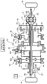
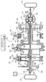
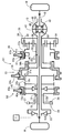
- FIG. 1 is a skeleton diagram of a power transmission system for a vehicle.
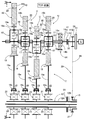
- First Embodiment FIG. 2 is a detailed view of part 2 of FIG.
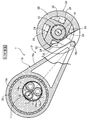
- First Embodiment FIG. 3 is a cross-sectional view taken along line 3-3 of FIG. 2 (TOP state).
- First Embodiment FIG. 4 is a cross-sectional view taken along line 3-3 of FIG. 2 (LOW state).
- First Embodiment FIG. 5 is an explanatory view of the operation in the TOP state.
- First Embodiment FIG. 6 is an operation explanatory view in the LOW state.
- First Embodiment FIG. 7 is a detailed view of part 7 of FIG.
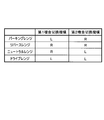
- First Embodiment FIG. 8 is an engagement table of the first and second meshing switching mechanisms.
- FIG. 9 is a torque flow diagram in the parking range.
- FIG. 10 is a torque flow diagram in the reverse range.
- First Embodiment FIG. 11 is a torque flow diagram in the neutral range.
- First Embodiment FIG. 12 is a torque flow diagram (normal traveling state) in the drive range.
- First Embodiment FIG. 13 is a torque flow diagram (engine brake state) in the drive range.
- First Embodiment FIG. 14 is a torque flow diagram (idling stop state) in the drive range.
- First Embodiment FIG. 15 is a torque flow diagram (fail state) in the drive range.
- First Embodiment FIG. 16 is a detailed view of part 16 of FIG.
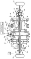
- First Embodiment FIG. 17 is a diagram corresponding to FIG.
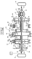
- Second Embodiment FIG. 18 is a diagram corresponding to FIG.
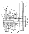
- Third Embodiment FIG. 19 is an enlarged view of part 19 of FIG.
- Third Embodiment FIG. 20 is a sectional view
- FIGS. 1 to 16 a first embodiment of the present invention will be described based on FIGS. 1 to 16.
- the power transmission apparatus for a vehicle for transmitting the driving force of the engine E to the drive wheels W, W via the left and right axles 10, 10 comprises a continuously variable transmission T and a first power transmission switching mechanism. It comprises S1, a second power transmission switching mechanism S2, and a differential gear D.
- the first power transmission switching mechanism S1 can switch between a parking range, a reverse range, a neutral range, and a drive range.
- the second power transmission switching mechanism S2 is capable of switching between normal travel and engine braking, idling stop and fail.
- the input shaft 11 is composed of an input shaft main body 11A and an input shaft upstream portion 11B on the upstream side (engine E side) in the driving force transmission direction than the input shaft main body 11A.
- the portion 11A is connected to the continuously variable transmission T, and the input shaft upstream portion 11B is connected to the engine E.
- a damper 51 is provided between the input shaft upstream portion 11B and the engine E, and an input-side dog clutch 52 is provided between the input shaft main portion 11A and the input shaft upstream portion 11B.
- the input dog clutch 52 is normally maintained in the engaged state, but is disengaged when the input shaft main portion 11A described later is fixed, and the input shaft main portion 11A and the input shaft upstream portion 11B are separated.
- the output shaft 12 is composed of an output shaft body 12A and an output shaft downstream portion 12B on the downstream side (drive wheels W and W side) of the output shaft body 12A in the driving force transmission direction, and the output shaft body 12A is The output shaft downstream portion 12B is connected to the continuously variable transmission T, and is connected to the second power transmission switching mechanism S2.
- An output dog clutch 55 is provided between the output shaft main body 12A and the output shaft downstream portion 12B. The output dog clutch 55 is normally maintained in the engaged state, but is disengaged when the output shaft main portion 12A described later is fixed, and the output shaft main portion 12A and the output shaft downstream portion 12B are separated.
- the right end of the input shaft main portion 11A is supported by a transmission case (not shown) via a ball bearing 53, and the left end of the input shaft main portion 11A is the left end of the input shaft upstream portion 11B.
- the outer periphery fits in a relatively rotatable manner.
- the inner periphery of the input dog clutch 52 is spline-fitted to the outer periphery of the input shaft main body 11A and the outer periphery of the input shaft upstream portion 11B, and the input dog clutch 52 is moved leftward with the fork 54.
- the input shaft main body portion 11A and the input shaft upstream portion 11B are separated by the splines of the above being separated from the splines of the input shaft upstream portion 11B.
- the structure of the output dog clutch 55 is substantially the same as the structure of the input dog clutch 52 described above.
- the continuously variable transmission T is formed by axially superposing a plurality of (four in the embodiment) transmission units U having the same structure.
- These transmission units U have a common input shaft 11 and a common first output shaft 12 arranged in parallel, and the rotation of the input shaft 11 is decelerated or accelerated and transmitted to the first output shaft 12 Ru.
- the rotor 14b of the transmission actuator 14 is fixed to the rotary shaft 14a, and the stator 14c is fixed to the casing.
- the rotation shaft 14 a of the transmission actuator 14 can rotate at the same speed as the input shaft 11 and can rotate relative to the input shaft 11 at different speeds.
- a first pinion 15 is fixed to the input shaft 11 penetrating the rotation shaft 14 a of the transmission actuator 14, and a crank-like carrier 16 is connected to the rotation shaft 14 a of the transmission actuator 14 so as to straddle the first pinion 15.
- Two second pinions 17, 17 having the same diameter as the first pinion 15 are supported via pinion pins 16a, 16a at positions forming an equilateral triangle in cooperation with the first pinion 15, respectively.
- a ring gear 18 a eccentrically formed inside the disc-shaped eccentric disc 18 meshes with the first pinion 15 and the second pinions 17 and 17.
- a ring portion 19 b provided at one end of a rod portion 19 a of the connecting rod 19 is fitted on the outer peripheral surface of the eccentric disk 18 relatively rotatably via a ball bearing 20.
- the first one-way clutch 21 provided on the outer periphery of the first output shaft 12 is disposed inside the outer member 22 and the ring-shaped outer member 22 pivotally supported by the rod portion 19a of the connecting rod 19 via the pin 19c.
- the spring 24 is disposed in a bowl-like space formed between the inner member 23 fixed to the first output shaft 12 and the arc surface of the inner periphery of the outer member 22 and the plane of the outer periphery of the inner member 23. And rollers 25...
- the gear shift unit U differs by 90 °.
- the eccentric disc 18 of the transmission unit U at the left end is displaced upward with respect to the input shaft 11, and the eccentric disc 18 of the third transmission unit U from the left with respect to the input shaft 11.
- the eccentric disks 18, 18 of the second and fourth transmission units U, U from the left, which are displaced downward, are located at the middle in the vertical direction.
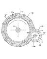
- the continuously variable transmission T includes an auxiliary power transmission path capable of transmitting the driving force in a path different from the six transmission units U. That is, the outer circumferences of the first sprocket 26 provided on the input shaft upstream portion 11B on the upstream side (engine E side) of the input shaft 12 and the output shaft downstream portion 12B on the downstream side (differential gear D side) of the first output shaft 13 Are connected by an endless chain 28 to a second sprocket 27 provided on a transmission shaft 13 which is relatively rotatably fitted to the first sprocket 26, the second sprocket 27 and the endless chain 28 are auxiliary power transmission means 29.
- the first power transmission switching mechanism S1 is rotatable relative to the outer periphery of the axle 10 in addition to the cylindrical first output shaft 12 fitted relative to the outer periphery of the axle 10 in a relatively rotatable manner. It has a cylindrical second output shaft 31 to be fitted, and a cylindrical third output shaft 32 fitted to the outer periphery of the second output shaft 31 so as to be capable of relative rotation.
- a fourth outer peripheral spline 12a is formed at the right end of the output shaft downstream portion 12B of the first output shaft 12
- a fifth outer peripheral spline 31a is formed at the left end of the second output shaft 31, and a sixth at the left end of the third output shaft 32
- An outer peripheral spline 32a is formed.
- the fourth outer peripheral spline 12a, the fifth outer peripheral spline 31a and the sixth outer peripheral spline 32a constituting the first meshing switching mechanism 33 consisting of dog clutches are axially aligned, and the fifth outer peripheral spline 31a and the sixth outer peripheral spline 32a
- the outer diameters are equal to each other and smaller than the outer diameter of the fourth outer peripheral spline 12a.
- the sleeve 34 of the first meshing switching mechanism 33 includes a second inner peripheral spline 34a having a large outer diameter and a third inner peripheral spline 34b having a small outer diameter.
- the second inner peripheral spline 34a has a fourth outer periphery.
- the third inner peripheral splines 34b are always in mesh with the sixth outer peripheral splines 32a, and the third inner peripheral splines 34b are in mesh with the fifth outer peripheral splines 31a only when moving left as shown in FIG. That is, when the sleeve 34 is moved rightward from the left moving state shown in FIG. 7 by the fork 34c, the meshing between the third inner peripheral spline 34b and the fifth outer peripheral spline 31a is released.
- the planetary gear mechanism 35 includes a sun gear 36 as a first element, a carrier 37 as a third element, a ring gear 38 as a second element, and a plurality of pinions 39 relatively rotatably supported by the carrier 37.
- the pinions 39 engage with the sun gear 36 and the ring gear 38.
- the sun gear 36 is connected to the right end of the third output shaft 32, and the ring gear 38 is connected to the right end of the second output shaft 31.
- a first inner spline 41a formed on a sleeve 41 of a second meshing switching mechanism 40 formed of a dog clutch is engaged with an outer peripheral spline 37a formed on an outer peripheral portion of the carrier 37 and an outer peripheral spline 42a formed on a casing 42. Therefore, when the sleeve 41 moves leftward with the fork 41b to the position shown in FIG. 7, the carrier 37 is separated from the casing 42, and when the sleeve 41 moves rightward with the fork 41b from the position shown in FIG. Be done.
- the second power transmission switching mechanism S2 is provided between the transmission shaft 13 and the output shaft downstream portion 12B, and includes a first outer peripheral spline 13a provided on the transmission shaft 13 and a second provided on the output shaft downstream portion 12B.
- a second one-way clutch disposed between the outer peripheral spline 12b and the third outer peripheral spline 12c, a sleeve 43 provided with an inner peripheral spline 43a, a fork 43b for driving the sleeve 43, and the output shaft downstream portion 12B and the second outer peripheral spline 12b And 45.
- the sleeve 43 has a left movement position for coupling the first outer peripheral spline 13a and the second outer peripheral spline 12b, a central position for connecting the first outer peripheral spline 13a, the second outer peripheral spline 12b and the third outer peripheral spline 12c, and a second outer periphery. It is possible to take the right moving position where the spline 12b and the third outer peripheral spline 12c are coupled.
- the second one-way clutch 45 disposed between the output shaft downstream portion 12B and the second outer peripheral spline 12b engages when the number of rotations of the output shaft downstream portion 12B exceeds the number of rotations of the transmission shaft 13.
- a differential case 47 constituting an outer shell of the differential gear D is connected to the right end of the second output shaft 31.
- the differential gear D has a pair of pinions 49, 49 rotatably supported by a pinion shaft 48 fixed to the differential case 47, and a side gear 50 fixed to the end of the axle 10, 10 and meshed with the pinion 49, 49 And 50.
- FIGS. 3 and 5 show a state where the center O of the carrier 16 is on the opposite side of the first output shaft 12 with respect to the first pinion 15 (i.e., the input shaft 11).
- the ratio of the continuously variable transmission T is in the TOP state when the amount of eccentricity of 18 is maximized.
- FIGS. 4 and 6 show a state in which the center O of the carrier 16 is on the same side as the first output shaft 12 with respect to the first pinion 15 (i.e., the input shaft 11).
- the ratio of the continuously variable transmission T becomes LOW when the amount of eccentricity of 18 is minimized.
- FIG. 5A and FIG. 5C show both ends of the rotation of the outer member 22 in the direction of the arrow B.
- the first output shaft 12 rotates counterclockwise (refer to the arrow C) only when the rotation direction of the outer member 22 is counterclockwise (refer to the arrow B).
- the first output shaft 12 is intermittently rotated.
- FIG. 6 shows the operation when operating the continuously variable transmission T in the LOW state.
- the amount of eccentricity of the eccentric disk 18 with respect to the input shaft 11 is zero.
- the input shaft 11 is rotated by the engine E and the rotation shaft 14a of the speed-change actuator 14 is rotated at the same speed as the input shaft 11, the input shaft 11, the rotation shaft 14a, the carrier 16, the first pinion 15,2 With the second pinions 17 and 17 and the eccentric disc 18 integrated, they eccentrically rotate around the input shaft 11 in the counterclockwise direction (see arrow A).
- the amount of eccentricity of the eccentric disk 18 is zero, the stroke of the reciprocating motion of the connecting rod 19 is also zero, and the first output shaft 12 does not rotate.
- the four transmission units U transmit the driving force alternately.
- the first output shaft 12 can be continuously rotated by ensuring that any one of the four first one-way clutches 21 is engaged.
- the sleeve 34 of the first meshing switching mechanism 33 is moved to the left, and the output shaft downstream portion 12B of the first output shaft 12, the second output shaft 31, and the third output shaft 32 are integrated.
- the parking range is established.
- the second output shaft 31 integral with the differential case 47 is coupled to the ring gear 38 of the planetary gear mechanism 35, and the second output shaft 31 is connected via the first meshing switching mechanism 33 and the third output shaft 32. Then, it is connected to the sun gear 36 of the planetary gear mechanism 35, and the carrier 37 of the planetary gear mechanism 35 is further coupled to the casing 42 via the second meshing switching mechanism 40. As a result, the planetary gear mechanism 35 is in a locked state, and the drive wheels W, W connected thereto via the differential gear D are non-rotatably restrained.
- the sleeve 34 of the first meshing switching mechanism 33 is moved to the right to couple the output shaft downstream portion 12B and the third output shaft 32 to separate the second output shaft 31, and
- the sleeve 41 of the meshing switching mechanism 40 is moved to the right to couple the carrier 37 of the planetary gear mechanism 35 to the casing 42, a reverse range is established.
- the driving force output from the continuously variable transmission T to the output shaft downstream portion 12B of the first output shaft 12 is the first meshing switching mechanism 33 ⁇ third output shaft 32 ⁇ sun gear 36 ⁇ carrier 37 ⁇ ring gear 38
- the vehicle can be made to travel backward by being transmitted to the differential case 47 along the path and simultaneously being decelerated by the planetary gear mechanism 35 to be reversely rotated.
- the sleeve 34 of the first meshing switching mechanism 33 is moved to the right to connect the output shaft downstream portion 12B and the third output shaft 32 to separate the second output shaft 31, and
- the sleeve 41 of the meshing switching mechanism 40 is moved leftward to separate the carrier 37 of the planetary gear mechanism 35 from the casing 42, a neutral range is established.
- the sleeve 34 of the first meshing switching mechanism 33 is moved leftward to integrally couple the output shaft downstream portion 12B, the second output shaft 31 and the third output shaft 32, and
- the sleeve 41 of the meshing switching mechanism 40 is moved leftward to separate the carrier 37 of the planetary gear mechanism 35 from the casing 42, a drive range is established.
- the planetary gear mechanism 35 becomes rotatable integrally.
- the driving force output from the continuously variable transmission T to the output shaft downstream portion 12B is in the path of the first meshing switching mechanism 33 ⁇ the second output shaft 31, or the first meshing switching mechanism 33 ⁇ the third output shaft 32.
- the vehicle is transmitted to the differential case 47 through a route of sun gear 36 ⁇ carrier 37 ⁇ ring gear 38 so that the vehicle can travel forward.
- the first output shaft 12 of the continuously variable transmission T can rotate only in the forward traveling direction because the driving force is transmitted through the first one-way clutches 21.
- the first power transmission switching mechanism S1 having the forward / reverse switching function on the downstream side of the first output shaft 12, the vehicle is traveled backward without providing an electric motor for reverse travel and hybridizing be able to.
- the first power transmission switching mechanism S1 can establish the parking range and the neutral range in addition to the drive range and the reverse range, the power transmission itself can be further reduced in size and weight.
- the sleeve 41 of the second power transmission switching mechanism S2. Is moved leftward to connect the first outer peripheral spline 13a of the transmission shaft 13 and the second outer peripheral spline 12b of the output shaft downstream portion 12B. Therefore, during traveling in the drive range or the reverse range, the driving force of the engine E is not only transmitted from the input shaft 11 to the output shaft downstream portion 12B via the transmission unit U ...
- the transmission gear ratio of the transmission unit U is set to be larger than the transmission gear ratio of the auxiliary power transmission means 29, the rotation speed of the transmission shaft 13 (that is, the rotation speed of the second outer peripheral spline 12b) is lower than the output shaft downstream portion 12B.
- the second one-way clutch 45 is disengaged and power transmission via the auxiliary power transmission means 29 is not performed, and the power transmission via the transmission unit U ... causes the vehicle to travel forward or Drive backwards.
- the sleeve 41 of the second power transmission switching mechanism S2 is at the center position, and the first outer peripheral spline 13a of the transmission shaft 13 is made. And the second outer peripheral spline 12b and the third outer peripheral spline 12c of the output shaft downstream portion 12B.
- the transmission shaft 13 and the output shaft downstream portion 12B are directly connected without passing through the second one-way clutch 45, the driving power of the engine E from the input shaft 11 to the auxiliary power transmission means 29, the transmission shaft 13, the output shaft downstream It can be transmitted to the drive wheels W, W through the portion 12B, the first power transmission switching mechanism S1 and the differential gear D, and the vehicle can be traveled forward or backward to the repair shop.
- the auxiliary power transmission means 29 transmits the driving force of the engine E from the upstream portion 11B of the input shaft to the downstream portion 12B of the output shaft without interposing the continuously variable transmission T and retracts the vehicle. It can be run.
- the engine E and the drive wheels W, W are directly connected during this evacuation travel, it is possible to operate the engine brake, but when the vehicle stops, the engine E directly linked to the drive wheels W, W is stalled Have a problem.
- the sleeve 41 of the second power transmission switching mechanism S2 is moved leftward, and the first outer periphery spline 13a of the transmission shaft 13 and the second outer periphery of the output shaft downstream portion 12B
- the driving force of the engine E input to the transmission shaft 13 is not transmitted to the output shaft downstream portion 12B by the second one-way clutch 45 slipping, and the engine E is stalled even when the vehicle is stopped.
- the idling operation can be performed without causing the
- the input dog clutch 52 is disengaged to disconnect the input shaft upstream portion 11B from the input shaft main body 11A.
- To disengage the output shaft downstream portion 12B from the output shaft main body portion 12A, thereby switching to the failure mode described in FIG. 15, and the driving power of the engine E by the auxiliary power transmission means 29 upstream of the input shaft The vehicle can be retreated and traveled without transmitting the driving force to the output shaft main body 12A which is transmitted from the shaft 11B to the output shaft downstream portion 12B without intervention of the continuously variable transmission T.
- the engine E and the drive wheels W, W are directly connected during the escaping travel, so it is possible to operate the engine brake. Further, if the sleeve 41 of the second power transmission switching mechanism S2 is moved leftward while the vehicle is stopped during the escaping travel, the driving force of the engine E input to the transmission shaft 13 causes the second one-way clutch 45 to slip. Since the power is not transmitted to the output shaft downstream portion 12B, the idling operation can be performed without stalling the engine E even when the vehicle is stopped.
- the input dog clutch 52 need not necessarily be disengaged, but the input dog clutch 52 is disengaged to input If the input shaft main portion 11A is separated from the shaft upstream portion 11B, the drag of the continuously variable transmission T can be prevented and the fuel consumption can be reduced.
- forward travel and reverse travel of the vehicle are enabled without requiring an electric motor that increases the axial dimension of the power transmission device for a vehicle, and reverse travel is also possible during forward travel.
- the engine brake can be enabled also during traveling, and moreover, idling stop can be performed while the vehicle is decelerating and traveling can be performed when the transmission unit U has a failure.
- the power transmission device for a vehicle tends to have an axial dimension on the side of the input shaft 11 by providing the transmission shaft 13 on the first output shaft 12 side. It is possible to suppress an increase in size and minimize the axial dimension of the vehicle power transmission as a whole.
- the input-side dog clutch 52 is disposed between the input shaft main body 11A and the input shaft upstream portion 11B
- the output-side dog clutch 55 is disposed between the output shaft main portion 12A and the output shaft downstream portion 12B.
- the vehicle can be retreated and traveled even if the output shaft main body 12A is stuck and broken.
- dog clutches with small axial dimensions for the input side dog clutch 52 and the output side dog clutch 55 it is possible to avoid an increase in the axial dimension of the vehicle power transmission device.
- the damper 51 is disposed between the engine E and the upstream portion 11B of the input shaft, the damping function of the damper 51 can be exhibited during the retreat traveling to secure the ride comfort.
- the output dog clutch 55 disposed between the output shaft main body 12A and the output shaft downstream portion 12B in the first embodiment is replaced with a third one-way clutch 55 '.
- the third one-way clutch 55 ' is engaged when the number of rotations of the output shaft main portion 12A exceeds the number of rotations of the output shaft downstream portion 12B, and the number of rotations of the output shaft main portion 12A is the rotation of the output shaft downstream portion 12B. Disengage when below the number.
- the rotation speed of the fixed output shaft main portion 12A is zero, while the output shaft downstream portion 12B is driven by the auxiliary power transmission means 29.
- the third one-way clutch 55 ' is automatically disengaged to transmit the driving force to the output shaft main body portion 12A, since the third one-way clutch 55' is automatically disengaged in order to rotate at a predetermined rotation speed by the driving force. Can be prevented.
- the driving force is transmitted from the output shaft main body 12A to the output shaft downstream portion 12B, so the third one-way clutch 55 'is automatically engaged and does not disturb the traveling of the vehicle.
- the output-side dog clutch 55 is replaced with the third one-way clutch 55 ', whereby the third one-way clutch is performed without performing any special control when the output shaft body 12A is fixed.
- the clutch 55 ' can be automatically disengaged to allow the vehicle to travel in a retreating manner.
- an output-side dry multi-plate clutch 55 ′ ′ is used instead of the output-side dog clutch 55 of the first embodiment.
- the output-side dry multi-plate clutch 55 ′ ′ is fixed to the output shaft main body 12A.
- the clutch outer 62, the clutch inner 62 fixed to the output shaft downstream portion 12B, the plurality of friction engagement elements 63 arranged between the clutch outer 61 and the clutch inner 62, and the friction engagement elements 63 are closely attached to each other
- a solenoid 64 for engaging the output side dry multi-plate clutch 55 ′ ′.
- a ring gear 51a is provided on the outer periphery of the damper 51 provided at the upstream portion 11B of the input shaft.
- the ring gear 51a is engageable with a pinion of a starter motor (not shown).
- the damper 51 and the output-side dry multi-plate clutch 55 ′ ′ overlap in the axial direction, the damper 51 is accommodated in the first case 65, and the output-side dry multi-plate clutch 55 ′ ′ is continuous with the first case 65 It is stored in the case 66.
- a suction port 67 facing the outer periphery of the ring gear 51a is formed in the first case 65, and a discharge port 68 facing the outer periphery of the output-side dry multi-plate clutch 55 ′ ′ is formed in the second case 66.
- a communication hole 69 is formed between the two cases 66.
- the suction port 67, the damper 51, the communication hole 69, the output-side dry multi-plate clutch 55 ′ ′, and the discharge port 68 are arranged in order from the vehicle body front toward the vehicle body rear. Be done.
- the second case 66 includes a wall 66 a that covers the lower side and the front side of the discharge port 68.
- the suction port 67 is disposed on the opposite side (front side) of the output shaft 12 with respect to the input shaft 11, and the outlet 68 is disposed on the opposite side (rear side) of the input shaft 11 with respect to the output shaft 12.
- the suction port 67, the damper 51, the output-side dry multi-plate clutch 55 ′ ′ and the discharge port 68 are arranged in series, and the cooling air generated by the damper 51 using the traveling wind of the vehicle is output-side dry multi-plate clutch 55 ′ ′ Function efficiently.
- the damper 51 and the output-side dry multi-plate clutch 55 ′ ′ overlap in the axial direction, the cooling air generated by the damper 51 can be efficiently supplied to the output-side dry multi-plate clutch 55 ′ ′ with minimum pressure loss. Can.
- the second case 66 covers the lower part and the front of the discharge port 68 with the wall portion 66 a, it is possible to prevent water and mud splashed by the wheels from entering the second case 66 from the discharge port 68.
- the number of transmission units U is not limited to four in the embodiment.
- the clutch according to the present invention is not limited to the dog clutch 55, the one-way clutch 55 'or the output side dry multi-disc clutch 55 "of the embodiment, and any type of clutch can be adopted.
- the rotating member of the present invention is not limited to the ring gear 51a of the damper 51 of the embodiment, but may be any rotating member such as a gear or a clutch.
Landscapes
- Engineering & Computer Science (AREA)
- General Engineering & Computer Science (AREA)
- Mechanical Engineering (AREA)
- Chemical & Material Sciences (AREA)
- Combustion & Propulsion (AREA)
- Transportation (AREA)
- Transmission Devices (AREA)
- General Details Of Gearings (AREA)
- Arrangement Of Transmissions (AREA)
- Structure Of Transmissions (AREA)
Abstract
Description
12 第1出力軸(出力軸)
12A 出力軸本体部
12B 出力軸下流部
14 変速アクチュエータ
18 偏心ディスク(入力側支点)
19 コネクティングロッド
19c ピン(出力側支点)
21 第1ワンウェイクラッチ
22 アウター部材(入力部材)
26 第1スプロケット(入力回転部材)
27 第2スプロケット(出力回転部材)
28 無端チェーン(動力伝達部材)
45 第2ワンウェイクラッチ
51 ダンパー(回転部材)
55 出力側ドグクラッチ(クラッチ)
55′ 第3ワンウェイクラッチ(クラッチ、ワンウェイクラッチ)
55″ 出力側乾式多板クラッチ(クラッチ)
65 第1ケース
66 第2ケース
67 吸入口
68 排出口
69 連通孔
E エンジン(駆動源)
S2 第2動力伝達切換機構(選択切換手段)
U 変速ユニット
Claims (8)
- 駆動源(E)に接続された入力軸(11)の回転を出力軸(12)に伝達する複数の変速ユニット(U)を前記入力軸(11)および前記出力軸(12)間に並置し、
前記変速ユニット(U)の各々は、
前記入力軸(11)の軸線からの偏心量が可変であって該入力軸(11)と共に回転する入力側支点(18)と、
前記出力軸(12)に接続された第1ワンウェイクラッチ(21)と、
前記第1ワンウェイクラッチ(21)の入力部材(22)に設けられた出力側支点(19c)と、
前記入力側支点(18)および前記出力側支点(19c)に両端を接続されて往復運動するコネクティングロッド(19)と、
前記入力側支点(18)の偏心量を変更する変速アクチュエータ(14)とを備える車両用動力伝達装置であって、
前記出力軸(12)は、前記変速ユニット(U)に接続された出力軸本体部(12A)と、前記出力軸本体部(12A)よりも動力伝達方向下流側の出力軸下流部(12B)とからなり、前記出力軸本体部(12A)および前記出力軸下流部(12B)間にクラッチ(55,55′,55″)を配置したことを特徴とする車両用動力伝達装置。 - 前記入力軸(11)に設けた入力回転部材(26)と前記出力軸下流部(12B)に設けた出力回転部材(27)とを動力伝達部材(28)で接続し、前記出力回転部材(27)と前記出力軸下流部(12B)との間に、前記出力軸下流部(12B)の回転数が前記出力回転部材(27)の回転数を上回ったときに係合し、前記出力軸下流部(12B)の回転数が前記出力回転部材(27)の回転数を下回ったときに係合解除する第2ワンウェイクラッチ(45)と、前記出力軸下流部(12B)に対して前記出力回転部材(27)を結合あるいは結合解除する選択切換手段(S2)とを配置したことを特徴とする、請求項1に記載の車両用動力伝達装置。
- 前記クラッチ(55′)は、前記出力軸本体部(12A)の回転数が前記出力軸下流部(12B)の回転数を上回ったときに係合し、前記出力軸本体部(12A)の回転数が前記出力軸下流部(12B)の回転数を下回ったときに係合解除するワンウェイクラッチであることを特徴とする、請求項1または請求項2に記載の車両用動力伝達装置。
- 前記駆動源(E)および前記入力軸(11)間に配置された回転部材(51)と、前記回転部材(51)を覆う第1ケース(65)と、前記クラッチ(55″)を覆う第2ケース(66)と、前記回転部材(51)の外周に対向するように前記第1ケース(65)に形成された吸入口(67)と、前記第1ケース(65)の内部を前記第2ケース(66)の内部に連通させる連通口(69)と、前記第2ケース(66)に形成された排出口(68)とを備えることを特徴とする、請求項1に記載の車両用動力伝達装置。
- 前記吸入口(67)は前記入力軸(11)に対して前記出力軸(12)の反対側に配置され、前記排出口(68)は前記出力軸(11)に対して前記入力軸(11)の反対側に配置されることを特徴とする、請求項4に記載の車両用動力伝達装置。
- 前記吸入口(67)は車体前方に向けて開口し、前記排出口(68)は車体後方に向けて開口することを特徴とする、請求項5に記載の車両用動力伝達装置。
- 前記第2ケース(66)は前記排出口(68)の下方および前方を覆うことを特徴とする、請求項6に記載の車両用動力伝達装置。
- 前記回転部材(51)および前記クラッチ(55″)は軸方向にオーバラップすることを特徴とする、請求項4~請求項7の何れか1項に記載の車両用動力伝達装置。
Priority Applications (5)
| Application Number | Priority Date | Filing Date | Title |
|---|---|---|---|
| BR112015012217A BR112015012217A2 (pt) | 2012-12-05 | 2013-11-15 | dispositivo de transmissão de energia de veículo |
| DE112013005785.9T DE112013005785T5 (de) | 2012-12-05 | 2013-11-15 | Fahrzeugleistungsübertragungsvorrichtung |
| CN201380060138.4A CN104797857B (zh) | 2012-12-05 | 2013-11-15 | 车辆用动力传递装置 |
| JP2014551020A JP6137702B2 (ja) | 2012-12-05 | 2013-11-15 | 車両用動力伝達装置 |
| US14/442,851 US20150276032A1 (en) | 2012-12-05 | 2013-11-15 | Vehicle power transmission device |
Applications Claiming Priority (2)
| Application Number | Priority Date | Filing Date | Title |
|---|---|---|---|
| JP2012-266638 | 2012-12-05 | ||
| JP2012266638 | 2012-12-05 |
Publications (1)
| Publication Number | Publication Date |
|---|---|
| WO2014087828A1 true WO2014087828A1 (ja) | 2014-06-12 |
Family
ID=50883253
Family Applications (1)
| Application Number | Title | Priority Date | Filing Date |
|---|---|---|---|
| PCT/JP2013/080900 Ceased WO2014087828A1 (ja) | 2012-12-05 | 2013-11-15 | 車両用動力伝達装置 |
Country Status (6)
| Country | Link |
|---|---|
| US (1) | US20150276032A1 (ja) |
| JP (1) | JP6137702B2 (ja) |
| CN (1) | CN104797857B (ja) |
| BR (1) | BR112015012217A2 (ja) |
| DE (1) | DE112013005785T5 (ja) |
| WO (1) | WO2014087828A1 (ja) |
Cited By (1)
| Publication number | Priority date | Publication date | Assignee | Title |
|---|---|---|---|---|
| JP2016002954A (ja) * | 2014-06-19 | 2016-01-12 | 本田技研工業株式会社 | 車両用動力伝達装置 |
Families Citing this family (2)
| Publication number | Priority date | Publication date | Assignee | Title |
|---|---|---|---|---|
| BR112015012263A2 (pt) * | 2012-12-05 | 2017-07-11 | Honda Motor Co Ltd | dispositivo de transmissão de potência do veículo |
| DE102018215918A1 (de) * | 2018-09-19 | 2020-03-19 | ZF Drivetech (Suzhou) Co.Ltd. | Antriebsvorrichtung für eine elektrisch angetriebene Achse eines Kraftfahrzeugs |
Citations (6)
| Publication number | Priority date | Publication date | Assignee | Title |
|---|---|---|---|---|
| US1557432A (en) * | 1921-03-21 | 1925-10-13 | Defordt Jules Frederic | Variable-speed-transmission mechanism |
| US1945702A (en) * | 1930-02-10 | 1934-02-06 | Pitter Trnst | Variable speed transmission |
| JPS6256661A (ja) * | 1985-09-03 | 1987-03-12 | フオ−ド モ−タ− カンパニ− | 車両用動力伝達機構 |
| JP2005502543A (ja) * | 2001-09-26 | 2005-01-27 | ルーク ラメレン ウント クツプルングスバウ ベタイリグングス コマンディートゲゼルシャフト | 駆動装置 |
| JP2012021592A (ja) * | 2010-07-14 | 2012-02-02 | Honda Motor Co Ltd | 車両用動力伝達装置 |
| JP2012506003A (ja) * | 2008-10-16 | 2012-03-08 | シェフラー テクノロジーズ ゲゼルシャフト ミット ベシュレンクテル ハフツング ウント コンパニー コマンディートゲゼルシャフト | 自動車の伝動装置のための駆動軸アッセンブリ |
Family Cites Families (7)
| Publication number | Priority date | Publication date | Assignee | Title |
|---|---|---|---|---|
| US1343254A (en) * | 1920-06-15 | Gearless variable-speed transmission | ||
| JP2011122671A (ja) * | 2009-12-10 | 2011-06-23 | Toyota Motor Corp | 車両用動力伝達装置 |
| JP5586694B2 (ja) * | 2010-06-15 | 2014-09-10 | 本田技研工業株式会社 | 自動車用駆動システムおよび自動車用駆動システムの制御方法 |
| JP5372842B2 (ja) * | 2010-06-15 | 2013-12-18 | 本田技研工業株式会社 | 車両のエンジン始動装置 |
| JP5492990B2 (ja) * | 2010-06-15 | 2014-05-14 | 本田技研工業株式会社 | 自動車用駆動システム |
| JP5142234B2 (ja) * | 2011-01-06 | 2013-02-13 | 本田技研工業株式会社 | 無段変速機構及び自動車用駆動システム |
| JP5216116B2 (ja) * | 2011-03-25 | 2013-06-19 | 本田技研工業株式会社 | 動力伝達装置およびその制御方法 |
-
2013
- 2013-11-15 JP JP2014551020A patent/JP6137702B2/ja not_active Expired - Fee Related
- 2013-11-15 CN CN201380060138.4A patent/CN104797857B/zh not_active Expired - Fee Related
- 2013-11-15 BR BR112015012217A patent/BR112015012217A2/pt not_active IP Right Cessation
- 2013-11-15 US US14/442,851 patent/US20150276032A1/en not_active Abandoned
- 2013-11-15 DE DE112013005785.9T patent/DE112013005785T5/de not_active Withdrawn
- 2013-11-15 WO PCT/JP2013/080900 patent/WO2014087828A1/ja not_active Ceased
Patent Citations (6)
| Publication number | Priority date | Publication date | Assignee | Title |
|---|---|---|---|---|
| US1557432A (en) * | 1921-03-21 | 1925-10-13 | Defordt Jules Frederic | Variable-speed-transmission mechanism |
| US1945702A (en) * | 1930-02-10 | 1934-02-06 | Pitter Trnst | Variable speed transmission |
| JPS6256661A (ja) * | 1985-09-03 | 1987-03-12 | フオ−ド モ−タ− カンパニ− | 車両用動力伝達機構 |
| JP2005502543A (ja) * | 2001-09-26 | 2005-01-27 | ルーク ラメレン ウント クツプルングスバウ ベタイリグングス コマンディートゲゼルシャフト | 駆動装置 |
| JP2012506003A (ja) * | 2008-10-16 | 2012-03-08 | シェフラー テクノロジーズ ゲゼルシャフト ミット ベシュレンクテル ハフツング ウント コンパニー コマンディートゲゼルシャフト | 自動車の伝動装置のための駆動軸アッセンブリ |
| JP2012021592A (ja) * | 2010-07-14 | 2012-02-02 | Honda Motor Co Ltd | 車両用動力伝達装置 |
Cited By (1)
| Publication number | Priority date | Publication date | Assignee | Title |
|---|---|---|---|---|
| JP2016002954A (ja) * | 2014-06-19 | 2016-01-12 | 本田技研工業株式会社 | 車両用動力伝達装置 |
Also Published As
| Publication number | Publication date |
|---|---|
| CN104797857B (zh) | 2017-09-01 |
| JP6137702B2 (ja) | 2017-05-31 |
| US20150276032A1 (en) | 2015-10-01 |
| DE112013005785T5 (de) | 2015-08-20 |
| CN104797857A (zh) | 2015-07-22 |
| JPWO2014087828A1 (ja) | 2017-01-05 |
| BR112015012217A2 (pt) | 2017-07-11 |
Similar Documents
| Publication | Publication Date | Title |
|---|---|---|
| WO2014017438A1 (ja) | 車両用動力伝達装置 | |
| CN104999909B (zh) | 车辆用动力传递装置 | |
| JP5955411B2 (ja) | 車両用動力伝達装置 | |
| JP6137702B2 (ja) | 車両用動力伝達装置 | |
| CN105190100B (zh) | 车辆用动力传递装置 | |
| JP6103760B2 (ja) | 車両用動力伝達装置 | |
| JP6065331B2 (ja) | 車両用動力伝達装置 | |
| CN105917139B (zh) | 车辆用动力传递装置 | |
| JP6125668B2 (ja) | 車両用動力伝達装置 | |
| JP6080309B2 (ja) | 車両用動力伝達装置 | |
| JP2016217434A (ja) | 車両用動力伝達装置 | |
| JP6032614B2 (ja) | 車両用変速機 | |
| JP6120471B2 (ja) | 車両用動力伝達装置 | |
| JP6215991B2 (ja) | 車両用動力伝達装置 | |
| JP6164439B2 (ja) | 車両用動力伝達装置 |
Legal Events
| Date | Code | Title | Description |
|---|---|---|---|
| 121 | Ep: the epo has been informed by wipo that ep was designated in this application |
Ref document number: 13859636 Country of ref document: EP Kind code of ref document: A1 |
|
| ENP | Entry into the national phase |
Ref document number: 2014551020 Country of ref document: JP Kind code of ref document: A |
|
| WWE | Wipo information: entry into national phase |
Ref document number: 14442851 Country of ref document: US |
|
| WWE | Wipo information: entry into national phase |
Ref document number: 112013005785 Country of ref document: DE Ref document number: 1120130057859 Country of ref document: DE |
|
| REG | Reference to national code |
Ref country code: BR Ref legal event code: B01A Ref document number: 112015012217 Country of ref document: BR |
|
| 122 | Ep: pct application non-entry in european phase |
Ref document number: 13859636 Country of ref document: EP Kind code of ref document: A1 |
|
| ENP | Entry into the national phase |
Ref document number: 112015012217 Country of ref document: BR Kind code of ref document: A2 Effective date: 20150527 |