WO2014084103A1 - 燃料タンク構造 - Google Patents
燃料タンク構造 Download PDFInfo
- Publication number
- WO2014084103A1 WO2014084103A1 PCT/JP2013/081321 JP2013081321W WO2014084103A1 WO 2014084103 A1 WO2014084103 A1 WO 2014084103A1 JP 2013081321 W JP2013081321 W JP 2013081321W WO 2014084103 A1 WO2014084103 A1 WO 2014084103A1
- Authority
- WO
- WIPO (PCT)
- Prior art keywords
- fuel tank
- tank
- fuel
- communication pipe
- orifice plate
- Prior art date
- Legal status (The legal status is an assumption and is not a legal conclusion. Google has not performed a legal analysis and makes no representation as to the accuracy of the status listed.)
- Ceased
Links
Images








Classifications
-
- F—MECHANICAL ENGINEERING; LIGHTING; HEATING; WEAPONS; BLASTING
- F02—COMBUSTION ENGINES; HOT-GAS OR COMBUSTION-PRODUCT ENGINE PLANTS
- F02M—SUPPLYING COMBUSTION ENGINES IN GENERAL WITH COMBUSTIBLE MIXTURES OR CONSTITUENTS THEREOF
- F02M37/00—Apparatus or systems for feeding liquid fuel from storage containers to carburettors or fuel-injection apparatus; Arrangements for purifying liquid fuel specially adapted for, or arranged on, internal-combustion engines
- F02M37/0076—Details of the fuel feeding system related to the fuel tank
- F02M37/0082—Devices inside the fuel tank other than fuel pumps or filters
-
- B—PERFORMING OPERATIONS; TRANSPORTING
- B60—VEHICLES IN GENERAL
- B60K—ARRANGEMENT OR MOUNTING OF PROPULSION UNITS OR OF TRANSMISSIONS IN VEHICLES; ARRANGEMENT OR MOUNTING OF PLURAL DIVERSE PRIME-MOVERS IN VEHICLES; AUXILIARY DRIVES FOR VEHICLES; INSTRUMENTATION OR DASHBOARDS FOR VEHICLES; ARRANGEMENTS IN CONNECTION WITH COOLING, AIR INTAKE, GAS EXHAUST OR FUEL SUPPLY OF PROPULSION UNITS IN VEHICLES
- B60K15/00—Arrangement in connection with fuel supply of combustion engines or other fuel consuming energy converters, e.g. fuel cells; Mounting or construction of fuel tanks
- B60K15/03—Fuel tanks
-
- B—PERFORMING OPERATIONS; TRANSPORTING
- B60—VEHICLES IN GENERAL
- B60K—ARRANGEMENT OR MOUNTING OF PROPULSION UNITS OR OF TRANSMISSIONS IN VEHICLES; ARRANGEMENT OR MOUNTING OF PLURAL DIVERSE PRIME-MOVERS IN VEHICLES; AUXILIARY DRIVES FOR VEHICLES; INSTRUMENTATION OR DASHBOARDS FOR VEHICLES; ARRANGEMENTS IN CONNECTION WITH COOLING, AIR INTAKE, GAS EXHAUST OR FUEL SUPPLY OF PROPULSION UNITS IN VEHICLES
- B60K15/00—Arrangement in connection with fuel supply of combustion engines or other fuel consuming energy converters, e.g. fuel cells; Mounting or construction of fuel tanks
- B60K15/03—Fuel tanks
- B60K15/035—Fuel tanks characterised by venting means
- B60K15/03504—Fuel tanks characterised by venting means adapted to avoid loss of fuel or fuel vapour, e.g. with vapour recovery systems
-
- B—PERFORMING OPERATIONS; TRANSPORTING
- B60—VEHICLES IN GENERAL
- B60K—ARRANGEMENT OR MOUNTING OF PROPULSION UNITS OR OF TRANSMISSIONS IN VEHICLES; ARRANGEMENT OR MOUNTING OF PLURAL DIVERSE PRIME-MOVERS IN VEHICLES; AUXILIARY DRIVES FOR VEHICLES; INSTRUMENTATION OR DASHBOARDS FOR VEHICLES; ARRANGEMENTS IN CONNECTION WITH COOLING, AIR INTAKE, GAS EXHAUST OR FUEL SUPPLY OF PROPULSION UNITS IN VEHICLES
- B60K15/00—Arrangement in connection with fuel supply of combustion engines or other fuel consuming energy converters, e.g. fuel cells; Mounting or construction of fuel tanks
- B60K15/03—Fuel tanks
- B60K15/035—Fuel tanks characterised by venting means
- B60K15/03519—Valve arrangements in the vent line
-
- F—MECHANICAL ENGINEERING; LIGHTING; HEATING; WEAPONS; BLASTING
- F02—COMBUSTION ENGINES; HOT-GAS OR COMBUSTION-PRODUCT ENGINE PLANTS
- F02M—SUPPLYING COMBUSTION ENGINES IN GENERAL WITH COMBUSTIBLE MIXTURES OR CONSTITUENTS THEREOF
- F02M25/00—Engine-pertinent apparatus for adding non-fuel substances or small quantities of secondary fuel to combustion-air, main fuel or fuel-air mixture
- F02M25/08—Engine-pertinent apparatus for adding non-fuel substances or small quantities of secondary fuel to combustion-air, main fuel or fuel-air mixture adding fuel vapours drawn from engine fuel reservoir
- F02M25/0836—Arrangement of valves controlling the admission of fuel vapour to an engine, e.g. valve being disposed between fuel tank or absorption canister and intake manifold
-
- F—MECHANICAL ENGINEERING; LIGHTING; HEATING; WEAPONS; BLASTING
- F02—COMBUSTION ENGINES; HOT-GAS OR COMBUSTION-PRODUCT ENGINE PLANTS
- F02M—SUPPLYING COMBUSTION ENGINES IN GENERAL WITH COMBUSTIBLE MIXTURES OR CONSTITUENTS THEREOF
- F02M25/00—Engine-pertinent apparatus for adding non-fuel substances or small quantities of secondary fuel to combustion-air, main fuel or fuel-air mixture
- F02M25/08—Engine-pertinent apparatus for adding non-fuel substances or small quantities of secondary fuel to combustion-air, main fuel or fuel-air mixture adding fuel vapours drawn from engine fuel reservoir
- F02M25/089—Layout of the fuel vapour installation
-
- B—PERFORMING OPERATIONS; TRANSPORTING
- B60—VEHICLES IN GENERAL
- B60K—ARRANGEMENT OR MOUNTING OF PROPULSION UNITS OR OF TRANSMISSIONS IN VEHICLES; ARRANGEMENT OR MOUNTING OF PLURAL DIVERSE PRIME-MOVERS IN VEHICLES; AUXILIARY DRIVES FOR VEHICLES; INSTRUMENTATION OR DASHBOARDS FOR VEHICLES; ARRANGEMENTS IN CONNECTION WITH COOLING, AIR INTAKE, GAS EXHAUST OR FUEL SUPPLY OF PROPULSION UNITS IN VEHICLES
- B60K15/00—Arrangement in connection with fuel supply of combustion engines or other fuel consuming energy converters, e.g. fuel cells; Mounting or construction of fuel tanks
- B60K15/03—Fuel tanks
- B60K2015/03256—Fuel tanks characterised by special valves, the mounting thereof
- B60K2015/03289—Float valves; Floats therefor
-
- B—PERFORMING OPERATIONS; TRANSPORTING
- B60—VEHICLES IN GENERAL
- B60K—ARRANGEMENT OR MOUNTING OF PROPULSION UNITS OR OF TRANSMISSIONS IN VEHICLES; ARRANGEMENT OR MOUNTING OF PLURAL DIVERSE PRIME-MOVERS IN VEHICLES; AUXILIARY DRIVES FOR VEHICLES; INSTRUMENTATION OR DASHBOARDS FOR VEHICLES; ARRANGEMENTS IN CONNECTION WITH COOLING, AIR INTAKE, GAS EXHAUST OR FUEL SUPPLY OF PROPULSION UNITS IN VEHICLES
- B60K15/00—Arrangement in connection with fuel supply of combustion engines or other fuel consuming energy converters, e.g. fuel cells; Mounting or construction of fuel tanks
- B60K15/03—Fuel tanks
- B60K2015/03328—Arrangements or special measures related to fuel tanks or fuel handling
- B60K2015/03368—Arrangements or special measures related to fuel tanks or fuel handling for preventing overfilling of tanks
-
- B—PERFORMING OPERATIONS; TRANSPORTING
- B60—VEHICLES IN GENERAL
- B60K—ARRANGEMENT OR MOUNTING OF PROPULSION UNITS OR OF TRANSMISSIONS IN VEHICLES; ARRANGEMENT OR MOUNTING OF PLURAL DIVERSE PRIME-MOVERS IN VEHICLES; AUXILIARY DRIVES FOR VEHICLES; INSTRUMENTATION OR DASHBOARDS FOR VEHICLES; ARRANGEMENTS IN CONNECTION WITH COOLING, AIR INTAKE, GAS EXHAUST OR FUEL SUPPLY OF PROPULSION UNITS IN VEHICLES
- B60K15/00—Arrangement in connection with fuel supply of combustion engines or other fuel consuming energy converters, e.g. fuel cells; Mounting or construction of fuel tanks
- B60K15/03—Fuel tanks
- B60K2015/03328—Arrangements or special measures related to fuel tanks or fuel handling
- B60K2015/03447—Arrangements or special measures related to fuel tanks or fuel handling for improving the sealing
-
- B—PERFORMING OPERATIONS; TRANSPORTING
- B60—VEHICLES IN GENERAL
- B60K—ARRANGEMENT OR MOUNTING OF PROPULSION UNITS OR OF TRANSMISSIONS IN VEHICLES; ARRANGEMENT OR MOUNTING OF PLURAL DIVERSE PRIME-MOVERS IN VEHICLES; AUXILIARY DRIVES FOR VEHICLES; INSTRUMENTATION OR DASHBOARDS FOR VEHICLES; ARRANGEMENTS IN CONNECTION WITH COOLING, AIR INTAKE, GAS EXHAUST OR FUEL SUPPLY OF PROPULSION UNITS IN VEHICLES
- B60K15/00—Arrangement in connection with fuel supply of combustion engines or other fuel consuming energy converters, e.g. fuel cells; Mounting or construction of fuel tanks
- B60K15/03—Fuel tanks
- B60K15/035—Fuel tanks characterised by venting means
- B60K15/03504—Fuel tanks characterised by venting means adapted to avoid loss of fuel or fuel vapour, e.g. with vapour recovery systems
- B60K2015/03514—Fuel tanks characterised by venting means adapted to avoid loss of fuel or fuel vapour, e.g. with vapour recovery systems with vapor recovery means
-
- B—PERFORMING OPERATIONS; TRANSPORTING
- B60—VEHICLES IN GENERAL
- B60K—ARRANGEMENT OR MOUNTING OF PROPULSION UNITS OR OF TRANSMISSIONS IN VEHICLES; ARRANGEMENT OR MOUNTING OF PLURAL DIVERSE PRIME-MOVERS IN VEHICLES; AUXILIARY DRIVES FOR VEHICLES; INSTRUMENTATION OR DASHBOARDS FOR VEHICLES; ARRANGEMENTS IN CONNECTION WITH COOLING, AIR INTAKE, GAS EXHAUST OR FUEL SUPPLY OF PROPULSION UNITS IN VEHICLES
- B60K15/00—Arrangement in connection with fuel supply of combustion engines or other fuel consuming energy converters, e.g. fuel cells; Mounting or construction of fuel tanks
- B60K15/03—Fuel tanks
- B60K15/035—Fuel tanks characterised by venting means
- B60K2015/03561—Venting means working at specific times
- B60K2015/03576—Venting during filling the reservoir
-
- B—PERFORMING OPERATIONS; TRANSPORTING
- B60—VEHICLES IN GENERAL
- B60K—ARRANGEMENT OR MOUNTING OF PROPULSION UNITS OR OF TRANSMISSIONS IN VEHICLES; ARRANGEMENT OR MOUNTING OF PLURAL DIVERSE PRIME-MOVERS IN VEHICLES; AUXILIARY DRIVES FOR VEHICLES; INSTRUMENTATION OR DASHBOARDS FOR VEHICLES; ARRANGEMENTS IN CONNECTION WITH COOLING, AIR INTAKE, GAS EXHAUST OR FUEL SUPPLY OF PROPULSION UNITS IN VEHICLES
- B60K15/00—Arrangement in connection with fuel supply of combustion engines or other fuel consuming energy converters, e.g. fuel cells; Mounting or construction of fuel tanks
- B60K15/03—Fuel tanks
- B60K15/035—Fuel tanks characterised by venting means
- B60K2015/0358—Fuel tanks characterised by venting means the venting is actuated by specific signals or positions of particular parts
- B60K2015/0359—Fuel tanks characterised by venting means the venting is actuated by specific signals or positions of particular parts by filler cap or inlet cover position
-
- B—PERFORMING OPERATIONS; TRANSPORTING
- B60—VEHICLES IN GENERAL
- B60Y—INDEXING SCHEME RELATING TO ASPECTS CROSS-CUTTING VEHICLE TECHNOLOGY
- B60Y2400/00—Special features of vehicle units
- B60Y2400/30—Sensors
- B60Y2400/306—Pressure sensors
Definitions
- the present invention relates to a fuel tank structure.
- a sealing valve is provided between the fuel tank and the canister so that the fuel tank is sealed (so-called sealed tank) except when fuel is supplied to the fuel tank or when the tank internal pressure exceeds a predetermined value.
- sealed tank a sealing valve is provided between the fuel tank and the canister so that the fuel tank is sealed (so-called sealed tank) except when fuel is supplied to the fuel tank or when the tank internal pressure exceeds a predetermined value.
- the shutoff valve between the fuel tank and the canister when the shutoff valve between the fuel tank and the canister is opened in a state where the tank internal pressure is high, the high tank internal pressure is a valve (full tank) that regulates the fuel tank full tank. There is a risk that the full tank regulating valve will be closed. If the full tank control valve is closed, the gas in the fuel tank cannot be moved to the canister side, so that it is not possible to refuel or depressurize.
- the present invention provides a fuel tank structure capable of suppressing the closing of the full tank control valve even when the sealing valve between the fuel tank and the canister is opened with the tank internal pressure being high. It is a problem to obtain.
- a fuel tank capable of containing fuel therein, a canister that adsorbs the evaporated fuel in the fuel tank by an adsorbent and releases the gas after adsorbing the evaporated fuel to the atmosphere, and the fuel tank
- a full tank regulating valve that is closed when the fuel level in the fuel tank reaches a preset full tank liquid level and the float floats on the fuel, and the full tank regulating valve
- a communication pipe that communicates between the fuel tank and the canister; a blocking valve that is provided in the communication pipe and that can be opened and closed by control; and a flow suppression member that is provided in the communication pipe and suppresses the flow of gas in the communication pipe.
- the sealing valve when the sealing valve is opened, the fuel tank and the canister are communicated with each other through the communication pipe, so that the gas containing the evaporated fuel in the fuel tank can be moved to the canister.
- the fuel tank can be sealed when the blocking valve is closed.
- the float floats on the fuel and the full tank control valve closes, so that the gas in the fuel tank is not discharged to the outside.
- the fuel supply fuel can reach the fuel supply gun from the inlet pipe or the like.
- the communication pipe is provided with a flow suppressing member, and the flow of gas in the communication pipe is suppressed.
- suppression does not completely stop the flow of gas, but means that the flow is allowed to flow and the flow rate is reduced as compared with the case where there is no flow suppression member.
- the flow suppressing member has a variable mechanism that can change a flow path cross-sectional area of the communication pipe.
- the flow passage cross-sectional area of the communication piping By changing the cross-sectional area of the communication piping with a variable mechanism, for example, when the tank internal pressure exceeds the closing pressure of the full tank restriction valve, the flow passage cross-sectional area is reduced and the full tank restriction valve is closed. If the valve closing pressure of the full tank regulating valve is not exceeded, the flow passage cross-sectional area can be increased, and smooth gas movement from the fuel tank to the canister can be achieved.
- the flow suppressing member has an orifice member that locally reduces a flow path cross-sectional area of the communication pipe.
- the orifice member locally reduces the cross-sectional area of the communication pipe, the flow of gas in the communication pipe can be suppressed. Further, by providing the orifice member, the flow suppressing member can be realized with a simple structure.
- the orifice member includes a first orifice plate having a first orifice hole in close contact with the inside of the communication pipe and having an inner diameter smaller than the inner diameter of the communication pipe;
- a second orifice plate having one or a plurality of communication portions, and the variable mechanism biases the second orifice plate toward the full tank regulating valve so as to be separated from the first orifice plate,
- An urging member is provided that allows the second orifice plate to move to the first orifice plate side by a tank internal pressure that is greater than or equal to a predetermined value acting on the second orifice plate from the fuel tank.
- the second orifice plate When the tank internal pressure applied to the second orifice plate from the fuel tank is less than a predetermined value, the second orifice plate is urged by the urging member and is separated from the first orifice plate. Since the communication portion of the second orifice plate is not closed and the first orifice hole is not closed, the gas in the fuel tank can move to the canister side.
- the second orifice plate moves toward the first orifice plate against the urging force of the urging member.
- the second orifice plate comes into contact with the first orifice plate, a part of the communication portion and a part of the first orifice hole are closed. The gas is moved from the fuel tank to the canister side through a portion that is not blocked in the communication portion.
- the movement of the second orifice plate can change the cross-sectional area of the communication pipe, and a complicated mechanism is unnecessary, so that the structure is highly reliable.
- the present invention has the above-described configuration, even when the closing valve between the fuel tank and the canister is opened in a state where the tank internal pressure of the fuel tank is high, the closing of the full tank regulating valve can be suppressed.
- FIG. 1 is an enlarged cross-sectional view of a full tank regulating valve and its vicinity of a fuel tank structure according to a first embodiment of the present invention. It is a graph which shows qualitatively the relationship between the tank internal pressure and flow volume in 1st Embodiment of this invention. It is sectional drawing which expands the full tank control valve of the fuel tank structure of 2nd Embodiment of this invention, and its vicinity. It is sectional drawing which expands the full tank control valve of the fuel tank structure of 2nd Embodiment of this invention, and its vicinity. It is sectional drawing which expands and shows the orifice member of 2nd Embodiment of this invention, and its vicinity partially.
- FIG. 1 shows a fuel tank structure 12 according to a first embodiment of the present invention.
- FIG. 2 is a sectional view showing the full tank regulating valve 24 constituting the fuel tank structure 12 and the vicinity thereof.
- the fuel tank structure 12 has a fuel tank 14 that can accommodate fuel therein, and a lower end portion of an inlet pipe 16 is connected to an upper portion of the fuel tank. An opening portion at the upper end of the inlet pipe 16 is an oil supply port 16H.
- a fuel gun can be inserted into the fuel filler port 16H to fuel the fuel tank 14.
- the fuel filler port 16H of the inlet pipe 16 is normally opened and closed by a fuel cap 26. During fueling, the fuel cap 26 is removed by a fueling worker or the like.
- a fuel lid 28 is provided outside the fuel cap 26 on the panel of the vehicle body.
- the fuel lid 28 is opened under a predetermined condition, which will be described later, when information indicating that a lid opening switch 30 provided in the passenger compartment is operated is sent to the control device 32.
- the open / close state of the fuel lid 28 is detected by the lid open / close sensor 34, and the information is sent to the control device 32.
- the fuel tank 14 is provided with a tank internal pressure sensor 36. Information on the tank internal pressure detected by the tank internal pressure sensor 36 is sent to the control device 32.
- a canister 18 is provided outside the fuel tank 14.
- An adsorbent such as activated carbon is accommodated in the canister 18.
- the gas layer inside the fuel tank 14 and the canister 18 are connected by a communication pipe 20 so that the gas in the fuel tank 14 can flow into the canister 18.
- the evaporated fuel in the gas that has flowed in is adsorbed by the adsorbent of the canister 18, and other gases (atmospheric components) are discharged from the atmosphere communication pipe 22 into the atmosphere.
- the canister 18 and the engine 38 are connected by a purge pipe 40.
- the negative pressure of the engine 38 is applied to the canister 18 with the sealing valve 48 described later closed, thereby introducing the atmosphere from the atmosphere communication pipe 22 and desorbing (purging) the evaporated fuel adsorbed by the adsorbent. be able to.
- the desorbed evaporated fuel is sent to the engine 38 and burned.
- a full tank regulating valve 24 is provided at the lower end of the communication pipe 20 so as to be located at the upper part in the fuel tank 14.
- the full tank regulating valve 24 is a so-called float valve, and has a float 44 floating in the fuel FE in a substantially cylindrical valve housing 42.
- the float 44 does not float on the fuel but is supported by the support portion 46.
- the float 44 of the full tank control valve 24 floats on the fuel FE, and the full tank control valve 24 is in the closed state.
- the communication pipe 20 is also closed, so that gas movement from the fuel tank 14 to the canister 18 through the communication pipe 20 is prevented.
- a sealing valve 48 is provided in the middle of the communication pipe 20.
- the blocking valve 48 is an electromagnetic valve in this embodiment, and is controlled to be opened and closed by the control device 32.
- the shutoff valve 48 When the shutoff valve 48 is open, the gas in the fuel tank 14 can move to the canister 18 through the communication pipe 20. However, when the shutoff valve 48 is closed, the gas cannot move.
- an orifice member 52 is fixed at a position between the full tank regulating valve 24 and the blocking valve 48.
- the orifice member 52 is formed in a disk shape that is continuous (or in close contact with the inner peripheral surface) from the inner peripheral surface of the communication pipe 20, and is formed at the center of the orifice member 52. Is formed with a fixed orifice hole 54 that locally reduces the flow path cross-sectional area of the communication pipe 20. The flow of gas in the communication pipe 20 is suppressed by the fixed orifice hole 54 (however, the flow of gas is not completely blocked). Thereby, for example, in a state in which the blocking valve 48 is opened, an intermediate pressure region in the communication pipe 20 between the float 44 and the orifice member 52 becomes a pressure between the tank internal pressure of the fuel tank 14 and the atmospheric pressure. MS is configured.
- the communication pipe 20 is branched in the vicinity of the lower end in the fuel tank 14 to constitute a branch pipe 20D.
- a cut-off valve 56 is provided at the lower end of the branch pipe 20D.
- the cut-off valve 56 is provided at a position higher than the full tank regulating valve 24 in the fuel tank 14.
- the cut-off valve 56 is opened when the tank internal pressure of the fuel tank 14 rises and exceeds a predetermined value, and allows the gas in the fuel tank 14 to flow into the canister 18. For example, even if the full tank restriction valve 24 is closed, the gas in the fuel tank 14 can move to the canister 18 by opening the cutoff valve 56. Thereby, the excessive rise of the tank internal pressure of the fuel tank 14 is suppressed.
- the fuel tank 14 can be sealed by closing the block valve 48.
- the gas containing the evaporated fuel does not move to the canister 18, so the load of adsorption of the evaporated fuel in the canister 18 can be reduced.
- the refueling operator When refueling the fuel tank 14, the refueling operator first presses the lid opening switch 30. At this time, the control device 32 first opens the blocking valve 48 to allow the gas in the fuel tank 14 to move to the canister 18. Then, the control device 32 opens the fuel lid 28 in a state where the tank internal pressure sensor 36 detects that the tank internal pressure of the fuel tank 14 has fallen below a predetermined value. If the fuel lid 28 is opened, the refueling operator can remove the fuel cap 26 from the refueling port 16H and refuel.
- the shutoff valve 48 when the shutoff valve 48 is opened, if the tank internal pressure of the fuel tank is too high, a large amount of gas tends to move from the full tank regulating valve to the communication pipe.
- the float moves in the valve closing direction (upward) as it is pushed by the valve, and the full tank regulating valve may be closed.
- the full tank regulating valve When the full tank regulating valve is closed, the tank internal pressure in the fuel tank cannot be reduced, so that the lid is not opened by the control device, and the fuel cannot be supplied.
- the flow passage cross-sectional area of the communication pipe 20 is locally determined by the orifice member 52 provided between the full tank regulating valve 24 and the blocking valve 48 in the communication pipe 20. Has been made smaller. Accordingly, the flow of gas in the communication pipe 20 that moves from the fuel tank 14 to the canister 18 is suppressed.
- the canister 18 side is at atmospheric pressure (or a pressure close thereto), and a region of pressure between the orifice member 52 and the float 44 that is higher than the atmospheric pressure and lower than the tank internal pressure. An intermediate pressure region MS is formed. Thereby, even when the tank internal pressure is higher than the valve closing pressure of the full tank regulating valve 24, the pressure difference between the upper and lower sides of the float 44 is reduced, and the situation where the full tank regulating valve 24 is closed is suppressed.
- the control device 32 opens the fuel lid 28 in a state where the tank internal pressure sensor 36 detects that the tank internal pressure has dropped below a predetermined value.
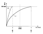
- the solid line L1 in FIG. 3 is the case of the first embodiment, and the two-dot chain line L0 is the case of the comparative example.
- the “tank sealing pressure” is a threshold value of the tank internal pressure that closes the sealing valve 48 and maintains the fuel tank 14 in a sealed state.
- the control device 32 maintains the closing valve 48 in a closed state. 48 is opened.
- the “valve opening limit” in this graph means that when the flow rate of the gas flowing through the communication pipe 20 is less than the valve opening limit, the full tank regulating valve 24 is opened, but the flow rate exceeding the valve opening limit. Then, the flow rate may cause the full tank regulating valve 24 to be closed.
- the flow rate increases as the tank internal pressure increases.
- the amount of increase in the flow rate accompanying the increase in the tank internal pressure is large (abruptly increases).
- the flow rate reaches the valve opening limit before the tank internal pressure reaches the tank closing pressure. Then, when the flow rate reaches the valve opening limit, the pressure difference between the upper and lower sides of the float 44 also increases, and the full tank regulating valve 24 may be closed.
- the control device 32 opens the fuel lid 28, so that the fueling operator can remove the fuel cap 26 and supply fuel to the fuel tank 14.
- the control device 32 opens the closing valve 48 (“pressure release”) in order to suppress an excessive increase in the tank internal pressure.
- pressure release In the fuel tank structure of the comparative example, if the closing valve 48 is opened in a state where the tank internal pressure exceeds the tank closing pressure, the flow rate exceeds the valve opening limit, so that the full tank regulating valve 24 may be closed. .
- the flow rate does not reach the valve opening limit even if the tank internal pressure reaches the tank sealing pressure. Since the full tank regulating valve 24 is not closed, the gas in the fuel tank 14 can flow from the communication pipe 20 to the canister 18 to depressurize the fuel tank 14.
- the opening cross-sectional area of the fixed orifice hole 54 in order to limit the flow rate when the tank internal pressure is high.
- the full orifice regulating valve 24 is not closed when the blocking valve 48 is opened, and the fixed orifice hole 54 is provided so that the flow rate of the communication pipe 20 can be sufficiently secured when the tank internal pressure is reduced or when fueling. It is preferable to set the opening cross-sectional area.
- FIG. 4 and 5 show a fuel tank structure 70 according to a second embodiment of the present invention in a partially enlarged sectional view in the vicinity of the full tank regulating valve 24 and the vicinity thereof.
- the structure of the orifice member is different from that of the first embodiment.
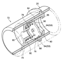
- FIG. 6 is an enlarged view in which the orifice member 72 of the second embodiment is partially broken together with the communication pipe 20.
- the orifice member 72 of the second embodiment includes a first orifice plate 74, a second orifice plate 76, and a compression coil spring 78.
- a first orifice hole 80 is formed in the first orifice plate 74.
- the opening cross-sectional area of the first orifice hole 80 is set so that the flow rate of the communication pipe 20 can be sufficiently secured when the fuel tank 14 is supplied with fuel or when pressure is released.
- a cylindrical cylindrical extension portion 84 that is in close contact with the inner peripheral surface of the communication pipe 20 extends, and further from the tip of the cylindrical extension portion 84 toward the radially inner side.
- An annular stopper piece 86 is extended.
- the second orifice plate 76 is reduced in diameter by cutting out a plurality of locations (four locations in the illustrated example) on the outer periphery of the disc portion 88, so that the second orifice plate 76 extends in the plate thickness direction. It is a notch portion 94 that communicates (penetrates).
- the notch 94 is an example of a communication part.
- a portion where the notch 94 is not formed is a plurality (four in the illustrated example) of square pieces 90. The tip of the square piece 90 is in contact with the inner peripheral surface of the cylindrical extension 84.
- the space between the plurality of square pieces 90 is the notch portion 94 that communicates the second orifice plate 76 in the thickness direction, so that the gap between the second orifice plate 76 and the cylindrical extension portion 84 is between.
- a gap G3 is formed.
- the second orifice plate 76 is movable between the first orifice plate 74 and the stopper piece 86 in the arrow M1 direction and in the opposite direction.
- a compression coil spring 78 is disposed between the first orifice plate 74 and the second orifice plate 76.
- the compression coil spring 78 urges the second orifice plate 76 toward the stopper piece 86.
- the movement of the second orifice plate 76 toward the full tank regulating valve 24 is regulated by the square piece 90 hitting the stopper piece 86.
- the urging force of the compression coil spring 78 is a predetermined value (see the valve closing point TP shown in FIG. 7) in which the tank internal pressure applied to the second orifice plate 76 is lower than the tank closing pressure, and the second orifice plate 76 has the first pressure. It is set to move toward the orifice plate 74 side.
- a second orifice hole 82 having a smaller opening cross-sectional area than the first orifice hole 80 is formed in the second orifice plate 76.
- the second orifice hole 82 is also an example of a communication part.
- the first orifice plate 74 is formed with a cylindrical contact piece 92 that surrounds the first orifice hole 80.
- the second orifice plate 76 moves in the arrow M1 direction, the first orifice plate 74 comes into close contact with the contact piece 92 (see FIG. 5).
- the first orifice hole 80 and the notch 94 are closed, so that the location where the gas can move in the orifice member 72 is only in the second orifice hole 82. That is, the substantial flow path cross-sectional area of the communication pipe 20 is locally reduced by the second orifice hole 82, and the flow rate from the fuel tank 14 to the canister 18 is limited.
- the second orifice hole is set so that the flow rate does not exceed the opening limit of the full tank regulating valve 24.
- An opening sectional area of 82 is set.
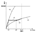
- FIG. 7 qualitatively shows the relationship between the tank internal pressure and the flow rate in the second embodiment.
- a curve L3 indicated by a broken line in FIG. 7 indicates the relationship between the tank internal pressure and the flow rate in a state where the second orifice plate 76 is in close contact with the contact piece 92 as described above.
- a curve L4 indicated by a two-dot chain line indicates a relationship between the tank internal pressure and the flow rate when the second orifice plate 76 is separated from the contact piece 92 (see FIG. 4).
- the fuel tank 14 can be sealed by closing the blocking valve 48 (see FIG. 1 shown as the first embodiment). is there. At this time, no gas flows through the communication pipe 20, and there is no pressure difference between the canister 18 side and the fuel tank 14 side of the orifice member 72, so the second orifice plate 76 is urged by the urging force of the compression coil spring 78. , At a position spaced from the contact piece 92.
- the control device 32 opens the closing valve 48.
- the gas in the fuel tank 14 can move to the canister 18.
- the second orifice plate 76 does not move to the first orifice plate 74 side. Since the flow rate does not exceed the opening limit of the full tank restriction valve 24, the full tank restriction valve 24 is not closed, and the gas in the fuel tank 14 moves to the canister 18 through the communication pipe 20.
- the relationship between the tank internal pressure and the flow rate at this time is the relationship indicated by the curve L4 in FIG.
- the tank internal pressure of the fuel tank 14 gradually decreases as shown by the solid line L6. Then, when the tank internal pressure decreases to the valve opening point HP shown in FIG. 7, the second orifice plate 76 is separated from the contact piece 92. As a result, the substantial flow path cross-sectional area of the communication pipe 20 increases, so that the relationship between the tank internal pressure and the flow rate changes to the relationship indicated by the curve L4, and smooth gas movement from the fuel tank 14 to the canister 18 is achieved. It becomes possible. Then, the control device 32 opens the fuel lid 28 in a state where the tank internal pressure of the fuel tank 14 has dropped below a predetermined value. If the fuel lid 28 is opened, the refueling operator can remove the fuel cap 26 from the refueling port 16H and refuel.
- the control device 32 controls the sealing valve 48 in order to suppress an excessive increase in the tank internal pressure. It is often controlled to open the valve (perform “pressure release”). Since the second orifice plate 76 comes into close contact with the contact piece 92 before the tank internal pressure reaches the tank closing pressure, the full tank regulating valve 24 is not closed. The gas in the fuel tank 14 can flow from the communication pipe 20 to the canister 18 to depressurize the fuel tank 14.
- the substantial flow path cross-sectional area of the communication pipe 20 is reduced when the full tank restriction valve 24 is prevented from being closed while the tank internal pressure is high. 14 to enable smooth fuel movement from 14 to canister 18.
- a complicated mechanism for changing the cross-sectional area of the communication pipe 20 is not required, and the structure is highly reliable.
- the shape of the second orifice plate is not limited to the above.
- a configuration in which one or a plurality of communication holes 104 are formed in the vicinity of the outer periphery of the disc portion 88 as in the second orifice plate 102 shown in FIG. 8A may be used.
- the communication hole 104 is formed on the radially outer side of the contact piece 92 in a state of being in close contact with the contact piece 92, and is an example of a communication portion. For this reason, if the second orifice plate 102 is separated from the contact piece 92, the gas can move through the communication hole 104, and the substantial flow path cross-sectional area of the communication pipe 20 increases. When the orifice plate 102 is brought into close contact with the contact piece 92, gas flow through the communication hole 104 becomes impossible.
- a long hole 108 is formed along the diameter of the disc portion 88.
- the vicinity of both ends in the longitudinal direction of the long hole 108 is formed radially outside the contact piece 92, and is an example of a communication portion.
- the gas can be moved through the entire long hole 108, and the substantial flow path cross-sectional area of the communication pipe 20 is increased.
- gas flow through the vicinity of both ends in the longitudinal direction of the long hole 108 becomes impossible.
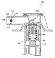
- FIG. 9 and 10 show a fuel tank structure 110 according to a third embodiment of the present invention in a partially enlarged sectional view in the vicinity of the full tank regulating valve 24 and its vicinity.
- the structure of a flow suppression member differs from 1st Embodiment and 2nd Embodiment.
- FIG. 11 is an enlarged view in which the flow suppressing member 112 of the third embodiment is partially broken together with the communication pipe 20.
- a rotation shaft 114 orthogonal to the gas flow direction is provided inside the communication pipe 20.
- a rotating member 116 is rotatably attached to the rotating shaft 114.
- the rotating member 116 includes a substantially circular circular disc portion 118 having a diameter smaller than the inner diameter of the communication pipe 20 and a substantially cylindrical cylindrical portion 120 extending in the radial direction of the disc portion 118 at the center of the circular disc portion 118. And have.
- the disc 118 moves between a valve opening posture inclined or parallel to the gas flow direction (arrow F1 direction) and a valve closing posture perpendicular to the flow direction.
- the rotating member 116 rotates. This rotation is limited by a stopper projection 122 formed on the inner peripheral surface of the communication pipe 20.
- the disc part 118 is formed with a notch part 118K in which the outer peripheral part is notched linearly. Even if the disc portion 118 is in the valve-closed posture, the gas can flow through the gap between the notch portion 118K and the communication pipe 20 or G1. However, the flow passage cross-sectional area of the communication pipe 20 in this case is smaller than that when the disc portion 118 is in the valve opening posture.
- the area of the lower part of the disk part 118 than the cylindrical part 120 is made larger than the area of the upper part.
- a spring 124 is interposed between the rotating shaft 114 and the cylindrical portion 120, and the rotating member 116 is urged to rotate to a valve opening posture.
- the communication pipe 20 is filled with gas. Not flowing.
- the rotating member 116 is maintained in the valve opening posture by the urging force of the spring 124.
- the control device 32 opens the block valve 48 and allows the gas in the fuel tank 14 to move to the canister 18. At this time, if the tank internal pressure does not reach the level of rotating the rotating member 116 to the valve closing posture, the rotating member 116 maintains the valve opening posture. The flow rate does not exceed the valve opening limit FM of the full tank restriction valve 24 and the full tank restriction valve 24 is not closed, so that the gas in the fuel tank 14 moves to the canister 18 through the communication pipe 20.
- the rotating member 116 rotates against the biasing force of the spring 124 to the valve closing posture. Since the substantial flow path cross-sectional area of the communication pipe 20 is reduced, the flow of gas in the communication pipe 20 moving from the fuel tank 14 to the canister 18 is suppressed, and the full tank regulating valve 24 is closed. It is suppressed. Then, the gas in the fuel tank 14 moves to the canister 18 through the communication pipe 20, and the tank internal pressure gradually decreases.
- FIGS. 12 and 13 show a fuel tank structure 130 according to the fourth embodiment of the present invention in a partially enlarged sectional view in the vicinity of the full tank regulating valve 24 and the vicinity thereof.
- the structure of a flow suppression member differs from 1st Embodiment and 2nd Embodiment.
- the communication pipe 20 is provided with a drive shaft 132 in a direction orthogonal to the gas flow direction.
- One end side (upper side in the illustrated example) of the drive shaft 132 passes through the communication pipe 20, and a drive motor 134 controlled by the control device 32 (see FIG. 1) is attached.
- a circular rotating plate 136 is attached to the drive shaft 132.
- the diameter of the rotating plate 136 is slightly smaller than the inner diameter of the communication pipe 20.
- the rotating plate 136 has a valve closing posture (see FIG. 13) in which the normal line of the rotating plate 136 matches the gas flow direction (arrow F1 direction) of the communication pipe 20, and the normal line is inclined with respect to the flow direction. It is rotated by the drive motor 134 so that it can take the valve opening posture (see FIG. 12).
- the rotating plate 136 is opened when the fuel tank 14 is sealed by closing the block valve 48 (see FIG. 1 shown as the first embodiment). Is maintained.
- the control is performed when the tank internal pressure detected by the tank internal pressure sensor 36 has not reached the level at which the full tank regulating valve 24 is closed.
- the device 32 controls the drive motor 134 to maintain the rotating plate 136 in the valve opening posture as shown in FIG. The flow rate does not exceed the opening limit of the full tank restriction valve 24 and the full tank restriction valve 24 is not closed, so that the gas in the fuel tank 14 moves to the canister 18 through the communication pipe 20.
- the control device 32 drives the drive motor 134 to rotate the rotating plate 136 to the valve closing posture as shown in FIG. Since the substantial flow path cross-sectional area of the communication pipe 20 is reduced, the flow of gas in the communication pipe 20 moving from the fuel tank 14 to the canister 18 is suppressed. After that, the control device 32 opens the blocking valve 48 and moves the gas in the fuel tank 14 to the canister 18, so that the situation where the full tank regulating valve 24 is closed is suppressed.
- the control device 32 drives the drive motor 134 to bring the rotating plate 136 into the valve opening posture as shown in FIG. And rotate. Since the substantial flow path cross-sectional area of the communication pipe 20 becomes large, smooth gas movement from the fuel tank 14 to the canister 18 becomes possible. Since the control device 32 opens the fuel lid 28 in a state where the tank internal pressure of the fuel tank 14 is lowered to a predetermined value or less, it is possible to supply fuel to the fuel tank 14.
- the control device 32 when performing pressure relief, first, the control device 32 opens the closing valve 48 in a state where the rotary plate 136 is in the valve closing posture, and the full tank regulation is performed. The pressure in the fuel tank 14 is reduced with the valve 24 closed.
- a configuration in which the length of the communication pipe 20 is increased can be considered.
- the communication pipe 20 is lengthened, it is necessary to avoid interference with surrounding members, and the degree of freedom in the arrangement of the fuel tank structure is reduced.
- Fuel tank structure 14
- Fuel tank 18 Canister 20
- Communication pipe 24
- Sealing valve 52
- Orifice member 70
- Fuel Tank Structure 72
- Orifice Member (Flow Suppression Member) 74
- First orifice plate 76
- Second orifice plate 78
- Compression coil spring biasing member, variable mechanism
- First orifice hole 82
- Second orifice hole (communication part)
- Notch communication part
- 2nd orifice plate 104
- communication hole communication part
- 2nd orifice plate 108
- long hole 110
- Fuel tank structure 112 Flow restricting member 124
- Fuel tank structure 134
- Drive motor variable mechanism
Landscapes
- Engineering & Computer Science (AREA)
- Chemical & Material Sciences (AREA)
- Combustion & Propulsion (AREA)
- Mechanical Engineering (AREA)
- General Engineering & Computer Science (AREA)
- Life Sciences & Earth Sciences (AREA)
- Sustainable Development (AREA)
- Sustainable Energy (AREA)
- Transportation (AREA)
- Supplying Secondary Fuel Or The Like To Fuel, Air Or Fuel-Air Mixtures (AREA)
- Cooling, Air Intake And Gas Exhaust, And Fuel Tank Arrangements In Propulsion Units (AREA)
Abstract
Description
2012年11月27日に出願された日本国特許出願 2012-259080号の開示は、その全体が参照により本明細書に取り込まれる。
14 燃料タンク
18 キャニスタ
20 連通配管
24 満タン規制バルブ
44 フロート
48 封鎖弁
52 オリフィス部材(流動抑制部材)
70 燃料タンク構造
72 オリフィス部材(流動抑制部材)
74 第1オリフィス板
76 第2オリフィス板
78 圧縮コイルスプリング(付勢部材、可変機構)
80 第1オリフィス孔
82 第2オリフィス孔(連通部)
94 切欠部(連通部)
102 第2オリフィス板
104 連通孔(連通部)
106 第2オリフィス板
108 長孔(連通部)
110 燃料タンク構造
112 流動制限部材
124 スプリング(可変機構)
130 燃料タンク構造
134 駆動モータ(可変機構)
138 流動抑制部材
Claims (4)
- 内部に燃料を収容可能な燃料タンクと、
前記燃料タンク内の蒸発燃料を吸着剤により吸着すると共に蒸発燃料吸着後の気体を大気開放するキャニスタと、
前記燃料タンク内に設けられ、前記燃料タンク内の燃料液面があらかじめ設定された満タン液位に達するとフロートが燃料に浮くことで閉弁する満タン規制バルブと、
前記満タン規制バルブを介して前記燃料タンクと前記キャニスタとを連通する連通配管と、
前記連通配管に設けられ制御により連通配管を開閉可能な封鎖弁と、
前記連通配管に設けられ連通配管の気体の流動を抑制する流動抑制部材と、
を有する燃料タンク構造。 - 前記流動抑制部材が、前記連通配管の流路断面積を変更可能とする可変機構を有する請求項1に記載の燃料タンク構造。
- 前記流動抑制部材が、前記連通配管の流路断面積を局所的に小さくするオリフィス部材を有する請求項2に記載の燃料タンク構造。
- 前記オリフィス部材が、
前記連通配管の内部に密着され連通配管の内径よりも小さい内径の第1オリフィス孔を有する第1オリフィス板と、
前記第1オリフィス板よりも前記満タン規制バルブ側に配置され第1オリフィス板に接触すると前記第1オリフィス孔の一部を閉塞すると共に、第1オリフィス板への接触状態で一部が閉塞される1又は複数の連通部を備えた第2オリフィス板と、を備え、
前記可変機構が、
前記第2オリフィス板を前記第1オリフィス板から離間するように前記満タン規制バルブ側へ付勢し、前記燃料タンクから前記第2オリフィス板に作用した所定値以上のタンク内圧により前記第1オリフィス板側へ前記第2オリフィス板を移動可能とする付勢部材を有する請求項3に記載の燃料タンク構造。
Priority Applications (3)
| Application Number | Priority Date | Filing Date | Title |
|---|---|---|---|
| JP2014509537A JP5817924B2 (ja) | 2012-11-27 | 2013-11-20 | 燃料タンク構造 |
| CA2892826A CA2892826C (en) | 2012-11-27 | 2013-11-20 | Fuel tank structure |
| US14/646,489 US10029559B2 (en) | 2012-11-27 | 2013-11-20 | Fuel tank structure |
Applications Claiming Priority (2)
| Application Number | Priority Date | Filing Date | Title |
|---|---|---|---|
| JP2012-259080 | 2012-11-27 | ||
| JP2012259080 | 2012-11-27 |
Publications (1)
| Publication Number | Publication Date |
|---|---|
| WO2014084103A1 true WO2014084103A1 (ja) | 2014-06-05 |
Family
ID=50827744
Family Applications (1)
| Application Number | Title | Priority Date | Filing Date |
|---|---|---|---|
| PCT/JP2013/081321 Ceased WO2014084103A1 (ja) | 2012-11-27 | 2013-11-20 | 燃料タンク構造 |
Country Status (4)
| Country | Link |
|---|---|
| US (1) | US10029559B2 (ja) |
| JP (1) | JP5817924B2 (ja) |
| CA (1) | CA2892826C (ja) |
| WO (1) | WO2014084103A1 (ja) |
Cited By (1)
| Publication number | Priority date | Publication date | Assignee | Title |
|---|---|---|---|---|
| JP2016151189A (ja) * | 2015-02-16 | 2016-08-22 | 株式会社デンソー | 2段切替弁 |
Families Citing this family (4)
| Publication number | Priority date | Publication date | Assignee | Title |
|---|---|---|---|---|
| JP6945310B2 (ja) * | 2017-03-22 | 2021-10-06 | 浜名湖電装株式会社 | 燃料タンクシステム |
| WO2019086147A2 (en) * | 2017-11-03 | 2019-05-09 | Eaton Intelligent Power Limited | Evaporative emissions control system and method for isolating fuel tank from a purge canister |
| EP3798030B1 (en) | 2019-09-25 | 2022-08-03 | Ningbo Geely Automobile Research & Development Co. Ltd. | Air conditioning system for a vehicle |
| US11441498B1 (en) * | 2021-07-01 | 2022-09-13 | Ford Global Technologies, Llc | Method and system for reducing evaporative emissions |
Citations (4)
| Publication number | Priority date | Publication date | Assignee | Title |
|---|---|---|---|---|
| US20110220071A1 (en) * | 2010-03-11 | 2011-09-15 | Honda Motor Co., Ltd. | Evaporated fuel treatment apparatus |
| US20110253110A1 (en) * | 2010-04-15 | 2011-10-20 | Toyota Jidosha Kabushiki Kaisha | Vaporized fuel processing device for internal combustion engine |
| JP2011256778A (ja) * | 2010-06-09 | 2011-12-22 | Honda Motor Co Ltd | 蒸発燃料処理装置 |
| JP2012154299A (ja) * | 2011-01-28 | 2012-08-16 | Honda Motor Co Ltd | 蒸発燃料処理装置 |
Family Cites Families (8)
| Publication number | Priority date | Publication date | Assignee | Title |
|---|---|---|---|---|
| US4867200A (en) * | 1988-06-30 | 1989-09-19 | Markley George L | Unidirectional fluid flow check valve assembly |
| US5280805A (en) * | 1993-01-19 | 1994-01-25 | Skoglund Paul K | Flow control valve having adjustable sleeve for varying flow rate |
| JP3515648B2 (ja) | 1995-10-13 | 2004-04-05 | 本田技研工業株式会社 | 蒸発燃料処理装置 |
| JP3705398B2 (ja) * | 1997-12-26 | 2005-10-12 | スズキ株式会社 | 内燃機関の蒸発燃料制御装置 |
| JP5232079B2 (ja) | 2009-06-04 | 2013-07-10 | トヨタ自動車株式会社 | 蒸発燃料処理装置 |
| JP2011161974A (ja) * | 2010-02-05 | 2011-08-25 | Toyota Motor Corp | 燃料タンク、並びに同燃料タンクを具備する蒸発燃料処理装置 |
| CO6340185A1 (es) * | 2010-05-24 | 2011-11-21 | Gutierrez Ismael Hernan Riano | Regulador economizador automático de flujo, de un fluído líquido |
| CN103328803B (zh) * | 2011-01-21 | 2016-01-13 | 伊顿公司 | 用于高压应用的具有集成的浮阀的隔离阀 |
-
2013
- 2013-11-20 CA CA2892826A patent/CA2892826C/en active Active
- 2013-11-20 JP JP2014509537A patent/JP5817924B2/ja not_active Expired - Fee Related
- 2013-11-20 US US14/646,489 patent/US10029559B2/en active Active
- 2013-11-20 WO PCT/JP2013/081321 patent/WO2014084103A1/ja not_active Ceased
Patent Citations (6)
| Publication number | Priority date | Publication date | Assignee | Title |
|---|---|---|---|---|
| US20110220071A1 (en) * | 2010-03-11 | 2011-09-15 | Honda Motor Co., Ltd. | Evaporated fuel treatment apparatus |
| CN102192052A (zh) * | 2010-03-11 | 2011-09-21 | 本田技研工业株式会社 | 蒸发燃料处理装置 |
| US20110253110A1 (en) * | 2010-04-15 | 2011-10-20 | Toyota Jidosha Kabushiki Kaisha | Vaporized fuel processing device for internal combustion engine |
| JP2011226308A (ja) * | 2010-04-15 | 2011-11-10 | Toyota Motor Corp | 内燃機関の蒸発燃料処理装置 |
| JP2011256778A (ja) * | 2010-06-09 | 2011-12-22 | Honda Motor Co Ltd | 蒸発燃料処理装置 |
| JP2012154299A (ja) * | 2011-01-28 | 2012-08-16 | Honda Motor Co Ltd | 蒸発燃料処理装置 |
Cited By (1)
| Publication number | Priority date | Publication date | Assignee | Title |
|---|---|---|---|---|
| JP2016151189A (ja) * | 2015-02-16 | 2016-08-22 | 株式会社デンソー | 2段切替弁 |
Also Published As
| Publication number | Publication date |
|---|---|
| CA2892826A1 (en) | 2014-06-05 |
| US20150306951A1 (en) | 2015-10-29 |
| US10029559B2 (en) | 2018-07-24 |
| CA2892826C (en) | 2016-07-12 |
| JPWO2014084103A1 (ja) | 2017-01-05 |
| JP5817924B2 (ja) | 2015-11-18 |
Similar Documents
| Publication | Publication Date | Title |
|---|---|---|
| JP5902637B2 (ja) | 燃料タンク構造 | |
| JP5400669B2 (ja) | 蒸発燃料処理装置 | |
| US8944100B2 (en) | Isolation valve with fast depressurization for high-pressure fuel tank | |
| US8622088B2 (en) | Solenoid valves capable of controlling valve-opening area | |
| JP5817924B2 (ja) | 燃料タンク構造 | |
| JP5299565B2 (ja) | 燃料タンクシステム | |
| JP6287809B2 (ja) | 燃料タンクシステム | |
| JP5913024B2 (ja) | 蒸発燃料処理装置 | |
| JP6128084B2 (ja) | 燃料タンクの給油部構造 | |
| JP5817536B2 (ja) | 燃料タンクシステム | |
| JP7027951B2 (ja) | 車両の燃料タンク装置 | |
| JP5810942B2 (ja) | 燃料タンクシステム | |
| JP4918150B2 (ja) | 制御バルブの制御方法 | |
| JP7516311B2 (ja) | 燃料タンク構造 | |
| JP5807527B2 (ja) | 燃料タンクシステム | |
| JP2013155636A (ja) | 燃料タンクシステム及び燃料タンクシステム異常検知方法 | |
| JP4468769B2 (ja) | 蒸発燃料吸着装置 | |
| JP5786750B2 (ja) | 燃料タンクシステム | |
| JP5234014B2 (ja) | 燃料タンクシステム | |
| JP2013167177A (ja) | 燃料タンクシステム | |
| JP2013142314A (ja) | 燃料タンクシステム | |
| JP5849755B2 (ja) | 燃料タンクシステム | |
| JP2012097658A (ja) | 燃料タンクシステム | |
| JP2013256911A (ja) | 燃料タンクシステム |
Legal Events
| Date | Code | Title | Description |
|---|---|---|---|
| ENP | Entry into the national phase |
Ref document number: 2014509537 Country of ref document: JP Kind code of ref document: A |
|
| 121 | Ep: the epo has been informed by wipo that ep was designated in this application |
Ref document number: 13858921 Country of ref document: EP Kind code of ref document: A1 |
|
| WWE | Wipo information: entry into national phase |
Ref document number: 14646489 Country of ref document: US |
|
| ENP | Entry into the national phase |
Ref document number: 2892826 Country of ref document: CA |
|
| NENP | Non-entry into the national phase |
Ref country code: DE |
|
| 122 | Ep: pct application non-entry in european phase |
Ref document number: 13858921 Country of ref document: EP Kind code of ref document: A1 |