WO2014081019A1 - プリンタヘッド洗浄装置及びインクジェット印刷装置 - Google Patents
プリンタヘッド洗浄装置及びインクジェット印刷装置 Download PDFInfo
- Publication number
- WO2014081019A1 WO2014081019A1 PCT/JP2013/081555 JP2013081555W WO2014081019A1 WO 2014081019 A1 WO2014081019 A1 WO 2014081019A1 JP 2013081555 W JP2013081555 W JP 2013081555W WO 2014081019 A1 WO2014081019 A1 WO 2014081019A1
- Authority
- WO
- WIPO (PCT)
- Prior art keywords
- cleaning
- vibration
- printer head
- frequency
- ink
- Prior art date
- Legal status (The legal status is an assumption and is not a legal conclusion. Google has not performed a legal analysis and makes no representation as to the accuracy of the status listed.)
- Ceased
Links
Images



Classifications
-
- B—PERFORMING OPERATIONS; TRANSPORTING
- B41—PRINTING; LINING MACHINES; TYPEWRITERS; STAMPS
- B41J—TYPEWRITERS; SELECTIVE PRINTING MECHANISMS, i.e. MECHANISMS PRINTING OTHERWISE THAN FROM A FORME; CORRECTION OF TYPOGRAPHICAL ERRORS
- B41J2/00—Typewriters or selective printing mechanisms characterised by the printing or marking process for which they are designed
- B41J2/005—Typewriters or selective printing mechanisms characterised by the printing or marking process for which they are designed characterised by bringing liquid or particles selectively into contact with a printing material
- B41J2/01—Ink jet
- B41J2/135—Nozzles
- B41J2/165—Prevention or detection of nozzle clogging, e.g. cleaning, capping or moistening for nozzles
- B41J2/16517—Cleaning of print head nozzles
- B41J2/16552—Cleaning of print head nozzles using cleaning fluids
-
- B—PERFORMING OPERATIONS; TRANSPORTING
- B08—CLEANING
- B08B—CLEANING IN GENERAL; PREVENTION OF FOULING IN GENERAL
- B08B3/00—Cleaning by methods involving the use or presence of liquid or steam
- B08B3/04—Cleaning involving contact with liquid
- B08B3/10—Cleaning involving contact with liquid with additional treatment of the liquid or of the object being cleaned, e.g. by heat, by electricity or by vibration
- B08B3/102—Cleaning involving contact with liquid with additional treatment of the liquid or of the object being cleaned, e.g. by heat, by electricity or by vibration with means for agitating the liquid
-
- B—PERFORMING OPERATIONS; TRANSPORTING
- B41—PRINTING; LINING MACHINES; TYPEWRITERS; STAMPS
- B41J—TYPEWRITERS; SELECTIVE PRINTING MECHANISMS, i.e. MECHANISMS PRINTING OTHERWISE THAN FROM A FORME; CORRECTION OF TYPOGRAPHICAL ERRORS
- B41J2/00—Typewriters or selective printing mechanisms characterised by the printing or marking process for which they are designed
- B41J2/005—Typewriters or selective printing mechanisms characterised by the printing or marking process for which they are designed characterised by bringing liquid or particles selectively into contact with a printing material
- B41J2/01—Ink jet
- B41J2/135—Nozzles
- B41J2/165—Prevention or detection of nozzle clogging, e.g. cleaning, capping or moistening for nozzles
- B41J2/16517—Cleaning of print head nozzles
- B41J2002/16567—Cleaning of print head nozzles using ultrasonic or vibrating means
Definitions
- the present invention relates to a printer head cleaning apparatus and an ink jet printing apparatus for cleaning a nozzle surface of a printer head.
- FIG. 11 is a block diagram showing an example of a conventional inkjet head cleaning apparatus.
- the inkjet head cleaning apparatus 500 is configured such that an ultrasonic cleaning machine 52 is provided below the head cleaning container 51 and the cleaning liquid 53 is stored in the head cleaning container 51.
- the frequency converter (not shown) can change the frequency of the ultrasonic cleaner 52.
- the inkjet head 60 is immersed in the head cleaning container 51, and the inkjet head 60 is cleaned while changing its frequency by the ultrasonic cleaner 52.
- the dirt is removed only by the ultrasonic wave, but there is a problem that the dirt that cannot be removed by the ultrasonic wave alone actually remains on the nozzle surface.
- dirt on the nozzle surface can cause nozzle clogging and ink droplet flying.
- a printer head cleaning apparatus has a cleaning tank for storing a cleaning solution for immersing the nozzle surface of the printer head, and a plurality of fine ends provided in the cleaning tank and in contact with the nozzle surface of the printer head.
- the brush portion is provided with cleaning vibration adding means for applying ultrasonic vibration having a cleaning frequency for decomposing the dirt of the cleaning liquid.
- the fine end portion of the brush portion (for example, the brush tip) is brought into contact with the nozzle surface.
- a piezoelectric element or the like which is a washing vibration adding means
- the dirt on the nozzle surface is decomposed and removed by the ultrasonic vibration, and the fine end portion of the brush part in contact with the nozzle surface vibrates. Remove persistent stains on the surface.
- the fine end portion scratches the nozzle surface and removes dirt on the nozzle surface. This makes it possible to reliably remove dirt that is difficult to remove with only ultrasonic waves.
- the washing vibration adding means is a piezoelectric element or a motor.
- the brush portion may have a base portion that holds the numerous fine end portions, and the cleaning vibration adding means may be provided on the base portion.
- the ultrasonic vibration can be directly applied to the base by providing the cleaning vibration adding means at the base (rotating shaft or the like), and the vibration is well transmitted to the fine end of the brush. Thereby, the stain
- a drive unit that moves the entire brush unit and functions as the cleaning vibration adding unit may be provided.
- the ink jet printing apparatus applies a voltage of a predetermined frequency to the printer head cleaning device and the vibration applying means for applying vibration to the vibration member facing the ink chamber communicating with the nozzle of the printer head. Then, printing is performed by ejecting ink from the nozzles by applying a voltage to the vibration applying means, and in the cleaning mode, the frequency of the ink chamber and nozzle cleaning frequency different from the frequency for printing is vibrated. Voltage applying means for applying to the adding means.
- the cleaning frequency is an effective frequency for removing the dirt in the head, and when applied to the vibration applying means, the vibration of the frequency is transmitted into the head and the dirt in the head is removed.
- the cleaning frequency voltage may be applied continuously for a longer time than the voltage application time during printing. As a result, the stain can be peeled off or decomposed from the wall surface of the ink chamber.
- FIG. 1 is a configuration diagram illustrating an ink jet printer according to Embodiment 1 of the present invention.
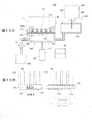
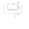
- FIG. 2A and 2B are block diagrams showing a capping station of the ink jet printer shown in FIG. It is a block diagram which shows the capping station of the inkjet printer shown in FIG. It is a block diagram which shows the capping station of the inkjet printer shown in FIG. It is a block diagram which shows the wiper unit of the inkjet printer shown in FIG. It is a block diagram which shows the controller of this inkjet printer. It is a top view which shows a cap. It is a flowchart which shows operation
- 9A to 9D are explanatory views showing the operation of the ink jet printer according to Embodiment 2 of the present invention.
- 10A and 10B are configuration diagrams showing an ink jet printer according to Embodiment 3 of the present invention. It is a block diagram which shows an example of the conventional inkjet head cleaning apparatus.
- FIG. 1 is a block diagram showing an ink jet printer according to Embodiment 1 of the present invention.
- 2A, FIG. 2B, FIG. 3, and FIG. 4 are block diagrams showing the capping station of the ink jet printer shown in FIG.
- FIG. 5 is a block diagram showing a wiper unit of the ink jet printer shown in FIG.
- FIG. 6 is a block diagram showing the controller of this ink jet printer.
- FIG. 7 is a plan view showing a cap of the capping station.
- the inkjet printer 100 includes a printer head 1, a carriage 151 that holds the printer head 1 and moves in the main scanning direction, a platen or table 152 on which the medium M is placed, and a printing area of the medium M in the main scanning direction.
- a capping station 160 provided, a wiper unit 161 provided adjacent to the capping station 160, and a controller 20 for controlling the operation of the ink jet printer are included.
- the printer head 1 includes a main body 2, a nozzle 3 having a discharge port on a nozzle surface 3 a, an introduction port 5 connected to the nozzle 3 via a groove 4, and an upper portion of the nozzle 3.
- the ink chamber 6 is formed, and the piezoelectric element 8 is formed on the diaphragm film 7 formed on the ink chamber 6 so as to face the ink chamber 6.
- a lower electrode 8a and an upper electrode 8b are laminated.
- the lower electrode 8 a and the upper electrode 8 b are connected to a power source 9 that supplies power to the piezoelectric element 8.
- a power source 9 that supplies power to the piezoelectric element 8.
- one nozzle 3 is schematically illustrated in an enlarged manner, but a large number of the nozzles 3 are formed on the nozzle surface 3 a of the printer head 1.
- the power source 9 is connected to a driver circuit 12 that supplies a driving voltage to the piezoelectric element 8.
- the driver circuit 12 is controlled by the controller 20.
- the capping station 160 includes a cap 103 serving as a cleaning tank that stores the cleaning liquid 104, and an actuator 102 that is connected to the controller 20 and moves the cap 103 up and down.
- a pump 11 made of a tubing pump is connected to the cap 103.
- the pump 11 is connected to a cleaning liquid tank 105 that stores the cleaning liquid 104 via a tube.
- the cap 103 is usually placed over the printer head 1 to prevent the printer head 1 from drying.
- the capping station 160 has a rotating brush 50 in the cap 103.
- a hollow rotating shaft 51 is pivotally supported on the side wall 103 a of the cap 103, and one end 51 a thereof is connected to the motor 52.
- the rotating brush 50 is provided with a large number of hairs 53 in the circumferential direction of a rotating shaft 51 as a base, and has a cylindrical shape as a whole.
- the bristles of the hair 53 are sharp.
- the bristles 53 of the rotating brush 50 are made of polypropylene, polyethylene terephthalate, polyester, nylon, aramid, or the like.
- the rotary brush 50 has a positional relationship in which the bristles of the rotary brush 50 come into contact with the nozzle surface 3 a of the nozzle 3 in a state where the cap 103 is put on the printer head 1.
- the one end 51a of the rotating shaft 51 is engaged with the rotating shaft of the motor 52 through a keyway. Since the hair 53 of the rotating brush 50 becomes a fine end, the nozzle surface 3a can be easily removed by moving in contact with the nozzle surface 3a.
- the rotating shaft 51 is rotatably supported by the bearing of the cap 103.
- the motor 52 is connected to the controller 20.
- the motor 52 is composed of a stepping motor.
- the motor 52 is driven by a driver circuit 54.
- the rotation of the driver circuit 54 is controlled by a drive signal from the brush drive unit 31.
- FIG. 2B is an enlarged view of portions A and B surrounded by a dotted line in FIG. 2A.
- a piezoelectric element 150 is provided at the substantially inner center of the rotating shaft 51.
- An electric wire 152 for energization is connected to the piezoelectric element 150.
- the electric wire 152 passes through the rotary shaft 51 and is disposed up to the other end 51 b of the rotary shaft 51.
- a disc-shaped lid 153 is provided at the other end 51 b of the rotating shaft 51, and a ring-shaped electrode 154 is formed on the outer surface of the lid 153.
- a cover 133 is provided on the other end 51b.
- a brush 155 is provided inside the cover 133, and the tip of the brush 155 contacts the electrode 154.
- the brush 155 is connected to the driver circuit 156.
- the driver circuit 156 drives the piezoelectric element 150 and is connected to the controller 20.
- an automatic level adjuster 180 is connected to the cap 103.
- the automatic level adjuster 180 includes an adjustment tank 181 connected to the cap 103 and containing the cleaning liquid 104 therein, and a supply tank 183 disposed above the adjustment tank 181.
- a pipe 184 extends downward from the bottom of the supply tank 183, and the tip of the pipe 184 is immersed in the liquid level of the adjustment tank 181.
- the adjustment tank 181 is provided with a communication port 182 that communicates with the atmosphere.
- the automatic level adjuster 180 keeps the liquid level of the cap 103 constant by supplying the cleaning liquid 104 to the cap 103.
- the automatic level adjuster 180 when the liquid level is lowered by supplying the cleaning liquid 104 from the adjustment tank 181, the lower end of the pipe 184 of the supply tank 183 comes out of the liquid level, and air enters from the tip of the pipe 184. The air enters the supply tank 183 through the pipe 184, the pressure of the supply tank 183 increases, the liquid level decreases, and the cleaning liquid is supplied from the pipe 184 to the adjustment tank 181.
- the liquid level of the adjustment tank 181 rises, the lower end of the pipe 184 is immersed below the liquid level, the supply of air from the tip is shut off, and the supply of the cleaning liquid 104 from the supply tank 183 is stopped. By repeating this, the liquid level of the adjustment tank 181 is kept near the tip of the pipe 184.
- the wiper unit 161 includes a container body 113, a wiper device 114 directed into the container body 113, and an actuator 115 that moves the container body 113 up and down.
- the wiper device 114 includes a slider 116 that moves along the nozzle surface 3 a, a long band-like rubber wiper 117 provided on the slider 116, and a sponge layer 118 provided on the wiper 117 in a stacked manner. Is done.
- the slider 116 is moved by an actuator (not shown).
- the inside of the container main body 113 has a structure in which dirt or thickened ink that appears when the nozzle surface 3a is wiped is dropped and collected.
- the controller 20 drives the driver circuit 156 to issue a command to drive the piezoelectric element 150 with the frequency set in the cleaning mode and the cleaning setting unit 21 that sets the voltage and frequency applied to the piezoelectric element 150 in the cleaning mode.
- a control unit 22, a pump control unit 23 that controls driving of the pump 11, a wiping control unit 30 that controls the wiper unit 161, and a brush control unit 31 that controls the rotation of the rotary brush 50 are provided.
- the cleaning setting unit 21 sets the frequency of vibration generated by the piezoelectric element 150 in the cleaning mode in three stages. Specifically, the frequency of vibration generated by the piezoelectric element 150 is set within ⁇ 20% of 28 kHz, 45 kHz, and 100 kHz. The user can select any one of these frequencies or a combination thereof using the cleaning setting unit 21. Further, the frequency can be changed by a washing button 25 displayed on the display means 24 connected to the controller 20. For example, it can be changed to 30 kHz, 120 kHz, or the like. As the display means 24, a touch-type liquid crystal panel or the like is used. Three types of “strong cleaning”, “normal cleaning”, and “fine cleaning” are displayed as the cleaning button 25. “Strong cleaning” is performed at a low frequency of 28 kHz. “Normal cleaning” is assigned to 45 kHz, and “fine cleaning” is assigned to 100 kHz.
- the cleaning button 25 may be a mechanical button.
- a voltage in which the above frequencies are superimposed may be applied.
- the frequency to be superimposed on the piezoelectric element 150 is set by the cleaning setting unit 21.
- the frequency superimposition can be performed in pieces. For example, a voltage of 28 kHz frequency of “strong cleaning” can be applied piecewise while applying a voltage of 100 kHz frequency as “fine cleaning”.
- the pump 11 is driven by a motor 13.
- the cleaning setting unit 21 can set cleaning timing and cleaning time. For example, it can be set to be performed regularly at a predetermined time every other day. In addition, it can be set to be automatically performed when the inkjet printer 100 is activated.
- the frequency may be set so as to change continuously. For example, it can be changed every 1 kHz between 1 kHz and 100 kHz. Further, it may be changed linearly or may be changed according to a predetermined curve characteristic.
- the combination of cleaning strength can be set freely.
- the combination can be set by a screen (not shown) entered from the combination button 26.
- the “strong cleaning” is first performed, “normal cleaning” is performed after a predetermined time, and “fine cleaning” is performed after a predetermined time. “Strong cleaning” is performed only once, and thereafter “normal cleaning” and “fine cleaning” are alternately performed.
- the discharge of the cleaning liquid in the cap 103 is performed by starting the driving of the pump 11 with the discharge button 27.
- FIG. 8 is a flowchart showing the operation of the ink jet printer. Note that the following procedure is executed by a predetermined program.
- the cleaning setting unit 21 sets a frequency used for cleaning (step S1). For example, in order to perform “strong cleaning”, the “strong cleaning” cleaning button 25 displayed on the display means 24 is pressed.
- the user sets a cleaning time by the cleaning setting unit 21 (step S2).
- the cleaning time is displayed by the display means 24.
- the cleaning time can be set in seconds. Note that the cleaning time setting process can be omitted by setting the cleaning time as a default for each cleaning level.
- step S3 when combining a cleaning level with a frequency different from the selected cleaning level (“strong cleaning” is selected in the above) (step S3), the combination button 26 displayed on the display means 24 is pressed (step S4). .
- the screen moves to a combination screen (not shown), and, for example, “fine cleaning” is selected from the cleaning buttons displayed on the combination screen.
- the discharge button 27 can be selected and combined with the cleaning button 25.
- the user sets the cleaning timing by the cleaning setting unit 21 (step S5).
- the cleaning timing is when the operation of the ink jet printer 100 is started or when the operation is stopped. These timings are displayed by the cleaning timing button 28 by the display means 24.
- the controller 20 shifts to a cleaning start time input screen (not shown). The user inputs and sets what time the washing operation is performed during the pause. For example, a setting is made to perform the cleaning operation at midnight.
- the cleaning operation is automatically performed when the power supply 9 is turned on next time.
- the pump 11 is driven by the pump control unit 23 to introduce the cleaning liquid 104 into the cap 103 of the capping station 160.
- the printer head 1 is moved above the cap 103, the cap 103 is lifted by the actuator 102, and is put on the nozzle surface 3a of the printer head 1 (step S7).
- the nozzle surface 3a of the printer head 1 is immersed in the cleaning liquid 104 in the cap 103 as shown in FIG. 2A, FIG. 2B, and FIG.
- the piezoelectric element 150 is ultrasonically vibrated with the set frequency (step S8). Fine bubbles are generated by this ultrasonic vibration, and stains such as highly viscous ink adhering to the nozzle surface 3a are removed by the action of cavitation and acceleration energy. Further, ultrasonic waves act on the hair 53 of the rotating brush 50 to vibrate it. The vibrated hair 53 contacts the nozzle surface 3a and mechanically removes dirt on the surface.
- the wavelength of the high-frequency vibration from the piezoelectric element 150 is shorter than the diameter of the nozzle hole, it enters the nozzle and decomposes the dirt on the inner wall of the nozzle 3. Further, the ultrasonic vibration generated when the hair 53 of the rotating brush 50 vibrates easily enters the nozzle 3 because the hair 53 is located near the nozzle surface 3a.
- the motor 52 is driven together with the addition of the ultrasonic wave to rotate the rotary brush 50.
- the bristles of the rotating brush 50 are pointed and the tip of the rotating brush 50 scratches the nozzle surface 3a by the rotating operation, so that the dirt on the nozzle surface 3a is mechanically peeled off and removed.
- the rotation speed of the rotary brush 50 is, for example, 0.5 rpm to 10 rpm. The dirt thus decomposed or removed diffuses into the cleaning liquid.
- the cleaning liquid in the cap 103 is sucked by the pump 11, and the ink and cleaning liquid in the ink chamber 6 are discharged through the nozzle 3 (step S9).
- the cleaning liquid containing the decomposed dirt is discharged, and new ink is introduced into the ink chamber 6.
- the actuator 102 After discharging the ink, the actuator 102 is driven to lower the cap 103, and the cap 103 is removed from the printer head 1 (step S10).
- step S11 the printer head 1 is moved and positioned again on the wiper unit 161, the actuator 115 is driven to press the wiper 117 against the nozzle surface 3a of the printer head 1, and the slider 116 is moved to wipe the nozzle surface 3a. Is performed (step S11).
- step S12 since ink of another color may be pushed into the nozzle 3 during wiping, the piezoelectric element 8 is driven to perform flushing (step S12), and the ink of another color that has entered the nozzle 3 is ejected. To do.
- This flushing operation is performed with the printer head 1 in the wiper unit 161.
- the ink ejected by flushing falls and accumulates in the container body 113 of the wiper unit 161.
- the cleaning of the printer head 1 in the cleaning mode is completed, and then the printer automatically returns to the normal printing mode.
- the contamination of the nozzle surface 3a can be reliably removed by the application of ultrasonic vibration by the motor 52 and the contact with the rotary brush 50.
- the rotating brush 50 only needs to have a large number of fine end portions that come into contact with the nozzle surface 3a.
- the rotating brush 50 may have a configuration in which a non-woven fabric or a woven fiber is attached to the rotating shaft 51 (not shown).
- the printing piezoelectric element 8 provided in the printer head 1 can be used together with the cleaning by the piezoelectric element 150 and the rotating brush 50 for cleaning.
- the power source 9 and the controller 20 form voltage applying means for applying a voltage having a cleaning frequency to the piezoelectric element 8.
- the cleaning setting unit 21 applies a predetermined cleaning frequency to the piezoelectric element 8.
- the frequency of the voltage applied to the piezoelectric element 8 is set to “strong cleaning” of 28 kHz, “normal cleaning” of 45 kHz, and “fine cleaning” of 100 kHz.
- different frequencies can be selected depending on the type of ink, the specifications of the printer head 1, and the like.
- the user can select any one of these frequencies or a combination thereof using the cleaning setting unit 21.
- the frequency can be changed by a washing button 25 displayed on the display means 24 connected to the controller 20.
- the cleaning setting unit 21 adjusts the amplitude of the diaphragm film 7 by the piezoelectric element 8 by controlling the voltage.
- the controller 20 applies to the piezoelectric element 8 a voltage that provides a frequency and amplitude necessary for ejecting ink from the nozzle 3.
- the cleaning liquid 104 is gradually introduced into the ink chamber 6 by the vibration of the piezoelectric element 8 during cleaning. It is not necessary to replace all the ink in the ink chamber 6 with the cleaning liquid. Since a predetermined ultrasonic vibration is transmitted to the ink in the ink chamber 6, the dirt stuck to the wall surface of the ink chamber 6 is peeled off and decomposed. The cleaning liquid 104 introduced into the ink chamber 6 prevents reattachment to the wall surface by enclosing the decomposed dirt. The nozzle 3 is also cleaned by the operation of the cleaning liquid 104.
- the ink in the ink chamber 6 is discharged through the nozzle 3.
- the ink containing the decomposed dirt is discharged as it is, and new ink is introduced into the ink chamber 6 due to the pressure drop caused by the discharge.
- cavitation occurs in the ink due to vibration in the cleaning mode, and bubbles are generated accordingly.
- the ink containing the bubbles is also discharged as it is, so that air blow caused by the bubbles is prevented.
- the ink chamber 6 can be cleaned directly because the cleaning is performed by the piezoelectric element 8 provided on the diaphragm film 7 provided facing the ink chamber 6. Furthermore, since the inside of the ink chamber 6 is cleaned with the cleaning liquid 104, a high cleaning effect can be obtained.
- step S9 the inside of the cap 103 is sucked by the pump 11 after washing to make a negative pressure, and dirty ink is sucked and discharged from the ink chamber 6 through the nozzle 3, but this suction is performed. Instead, the ink may be positively discharged by supplying ink to the ink chamber 6. Then, the cap 103 is lowered and the cap 103 is removed from the printer head 1 (step S10), and wiping (step S11) and flushing (step S12) are performed as described above. These steps are set by the cleaning setting unit 21 of the controller 20, and the pump 11 and the wiper unit 161 are controlled according to this procedure.
- the cleaning setting unit 21 of the controller 20 has an effect of attenuating high frequency to bubbles with small cavitation. Therefore, when fine bubbles increase, the ink is discharged and then cleaning is performed at the next frequency. May be.
- “strong cleaning” is performed at 28 kHz, ink in which minute bubbles are generated is discharged from the ink chamber 6, and new ink is introduced into the ink chamber 6.
- the cleaning effect is further improved. In particular, if ink is discharged and introduced before high-frequency cleaning, the cleaning effect is improved.
- the discharging operation can be set during “strong cleaning”, “normal cleaning”, and “fine cleaning”.
- the discharging operation is performed through the cap 103 by driving the pump 11.
- FIG. 9C cleaning at a high frequency (100 kHz, which is “fine cleaning”) is performed first, and the frequency at which the influence of bubbles is low (for example, 28 kHz, which is “strong cleaning” at which the frequency is lower than other cleaning times). ), The ink can be washed without discharging the ink and while suppressing the attenuation due to the minute bubbles. Further, as shown in FIG. 9D, it can be performed in the order of “normal cleaning” and “strong cleaning”.
- FIGS. 10A and 10B are configuration diagrams showing an ink jet printer according to Embodiment 3 of the present invention.
- the ink jet printer 250 has substantially the same configuration as that of the ink jet printer 100 according to the first embodiment, except that the piezoelectric element 170 is provided at the end of the drive shaft 173 of the brush 172 and the hole 175 of the base 174 of the brush 172.
- the drive shaft 173 is passed through.
- Other configurations are the same as those of the first embodiment, and thus the description thereof is omitted.
- the piezoelectric element 170 is fixed to the cap 103 by a cover 171. Further, the drive shaft 173 made of metal is joined to the piezoelectric element 170.
- the drive shaft 173 has a rectangular cross section and is disposed in the longitudinal direction in the cap 103. As shown in FIG. 10A, the hole 175 of the base 174 has a rectangular cross section through which the drive shaft 173 can be inserted. This allows the brush 172 to slide without rotating along the drive shaft 173.
- the piezoelectric element 171 applies a wave having a predetermined shape to the drive shaft 173, and reciprocates the base 174 inserted into the drive shaft 173.
- the piezoelectric element 170 is given a signal waveform of a voltage that causes the drive shaft 173 to slowly expand in one direction and rapidly contract in the opposite direction, and the base 174 is reciprocated.
- the base 174 advances in the right direction in the figure by loosening the left side of the mountain waveform of the expansion and contraction displacement, and the base 174 in the left direction in the figure by loosening the right side in the figure. Proceed to These operations are performed by the brush drive unit 31 of the controller 20.
- the frequency applied to the drive shaft 173 is the cleaning frequency shown in the first embodiment. As a result, ultrasonic vibration is transmitted to the cleaning liquid, and the tip of the brush 172 is vibrated.
- the brush 172 reciprocates by a predetermined wave applied to the drive shaft 173, the nozzle surface 3a is scratched by the brush tip of the brush 172, and the dirt adhering to the nozzle surface 3a is mechanically removed. Further, ultrasonic vibration is transmitted from the brush 172 to the cleaning liquid, and the ultrasonic waves enter the nozzle 3 to decompose and remove the dirt in the nozzle 3. As a result, the ultrasonic wave propagated from the cleaning liquid enters the nozzle 3 and decomposes and cleans the dirt in the nozzle 3 and the ink chamber 6 as described above.
- the driving means for reciprocating the brush 172 and the cleaning vibration adding means for applying ultrasonic vibration to the cleaning agent can be realized by one of the above-described configurations. Therefore, it is necessary to separately provide a motor and a piezoelectric element. It can be simplified structurally.
- an ultrasonic motor may be used as the motor 52 in the first embodiment.
- the piezoelectric element 150 is unnecessary.
- High frequency ultrasonic waves during rotation may be mechanically taken out from the stator and connected to the rotating shaft 51.
- the piezoelectric element of the stator may be slidably pressed and connected to the end of the rotating shaft 51, and the rotating shaft of the ultrasonic motor and the rotating shaft 51 may be connected by a speed reducer.
- a high-resolution step motor is used as the motor 52, and control is performed so that vibration is generated in the step motor. At this time, the piezoelectric element 150 is unnecessary.
Landscapes
- Ink Jet (AREA)
Abstract
プリンタヘッドのノズル面の汚れを確実に除去することを課題とする。 解決手段として、このインクジェットプリンタ(100)では、プリンタヘッド(1)に被せるキャップ(103)の中に回転ブラシ(50)を設けると共にキャップ(103)の側壁に圧電素子(150)を設けた。この圧電素子(150)は、コントローラ(20)及び電源(9)により所定周波数の超音波で振動される。この超音波振動はキャップ(103)内の洗浄液に伝わり、ノズル面(3a)に付着した汚れを分解して除去する。また、回転ブラシ(50)はモータにより回転すると共に毛(53)が超音波振動により振動する。これにより、ノズル面(3a)の汚れが機械的に除去される。
Description
本発明は、プリンタヘッドのノズル面を洗浄するプリンタヘッド洗浄装置及びインクジェット印刷装置に関するものである。
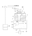
図11は、従来のインクジェットヘッド洗浄装置の一例を示す構成図である。このインクジェットヘッド洗浄装置500は、ヘッド洗浄容器51の下部に超音波洗浄機52を設け、このヘッド洗浄容器51の中に洗浄液53を溜めた構成である。周波数変換部(図示省略)は、超音波洗浄機52の周波数を変更可能とする。このインクジェットヘッド洗浄装置500では、インクジェットヘッド60をヘッド洗浄容器51に浸漬し、超音波洗浄機52によりその振動数を変更しながら、当該インクジェットヘッド60の洗浄を行う。
しかしながら、上記従来のインクジェットヘッド洗浄装置500によれば、超音波のみで汚れを除去する構成であるが、実際は超音波のみでは落とせない汚れがノズル面に残ってしまうという問題点があった。また、ノズル面の汚れはノズルの詰りやインク滴の飛行曲がりの原因となる。この発明の目的は、係る問題点を解決するためになされたものである。
本発明に係るプリンタヘッド洗浄装置は、プリンタヘッドのノズル面を浸漬する洗浄液を入れる洗浄槽と、前記洗浄槽の内部に設けられ且つ前記プリンタヘッドのノズル面に接触する多数の微細端部を有するブラシ部に洗浄液の汚れを分解するための洗浄用の周波数の超音波振動を付加する洗浄振動付加手段とを備えたことを特徴とする。
洗浄槽にプリンタヘッドのノズル面を浸漬した状態で、前記ブラシ部の微細端部(例えばブラシの毛先)をノズル面に接触させる。この状態で洗浄振動付加手段である圧電素子等により超音波振動を付加すると、超音波振動によりノズル面の汚れが分解除去されると共にノズル面に接触したブラシ部の微細端部が振動し、ノズル面のしつこい汚れを取り除く。また、ブラシ部を動かすと、前記微細端部がノズル面を掻き、当該ノズル面の汚れを除去する。これにより、超音波のみで落とし難い汚れを確実に除去できるようになる。なお、洗浄振動付加手段は、圧電素子やモータ等である。
また、前記ブラシ部は、前記多数の微細端部を保持する基部を有し、この基部に対して前記洗浄振動付加手段を設けても良い。
基部(回転軸など)に洗浄振動付加手段を設けることで基部に対して超音波を直接付加でき、ブラシ部の微細端部に振動が良く伝わる。これにより、ノズル面の汚れを効果的に除去できる。
更に、前記ブラシ部の全体を動かすと共に前記洗浄振動付加手段として機能する駆動手段を設けても良い。
更にブラシ部の全体を動かすことでノズル面の汚れを効果的に除去できる。また、駆動手段を洗浄振動付加手段として機能させることで、当該洗浄振動付加手段を別に設ける必要がなくなり全体構成が簡略化される。
本発明に係るインクジェット印刷装置は、上記プリンタヘッド洗浄装置と、プリンタヘッドのノズルに連通するインク室に面した振動部材に振動を与える振動付加手段に所定周波数の電圧を印加すると共に、通常モードでは、前記振動付加手段に電圧を印加することで前記ノズルからインクを吐出して印刷を行い、洗浄モードでは、印刷用の周波数と異なる、前記インク室内およびノズルの洗浄用の周波数の電圧を前記振動付加手段に印加する電圧印加手段と、を備えたことを特徴とする。
洗浄用の周波数は、ヘッド内の汚れを引き剥がすのに有効な周波数であり、前記振動付加手段に印加することでヘッド内に当該周波数の振動が伝わり、ヘッド内の汚れが除去される。なお、前記洗浄用の周波数の電圧は、印刷時に電圧を印加する時間よりも長い時間連続的に印加しても良い。これにより汚れをインク室の壁面から引き剥がし又は分解できる。ヘッド内の汚れの除去において超音波振動を生成するにあたり、印刷時に用いる振動付加手段を用いるので、別途振動付加手段を設ける必要がない。
本発明によれば、ブラシ部によりノズル面の超音波では落とし難い汚れを除去することができる。
(実施の形態1)
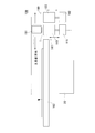
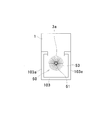
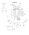
図1は、この発明の実施の形態1に係るインクジェットプリンタを示す構成図である。図2A, 図2B, 図3, 図4は、図1に示したインクジェットプリンタのキャッピングステーションを示す構成図である。図5は、図1に示したインクジェットプリンタのワイパーユニットを示す構成図である。図6は、このインクジェットプリンタのコントローラを示す構成図である。図7は、キャッピングステーションのキャップを示す平面図である。このインクジェットプリンタ100は、プリンタヘッド1と、プリンタヘッド1を保持すると共に主走査方向に移動するキャリッジ151と、メディアMを載せるプラテン又はテーブル152と、主走査方向のメディアMの印刷領域の外に設けたキャッピングステーション160と、キャッピングステーション160に隣接して設けたワイパーユニット161と、インクジェットプリンタの動作を制御するコントローラ20とを有する。
図1は、この発明の実施の形態1に係るインクジェットプリンタを示す構成図である。図2A, 図2B, 図3, 図4は、図1に示したインクジェットプリンタのキャッピングステーションを示す構成図である。図5は、図1に示したインクジェットプリンタのワイパーユニットを示す構成図である。図6は、このインクジェットプリンタのコントローラを示す構成図である。図7は、キャッピングステーションのキャップを示す平面図である。このインクジェットプリンタ100は、プリンタヘッド1と、プリンタヘッド1を保持すると共に主走査方向に移動するキャリッジ151と、メディアMを載せるプラテン又はテーブル152と、主走査方向のメディアMの印刷領域の外に設けたキャッピングステーション160と、キャッピングステーション160に隣接して設けたワイパーユニット161と、インクジェットプリンタの動作を制御するコントローラ20とを有する。
前記プリンタヘッド1は、図4に示すように、本体2と、ノズル面3aに吐出口を有するノズル3と、ノズル3に溝4を介して接続される導入口5と、ノズル3の上部に形成されるインク室6と、インク室6の上部に形成された当該インク室6に面して設けたダイアフラム膜7に積層形成した圧電素子8とを有する。圧電素子8には下電極8a及び上電極8bが積層されている。下電極8a及び上電極8bは、圧電素子8に電力供給する電源9に接続されている。なお、図4では、一つのノズル3を拡大して模式的に示したが当該ノズル3は、プリンタヘッド1のノズル面3aに多数形成される。前記電源9は、圧電素子8に駆動電圧を供給するドライバ回路12に接続されている。ドライバ回路12はコントローラ20により制御される。
前記キャッピングステーション160は、図2A, 図2B, 図4に示すように、洗浄液104を溜める洗浄槽となるキャップ103と、コントローラ20に接続され前記キャップ103を上下動させるアクチュエータ102とから構成される。前記キャップ103には、例えばチュービングポンプからなるポンプ11が接続されている。ポンプ11は、チューブを介して洗浄液104を貯留する洗浄液タンク105に接続されている。前記キャップ103は、通常、プリンタヘッド1の乾燥を防止するため当該プリンタヘッド1に被せるものである。
また、図2A, 図2B, 図3に示すように、キャッピングステーション160は、キャップ103内に回転ブラシ50を有する。回転ブラシ50は、中空の回転軸51がキャップ103の側壁103aに軸支されており且つその一端51aはモータ52に接続されている。当該回転ブラシ50は、基部である回転軸51の周方向に多数の毛53が設けられ、全体として円柱形状となる。毛53の毛先は尖って形成される。回転ブラシ50の毛53は、ポリプロピレン、ポリエチレンテレフタラート、ポリエステル、ナイロン、アラミド等からなる。また、回転ブラシ50は、プリンタヘッド1にキャップ103を被せた状態で当該回転ブラシ50の毛先がノズル3のノズル面3aに接触する位置関係とする。
回転軸51の一端51aは、モータ52の回転軸とキー溝で係合している。回転ブラシ50の毛53は、微細端部となるため、ノズル面3aに接触して動くことでノズル面3aの汚れを容易に取り除くことができる。なお、回転軸51は、キャップ103の軸受に回転自在に支持されている。前記モータ52は、コントローラ20に接続される。モータ52は、ステッピングモータから構成される。モータ52は、ドライバ回路54により駆動される。ドライバ回路54は、ブラシ駆動部31からの駆動信号により回転が制御される。
図2Bは、図2Aの点線で囲われた部分A,Bそれぞれの拡大図である。図2Bに示すように、回転軸51の内側略中央には、圧電素子150が設けられる。圧電素子150には、通電用の電線152が接続される。この電線152は、回転軸51の中を通り、当該回転軸51の他端51bまで配設される。回転軸51の他端51bには、円盤状の蓋153が設けられ、この蓋153の外面にリング状の電極154が形成される。また、当該他端51bにはカバー133が設けられている。カバー133の内側にはブラシ155が設けられ、その先端が前記電極154に接触する。このブラシ155は、ドライバ回路156に接続される。このドライバ回路156は、圧電素子150を駆動するものであり、前記コントローラ20に接続される。
また、キャップ103には、自動レベル調整器180が接続されている。この自動レベル調整器180は、キャップ103と接続され且つ内部に洗浄液104を入れる調整タンク181と、調整タンク181の上部に配置された供給タンク183とから構成される。供給タンク183の底部から下方に向けて管184が延出しており、この管184の先端は、調整タンク181の液面に浸されている。調整タンク181には、大気と連通する連通口182が設けられている。
この自動レベル調整器180は、キャップ103に洗浄液104を供給することで当該キャップ103の液面を一定に保つ。この自動レベル調整器180では、調整タンク181からの洗浄液104の供給によりその液面が下がると、供給タンク183の管184の下端が液面から出て、当該管184の先端から空気が入る。空気は、管184を通じて供給タンク183に入り、この供給タンク183の圧力が上昇し、液面が下がると共に管184から洗浄液が調整タンク181に供給される。これにより調整タンク181の液面が上昇し、管184の下端が液面下に浸され、当該先端からの空気の供給が遮断され、供給タンク183からの洗浄液104の供給が止まる。これを繰り返すことで調整タンク181の液面は管184の先端付近に保たれる。
ワイパーユニット161は、容器本体113と、容器本体113内に向けたワイパー装置114と、容器本体113を上下動させるアクチュエータ115とから構成される。前記ワイパー装置114は、ノズル面3aに沿って移動するスライダ116と、スライダ116の上部に設けた長尺帯状のゴム製のワイパー117と、ワイパー117に積層して設けたスポンジ層118とから構成される。スライダ116は、図示しないアクチュエータにより移動される。容器本体113の内部は、ノズル面3aをワイピングした際に出る汚れや増粘したインクが落ちて溜まる構造である。
前記コントローラ20は、洗浄モードにおいて圧電素子150に対して加える電圧やその周波数を設定する洗浄設定部21と、洗浄モードにおいて設定された周波数により圧電素子150を駆動する指令をドライバ回路156に出す駆動制御部22と、ポンプ11の駆動を制御するポンプ制御部23と、ワイパーユニット161を制御するワイピング制御部30と、回転ブラシ50の回転を制御するブラシ制御部31とを備えている。また、当該コントローラ20及びこれに含まれる洗浄設定部21、駆動制御部22、ポンプ制御部23、ワイピング制御部30等は、演算装置、メモリ等のハードウェア及びこれらの所定の機能を実現させるプログラムから構成される。
前記洗浄設定部21では、洗浄モードにおいて前記圧電素子150により発生させる振動の周波数を3段階に設定する。具体的には、圧電素子150により発生させる振動の周波数を、28kHz、45kHz、100kHzのそれぞれ±20%以内に設定する。ユーザは、洗浄設定部21によりこれらの周波数のいずれか又はその組合せを選択できる。また、当該周波数は、コントローラ20に接続した表示手段24に表示する洗浄ボタン25により変更可能である。例えば、30kHz、120kHz等に変更することもできる。前記表示手段24には、タッチ式の液晶パネル等を用いる。前記洗浄ボタン25としては、「強力洗浄」、「通常洗浄」、「微細洗浄」の3種類が表示される。「強力洗浄」は、低周波数の28kHzで行う。「通常洗浄」は、45kHz、「微細洗浄」は100kHzに割り付けられる。なお、洗浄ボタン25は機械的なボタンとしても良い。
また、上記各周波数を重畳した電圧を印加するようにしても良い。この場合、圧電素子150に重畳する周波数は、前記洗浄設定部21により設定する。更に、周波数の重畳は断片的に行うこともできる。例えば、「微細洗浄」として100kHzの周波数の電圧を印加しつつ断片的に「強力洗浄」の28kHzの周波数の電圧を印加することもできる。前記ポンプ11は、モータ13により駆動される。前記洗浄設定部21では、洗浄のタイミングや洗浄時間を設定できる。例えば、隔日の所定時刻に定期的に行われるように設定できる。また、インクジェットプリンタ100を起動した際に自動的に行うように設定できる。
また、周波数は連続的に変化させるように設定できるようにしても良い。例えば、1kHz~100kHzの間で1kHzおきに変化させることもできる。また、リニアに変化させても良いし、所定のカーブ特性により変化させても良い。
洗浄の強度の組み合わせも自由に設定できる。当該組合せは、組合ボタン26から入る画面(図示省略)により設定できる。例えば、最初に前記「強力洗浄」を行い、所定時間経過後、「通常洗浄」を行い、更に所定時間経過後、「微細洗浄」を行う。「強力洗浄」は、一度だけ行い、その後は「通常洗浄」及び「微細洗浄」を交互に行う。これらの組み合わせは前記洗浄設定部21により、順番、時間等を入力することでコントローラ20に記憶され、コントローラ20は当該設定に従って圧電素子150を駆動制御する。
キャップ103内の洗浄液の排出は、排出ボタン27によりポンプ11の駆動を開始することで行う。
次に、このインクジェットプリンタ100の動作について説明する。図8は、このインクジェットプリンタの動作を示すフローチャートである。なお、下記手順は、所定のプログラムにより実行されるものとする。
[洗浄内容の設定]
このインクジェットプリンタ100では、ヘッドの洗浄を行うに当たり、前記洗浄設定部21により洗浄に用いる周波数を設定する(ステップS1)。例えば、「強力洗浄」を行うため、表示手段24に表示されている「強力洗浄」の洗浄ボタン25を押す。
このインクジェットプリンタ100では、ヘッドの洗浄を行うに当たり、前記洗浄設定部21により洗浄に用いる周波数を設定する(ステップS1)。例えば、「強力洗浄」を行うため、表示手段24に表示されている「強力洗浄」の洗浄ボタン25を押す。
続いて、ユーザは洗浄設定部21により洗浄時間を設定する(ステップS2)。洗浄時間は、前記表示手段24により表示される。また、洗浄時間は秒単位で設定可能である。なお、洗浄時間を洗浄レベル毎にデフォルト設定しておくことで当該洗浄時間の設定プロセスを省略できる。
次に、選択した洗浄レベル(上記では「強力洗浄」を選択)とは別の周波数による洗浄レベルを組み合わせる場合(ステップS3)、表示手段24に表示されている組合せボタン26を押す(ステップS4)。これにより、組合せ画面(図示省略)に移行し、当該組合せ画面に表示されている洗浄ボタンから、例えば「微細洗浄」を選択する。これにより、「強力洗浄」の後に「微細洗浄」が行われるように設定される。これらはユーザにより任意に選択して組み合わせることができる。また、後述するが、洗浄ボタン25と共に排出ボタン27を選択して組み合わせることもできる。
次に、ユーザは洗浄設定部21により洗浄タイミングの設定を行う(ステップS5)。洗浄するタイミングとしては、インクジェットプリンタ100の運転開始時、運転休止中等である。これらのタイミングは、表示手段24により洗浄タイミングボタン28で表示される。例えば、「運転休止中」のボタンを押すと、コントローラ20は洗浄開始時間の入力画面(図示省略)に移行する。ユーザは、休止中の何時に洗浄動作を行うかを入力して設定する。例えば、午前0時に洗浄動作を行う旨の設定をする。また、「運転開始時」のボタンを押すと、次回電源9を入れた際に自動的に洗浄動作を行うことになる。
[洗浄の実行]
実際の洗浄においては、まず、前記キャリッジ151をワイパーユニット161の上方に移動し、アクチュエータ115を駆動してワイパーユニット161の容器本体113をプリンタヘッド1に対して装着する(ステップS6)。この状態で、スライダ116を移動させ先端のワイパー117によりノズル面3aを拭う。ノズル面3aに付着しているインクや汚れは、ワイパー117により拭われスポンジ層118に吸着される。
実際の洗浄においては、まず、前記キャリッジ151をワイパーユニット161の上方に移動し、アクチュエータ115を駆動してワイパーユニット161の容器本体113をプリンタヘッド1に対して装着する(ステップS6)。この状態で、スライダ116を移動させ先端のワイパー117によりノズル面3aを拭う。ノズル面3aに付着しているインクや汚れは、ワイパー117により拭われスポンジ層118に吸着される。
次に、前記ポンプ制御部23により前記ポンプ11を駆動して、キャッピングステーション160のキャップ103内に洗浄液104を導入する。そして、プリンタヘッド1をキャップ103の上方に移動し、アクチュエータ102によりキャップ103を上昇させ、前記プリンタヘッド1のノズル面3aに被せる(ステップS7)。
この状態でプリンタヘッド1のノズル面3aは、図2A, 図2B, 図4に示すように、キャップ103内の洗浄液104に浸漬される。そして、前記圧電素子150を上記設定した周波数により超音波振動させる(ステップS8)。この超音波振動により微細な泡が発生し、ノズル面3aに付着している高粘度のインク等の汚れがキャビテーションや加速度エネルギーの作用により除去される。また、回転ブラシ50の毛53に対して超音波が作用してこれを振動させる。振動した毛53は、ノズル面3aに接触してその表面の汚れを機械的に除去する。
更に、圧電素子150からの高周波振動は、ノズル穴の径よりも波長が短いため、ノズル内に侵入して当該ノズル3の内壁の汚れを分解する。また、回転ブラシ50の毛53が振動することで発生する超音波振動も当該毛53がノズル面3a近くにあるため、ノズル3内に侵入しやすい。
また、この超音波の付加と共にモータ52を駆動して回転ブラシ50を回転させる。回転ブラシ50の毛先は尖っており回転動作によりその先端がノズル面3aを引っ掻くようになるので、ノズル面3aの汚れが機械的に引き剥がされて除去される。回転ブラシ50の回転数は、例えば0.5rpmから10rpmである。このようにして分解或いは除去された汚れは洗浄液中に拡散する。
洗浄後、前記ポンプ11によりキャップ103内の洗浄液を吸引し、また前記ノズル3を介してインク室6内のインク及び洗浄液を排出する(ステップS9)。これにより分解した汚れを含んだ洗浄液は排出され、インク室6には新しいインクが導入される。
インクの排出後、アクチュエータ102を駆動してキャップ103を下げ、プリンタヘッド1からキャップ103を取り外す(ステップS10)。
次に、プリンタヘッド1を移動して再びワイパーユニット161上に位置させ、アクチュエータ115を駆動してプリンタヘッド1のノズル面3aにワイパー117を押し当て、スライダ116を移動させてノズル面3aのワイピングを行う(ステップS11)。
次に、ワイピングの際にノズル3内に別色のインクが押し込まれることがあるので、圧電素子8を駆動してフラッシングを行い(ステップS12)、ノズル3内に入り込んだ別色のインクを吐出する。このフラッシング動作は、ワイパーユニット161にプリンタヘッド1を入れた状態で行う。フラッシングで吐出されたインクは、ワイパーユニット161の容器本体113に落ちて溜まる。これにより、洗浄モードにおけるプリンタヘッド1の洗浄が完了し、その後は自動的に通常の印刷モードに戻る。
以上、この発明のインクジェットプリンタ100によれば、モータ52による超音波振動の印加と回転ブラシ50の接触によりノズル面3aの汚れを確実に除去できる。なお、上記回転ブラシ50はノズル面3aに接触する微細端部を多数有するものであれば良く、例えば、不織布やたわし状の繊維を前記回転軸51に取り付けた構成でも良い(図示省略)。
(実施の形態2)
また、洗浄モードにおいて、圧電素子150及び回転ブラシ50による洗浄と共に、前記プリンタヘッド1に設けた印刷用の圧電素子8を洗浄に併用することもできる。電源9及びコントローラ20は、洗浄用の周波数の電圧を圧電素子8に印加する電圧印加手段を形成する。洗浄設定部21は、圧電素子8に対して所定の洗浄周波数を印加する。例えば、圧電素子8に加える電圧の周波数を、28kHzの「強力洗浄」、45kHzの「通常洗浄」、100kHzの「微細洗浄」に設定する。なお、これらの周波数は、インクの種類やプリンタヘッド1の仕様等により異なる周波数を選定できる。また、ユーザは、洗浄設定部21によりこれらの周波数の電圧のいずれか又はその組合せを選択できる。また、当該周波数は、コントローラ20に接続した表示手段24に表示する洗浄ボタン25により変更可能である。
また、洗浄モードにおいて、圧電素子150及び回転ブラシ50による洗浄と共に、前記プリンタヘッド1に設けた印刷用の圧電素子8を洗浄に併用することもできる。電源9及びコントローラ20は、洗浄用の周波数の電圧を圧電素子8に印加する電圧印加手段を形成する。洗浄設定部21は、圧電素子8に対して所定の洗浄周波数を印加する。例えば、圧電素子8に加える電圧の周波数を、28kHzの「強力洗浄」、45kHzの「通常洗浄」、100kHzの「微細洗浄」に設定する。なお、これらの周波数は、インクの種類やプリンタヘッド1の仕様等により異なる周波数を選定できる。また、ユーザは、洗浄設定部21によりこれらの周波数の電圧のいずれか又はその組合せを選択できる。また、当該周波数は、コントローラ20に接続した表示手段24に表示する洗浄ボタン25により変更可能である。
洗浄設定部21では、電圧を制御して圧電素子8によるダイアフラム膜7の振幅を調整する。印刷を行う通常モードでは、コントローラ20は、ノズル3からインクを吐出するために必要な周波数や振幅が得られる電圧を前記圧電素子8に印加する。
洗浄時の圧電素子8の振動により洗浄液104が次第にインク室6の中に導入される。なお、インク室6内のインクを全て洗浄液に置き換える必要はない。インク室6ではインクに所定の超音波振動が伝わるので、インク室6の壁面にこびりついた汚れが引き剥がされ、分解される。インク室6に導入された洗浄液104は、分解した汚れを包みこむことで壁面に再付着するのを防止する。また、ノズル3内も前記洗浄液104の動作により洗浄される。
洗浄後、前記ポンプ11によりキャップ103内の洗浄液を吸引する際、ノズル3を介してインク室6内のインクが排出される。これにより分解した汚れを含んだインクはそのまま排出され、当該排出による圧力低下により新しいインクがインク室6内に導入される。また、洗浄モードにおける振動によりインク内でキャビテーションが生じ、これに伴い気泡が生じるが、インクを排出する際に気泡を含んだインクもそのまま排出されるので、当該気泡に起因した空打ちが防止される。
このようにすれば、インク室6に面して設けたダイアフラム膜7に設けた圧電素子8により洗浄するので、インク室6を直接洗浄できる。更に、洗浄液104によりインク室6内を洗浄するので高いクリーニング効果が得られる。
また、上記ステップS9では、洗浄後にキャップ103内をポンプ11により吸引して負圧にし、前記ノズル3を介してインク室6から汚れたインクを吸引排出するようにしたが、この吸引をすることなく、前記インク室6にインクの供給を行うことで積極的にインクを排出するようにしても良い。そして、キャップ103を下げてプリンタヘッド1から前記キャップ103を外し(ステップS10)、上記同様、ワイピング(ステップS11)、フラッシング(ステップS12)を行う。これらのステップは、コントローラ20の洗浄設定部21により設定され、この手順に従ってポンプ11やワイパーユニット161が制御される。
また、上記コントローラ20の洗浄設定部21は、キャビテーションの小さな気泡に高周波を減衰する効果があるため、微小な泡が増加した際はインクの排出を行ってから次の周波数による洗浄を行うようにしても良い。例えば、図9Aに示すように、「強力洗浄」を28kHzで行い、微小な気泡が生じたインクをインク室6から排出して新しいインクをインク室6に導入し、この新しいインクに対して100kHzの周波数で「微小洗浄」を行う。このように、微小気泡を含むインクを排出してから別の周波数による洗浄を行うと洗浄効果がより向上する。特に、高周波の洗浄を行う前にインクの排出及び導入を行うと、洗浄の効果が向上する。
また、図9Bに示すように、「強力洗浄」、「通常洗浄」、「微細洗浄」の間にそれぞれ排出動作を設定することもできる。なお、排出動作は、前記ポンプ11を駆動してキャップ103を通じて行う。
一方、図9Cに示すように、高い周波数(「微細洗浄」である100kHz)による洗浄を先に行い、気泡による影響が低い周波数(例えば周波数が他の洗浄時より低い「強力洗浄」である28kHz)により洗浄する順番であれば、インクの排出をすることなく、かつ、微小な気泡による減衰を抑制しつつ、洗浄が可能である。また、図9Dに示すように、「通常洗浄」、「強力洗浄」の順番で行うこともできる。
(実施の形態3)
図10Aおよび図10Bは、この発明の実施の形態3に係るインクジェットプリンタを示す構成図である。このインクジェットプリンタ250は、上記実施の形態1に係るインクジェットプリンタ100と略同様の構成であるが、圧電素子170をブラシ172の駆動軸173の端部に設け、ブラシ172の基台174の穴175に前記駆動軸173を通した構成である。その他の構成は、実施の形態1と同様であるからその説明を省略する。
図10Aおよび図10Bは、この発明の実施の形態3に係るインクジェットプリンタを示す構成図である。このインクジェットプリンタ250は、上記実施の形態1に係るインクジェットプリンタ100と略同様の構成であるが、圧電素子170をブラシ172の駆動軸173の端部に設け、ブラシ172の基台174の穴175に前記駆動軸173を通した構成である。その他の構成は、実施の形態1と同様であるからその説明を省略する。
圧電素子170はカバー171によりキャップ103に固定される。また圧電素子170には、金属製の前記駆動軸173が接合される。駆動軸173は、断面が矩形であり且つ前記キャップ103内の長手方向に配置される。図10Aに示すように、基台174の穴175は駆動軸173を挿通できる矩形断面である。これによりブラシ172が駆動軸173に沿って回転することなくスライド可能になる。圧電素子171は、駆動軸173に対して所定形状の波を与え、駆動軸173に差し込んだ基台174を往復運動させる。
圧電素子170には、駆動軸173が一方向にゆっくり伸び逆方向に急速に縮む動作をする電圧の信号波形を与え、基台174を往復運動させる。図10Bに示すように、伸縮変位の山形波形の図中左側を緩やかにすることで基台174は図中右方向に進み、図中右側を緩やかにすることで基台174は図中左方向に進む。これらの動作は、コントローラ20のブラシ駆動部31により行われる。また、前記駆動軸173に与える周波数は、上記実施の形態1に示した洗浄用の周波数とする。これにより超音波振動が洗浄液中に伝わると共に、ブラシ172の毛先を振動させる。
ブラシ172は、駆動軸173に与えた所定の波により往復運動するので、ブラシ172の毛先でノズル面3aが掻かれノズル面3aに付着している汚れが機械的に除去される。また、ブラシ172から超音波振動が洗浄液に伝わり、ノズル3内に超音波が侵入してノズル3内の汚れを分解し除去する。これにより、洗浄液から伝播した超音波がノズル3に侵入して上記同様にノズル3内及びインク室6内の汚れを分解して洗浄する。
この構成によれば、ブラシ172を往復運動させる駆動手段と、洗浄剤に超音波振動を付加する洗浄振動付加手段とを一つの上記構成により実現できるので、モータと圧電素子とを別に設ける必要がなく、構造的に簡略化できる。
(その他の実施の形態)
図示しないが、実施の形態1においてモータ52として、超音波モータを用いても良い。このとき、圧電素子150は不要である。回転時の高周波の超音波をステータから機械的に取り出して、前記回転軸51と連結しても良い。例えばステータの圧電素子を回転軸51の端部に摺動可能に押圧連結し、超音波モータの回転軸と前記回転軸51との間を減速機で接続しても良い。また、モータ52として高分解能のステップモータを用い、ステップモータに振動が生じるような制御を行う。このとき、圧電素子150は不要である。
図示しないが、実施の形態1においてモータ52として、超音波モータを用いても良い。このとき、圧電素子150は不要である。回転時の高周波の超音波をステータから機械的に取り出して、前記回転軸51と連結しても良い。例えばステータの圧電素子を回転軸51の端部に摺動可能に押圧連結し、超音波モータの回転軸と前記回転軸51との間を減速機で接続しても良い。また、モータ52として高分解能のステップモータを用い、ステップモータに振動が生じるような制御を行う。このとき、圧電素子150は不要である。
100 インクジェットプリンタ
160 キャッピングステーション
161 ワイパーユニット
1 プリンタヘッド
2 本体
3 ノズル
6 インク室
7 ダイアフラム膜
8 圧電素子
11 ポンプ
20 コントローラ
21 洗浄設定部
22 駆動制御部
23 ポンプ制御部
24 表示手段
150 圧電素子
160 キャッピングステーション
161 ワイパーユニット
1 プリンタヘッド
2 本体
3 ノズル
6 インク室
7 ダイアフラム膜
8 圧電素子
11 ポンプ
20 コントローラ
21 洗浄設定部
22 駆動制御部
23 ポンプ制御部
24 表示手段
150 圧電素子
Claims (4)
- プリンタヘッドのノズル面を浸漬する洗浄液を入れる洗浄槽と、
前記洗浄槽の内部に設けられ且つ前記プリンタヘッドのノズル面に接触する多数の微細端部を有するブラシ部に洗浄液の汚れを分解するための洗浄用の周波数の超音波振動を付加する洗浄振動付加手段と、
を備えたことを特徴とするプリンタヘッド洗浄装置。 - 前記ブラシ部は、前記多数の微細端部を保持する基部を有し、この基部に対して前記洗浄振動付加手段を設けたことを特徴とする請求項1に記載のプリンタヘッド洗浄装置。
- 更に、前記ブラシ部の全体を動かすと共に前記洗浄振動付加手段として機能する駆動手段を有することを特徴とする請求項1又は2に記載のプリンタヘッド洗浄装置。
- 請求項1~3のいずれか一つに記載のプリンタヘッド洗浄装置と、
プリンタヘッドのノズルに連通するインク室に面した振動部材に振動を与える振動付加手段に所定周波数の電圧を印加すると共に、通常モードでは、前記振動付加手段に電圧を印加することで前記ノズルからインクを吐出して印刷を行い、洗浄モードでは、印刷用の周波数と異なる、前記インク室内およびノズルの洗浄用の周波数の電圧を前記振動付加手段に印加する電圧印加手段と、
を備えたことを特徴とするインクジェット印刷装置。
Priority Applications (1)
| Application Number | Priority Date | Filing Date | Title |
|---|---|---|---|
| US14/646,386 US9399346B2 (en) | 2012-11-22 | 2013-11-22 | Printer head cleaning device and inkjet printing device |
Applications Claiming Priority (2)
| Application Number | Priority Date | Filing Date | Title |
|---|---|---|---|
| JP2012-256897 | 2012-11-22 | ||
| JP2012256897A JP6099946B2 (ja) | 2012-11-22 | 2012-11-22 | プリンタヘッド洗浄装置及びインクジェット印刷装置 |
Publications (1)
| Publication Number | Publication Date |
|---|---|
| WO2014081019A1 true WO2014081019A1 (ja) | 2014-05-30 |
Family
ID=50776195
Family Applications (1)
| Application Number | Title | Priority Date | Filing Date |
|---|---|---|---|
| PCT/JP2013/081555 Ceased WO2014081019A1 (ja) | 2012-11-22 | 2013-11-22 | プリンタヘッド洗浄装置及びインクジェット印刷装置 |
Country Status (3)
| Country | Link |
|---|---|
| US (1) | US9399346B2 (ja) |
| JP (1) | JP6099946B2 (ja) |
| WO (1) | WO2014081019A1 (ja) |
Cited By (2)
| Publication number | Priority date | Publication date | Assignee | Title |
|---|---|---|---|---|
| JPWO2016002896A1 (ja) * | 2014-07-03 | 2017-04-27 | 株式会社ミマキエンジニアリング | ヘッド洗浄装置及びインクジェットプリンタ |
| CN115071277A (zh) * | 2021-03-16 | 2022-09-20 | 海德堡印刷机械股份公司 | 用于清洁用于喷墨印刷的印刷头的方法 |
Families Citing this family (13)
| Publication number | Priority date | Publication date | Assignee | Title |
|---|---|---|---|---|
| JP2016104520A (ja) * | 2014-12-01 | 2016-06-09 | セイコーエプソン株式会社 | 液体噴射装置、超音波洗浄装置、及び、超音波洗浄方法 |
| JP6500581B2 (ja) * | 2015-04-30 | 2019-04-17 | 富士ゼロックス株式会社 | 洗浄装置及び液滴吐出装置 |
| CN107053850A (zh) * | 2015-09-28 | 2017-08-18 | 罗兰Dg有限公司 | 喷墨打印机 |
| JP2017074535A (ja) * | 2015-10-13 | 2017-04-20 | アルファーデザイン株式会社 | 液体吐出装置 |
| US10507652B2 (en) * | 2018-03-14 | 2019-12-17 | The Regents Of The University Of Michigan | Rapidly-wetted pin-style electro-hydrodynamic jet print head |
| US11065817B2 (en) | 2018-08-14 | 2021-07-20 | Massivit 3D Printing Technologies Ltd. | Extrusion orifice cleaning |
| KR102785412B1 (ko) * | 2019-06-13 | 2025-03-27 | 삼성디스플레이 주식회사 | 잉크젯 장치 및 잉크젯 장치의 프린팅 방법 |
| US10940689B1 (en) | 2019-09-05 | 2021-03-09 | The Regents Of The University Of Michigan | Multi-nozzle print head assembly with ink retraction mechanism |
| JP7366725B2 (ja) * | 2019-12-12 | 2023-10-23 | 株式会社キーエンス | インクジェット記録システム |
| KR102734052B1 (ko) * | 2021-04-12 | 2024-11-26 | 세메스 주식회사 | 잉크젯 헤드 세정 장치 및 이를 포함하는 잉크젯 프린팅 설비 |
| CN114261209B (zh) * | 2021-12-23 | 2023-04-07 | 永城盛大印刷科技股份有限公司 | 双色高速数码轮转超声波温湿度喷头系统 |
| JP2023181803A (ja) * | 2022-06-13 | 2023-12-25 | 株式会社リコー | 液体吐出ヘッドのメンテナンス装置 |
| JP2024081083A (ja) * | 2022-12-05 | 2024-06-17 | 株式会社リコー | 払拭装置、ヘッドメンテナンス装置、液体を吐出する装置 |
Citations (3)
| Publication number | Priority date | Publication date | Assignee | Title |
|---|---|---|---|---|
| JP2004034702A (ja) * | 2002-06-28 | 2004-02-05 | Agfa Gevaert Nv | ノズルプレートの清掃方法 |
| JP2008073638A (ja) * | 2006-09-22 | 2008-04-03 | Ntn Corp | 塗布針洗浄方法、塗布針洗浄装置およびこれを備えたパターン修正装置 |
| JP2012040502A (ja) * | 2010-08-19 | 2012-03-01 | Seiko Epson Corp | 液滴吐出ヘッドの洗浄方法 |
Family Cites Families (2)
| Publication number | Priority date | Publication date | Assignee | Title |
|---|---|---|---|---|
| JP2007090584A (ja) | 2005-09-28 | 2007-04-12 | Mutoh Ind Ltd | インクジェットヘッド洗浄装置 |
| JP2012076261A (ja) * | 2010-09-30 | 2012-04-19 | Riso Kagaku Corp | インクジェット印刷装置 |
-
2012
- 2012-11-22 JP JP2012256897A patent/JP6099946B2/ja active Active
-
2013
- 2013-11-22 WO PCT/JP2013/081555 patent/WO2014081019A1/ja not_active Ceased
- 2013-11-22 US US14/646,386 patent/US9399346B2/en active Active
Patent Citations (3)
| Publication number | Priority date | Publication date | Assignee | Title |
|---|---|---|---|---|
| JP2004034702A (ja) * | 2002-06-28 | 2004-02-05 | Agfa Gevaert Nv | ノズルプレートの清掃方法 |
| JP2008073638A (ja) * | 2006-09-22 | 2008-04-03 | Ntn Corp | 塗布針洗浄方法、塗布針洗浄装置およびこれを備えたパターン修正装置 |
| JP2012040502A (ja) * | 2010-08-19 | 2012-03-01 | Seiko Epson Corp | 液滴吐出ヘッドの洗浄方法 |
Cited By (3)
| Publication number | Priority date | Publication date | Assignee | Title |
|---|---|---|---|---|
| JPWO2016002896A1 (ja) * | 2014-07-03 | 2017-04-27 | 株式会社ミマキエンジニアリング | ヘッド洗浄装置及びインクジェットプリンタ |
| CN115071277A (zh) * | 2021-03-16 | 2022-09-20 | 海德堡印刷机械股份公司 | 用于清洁用于喷墨印刷的印刷头的方法 |
| CN115071277B (zh) * | 2021-03-16 | 2023-12-26 | 海德堡印刷机械股份公司 | 用于清洁用于喷墨印刷的印刷头的方法 |
Also Published As
| Publication number | Publication date |
|---|---|
| JP2014104594A (ja) | 2014-06-09 |
| US20150336388A1 (en) | 2015-11-26 |
| US9399346B2 (en) | 2016-07-26 |
| JP6099946B2 (ja) | 2017-03-22 |
Similar Documents
| Publication | Publication Date | Title |
|---|---|---|
| JP6099946B2 (ja) | プリンタヘッド洗浄装置及びインクジェット印刷装置 | |
| JP3961206B2 (ja) | ノズルクリーナ方法とノズルクリーナ及びインクジェット記録装置 | |
| JP6225485B2 (ja) | 液体噴射装置、及び、その制御方法 | |
| CN106079901B (zh) | 清洁装置和液滴喷射装置 | |
| WO2015146951A1 (ja) | ヘッド洗浄装置、インクジェットプリンターおよびヘッド洗浄方法 | |
| JP6384157B2 (ja) | 液体噴射装置、及び、その制御方法 | |
| WO2013150977A1 (ja) | 洗浄方法、洗浄装置及びインクジェット記録装置 | |
| JP2018187792A (ja) | 液体吐出装置および液体吐出装置の動作方法 | |
| JP2006347000A (ja) | 洗浄機能を備える液滴吐出装置及び液滴吐出装置の洗浄方法 | |
| KR20100083033A (ko) | 와이퍼 클리닝 기능이 개선된 잉크젯 프린터 | |
| KR20090128243A (ko) | 노즐 습윤장치 및 이를 구비한 잉크젯 화상형성장치 | |
| KR101254275B1 (ko) | 폴리이미드막 도포 장치 및 방법 | |
| JP6245750B2 (ja) | グラビア印刷機 | |
| JP2010247360A (ja) | ヘッドクリーニング装置、流体噴射装置、およびヘッドクリーニング方法 | |
| JP2009149041A (ja) | インクジェットヘッドの洗浄装置及びインクジェット記録装置 | |
| WO2014073651A1 (ja) | インクジェット印刷装置及びプリンタヘッド洗浄プログラム | |
| JP2007090584A (ja) | インクジェットヘッド洗浄装置 | |
| JP7031254B2 (ja) | 液体吐出装置の駆動方法 | |
| JP6041605B2 (ja) | インクジェット記録装置及びインクジェットヘッドの清掃方法 | |
| JP4246110B2 (ja) | 印刷用マスクのクリーニング装置 | |
| JP2018065256A (ja) | 液体吐出装置、洗浄装置および洗浄方法 | |
| JPH05175184A (ja) | ウエハの洗浄方法 | |
| JP2013121712A (ja) | 液滴吐出装置及び清掃方法 | |
| JPH05275408A (ja) | 平面状基板の洗浄装置 | |
| JP2019025767A (ja) | 液体噴射装置及びその制御方法 |
Legal Events
| Date | Code | Title | Description |
|---|---|---|---|
| 121 | Ep: the epo has been informed by wipo that ep was designated in this application |
Ref document number: 13856999 Country of ref document: EP Kind code of ref document: A1 |
|
| WWE | Wipo information: entry into national phase |
Ref document number: 14646386 Country of ref document: US |
|
| NENP | Non-entry into the national phase |
Ref country code: DE |
|
| 122 | Ep: pct application non-entry in european phase |
Ref document number: 13856999 Country of ref document: EP Kind code of ref document: A1 |