WO2014077382A1 - 拡管プラグ及び金属管の拡管方法 - Google Patents
拡管プラグ及び金属管の拡管方法 Download PDFInfo
- Publication number
- WO2014077382A1 WO2014077382A1 PCT/JP2013/081009 JP2013081009W WO2014077382A1 WO 2014077382 A1 WO2014077382 A1 WO 2014077382A1 JP 2013081009 W JP2013081009 W JP 2013081009W WO 2014077382 A1 WO2014077382 A1 WO 2014077382A1
- Authority
- WO
- WIPO (PCT)
- Prior art keywords
- tube
- expansion plug
- tube expansion
- dlc film
- metal
- Prior art date
- Legal status (The legal status is an assumption and is not a legal conclusion. Google has not performed a legal analysis and makes no representation as to the accuracy of the status listed.)
- Ceased
Links
Images


Classifications
-
- B—PERFORMING OPERATIONS; TRANSPORTING
- B21—MECHANICAL METAL-WORKING WITHOUT ESSENTIALLY REMOVING MATERIAL; PUNCHING METAL
- B21D—WORKING OR PROCESSING OF SHEET METAL OR METAL TUBES, RODS OR PROFILES WITHOUT ESSENTIALLY REMOVING MATERIAL; PUNCHING METAL
- B21D51/00—Making hollow objects
- B21D51/16—Making hollow objects characterised by the use of the objects
- B21D51/38—Making inlet or outlet arrangements of cans, tins, baths, bottles, or other vessels; Making can ends; Making closures
- B21D51/44—Making closures, e.g. caps
- B21D51/46—Placing sealings or sealing material
-
- B—PERFORMING OPERATIONS; TRANSPORTING
- B21—MECHANICAL METAL-WORKING WITHOUT ESSENTIALLY REMOVING MATERIAL; PUNCHING METAL
- B21D—WORKING OR PROCESSING OF SHEET METAL OR METAL TUBES, RODS OR PROFILES WITHOUT ESSENTIALLY REMOVING MATERIAL; PUNCHING METAL
- B21D51/00—Making hollow objects
- B21D51/16—Making hollow objects characterised by the use of the objects
- B21D51/38—Making inlet or outlet arrangements of cans, tins, baths, bottles, or other vessels; Making can ends; Making closures
- B21D51/44—Making closures, e.g. caps
- B21D51/48—Making crown caps
-
- C—CHEMISTRY; METALLURGY
- C10—PETROLEUM, GAS OR COKE INDUSTRIES; TECHNICAL GASES CONTAINING CARBON MONOXIDE; FUELS; LUBRICANTS; PEAT
- C10M—LUBRICATING COMPOSITIONS; USE OF CHEMICAL SUBSTANCES EITHER ALONE OR AS LUBRICATING INGREDIENTS IN A LUBRICATING COMPOSITION
- C10M103/00—Lubricating compositions characterised by the base-material being an inorganic material
- C10M103/02—Carbon; Graphite
-
- C—CHEMISTRY; METALLURGY
- C10—PETROLEUM, GAS OR COKE INDUSTRIES; TECHNICAL GASES CONTAINING CARBON MONOXIDE; FUELS; LUBRICANTS; PEAT
- C10M—LUBRICATING COMPOSITIONS; USE OF CHEMICAL SUBSTANCES EITHER ALONE OR AS LUBRICATING INGREDIENTS IN A LUBRICATING COMPOSITION
- C10M2201/00—Inorganic compounds or elements as ingredients in lubricant compositions
- C10M2201/04—Elements
- C10M2201/041—Carbon; Graphite; Carbon black
- C10M2201/0413—Carbon; Graphite; Carbon black used as base material
-
- C—CHEMISTRY; METALLURGY
- C10—PETROLEUM, GAS OR COKE INDUSTRIES; TECHNICAL GASES CONTAINING CARBON MONOXIDE; FUELS; LUBRICANTS; PEAT
- C10N—INDEXING SCHEME ASSOCIATED WITH SUBCLASS C10M RELATING TO LUBRICATING COMPOSITIONS
- C10N2040/00—Specified use or application for which the lubricating composition is intended
- C10N2040/20—Metal working
- C10N2040/241—Manufacturing joint-less pipes
-
- C—CHEMISTRY; METALLURGY
- C10—PETROLEUM, GAS OR COKE INDUSTRIES; TECHNICAL GASES CONTAINING CARBON MONOXIDE; FUELS; LUBRICANTS; PEAT
- C10N—INDEXING SCHEME ASSOCIATED WITH SUBCLASS C10M RELATING TO LUBRICATING COMPOSITIONS
- C10N2050/00—Form in which the lubricant is applied to the material being lubricated
- C10N2050/08—Solids
-
- C—CHEMISTRY; METALLURGY
- C10—PETROLEUM, GAS OR COKE INDUSTRIES; TECHNICAL GASES CONTAINING CARBON MONOXIDE; FUELS; LUBRICANTS; PEAT
- C10N—INDEXING SCHEME ASSOCIATED WITH SUBCLASS C10M RELATING TO LUBRICATING COMPOSITIONS
- C10N2050/00—Form in which the lubricant is applied to the material being lubricated
- C10N2050/14—Composite materials or sliding materials in which lubricants are integrally molded
Definitions
- the present invention relates to a tube expansion plug used for expanding a metal tube and a tube expansion method using the same.
- Refrigerators and air conditioners for air conditioning generally use cross fin tube type heat exchangers.
- This heat exchanger is composed of an air-side fin material and a refrigerant pipe made of a refrigerant-side metal pipe.
- Such a cross fin tube type heat exchanger is generally manufactured as follows. First, a fin material having a predetermined collar portion is laminated. Next, a metal tube is inserted into the cylindrical collar portion. Thereafter, a tube expansion process is performed in which a tube expansion plug having an outer diameter larger than the inner diameter of the metal tube is forcibly inserted into the metal tube to expand the outer diameter of the metal tube. Thereby, the metal tube is fixed to the fin material. As a result, a cross fin tube type heat exchanger is obtained. As the metal tube, a copper tube or an aluminum tube is used.
- a high-viscosity lubricating oil was used to reduce the amount of lubricating oil while reducing the friction between the pipe expanding jig and the metal pipe.
- the lubricating oil adhering to the inside of the metal pipe after the pipe expansion processing is volatilized and removed.
- lubricating oils with high viscosity are generally poor in volatility. For this reason, the lubricating oil is not sufficiently removed even in the removing step and may remain in the metal tube. As a result, the reliability of the heat exchanger may be reduced.
- the amount of lubricating oil is reduced for cost reduction, there is a possibility that the pipe expanding jig and the metal pipe are seized. As a result, there is a possibility that the tube expansion process cannot be performed.
- a technique for reducing the amount of lubricating oil used for tube expansion processing has been developed by using a tube expansion jig formed with a diamond-like carbon (hereinafter referred to as “DLC” as appropriate) film (see Patent Document 1).
- Other techniques using the DLC film include a technique for forming a DLC film on the surface of the sliding member (see Patent Document 2), and a hard carbon coating such as a DLC film on the contact surface with the work surface.
- a technique related to the provided rolling tool has been developed (see Patent Document 3).
- JP 2008-093713 A JP 2012-007199 A Japanese Patent Laying-Open No. 2005-066700
- the present invention has been made in view of such a background, and even with a small amount of lubricating oil, the tube expansion load can be sufficiently and reliably reduced, and adhesion of metal wear powder can be sufficiently and reliably suppressed. Furthermore, the present invention intends to provide a tube expansion plug having excellent durability and a method of processing a metal tube using the tube expansion plug.
- One aspect of the present invention is a tube expansion plug used for forcibly inserting a tube expansion plug having an outer diameter larger than the inner diameter of the metal tube into the metal tube to expand the outer diameter of the metal tube
- the tube expansion plug has a plug body, a base layer coated on the surface of the plug body, and a diamond-like carbon film coated on the base layer,
- the underlayer is composed of one or more selected from Si, Ti, Zr, V, Nb, Ta, Cr, Mo, W,
- the ratio A H / A C of the ratio A H (atm%) of the number of hydrogen atoms in the diamond-like carbon film to the ratio A C (atm%) of the number of carbon atoms is 0.03 or more on average and 0.15
- the ratio PI G / PI D between the peak intensities PI D peak intensity PI G and D bands G band in Raman spectrum of the diamond-like carbon film is less than 3.
- Another aspect of the present invention is a method for expanding a metal tube, in which the tube expansion plug is forcibly inserted into the metal tube to expand the outer diameter of the metal tube.
- the metal tube is expanded in a state where a lubricating oil having a kinematic viscosity at a temperature of 40 ° C. of 0.5 to 20 cSt is present between the metal tube and the tube expansion plug. Is in the way.
- the tube expanding plug, on the surface, A H / A C and PI G / PI D has a DLC film in the above specific range. That is, in the tube expansion plug (average ratio A H / A C of the H atoms proportions and C atoms ratio) Composition of the DLC film and the structure (peak intensity ratio PI of G band to D band in Raman spectrum G / PI D ) is controlled within the specific range. Since the DLC film having such a composition and structure is provided, the tube expansion plug can sufficiently and reliably reduce the tube expansion load in the tube expansion process even with a small amount of lubricating oil. Moreover, the said pipe expansion plug can fully and reliably suppress adhesion of the metal abrasion powder in pipe expansion processing. Further, the DLC film is excellent in durability, and the durability of the tube expansion plug can be improved.
- the tube expansion plug has a base layer made of the specific component between the plug body and the DLC film.
- the presence of the underlayer improves the adhesion of the DLC film in the tube expansion plug. Therefore, the DLC film is difficult to peel off from the plug body. Therefore, the tube expansion plug can sufficiently exhibit the above-described performance of the DLC film.
- the above-described tube expansion plug having the specific DLC film and the base layer is used. Therefore, even if a small amount of low-viscosity lubricating oil with a kinematic viscosity of 0.5 to 20 cSt at a temperature of 40 ° C. is used between the metal tube and the tube expansion plug, the tube expansion load during tube expansion should be sufficiently and reliably reduced. In addition, the adhesion of the metal wear powder can be sufficiently and reliably suppressed. In addition, since the DLC film of the tube expansion plug is excellent in durability, it becomes possible to expand the metal tube stably for a long period of time.
- Explanatory drawing which shows the state which inserted the pipe expansion plug in the metal pipe in the pipe expansion process of the metal pipe in an Example.
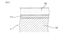
- Explanatory drawing which shows the cross-sectional structure in the surface vicinity of the pipe expansion plug in an Example.
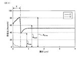
- Explanatory drawing which shows an example of the graph of the atomic number ratio of hydrogen and carbon with respect to the analysis depth of a DLC film in an Example.
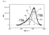
- Explanatory drawing which shows an example of the Raman spectrum of a DLC film in an Example.
- Explanatory drawing which shows an example of a structure of a heat exchanger.
- the tube expansion plug includes a plug main body, a base layer formed on the surface of the plug main body, and a DLC film formed on the base layer.
- a material of the plug body for example, a cemented carbide, SKD11 (tool steel) or the like can be used.
- the tube expansion plug has a slope or a curved surface on the surface for increasing the diameter of the metal tube. Specifically, the tube expansion plug generally has a region where the outer diameter increases from the front end side in the traveling direction toward the rear in the contact region with the inner surface of the metal tube.
- the tube expansion plug can be configured, for example, in a spherical shape, an elliptical spherical shape, a bullet shape, a polygonal pyramid shape, a conical shape, or a cylindrical shape in which a tapered region is provided in at least a part of the outer shape.
- the maximum diameter of the pipe expansion plug is the inner diameter of the metal pipe after the pipe expansion. Therefore, the maximum diameter of the tube expansion plug can be appropriately set according to the inner diameter of the metal tube.
- the maximum diameter of the expansion plug can be set in a range of 3 to 12 mm, for example.
- the shape of the plug body is the same as that of the tube expansion plug.
- the underlayer is composed of one or more selected from Si, Ti, Zr, V, Nb, Ta, Cr, Mo, and W. Preferably, it may be composed of one or more selected from Si, Cr, and W. These are easily industrially available. Of these, Si is similar in structure to C constituting the DLC film. Therefore, the base layer containing at least Si has high affinity with the DLC film. As a result, the adhesion between the underlayer and the DLC film can be further improved. In addition, W and Cr are often contained in the above-described materials constituting the plug body. Therefore, the base layer containing at least W or Cr has high affinity with the plug body. As a result, the adhesion between the base layer and the plug body can be further improved.
- the underlayer can be formed by physical vapor deposition such as ionized vapor deposition, ion plating, or sputtering.
- the underlayer can also be formed by chemical vapor deposition.
- the thickness of the underlayer is, for example, 0.5 to 5 ⁇ m.
- the adhesion between the plug body and the DLC film is further improved.
- the DLC film tends to be easily peeled when subjected to an external force.
- the stress applied to the DLC film is relieved and the DLC film is difficult to peel off.
- the adhesion between the underlayer and the DLC film is further improved.
- the ease of peeling of the DLC film can be measured by a critical load described later in Examples.
- the critical load is preferably 150 gf or more, and more preferably 500 gf or more.
- the DLC film can be formed by DLC treatment.
- DLC treatment There are roughly two types of DLC treatment, chemical vapor deposition (CVD) and physical vapor deposition (PVD). Among these, when the CVD method is used, a DLC film having a uniform thickness can be formed.
- CVD chemical vapor deposition
- PVD physical vapor deposition
- examples of the PVD method include an ionized vapor deposition method, an ion plating method, and a sputtering method.
- the DLC process is performed by the PVD method, not only hydrocarbon raw materials but also solid carbon raw materials can be used as raw materials. Therefore, the amount of hydrogen in the DLC film becomes, for example, about 0 to 15 atm%, and a hard DLC film can be formed.
- the ratio of the number of hydrogen atoms and the ratio of the number of carbon atoms in the DLC film are A H (atm%) and A C (atm%), respectively, the ratio A H / A C is 0 on average. 0.03 or more and 0.15 or less. If A H / A C is less than 0.03, the hydrogen becomes less contained in the DLC film, a carbon to each other in the DLC film to form a sp 2 hybrid orbital or sp 3 hybrid orbital, binding between carbon becomes solid. Therefore, the hardness of the DLC film becomes too high, and the DLC film may be broken by an external force applied to the DLC film during tube expansion processing.
- a H / A C is preferably 0.033 or more, and more preferably 0.035 or more.
- a H / A C exceeds 0.15, hydrogen contained in the DLC film increases. For this reason, carbon and hydrogen in the DLC film are combined to reduce the amount of carbon that can be adsorbed by the lubricating oil. Therefore, it becomes difficult for the lubricating oil to be adsorbed on the carbon atoms in the DLC film.
- a H / A C is preferably good 0.08 or less, more preferably 0.05 or less.
- a H / A C of the DLC film can be controlled by adjusting the production conditions of the DLC film.
- the composition of the raw material gas, the bias voltage during film deposition, by adjusting a deposition method or the like it is possible to control the A H / A C.
- increasing the hydrogen content of which is for example a hydrocarbon source gas it is possible to increase the A H / A C.
- methane it is possible to increase the A H / A C than with acetylene.
- the use of for example graphite as the raw material it is possible to reduce the A H / A C.
- the PVD method described above can use solid carbon as a film forming material. Therefore, the DLC film obtained by a PVD method, it is possible to reduce the A H / A C than DLC film obtained by a CVD method.
- the ratio A H (atm%) of the number of hydrogen atoms in the DLC film and the ratio A C (atm%) of the number of carbon atoms can be measured by glow discharge emission spectroscopic analysis of the DLC film.
- a tube expansion plug having a DLC film having an average A H / A C of 0.03 or more and 0.15 or less as described above based on the value measured by glow discharge optical emission spectrometry Suppression of adhesion of metal wear powder can be realized more reliably.
- the ratios PI G / PI D is less than 3. If PI G / PI D is 3 or more, and the hardness of the DLC film is too high, there is a possibility that the DLC film is broken during pipe expansion processing by processing conditions. In this case, the tube expansion load increases, and the friction between the metal tube and the tube expansion plug increases. Therefore, there is a possibility that the metal wear powder is likely to adhere to the tube expansion plug.
- PI G / PI D is preferably 2.5 or less, more preferably 2 or less.
- PI G / PI D is preferably 1 or more, more preferably 1.5 or more, more preferably 1.7 or more.
- PI G / PI D of the DLC film can be controlled by adjusting the production conditions of the DLC film. That is, PI G / PI D can be controlled by adjusting the composition of the source gas, the bias voltage during film formation, the vapor deposition method, and the like. Specifically, when a DLC film is manufactured, PI G / PI D can be increased by mixing a material containing, for example, a third component element (for example, Si) other than H and C into the source gas. Further, when the bias voltage at the time of film formation is increased, the hydrogen concentration is decreased, so that the density of the DLC film is increased. As a result, PI G / PI D can be reduced.
- the thickness of the DLC film is, for example, 0.1 to 5 ⁇ m.
- the time required for the isoparaffin or ⁇ -olefin to spread to a diameter of 15 mm after adding 2 ⁇ l of isoparaffin or ⁇ -olefin to the DLC film formed on the plate-shaped substrate is 80. It is preferable to employ a film that is within seconds. That is, in this case, the DLC film has excellent wettability with respect to an inexpensive lubricating oil mainly composed of isoparaffin or ⁇ -olefin. Therefore, even when pipe expansion is performed using a small amount of inexpensive lubricating oil, the pipe expansion load can be sufficiently reduced and adhesion of metal wear powder can be sufficiently suppressed.
- the metal tube examples include an aluminum tube, an aluminum alloy tube, and a copper tube.
- the metal tube is an aluminum tube or an aluminum alloy tube.
- Examples of the aluminum pipe and the aluminum alloy pipe include aluminum or aluminum alloys such as A1070, A1050, A1100, A1200, A3003, A3203, A5052, A5056, A5083, A6061, and A6063 defined in JIS H 4080 (2006).
- a tube made of can be used.
- the metal tube may have various irregularities such as a straight line and a spiral on the inner surface.
- the inner diameter of the metal tube is the diameter of a circle inscribed in the convex portion.
- the pipe expansion plug can be used in a state in which lubricating oil having a kinematic viscosity of 0.5 to 20 cSt at a temperature of 40 ° C. is present on at least the inner peripheral surface of the metal pipe.
- lubricating oil having a kinematic viscosity of 0.5 to 20 cSt at a temperature of 40 ° C.
- the kinematic viscosity of the lubricating oil is more preferably 1 cSt or more.
- the kinematic viscosity of the lubricating oil exceeds 20 cSt, it is difficult to sufficiently remove the lubricating oil even if the lubricating oil is removed after the pipe expansion process.
- the kinematic viscosity of the lubricating oil is more preferably 5 cSt or less, still more preferably 4 cSt or less, and even more preferably 3 cSt or less.
- the pipe expansion plug is used for insertion into the metal pipe for the refrigerant pipe arranged in the through hole provided in the plate-like fin material. More specifically, for example, it can be used as follows. First, the metal pipe for refrigerant
- the heat exchanger 5 can be manufactured by fitting the metal tube 2 and the fin material 4. Further, the metal pipe 2 can be expanded with a small amount of lubricating oil, so that expansion at a low cost is possible. Moreover, the residual oil in the metal pipe 2 after the pipe expansion process is reduced. Thereby, the request
- the metal tube is provided with the lubricating oil having a kinematic viscosity of 0.5 to 20 cSt at a temperature of 40 ° C. as described above between the metal tube and the tube expansion plug.
- the kinematic viscosity of the lubricating oil at a temperature of 40 ° C. is preferably 10 cSt or less, more preferably 5 cSt or less, and even more preferably 3 cSt or less.
- a lubricating oil containing at least one selected from mineral oil hydrocarbons, ⁇ -olefins, isoparaffins, and polybutenes as a base oil (main component) can be used.
- an oil-based agent can be further added to the base oil as necessary.
- the amount of oil-based agent added is, for example, 1 to 30 wt%.
- As the ⁇ -olefin, isoparaffin, and polybutene those having 10 to 18 carbon atoms can be used.
- As an oil-based agent 1 or more types chosen from a higher alcohol, a synthetic ester, a fatty acid, fats and oils, for example can be used.
- an available lubricating oil for tube expansion processing can be used. More specifically, for example, the lubricating oil disclosed in JP 2008-093713 A can be used.
- the main component of the lubricating oil is preferably isoparaffin or ⁇ -olefin.
- the lubricating oil becomes inexpensive and the pipe expansion cost of the metal pipe can be reduced.
- isoparaffin and ⁇ -olefin for example, those having 10 to 18 carbon atoms can be used. Further, in this case, since the wettability of the DLC film formed on the surface of the tube expansion plug with the lubricating oil is excellent, the amount of lubricating oil can be further reduced.
- Example 1 In this example, an example and a comparative example of a pipe expansion plug and a pipe expansion method of a metal pipe using the plug will be described.
- the tube expansion plug 1 of this example is used for forcibly inserting into the metal tube 2 to expand the outer diameter of the metal tube 2.
- the outer diameter D (maximum diameter) of the tube expansion plug 1 is larger than the inner diameter d of the metal tube 2.
- the tube expansion plug 1 includes a plug main body 10, a base layer 11 coated on the surface thereof, and a DLC film 12 coated thereon.
- a comparative tube expansion plug having a DLC film directly coated on the surface of the plug body portion without using a base layer is also used (not shown).
- the plug body 10 has a bullet shape
- the tube expansion plug 1 has a bullet shape as shown in FIG.
- the pipe expansion plug 1 is provided with a shaft portion 19 having a smaller diameter than the pipe expansion plug 1 extended from the pipe expansion plug 1 in order to allow the pipe expansion plug 1 to enter the metal pipe 2.
- the shaft portion 19 is brazed to the tube expansion plug 1.
- samples P1 to P6 were prepared as the pipe expansion plug 1 (see Table 1 described later).
- Each of the plug body portions 10 of these tube expansion plugs 1 is made of a cemented carbide.
- the cemented carbide contains tungsten carbide and cobalt.
- the base layer 11 is coated on the outer peripheral surface of the plug main body 10
- the DLC film 12 is coated on the base layer 11 (FIG. 2).
- the components constituting the foundation layer are shown in Table 1 described later.
- the sample P3 there is no base layer, and the outer peripheral surface of the plug body is directly covered with the DLC film (not shown).
- the pipe expansion plugs of each sample was calculated by the A H / A C and PI G / PI D as follows. ⁇ A H /A C Nosanshutsu_> A H / A C was measured by glow discharge optical emission spectrometry (GD-OES analysis).
- the DLC film of each sample was analyzed in the depth direction of the DLC film using a glow discharge emission analyzer (“GDA750” manufactured by RIGAKU).
- the analysis conditions were power: 25 W, argon gas pressure: 3.5 hPa, anode diameter: 2.5 mm ⁇ , and sampling rate: 5 ms.
- a graph of the ratio of the number of atoms of hydrogen (H) and carbon (C) with respect to the analysis depth was created from the measured value of the reached depth after the analysis and the analysis time.
- the result of the sample P3 is shown in FIG.
- the average value of the maximum value (A Cmax ) and the minimum value (A Cmax ) of the carbon atom number ratio was calculated from the analysis result, and this average value was defined as the carbon half value (A Chalf ) (see FIG. 3).
- the depth to give the half value of carbon (A Chalf ) was defined as the thickness (T) of the DLC film.
- ⁇ Calculation of PI G / PI D is performed by Raman spectroscopy.
- a Raman spectrum of the DLC film was obtained using a Raman spectrometer (“NRS-1000” manufactured by JEOL Ltd.). A green laser with a wavelength of 534 nm was used as the excitation light source.
- FIG. 4 shows the Raman spectrum 3 of the DLC film of the sample P3.
- the horizontal axis indicates the wave number (cm ⁇ 1 ), and the vertical axis indicates the intensity. From the obtained Raman spectrum, peaks were separated PI D peak PI G and D bands 32 of G-band 31 (see FIG. 4).
- the DLC film formed on the tube expansion plug of each sample was evaluated for wet spreadability as follows. ⁇ Wet spreadability> A DLC film formed on a flat plate under the same conditions as the DLC film of each sample was prepared. The DLC film formed on this flat plate has the same composition and structure as the DLC film of each sample. Next, 2 ⁇ l of isoparaffin (“Isol 400” manufactured by JX Nippon Oil & Energy Corporation) was dropped on the DLC film formed on the flat plate using a syringe. The dripping was performed by grounding the tip of the syringe on the DLC film.
- Isol 400 manufactured by JX Nippon Oil & Energy Corporation
- the critical load was measured about the DLC film formed in the pipe expansion plug of each sample as follows.
- the scratch test was performed using a Haydon friction tester (“HHS-2000” manufactured by Shinto Kagaku Co., Ltd.). Specifically, a diamond indenter is placed on a DLC film formed on a cemented carbide plate whose surface is mirror-finished, and each diamond indenter is applied while increasing the load applied to the DLC film in the range of 0 to 1000 gf. The sample was slid on the DLC film. At this time, the sliding trace was observed, the load when the exposure of the carbide of each sample started was measured, and this was defined as the critical load (gf). The results are shown in Table 1.
- a JIS A3003 aluminum alloy tube (aluminum tube) having an outer diameter of 7.0 mm and an inner straight groove is produced using a tube expansion plug (samples P1 to P6) having a maximum diameter of 6 mm.
- the aluminum tube has a groove depth (fin height) of 300 ⁇ m, a bottom thickness (thickness from the groove bottom to the outer peripheral surface) of 475 ⁇ m, and a number of strips of 36. Specifically, as shown in FIG.
- the aluminum tube 2 in which a plurality of straight grooves (not shown) extending in the axial direction of the aluminum tube 2 are formed on the inner surface 21 is fixed so that the axial direction is a vertical direction.
- the lubricating oil was supplied from the upper side to the lower side in the vertical direction, and the lubricating oil was supplied to the inner surface 21 of the aluminum tube 2.
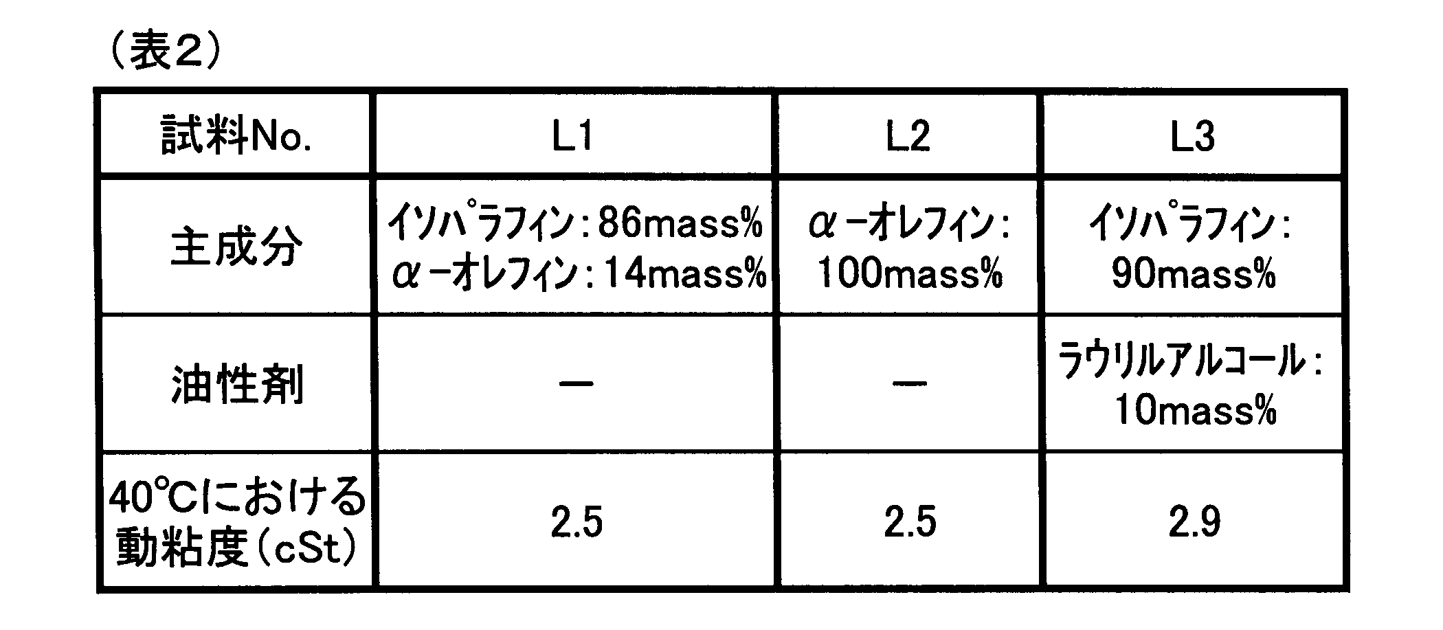
- the composition of the lubricating oil is shown in Table 2.
- the tube expansion plug 1 (samples P1 to P6) is inserted into the aluminum tube 2, a predetermined load is applied to the shaft portion 19, and the tube expansion plug 1 is advanced in the axial direction from above in the vertical direction to form an aluminum tube. 2 tube expansion processing was performed.
- the moving speed (tube expansion speed) of the tube expansion plug 1 in the aluminum tube 2 was 50 mm / min.
- the five types of pipe expansion plugs (samples P1 to P6) shown in Table 1 above and the three types of lubricating oils (samples L1 to L3) shown in Table 2 below are combined to form a table described later.
- Seven types of tube expansion processing (Test Example 1 to Test Example 8) shown in Fig. 3 were performed.
- the wear properties of the DLC films formed on the expanded plugs of the samples P1 to P6 were evaluated as follows. ⁇ Abrasion> The wear of the DLC film was evaluated by a pin-on-disk test. First, a DLC film was formed on a cemented carbide disk whose surface was mirror-polished under the same conditions as the DLC films of the samples P1 to P6 described above. The DLC film formed on the disk has the same composition and structure as the DLC film of each sample described above. Next, three A3003 aluminum pins having a diameter of 5 mm and a length of 10 mm were prepared as pins for a pin-on-disk test, and the tip on one side thereof was a curved surface of R2.5.
- the curved surface side of the pin was brought into contact with the DLC film formed on the disk, and the disk was rotated while supplying lubricating oil (samples L1 to L3), and the pin of the pin-on-disk test apparatus was slid on the DLC film.
- the rotational speed of the disk was 250 rpm
- the rotational radius was 22.5 mm
- the sliding time was 100 minutes.
- the pin-on-disk test was done about the DLC film of each sample.
- sample P2 and the sample P6 are tube expansion plugs according to the example, and the other samples are tube expansion plugs according to the comparative example.
- Test Example 2 Test Example 6, Test Example 7, and Test Example 8 are tube expansion methods according to Examples, and the other test examples are tube expansion methods according to Comparative Examples.
Landscapes
- Chemical & Material Sciences (AREA)
- Chemical Kinetics & Catalysis (AREA)
- General Chemical & Material Sciences (AREA)
- Oil, Petroleum & Natural Gas (AREA)
- Organic Chemistry (AREA)
- Engineering & Computer Science (AREA)
- Mechanical Engineering (AREA)
- Lubricants (AREA)
- Mounting, Exchange, And Manufacturing Of Dies (AREA)
- Chemical Vapour Deposition (AREA)
Abstract
金属管(2)内にその内径よりも大きな外径を有する拡管プラグ(1)を強制的に挿入して金属管の外径を拡張させるために用いられる拡管プラグ及びこれを用いた拡管方法である。拡管プラグは、プラグ本体部(10)と、その表面に被覆された下地層(11)と、その上に被覆されたDLC膜(12)とを有する。DLC膜中の水素原子数の割合AH(atm%)と炭素原子数の割合AC(atm%)との比AH/AC が平均で0.03以上かつ0.15以下である。また、DLC膜のラマンスペクトルにおけるGバンドのピーク強度PIGとDバンドのピーク強度PIDとの比PIG/PIDが3未満である。
Description
本発明は、金属管の拡管に用いる拡管プラグ、及びこれを用いた金属管の拡管方法に関する。
冷蔵庫や空調用エアコンディショナーには、一般にクロスフィンチューブタイプの熱交換器が用いられている。この熱交換器は、空気側のフィン材と、冷媒側の金属管からなる冷媒配管とから構成されている。
このようなクロスフィンチューブタイプの熱交換器は、一般に、次のようにして作製されている。
まず、所定のカラー部を有するフィン材が積層される。次いで、円筒状のカラー部内に金属管が挿入される。その後、金属管内に金属管の内径よりも大きな外径を有する拡管プラグが強制的に挿入されて金属管の外径が拡張される拡管加工が行われる。これにより、金属管がフィン材に固着される。その結果、クロスフィンチューブタイプの熱交換器が得られる。金属管としては、銅管あるいはアルミニウム管等が用いられている。
まず、所定のカラー部を有するフィン材が積層される。次いで、円筒状のカラー部内に金属管が挿入される。その後、金属管内に金属管の内径よりも大きな外径を有する拡管プラグが強制的に挿入されて金属管の外径が拡張される拡管加工が行われる。これにより、金属管がフィン材に固着される。その結果、クロスフィンチューブタイプの熱交換器が得られる。金属管としては、銅管あるいはアルミニウム管等が用いられている。
近年、家電製品の小型化、高性能化、高信頼性化、低コスト化がさらに求められている。そして、熱交換器に用いられる金属管においても、従来以上の高信頼性および低コスト化が要求されている。信頼性向上のためには、金属管内の残留油を少なくする必要がある。また、低コスト化のためには加工時に使用される潤滑油量を低減させる必要がある。
そこで、拡管加工の際には、拡管冶具と金属管との摩擦を低減しつつ潤滑油量を少なくするために、高粘度の潤滑油が用いられていた。拡管加工後の金属管内に付着した潤滑油は、揮発させて除去される。しかし、一般的に粘度の高い潤滑油は揮発性に劣る。そのため、除去工程においても潤滑油が十分に除去されず、金属管内に残留するおそれがあった。その結果、熱交換器の信頼性が低下するおそれがあった。また、コスト低減のために潤滑油量が減らされると、拡管冶具と金属管とが焼付くおそれがあった。その結果、拡管加工を行うことができなくなるおそれがあった。
そこで、ダイヤモンドライクカーボン(以下、適宜「DLC」という)皮膜を形成した拡管治具を用いることにより、拡管加工に使用する潤滑油量の低減を図る技術が開発されている(特許文献1参照)。
また、DLC膜を用いたその他の技術としては、摺動部材の表面にDLC膜を形成する技術(特許文献2参照)や、被加工面との当接面にDLC膜等の硬質炭素被膜を備えた転造加工用工具に関する技術が開発されている(特許文献3参照)。
また、DLC膜を用いたその他の技術としては、摺動部材の表面にDLC膜を形成する技術(特許文献2参照)や、被加工面との当接面にDLC膜等の硬質炭素被膜を備えた転造加工用工具に関する技術が開発されている(特許文献3参照)。
しかしながら、どのようなDLC膜が拡管プラグに適しているかはこれまで明かにされていない。したがって、DLC膜を形成した拡管プラグを用いても、必ずしも拡管荷重を充分に低くすることはできていない。特に、アルミニウム管のような金属管は、摩擦抵抗が大きいため、拡管加工時における拡管荷重が大きくなりやすい。そのため、潤滑油を使用していても、拡管プラグと金属管との摩擦が大きくなり、金属の摩耗粉が発生するおそれがある。そして、この摩耗粉が拡管プラグに凝着すると、拡管荷重がさらに高くなるという悪循環を引き起こすとともに、拡管プラグの寿命が低下する。そこで、DLC膜を備えた拡管プラグの更なる改良が望まれている。
本発明は、かかる背景に鑑みてなされたものであり、少量の潤滑油でも拡管荷重を充分かつ確実に小さくすることができると共に、金属摩耗粉の凝着を充分かつ確実に抑制することができ、さらに耐久性に優れた拡管プラグ、及びこれを用いた金属管の加工方法を提供しようとするものである。
本発明の一態様は、金属管内に該金属管の内径よりも大きな外径を有する拡管プラグを強制的に挿入して上記金属管の外径を拡張させるために用いられる拡管プラグであって、
該拡管プラグは、プラグ本体部と、該プラグ本体部の表面に被覆された下地層と、該下地層上に被覆されたダイヤモンドライクカーボン膜とを有し、
上記下地層は、Si、Ti、Zr、V、Nb、Ta、Cr、Mo、Wから選ばれる1種または2種以上からなり、
上記ダイヤモンドライクカーボン膜中の水素原子数の割合AH(atm%)と炭素原子数の割合AC(atm%)との比AH/ACが、平均で0.03以上かつ0.15以下であり、
上記ダイヤモンドライクカーボン膜のラマンスペクトルにおけるGバンドのピーク強度PIGとDバンドのピーク強度PIDとの比PIG/PIDが3未満であることを特徴とする拡管プラグにある。
該拡管プラグは、プラグ本体部と、該プラグ本体部の表面に被覆された下地層と、該下地層上に被覆されたダイヤモンドライクカーボン膜とを有し、
上記下地層は、Si、Ti、Zr、V、Nb、Ta、Cr、Mo、Wから選ばれる1種または2種以上からなり、
上記ダイヤモンドライクカーボン膜中の水素原子数の割合AH(atm%)と炭素原子数の割合AC(atm%)との比AH/ACが、平均で0.03以上かつ0.15以下であり、
上記ダイヤモンドライクカーボン膜のラマンスペクトルにおけるGバンドのピーク強度PIGとDバンドのピーク強度PIDとの比PIG/PIDが3未満であることを特徴とする拡管プラグにある。
本発明の他の態様は、金属管内に上記拡管プラグを強制的に挿入して上記金属管の外径を拡張させる金属管の拡管方法であって、
上記金属管と上記拡管プラグとの間に、温度40℃における動粘度が0.5~20cStである潤滑油を存在させた状態で上記金属管の拡管を行うことを特徴とする金属管の拡管方法にある。
上記金属管と上記拡管プラグとの間に、温度40℃における動粘度が0.5~20cStである潤滑油を存在させた状態で上記金属管の拡管を行うことを特徴とする金属管の拡管方法にある。
上記拡管プラグは、その表面に、AH/AC及びPIG/PIDが上記特定の範囲にあるDLC膜を有している。即ち、上記拡管プラグにおいては、DLC膜の組成(H原子数割合とC原子数割合との比AH/ACの平均)及び構造(ラマンスペクトルにおけるGバンドとDバンドとのピーク強度比PIG/PID)が上記特定の範囲に制御されている。このような組成及び構造を有するDLC膜を備えているため、上記拡管プラグは、少量の潤滑油でも拡管加工における拡管荷重を充分かつ確実に小さくすることができる。また、上記拡管プラグは、拡管加工における金属摩耗粉の凝着を充分かつ確実に抑制することができる。また、上記DLC膜は、耐久性に優れており、拡管プラグの耐久性を向上させることができる。
また、上記拡管プラグは、プラグ本体部とDLC膜との間に、上記特定成分からなる下地層を有している。該下地層の存在により、上記拡管プラグにおけるDLC膜の密着性が向上している。そのため、DLC膜がプラグ本体部から剥がれ難い。それ故、拡管プラグは、DLC膜が有する上述の性能を充分に発揮することができる。
また、上記金属管の拡管方法においては、上記特定のDLC膜及び下地層を有する上述の拡管プラグが用いられている。そのため、金属管と拡管プラグとの間に、温度40℃における動粘度が0.5~20cStである低粘度の潤滑油を少量用いても、拡管時における拡管荷重を充分かつ確実に小さくすることができると共に、金属摩耗粉の凝着を充分かつ確実に抑制することができる。
また、拡管プラグのDLC膜は耐久性にも優れているため、長期間安定して金属管の拡管を行うことが可能になる。
また、拡管プラグのDLC膜は耐久性にも優れているため、長期間安定して金属管の拡管を行うことが可能になる。
次に、上記拡管プラグ及び上記拡管方法の好ましい実施形態について説明する。
上記拡管プラグは、プラグ本体部と、該プラグ本体部の表面に形成された下地層と、該下地層上に形成されたDLC膜とを有する。
プラグ本体部の材質としては、例えば、超硬合金、SKD11(工具鋼)等を用いることができる。
拡管プラグは、表面に、金属管の径を大きくするための斜面又は曲面を有している。具体的には、拡管プラグは、金属管の内面との接触領域において、一般に、進行方向の先端側から後方に向けて外径が大きくなる領域を有する。より具体的には、拡管プラグは、例えば球形状、楕円球形、弾丸形状、多角錐形状、円錐形状、又は外形の少なくとも一部にテーパ領域を設けた円柱形状等により構成することができる。一般に、拡管プラグの最大径が拡管後の金属管の内径となる。したがって、拡管プラグの最大径は、金属管の内径に応じて適宜設定することができる。拡管プラグの最大径は、例えば3~12mmの範囲に設定することができる。プラグ本体部の形状も拡管プラグの形状と同様である。
上記拡管プラグは、プラグ本体部と、該プラグ本体部の表面に形成された下地層と、該下地層上に形成されたDLC膜とを有する。
プラグ本体部の材質としては、例えば、超硬合金、SKD11(工具鋼)等を用いることができる。
拡管プラグは、表面に、金属管の径を大きくするための斜面又は曲面を有している。具体的には、拡管プラグは、金属管の内面との接触領域において、一般に、進行方向の先端側から後方に向けて外径が大きくなる領域を有する。より具体的には、拡管プラグは、例えば球形状、楕円球形、弾丸形状、多角錐形状、円錐形状、又は外形の少なくとも一部にテーパ領域を設けた円柱形状等により構成することができる。一般に、拡管プラグの最大径が拡管後の金属管の内径となる。したがって、拡管プラグの最大径は、金属管の内径に応じて適宜設定することができる。拡管プラグの最大径は、例えば3~12mmの範囲に設定することができる。プラグ本体部の形状も拡管プラグの形状と同様である。
また、上記下地層は、Si、Ti、Zr、V、Nb、Ta、Cr、Mo、Wから選ばれる1種または2種以上からなる。好ましくは、Si、Cr、Wから選ばれる1種又は2種以上からなることがよい。これらは工業的に入手が容易である。また、これらのうちSiは、DLC膜を構成するCと構造が似ている。そのため、少なくともSiを含む下地層はDLC膜との親和性が高い。その結果、下地層とDLC膜との密着性をより高めることができる。また、W及びCrは、プラグ本体を構成する上述の材質に含まれていることが多い。そのため、少なくともW又はCrを含有する下地層は、プラグ本体との親和性が高い。その結果、下地層とプラグ本体との密着性をより高めることができる。下地層は、イオン化蒸着法、イオンプレーティング法、スパッタ法等の物理蒸着法により形成することができる。また、下地層は、化学蒸着法により形成することもできる。
下地層の厚さは、例えば0.5~5μmである。
下地層の厚さは、例えば0.5~5μmである。
DLC膜とプラグ本体部との間に下地層があると、プラグ本体部とDLC膜との密着性がより向上する。DLC膜は、外力を受けると剥離し易いという傾向がある。しかし、上記のように、下地層があるとDLC膜にかかる応力が緩和され、DLC膜が剥離し難くなる。また、DLC膜と下地層との間には、両者の構成成分が互いに拡散した拡散部が存在していてもよい。この場合には、下地層とDLC膜との密着性がさらに向上する。DLC膜の剥離しやすさは、実施例において後述する臨界荷重により測定することができる。臨界荷重は150gf以上であることが好ましく、500gf以上であることがより好ましい。
また、DLC膜は、DLC処理により形成することができる。DLC処理には、大別して化学蒸着法(CVD法)と物理蒸着法(PVD法)の2種類が存在する。
これらのうちCVD法を用いると、厚みが均一なDLC膜を形成することができる。
これらのうちCVD法を用いると、厚みが均一なDLC膜を形成することができる。
また、PVD法としては、イオン化蒸着法、イオンプレーティング法、スパッタリング法等が挙げられる。PVD法によってDLC処理を行う場合には、原料として、炭化水素原料だけでなく固体炭素原料を用いることができる。そのため、DLC膜中の水素量が例えば0~15atm%程度になり、硬質なDLC膜の形成が可能になる。
拡管プラグにおいては、DLC膜中の水素原子数の割合及び炭素原子数の割合をそれぞれAH(atm%)及びAC(atm%)とすると、これらの比AH/ACが平均で0.03以上かつ0.15以下である。
AH/ACが0.03未満の場合には、DLC膜中に含まれる水素が少なくなり、DLC膜中の炭素同士がsp2混成軌道やsp3混成軌道を形成し、炭素間の結合が強固になる。そのため、DLC膜の硬度が高くなり過ぎて、拡管加工時にDLC膜にかかる外力によりDLC膜が割れてしまうおそれがある。また、この場合には、拡管荷重が大きくなり、金属管と拡管プラグとの摩擦が大きくなり金属摩耗粉が拡管プラグに凝着し易くなるおそれがある。AH/ACは、好ましくは0.033以上がよく、より好ましくは0.035以上がよい。一方、AH/ACが0.15を超える場合には、DLC膜中に含まれる水素が多くなる。そのため、DLC膜中の炭素と水素とが結合し、潤滑油が吸着できる炭素が少なくなる。それ故、潤滑油がDLC膜中の炭素原子に吸着し難くなる。その結果、DLC膜の表面で潤滑油が濡れ広がり難くなり、潤滑油を用いて拡管を行う際に局所的な油切れが起きやすくなる。また、この場合には、炭素同士のsp2混成軌道が不規則になりやすい。そのため、DLC膜の硬度が小さくなり、DLC膜が摩耗しやすくなる。その結果、拡管プラグの寿命が低下するおそれがある。さらに、AH/ACが大きい場合には、炭素の不対電子が少なくなる。そのため、例え油性剤を含有する潤滑油を用いても、油性剤がDLC膜に吸着しにくくなる。それ故、例え潤滑油に油性剤を添加したとしても油性剤の効果が小さくなる。AH/ACは、好ましくは0.08以下がよく、より好ましくは0.05以下がよい。
AH/ACが0.03未満の場合には、DLC膜中に含まれる水素が少なくなり、DLC膜中の炭素同士がsp2混成軌道やsp3混成軌道を形成し、炭素間の結合が強固になる。そのため、DLC膜の硬度が高くなり過ぎて、拡管加工時にDLC膜にかかる外力によりDLC膜が割れてしまうおそれがある。また、この場合には、拡管荷重が大きくなり、金属管と拡管プラグとの摩擦が大きくなり金属摩耗粉が拡管プラグに凝着し易くなるおそれがある。AH/ACは、好ましくは0.033以上がよく、より好ましくは0.035以上がよい。一方、AH/ACが0.15を超える場合には、DLC膜中に含まれる水素が多くなる。そのため、DLC膜中の炭素と水素とが結合し、潤滑油が吸着できる炭素が少なくなる。それ故、潤滑油がDLC膜中の炭素原子に吸着し難くなる。その結果、DLC膜の表面で潤滑油が濡れ広がり難くなり、潤滑油を用いて拡管を行う際に局所的な油切れが起きやすくなる。また、この場合には、炭素同士のsp2混成軌道が不規則になりやすい。そのため、DLC膜の硬度が小さくなり、DLC膜が摩耗しやすくなる。その結果、拡管プラグの寿命が低下するおそれがある。さらに、AH/ACが大きい場合には、炭素の不対電子が少なくなる。そのため、例え油性剤を含有する潤滑油を用いても、油性剤がDLC膜に吸着しにくくなる。それ故、例え潤滑油に油性剤を添加したとしても油性剤の効果が小さくなる。AH/ACは、好ましくは0.08以下がよく、より好ましくは0.05以下がよい。
DLC膜のAH/ACは、DLC膜の製造条件を調整することにより制御することができる。即ち、例えば原料ガスの組成、成膜時のバイアス電圧、蒸着方法等を調整することにより、AH/ACを制御することができる。
具体的には、原料ガスである例えば炭化水素の水素含有量を増やすと、AH/ACを大きくすることができる。例えば、メタンを用いた場合には、アセチレンを用いた場合よりもAH/ACを大きくすることができる。また、原料として例えば黒鉛を用いると、AH/ACを小さくすることができる。
また、成膜時のバイアス電圧を高くするほどAH/ACを小さくすることができる。
また、上述のPVD法は、成膜原料として固体の炭素を使うことができる。そのため、PVD法により得られるDLC膜は、CVD法により得られるDLC膜よりもAH/ACを小さくすることができる。
具体的には、原料ガスである例えば炭化水素の水素含有量を増やすと、AH/ACを大きくすることができる。例えば、メタンを用いた場合には、アセチレンを用いた場合よりもAH/ACを大きくすることができる。また、原料として例えば黒鉛を用いると、AH/ACを小さくすることができる。
また、成膜時のバイアス電圧を高くするほどAH/ACを小さくすることができる。
また、上述のPVD法は、成膜原料として固体の炭素を使うことができる。そのため、PVD法により得られるDLC膜は、CVD法により得られるDLC膜よりもAH/ACを小さくすることができる。
DLC膜中の水素原子数の割合AH(atm%)及び炭素原子数の割合AC(atm%)は、DLC膜のグロー放電発光分光分析により測定することができる。
グロー放電発光分光分析により測定された値に基づいたAH/ACが上述のごとく平均で0.03以上かつ0.15以下のDLC膜を有する拡管プラグを用いることにより、拡管荷重の低下及び金属摩耗粉の凝着抑制がより確実に実現されうる。
グロー放電発光分光分析により測定された値に基づいたAH/ACが上述のごとく平均で0.03以上かつ0.15以下のDLC膜を有する拡管プラグを用いることにより、拡管荷重の低下及び金属摩耗粉の凝着抑制がより確実に実現されうる。
また、DLC膜のラマンスペクトルにおけるGバンドのピーク強度及びDバンドのピーク強度をそれぞれPIG及びPIDとすると、これらの比PIG/PIDが3未満である。
PIG/PIDが3以上の場合には、DLC膜の硬度が高くなり過ぎて、加工条件によっては拡管加工時にDLC膜が割れるおそれがある。また、この場合には、拡管荷重が大きくなり、金属管と拡管プラグとの摩擦が大きくなる。そのため、金属摩耗粉が拡管プラグに凝着し易くなるおそれがある。PIG/PIDは、好ましくは2.5以下がよく、より好ましくは2以下がよい。また、PIG/PIDが小さくなりすぎると、DLC膜の硬度が低くなり、DLC膜が摩耗しやすくなる。かかる観点から、PIG/PIDは、1以上が好ましく、1.5以上がより好ましく、1.7以上がさらに好ましい。
PIG/PIDが3以上の場合には、DLC膜の硬度が高くなり過ぎて、加工条件によっては拡管加工時にDLC膜が割れるおそれがある。また、この場合には、拡管荷重が大きくなり、金属管と拡管プラグとの摩擦が大きくなる。そのため、金属摩耗粉が拡管プラグに凝着し易くなるおそれがある。PIG/PIDは、好ましくは2.5以下がよく、より好ましくは2以下がよい。また、PIG/PIDが小さくなりすぎると、DLC膜の硬度が低くなり、DLC膜が摩耗しやすくなる。かかる観点から、PIG/PIDは、1以上が好ましく、1.5以上がより好ましく、1.7以上がさらに好ましい。
DLC膜のPIG/PIDは、DLC膜の製造条件を調整することにより制御することができる。即ち、例えば原料ガスの組成、成膜時のバイアス電圧、蒸着方法等を調整することにより、PIG/PIDを制御することができる。
具体的には、DLC膜の製造時に、例えばH及びC以外の第三成分元素(例えばSi等)を含む物質を原料ガスに混合することにより、PIG/PIDを大きくすることができる。また、成膜時のバイアス電圧を高くすると水素濃度が低くなるため、DLC膜の密度が高くなる。その結果、PIG/PIDを小さくすることができる。
DLC膜の厚さは例えば0.1~5μmである。
具体的には、DLC膜の製造時に、例えばH及びC以外の第三成分元素(例えばSi等)を含む物質を原料ガスに混合することにより、PIG/PIDを大きくすることができる。また、成膜時のバイアス電圧を高くすると水素濃度が低くなるため、DLC膜の密度が高くなる。その結果、PIG/PIDを小さくすることができる。
DLC膜の厚さは例えば0.1~5μmである。
拡管プラグ用のDLC膜としては、板状の基材上に形成したDLC膜に2μlのイソパラフィン又はα-オレフィンをしてから上記イソパラフィン又は上記α-オレフィンが直径15mmに広がるまでに要する時間が80秒以内となる膜が採用されていることが好ましい。
即ち、この場合には、イソパラフィン又はα-オレフィンを主成分とする安価な潤滑油に対するDLC膜の濡れ広がり性が優れている。そのため、安価な潤滑油を少量用いて拡管加工を行っても拡管荷重を充分に低くし、金属摩耗粉の凝着を充分に抑制することができる。
即ち、この場合には、イソパラフィン又はα-オレフィンを主成分とする安価な潤滑油に対するDLC膜の濡れ広がり性が優れている。そのため、安価な潤滑油を少量用いて拡管加工を行っても拡管荷重を充分に低くし、金属摩耗粉の凝着を充分に抑制することができる。
上記金属管としては、アルミニウム管、アルミニウム合金管、銅管等がある。
好ましくは、上記金属管は、アルミニウム管又はアルミニウム合金管であることがよい。
この場合には、拡管荷重を小さくし、金属摩耗粉の凝着を抑制し、耐久性に優れるという上記拡管プラグの優れた作用効果をより際立たせることができる。
即ち、一般に、アルミニウム管及びアルミニウム合金管は、摩擦係数が大きい。そのため、拡管加工時に拡管荷重が大きくなり、潤滑油を使用していても、拡管プラグと金属管との摩擦が大きくなり、金属の摩耗粉が発生するおそれがある。上記拡管プラグを用いることにより、これらの問題を回避することができる。
好ましくは、上記金属管は、アルミニウム管又はアルミニウム合金管であることがよい。
この場合には、拡管荷重を小さくし、金属摩耗粉の凝着を抑制し、耐久性に優れるという上記拡管プラグの優れた作用効果をより際立たせることができる。
即ち、一般に、アルミニウム管及びアルミニウム合金管は、摩擦係数が大きい。そのため、拡管加工時に拡管荷重が大きくなり、潤滑油を使用していても、拡管プラグと金属管との摩擦が大きくなり、金属の摩耗粉が発生するおそれがある。上記拡管プラグを用いることにより、これらの問題を回避することができる。
上記アルミニウム管、アルミニウム合金管としては、例えば、JIS H 4080(2006年)に規定されるA1070、A1050、A1100、A1200、A3003、A3203、A5052、A5056、A5083、A6061、A6063等のアルミニウム又はアルミニウム合金からなる管を用いることができる。
上記金属管には、内面に直線状、螺旋状等の種々の凹凸が形成されていてもよい。この場合の金属管の内径は、凸部に内接する円の直径となる。
上記拡管プラグは、温度40℃における動粘度が0.5~20cStである潤滑油を上記金属管の少なくとも内周面に存在させた状態で用いることができる。
潤滑油の動粘度が0.5cSt未満の場合には、潤滑性が不足するおそれがある。潤滑油の動粘度は、より好ましくは1cSt以上がよい。一方、潤滑油の動粘度が20cStを超える場合には、拡管加工後に潤滑油の除去を行っても潤滑油を十分に除去することが困難になる。その結果、金属管内における残油量が増加するおそれがある。潤滑油の動粘度は、より好ましくは5cSt以下がよく、さらに好ましくは4cSt以下がよく、さらにより好ましくは3cSt以下がよい。
潤滑油の動粘度が0.5cSt未満の場合には、潤滑性が不足するおそれがある。潤滑油の動粘度は、より好ましくは1cSt以上がよい。一方、潤滑油の動粘度が20cStを超える場合には、拡管加工後に潤滑油の除去を行っても潤滑油を十分に除去することが困難になる。その結果、金属管内における残油量が増加するおそれがある。潤滑油の動粘度は、より好ましくは5cSt以下がよく、さらに好ましくは4cSt以下がよく、さらにより好ましくは3cSt以下がよい。
上記拡管プラグは、プレート状のフィン材に設けた貫通穴内に配置した冷媒配管用の上記金属管内に挿入するために用いられる。より具体的には、例えば次のようにして用いることできる。まず、プレート状のフィン材に設けた貫通穴内に、冷媒配管用の金属管が挿入される。次いで、金属管の内径よりも大きな外径を有する拡管プラグが金属管内に強制的に挿入される。これにより、金属管の外径が拡張され、貫通穴の内壁と金属管の外側面とが嵌合する。即ち、拡管プラグは、例えば冷媒配管用の金属管とフィン材との嵌合に用いられえる。この場合には、例えば、図5に示すように、金属管2とフィン材4とを嵌合して、熱交換器5を作製することができる。また、少ない潤滑油量で、金属管2の拡管が可能になり、低コストでの拡管が可能になる。また、拡管加工後の金属管2内の残留油が減少する。これにより、熱交換器5における高信頼性及び低コスト化の要求に応えることができる。
上記金属管の拡管方法においては、上記金属管と上記拡管プラグとの間に、上述のように温度40℃における動粘度が0.5~20cStである潤滑油を存在させた状態で上記金属管の拡管を行うことができる。温度40℃における潤滑油の動粘度は、10cSt以下であることが好ましく、5cSt以下であることがより好ましく、3cSt以下であることがさらに好ましい。
具体的には、例えば鉱油系炭化水素、α-オレフィン、イソパラフィン、ポリブテンから選ばれる1種以上を基油(主成分)として含有する潤滑油を用いることができる。また、上記基油には、必要に応じてさらに油性剤を添加することができる。油性剤の添加量は、例えば1~30wt%である。なお、α-オレフィン、イソパラフィン、ポリブテンとしては、炭素数が10~18のものを用いることができる。また、油性剤としては、例えば高級アルコール、合成エステル、脂肪酸、油脂から選ばれる1種以上を用いることができる。
潤滑油としては、上記動粘度範囲を満足すれば、入手可能な拡管加工用の潤滑油を用いることができる。より具体的には例えば特開2008-093713号公報に開示された潤滑油などを用いることができる。
具体的には、例えば鉱油系炭化水素、α-オレフィン、イソパラフィン、ポリブテンから選ばれる1種以上を基油(主成分)として含有する潤滑油を用いることができる。また、上記基油には、必要に応じてさらに油性剤を添加することができる。油性剤の添加量は、例えば1~30wt%である。なお、α-オレフィン、イソパラフィン、ポリブテンとしては、炭素数が10~18のものを用いることができる。また、油性剤としては、例えば高級アルコール、合成エステル、脂肪酸、油脂から選ばれる1種以上を用いることができる。
潤滑油としては、上記動粘度範囲を満足すれば、入手可能な拡管加工用の潤滑油を用いることができる。より具体的には例えば特開2008-093713号公報に開示された潤滑油などを用いることができる。
上記潤滑油の主成分は、イソパラフィン又はα-オレフィンであることが好ましい。
この場合には、潤滑油が安価になり、金属管の拡管コストを下げることができる。イソパラフィン及びα-オレフィンとしては、例えば炭素数10~18のものを用いることができる。また、この場合には、上記拡管プラグの表面に形成されたDLC膜に対する上記潤滑油との濡れ広がり性が優れるため、潤滑油量のより一層の低減化を図ることができる。
この場合には、潤滑油が安価になり、金属管の拡管コストを下げることができる。イソパラフィン及びα-オレフィンとしては、例えば炭素数10~18のものを用いることができる。また、この場合には、上記拡管プラグの表面に形成されたDLC膜に対する上記潤滑油との濡れ広がり性が優れるため、潤滑油量のより一層の低減化を図ることができる。
(実施例1)
本例においては、拡管プラグ、及びこれを用いた金属管の拡管方法の実施例及び比較例について説明する。
図1に示すごとく、本例の拡管プラグ1は、金属管2内に強制的に挿入して金属管2の外径を拡張させるために用いられる。拡管プラグ1の外径D(最大径)は、金属管2の内径dよりも大きくなっている。図2に示すごとく、拡管プラグ1は、プラグ本体部10と、その表面に被覆された下地層11と、その上に被覆されたDLC膜12とを有する。また、本例においては、下地層を有さず、プラグ本体部の表面に直接被覆されたDLC膜を有する比較用の拡管プラグも用いる(図示略)。
本例においては、拡管プラグ、及びこれを用いた金属管の拡管方法の実施例及び比較例について説明する。
図1に示すごとく、本例の拡管プラグ1は、金属管2内に強制的に挿入して金属管2の外径を拡張させるために用いられる。拡管プラグ1の外径D(最大径)は、金属管2の内径dよりも大きくなっている。図2に示すごとく、拡管プラグ1は、プラグ本体部10と、その表面に被覆された下地層11と、その上に被覆されたDLC膜12とを有する。また、本例においては、下地層を有さず、プラグ本体部の表面に直接被覆されたDLC膜を有する比較用の拡管プラグも用いる(図示略)。
本例においては、プラグ本体部10は弾丸形状であり、図1に示すごとく拡管プラグ1も弾丸形状である。拡管プラグ1には、これを金属管2内に侵入させるために拡管プラグ1から延設された拡管プラグ1よりも小径の軸部19が設けられている。軸部19は、拡管プラグ1にロウ付けされている。
本例においては、拡管プラグ1として6種類の拡管プラグ(試料P1~P6)を準備した(後述の表1参照)。これらの拡管プラグ1のプラグ本体部10はいずれも超硬合金からなる。超硬合金は、タングステンカーバイドとコバルトとを含有する。
また、試料P1、P2、P4、P5、及びP6においては、プラグ本体部10の外周表面に、下地層11が被覆されており、この下地層11上にDLC膜12が被覆されている(図2参照)。各試料について、下地層を構成する成分を後述の表1に示す。一方、試料P3においては、下地層がなく、プラグ本体部の外周表面に直接DLC膜が被覆されている(図示略)。
また、試料P1、P2、P4、P5、及びP6においては、プラグ本体部10の外周表面に、下地層11が被覆されており、この下地層11上にDLC膜12が被覆されている(図2参照)。各試料について、下地層を構成する成分を後述の表1に示す。一方、試料P3においては、下地層がなく、プラグ本体部の外周表面に直接DLC膜が被覆されている(図示略)。
各試料の拡管プラグについて、AH/AC及びPIG/PIDを次のようにして算出した。
<AH/ACの算出>
AH/ACは、グロー放電発光分光分析(GD-OES分析)により測定した。
各試料のDLC膜について、グロー放電発光分析装置(RIGAKU社製の「GDA750」)を用いて、DLC膜の深さ方向に分析を行った。分析条件は、電力:25W、アルゴンガス圧:3.5hPa、アノード径:2.5mmφ、サンプリングレート:5msとした。スパッタリングレートが一定であると仮定して、分析終了後の到達深さの実測値と分析時間から、分析深さに対する水素(H)と炭素(C)の原子数割合のグラフを作成した。その一例として、試料P3の結果を図3に示す。
分析結果から炭素原子数割合の最大値(ACmax)及び最小値(ACmax)の平均値を算出し、この平均値を炭素の半減値(AChalf)とした(図3参照)。炭素の半減値(AChalf)を与えるまでの深さを、DLC膜の厚さ(T)とした。また、深さ方向における測定点ごとに、水素原子数の割合及び炭素原子数の割合から下記の式(1)にてAH/ACを算出し、DLC膜中のAH/ACの平均値を求めた。各試料におけるDLC膜のAH/ACの平均値を後述の表1に示す。
AH/AC=DLC膜中の水素原子数の割合/DLC膜中の炭素原子数の割合・・・式(1)
<AH/ACの算出>
AH/ACは、グロー放電発光分光分析(GD-OES分析)により測定した。
各試料のDLC膜について、グロー放電発光分析装置(RIGAKU社製の「GDA750」)を用いて、DLC膜の深さ方向に分析を行った。分析条件は、電力:25W、アルゴンガス圧:3.5hPa、アノード径:2.5mmφ、サンプリングレート:5msとした。スパッタリングレートが一定であると仮定して、分析終了後の到達深さの実測値と分析時間から、分析深さに対する水素(H)と炭素(C)の原子数割合のグラフを作成した。その一例として、試料P3の結果を図3に示す。
分析結果から炭素原子数割合の最大値(ACmax)及び最小値(ACmax)の平均値を算出し、この平均値を炭素の半減値(AChalf)とした(図3参照)。炭素の半減値(AChalf)を与えるまでの深さを、DLC膜の厚さ(T)とした。また、深さ方向における測定点ごとに、水素原子数の割合及び炭素原子数の割合から下記の式(1)にてAH/ACを算出し、DLC膜中のAH/ACの平均値を求めた。各試料におけるDLC膜のAH/ACの平均値を後述の表1に示す。
AH/AC=DLC膜中の水素原子数の割合/DLC膜中の炭素原子数の割合・・・式(1)
<PIG/PIDの算出>
PIG/PIDの算出は、ラマン分光分析法により行う。
まず、ラマン分光測定装置(日本電子株式会社製の「NRS-1000」)を用いて、DLC膜のラマンスペクトルを得た。励起光源としては、波長534nmの緑色レーザーを用いた。その一例として、試料P3のDLC膜のラマンスペクトル3を図4に示す。同図において、横軸は波数(cm-1)を示し、縦軸は強度を示す。
得られたラマンスペクトルから、Gバンド31のピークPIG及びDバンド32のピークPIDを分離した(図4参照)。各ピークの分離は、株式会社ライトストーン製の分析ソフトウェア「Origin8.6」を用いて、ピーク数:2、ピーク関数:ガウス関数という条件にて行った。また、Gバンド31及びDバンド32のピーク強度は、ピーク分離により得られた各ピークのベースラインを0とし、Gバンド31のピークトップまでの高さをGバンドのピーク強度PIGとし、Dバンド32のピークトップまでの高さをDバンドのピーク強度PIDとした。そして、これらの比を式(2)から算出した。各試料のDLC膜のPIG/PIDの値を後述の表1に示す。
PIG/PID=G-bandのピーク強度PIG/D-bandのピーク強度PID・・・式(2)
PIG/PIDの算出は、ラマン分光分析法により行う。
まず、ラマン分光測定装置(日本電子株式会社製の「NRS-1000」)を用いて、DLC膜のラマンスペクトルを得た。励起光源としては、波長534nmの緑色レーザーを用いた。その一例として、試料P3のDLC膜のラマンスペクトル3を図4に示す。同図において、横軸は波数(cm-1)を示し、縦軸は強度を示す。
得られたラマンスペクトルから、Gバンド31のピークPIG及びDバンド32のピークPIDを分離した(図4参照)。各ピークの分離は、株式会社ライトストーン製の分析ソフトウェア「Origin8.6」を用いて、ピーク数:2、ピーク関数:ガウス関数という条件にて行った。また、Gバンド31及びDバンド32のピーク強度は、ピーク分離により得られた各ピークのベースラインを0とし、Gバンド31のピークトップまでの高さをGバンドのピーク強度PIGとし、Dバンド32のピークトップまでの高さをDバンドのピーク強度PIDとした。そして、これらの比を式(2)から算出した。各試料のDLC膜のPIG/PIDの値を後述の表1に示す。
PIG/PID=G-bandのピーク強度PIG/D-bandのピーク強度PID・・・式(2)
また、各試料の拡管プラグに形成したDLC膜について、下記のようにして濡れ広がり性の評価を行った。
<濡れ広がり性>
各試料のDLC膜と同条件で平板上に成膜したDLC膜を準備した。この平板上に形成したDLC膜は、各試料のDLC膜と同じ組成及び構造を有するものである。次いで、平板上に形成したDLC膜上に、シリンジを用いてイソパラフィン(JX日鉱日石エネルギー株式会社製の「アイゾール400」)を2μl滴下した。滴下は、シリンジの先端をDLC膜上に接地して行った。そして滴下直後からイソパラフィンがDLC膜上で直径が15mmに広がるまでの時間(s)を測定し、これを濡れ広がり性の評価結果とした。その結果を後述の表1に示す。
なお、DLC膜上においてイソパラフィンは円が均等にその直径を拡大するように広がっていくため、滴下点から7.5mm離れた位置に滴下点を挟んで対向する2本の線を引き、両方の線に到達するまでの時間(s)を計測することにより、濡れ広がり性の評価を簡便に行うことができる。
<濡れ広がり性>
各試料のDLC膜と同条件で平板上に成膜したDLC膜を準備した。この平板上に形成したDLC膜は、各試料のDLC膜と同じ組成及び構造を有するものである。次いで、平板上に形成したDLC膜上に、シリンジを用いてイソパラフィン(JX日鉱日石エネルギー株式会社製の「アイゾール400」)を2μl滴下した。滴下は、シリンジの先端をDLC膜上に接地して行った。そして滴下直後からイソパラフィンがDLC膜上で直径が15mmに広がるまでの時間(s)を測定し、これを濡れ広がり性の評価結果とした。その結果を後述の表1に示す。
なお、DLC膜上においてイソパラフィンは円が均等にその直径を拡大するように広がっていくため、滴下点から7.5mm離れた位置に滴下点を挟んで対向する2本の線を引き、両方の線に到達するまでの時間(s)を計測することにより、濡れ広がり性の評価を簡便に行うことができる。
また、各試料の拡管プラグに形成したDLC膜について、下記のようにして臨界荷重を測定した。
<臨界荷重>
臨界荷重は、スクラッチ試験により測定した。
スクラッチ試験は、ヘイドン摩擦試験機(新東科学株式会社製の「HHS-2000」)を用いて行った。具体的には、表面を鏡面に研磨した超硬平板上に成膜したDLC膜上にダイヤモンド圧子を載せ、0~1000gfの範囲で連続的にDLC膜にかかる荷重を増加させながらダイヤモンド圧子を各試料のDLC膜上で摺動させた。このとき、摺動痕を観察し、各試料の超硬の露出が始まったときの荷重を測定し、これを臨界荷重(gf)とした。その結果を表1に示す。
<臨界荷重>
臨界荷重は、スクラッチ試験により測定した。
スクラッチ試験は、ヘイドン摩擦試験機(新東科学株式会社製の「HHS-2000」)を用いて行った。具体的には、表面を鏡面に研磨した超硬平板上に成膜したDLC膜上にダイヤモンド圧子を載せ、0~1000gfの範囲で連続的にDLC膜にかかる荷重を増加させながらダイヤモンド圧子を各試料のDLC膜上で摺動させた。このとき、摺動痕を観察し、各試料の超硬の露出が始まったときの荷重を測定し、これを臨界荷重(gf)とした。その結果を表1に示す。

次に、表1に示す各試料P1~P6の拡管プラグをそれぞれ用いて、金属管の拡管加工を行い、拡管荷重を測定すると共に、拡管プラグへの金属摩耗粉の凝着量を測定した。
本例においては、最大径φ6mmの拡管プラグ(試料P1~P6)を用いて、外径7.0mm、内面ストレート溝付のJIS A3003のアルミニウム合金管(アルミニウム管)を作製する。アルミニウム管は、溝深さ(フィン高さ)が300μm、底肉厚(溝底から外周面までの肉厚)が475μm、条数が36条である。
具体的には、図1に示すごとく、アルミニウム管2の軸方向に伸びる複数のストレート溝(図示略)が内面21に形成されたアルミニウム管2をその軸方向が鉛直方向になるように固定した。そして、潤滑油を鉛直方向の上方から下方へ向けて供給し、アルミニウム管2の内面21に潤滑油を供給した。潤滑油の組成を表2に示す。
次いで、アルミニウム管2内に拡管プラグ1(試料P1~P6)を挿入し、軸部19に所定の荷重をかけて拡管プラグ1を鉛直方向の上方から下方へ軸方向に進行させて、アルミニウム管2の拡管加工を行った。アルミニウム管2内における拡管プラグ1の移動速度(拡管速度)は、50mm/minとした。本例においては、上記の表1に示す5種類の拡管プラグ(試料P1~P6)と、下記の表2に示す3種類の潤滑油(試料L1~試料L3)とを組み合わせて、後述の表3に示す7種類の拡管加工(試験例1~試験例8)を行った。
本例においては、最大径φ6mmの拡管プラグ(試料P1~P6)を用いて、外径7.0mm、内面ストレート溝付のJIS A3003のアルミニウム合金管(アルミニウム管)を作製する。アルミニウム管は、溝深さ(フィン高さ)が300μm、底肉厚(溝底から外周面までの肉厚)が475μm、条数が36条である。
具体的には、図1に示すごとく、アルミニウム管2の軸方向に伸びる複数のストレート溝(図示略)が内面21に形成されたアルミニウム管2をその軸方向が鉛直方向になるように固定した。そして、潤滑油を鉛直方向の上方から下方へ向けて供給し、アルミニウム管2の内面21に潤滑油を供給した。潤滑油の組成を表2に示す。
次いで、アルミニウム管2内に拡管プラグ1(試料P1~P6)を挿入し、軸部19に所定の荷重をかけて拡管プラグ1を鉛直方向の上方から下方へ軸方向に進行させて、アルミニウム管2の拡管加工を行った。アルミニウム管2内における拡管プラグ1の移動速度(拡管速度)は、50mm/minとした。本例においては、上記の表1に示す5種類の拡管プラグ(試料P1~P6)と、下記の表2に示す3種類の潤滑油(試料L1~試料L3)とを組み合わせて、後述の表3に示す7種類の拡管加工(試験例1~試験例8)を行った。
<拡管荷重>
拡管荷重の評価においては、1mlの潤滑油を用いて上述の拡管加工(試験1~試験8)を行った。そして、拡管加工中にアルミニウム管内における拡管プラグの移動距離が50~100mmであるときに、拡管に必要な平均荷重を測定し、これを拡管荷重(kgf)とした。その結果を表3に示す。
拡管荷重の評価においては、1mlの潤滑油を用いて上述の拡管加工(試験1~試験8)を行った。そして、拡管加工中にアルミニウム管内における拡管プラグの移動距離が50~100mmであるときに、拡管に必要な平均荷重を測定し、これを拡管荷重(kgf)とした。その結果を表3に示す。
<摩耗粉の凝着量>
拡管荷重と同様の条件で、アルミニウム管の拡管加工を行った。そして、アルミニウム管を100mm拡管したときにおける、拡管プラグに凝着したアルミニウム摩耗粉の量を測定した。具体的には、拡管プラグの凝着物をマイクロスコープで50倍に拡大し、画像解析ソフト(株式会社ニレコ製の「LUZEX_AP ver1.43」)を用いて、摩耗粉の凝着面積(mm2)を測定し、この凝着面積を摩耗粉の凝着量(mm2)とした。その結果を表3に示す。
拡管荷重と同様の条件で、アルミニウム管の拡管加工を行った。そして、アルミニウム管を100mm拡管したときにおける、拡管プラグに凝着したアルミニウム摩耗粉の量を測定した。具体的には、拡管プラグの凝着物をマイクロスコープで50倍に拡大し、画像解析ソフト(株式会社ニレコ製の「LUZEX_AP ver1.43」)を用いて、摩耗粉の凝着面積(mm2)を測定し、この凝着面積を摩耗粉の凝着量(mm2)とした。その結果を表3に示す。
また、各試料P1~P6の拡管プラグに形成したDLC膜について、下記のようにして摩耗性を評価した。
<摩耗性>
DLC膜の摩耗性は、ピンオンディスク試験により評価した。
まず、表面を鏡面研磨した超硬ディスク上に、上述の各試料P1~P6のDLC膜とそれぞれ同条件でDLC膜を成膜した。ディスク上に形成したDLC膜は、上述の各試料のDLC膜と同じ組成及び構造を有するものである。
次いで、ピンオンディスク試験用のピンとして、直径φ5×長さ10mmのA3003製のアルミピンを3本準備し、その片側の先端をR2.5の曲面とした。ピンの曲面側をディスク上に形成したDLC膜に当接し、潤滑油(試料L1~L3)を供給しながらディスクを回転させてDLC膜上でピンオンディスク試験装置のピンを摺動させた。このとき、ディスクの回転数を250rpm、回転半径(ディスクの中心からピンの中心までの距離)を22.5mmとし、摺動時間を100分とした。
このようにして、各試料のDLC膜について、ピンオンディスク試験を行った。100分間の摺動中に急激に摩擦係数が上昇した試料(ディスク)については、摩擦係数の上昇時に摺動を停止し、試料の表面を光学顕微鏡にて観察し、DLC膜の摩耗の有無を確認した。摩耗係数が上昇した試料は、いずれもDLC膜の摩耗が観察されたため、摩擦係数が上昇したときの時間を摩耗性の評価時間(min)とした。また、100分間の摺動中に摩擦係数が上昇しなかった試料については、100分間の摺動後に試料の表面を光学顕微鏡にて観察し、DLC膜の摩耗の有無を確認した。摩擦係数が上昇しなかった試料は、いずれもDLC膜の摩耗が観察されなかったため、摩耗性が良好であると判断し、摩耗性の評価結果を「>100(min)」とした。その結果を後述の表3に示す。
<摩耗性>
DLC膜の摩耗性は、ピンオンディスク試験により評価した。
まず、表面を鏡面研磨した超硬ディスク上に、上述の各試料P1~P6のDLC膜とそれぞれ同条件でDLC膜を成膜した。ディスク上に形成したDLC膜は、上述の各試料のDLC膜と同じ組成及び構造を有するものである。
次いで、ピンオンディスク試験用のピンとして、直径φ5×長さ10mmのA3003製のアルミピンを3本準備し、その片側の先端をR2.5の曲面とした。ピンの曲面側をディスク上に形成したDLC膜に当接し、潤滑油(試料L1~L3)を供給しながらディスクを回転させてDLC膜上でピンオンディスク試験装置のピンを摺動させた。このとき、ディスクの回転数を250rpm、回転半径(ディスクの中心からピンの中心までの距離)を22.5mmとし、摺動時間を100分とした。
このようにして、各試料のDLC膜について、ピンオンディスク試験を行った。100分間の摺動中に急激に摩擦係数が上昇した試料(ディスク)については、摩擦係数の上昇時に摺動を停止し、試料の表面を光学顕微鏡にて観察し、DLC膜の摩耗の有無を確認した。摩耗係数が上昇した試料は、いずれもDLC膜の摩耗が観察されたため、摩擦係数が上昇したときの時間を摩耗性の評価時間(min)とした。また、100分間の摺動中に摩擦係数が上昇しなかった試料については、100分間の摺動後に試料の表面を光学顕微鏡にて観察し、DLC膜の摩耗の有無を確認した。摩擦係数が上昇しなかった試料は、いずれもDLC膜の摩耗が観察されなかったため、摩耗性が良好であると判断し、摩耗性の評価結果を「>100(min)」とした。その結果を後述の表3に示す。
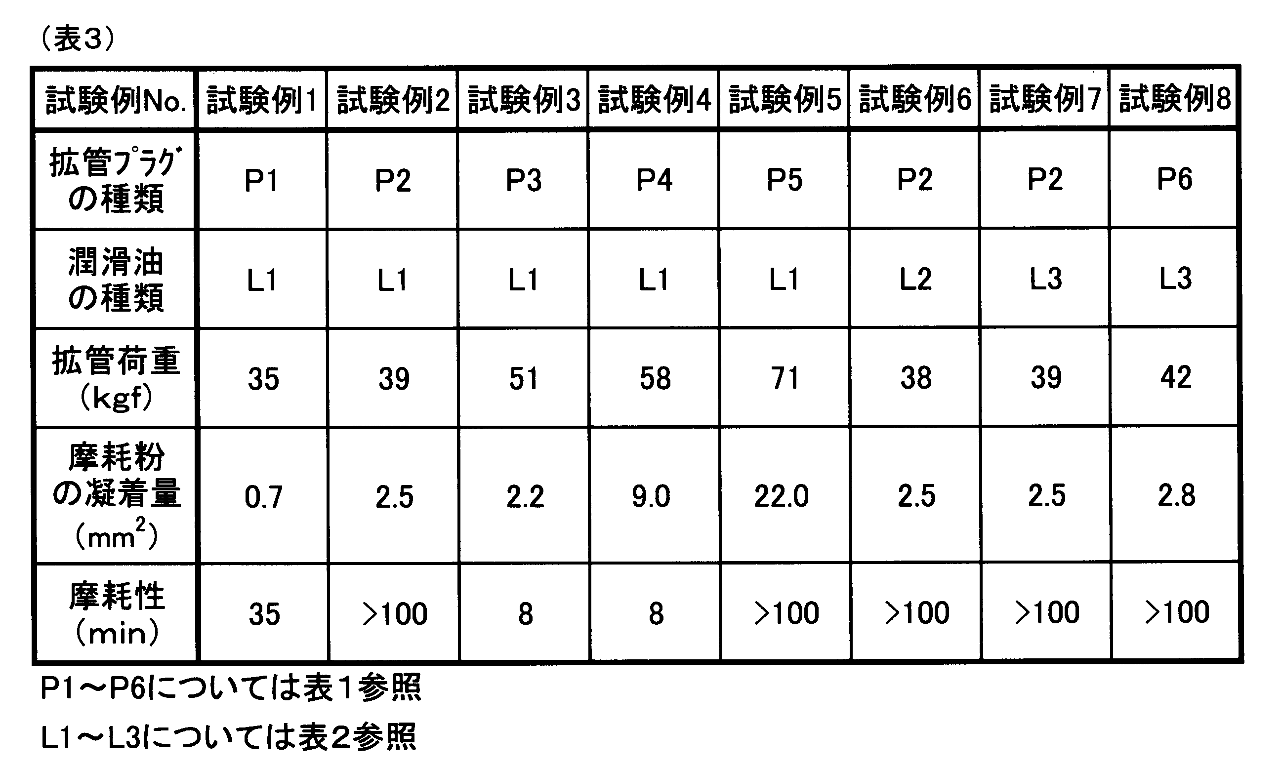
表1~表3より知られるごとく、下地層を有し、その上にAH/ACが平均で0.03以上かつ0.15以下であり、PIG/PIDが3未満であるDLC膜が形成された拡管プラグ(試料P2、試料P6)を用いると、少量の潤滑油でも拡管荷重を充分かつ確実に小さくすることができると共に、金属摩耗粉の凝着を充分かつ確実に抑制することができる(試験例2、試験例6,試験例7、及び試験例8参照)。また、上記特定のDLC膜は耐摩耗性に優れているため、このようなDLC膜が形成された拡管プラグ(試料P2、試料P6)は、耐久性に優れる。なお、試料P2及び試料P6が実施例にかかる拡管プラグであり、その他の試料は比較例にかかる拡管プラグである。また、試験例2、試験例6,試験例7、及び試験例8が実施例にかかる拡管方法であり、その他の試験例は比較例にかかる拡管方法である。
Claims (8)
- 金属管内に該金属管の内径よりも大きな外径を有する拡管プラグを強制的に挿入して上記金属管の外径を拡張させるために用いられる拡管プラグであって、
該拡管プラグは、プラグ本体部と、該プラグ本体部の表面に被覆された下地層と、該下地層上に被覆されたダイヤモンドライクカーボン膜とを有し、
上記下地層は、Si、Ti、Zr、V、Nb、Ta、Cr、Mo、Wから選ばれる1種または2種以上からなり、
上記ダイヤモンドライクカーボン膜中の水素原子数の割合AH(atm%)と炭素原子数の割合AC(atm%)との比AH/ACが、平均で0.03以上かつ0.15以下であり、
上記ダイヤモンドライクカーボン膜のラマンスペクトルにおけるGバンドのピーク強度PIGとDバンドのピーク強度PIDとの比PIG/PIDが3未満であることを特徴とする拡管プラグ。 - 上記ダイヤモンドライクカーボン膜中の上記水素原子数の割合及び上記炭素原子数の割合は、上記ダイヤモンドライクカーボン膜のグロー放電発光分光分析により測定された値であることを特徴とする請求項1に記載の拡管プラグ。
- 板状の基材上に形成したダイヤモンドライクカーボン膜に、2μlのイソパラフィン又はα-オレフィンを滴下してから上記イソパラフィン又は上記α-オレフィンが直径15mmに広がるまでに要する時間が80秒以内となる膜が上記拡管プラグ用の上記ダイヤモンドライクカーボン膜として用いられていることを特徴とする請求項1又は2に記載の拡管プラグ。
- 上記金属管は、アルミニウム管又はアルミニウム合金管であることを特徴とする請求項1~3のいずれか1項に記載の拡管プラグ。
- 温度40℃における動粘度が0.5~20cStである潤滑油を上記金属管の少なくとも内周面に存在させた状態で用いられることを特徴とする請求項1~4のいずれか1項に記載の拡管プラグ。
- プレート状のフィン材に設けた貫通穴内に配置した冷媒配管用の上記金属管内に挿入するために用いられることを特徴とする請求項1~5のいずれか1項に記載の拡管プラグ。
- 金属管内に請求項1~6のいずれか1項に記載の拡管プラグを強制的に挿入して上記金属管の外径を拡張させる金属管の拡管方法であって、
上記金属管と上記拡管プラグとの間に、温度40℃における動粘度が0.5~20cStである潤滑油を存在させた状態で上記金属管の拡管を行うことを特徴とする金属管の拡管方法。 - 上記潤滑油の主成分は、イソパラフィン又はα-オレフィンであることを特徴とする請求項7に記載の金属管の拡管方法。
Priority Applications (2)
| Application Number | Priority Date | Filing Date | Title |
|---|---|---|---|
| JP2014547060A JP6604701B2 (ja) | 2012-11-19 | 2013-11-18 | 拡管プラグ及び金属管の拡管方法 |
| CN201380060220.7A CN104797356B (zh) | 2012-11-19 | 2013-11-18 | 扩管插塞及金属管的扩管方法 |
Applications Claiming Priority (2)
| Application Number | Priority Date | Filing Date | Title |
|---|---|---|---|
| JP2012252895 | 2012-11-19 | ||
| JP2012-252895 | 2012-11-19 |
Publications (1)
| Publication Number | Publication Date |
|---|---|
| WO2014077382A1 true WO2014077382A1 (ja) | 2014-05-22 |
Family
ID=50731290
Family Applications (1)
| Application Number | Title | Priority Date | Filing Date |
|---|---|---|---|
| PCT/JP2013/081009 Ceased WO2014077382A1 (ja) | 2012-11-19 | 2013-11-18 | 拡管プラグ及び金属管の拡管方法 |
Country Status (3)
| Country | Link |
|---|---|
| JP (1) | JP6604701B2 (ja) |
| CN (1) | CN104797356B (ja) |
| WO (1) | WO2014077382A1 (ja) |
Cited By (1)
| Publication number | Priority date | Publication date | Assignee | Title |
|---|---|---|---|---|
| JP2017101866A (ja) * | 2015-12-01 | 2017-06-08 | 株式会社デンソー | 熱交換器およびその製造方法 |
Families Citing this family (3)
| Publication number | Priority date | Publication date | Assignee | Title |
|---|---|---|---|---|
| CN109764195A (zh) * | 2017-11-10 | 2019-05-17 | 株式会社涂料韩国 | 具有插口的金属管、金属管的连接装置及制造方法 |
| EP3875182A4 (en) * | 2018-10-31 | 2022-11-23 | Toyo Seikan Group Holdings, Ltd. | PROCESSING JIG AND METHOD FOR PRODUCTION OF SEAMLESS CAN BODY |
| EP4574297A4 (en) | 2022-09-16 | 2025-12-17 | Daikin Ind Ltd | HEAT EXCHANGER MANUFACTURING PROCESS |
Citations (2)
| Publication number | Priority date | Publication date | Assignee | Title |
|---|---|---|---|---|
| JP2008093713A (ja) * | 2006-10-13 | 2008-04-24 | Sumitomo Light Metal Ind Ltd | 金属管の拡管方法、それに用いる拡管冶具、及びそれに用いる潤滑油 |
| JP2009241252A (ja) * | 2007-06-01 | 2009-10-22 | Toyohashi Univ Of Technology | Dlc被覆工具 |
Family Cites Families (7)
| Publication number | Priority date | Publication date | Assignee | Title |
|---|---|---|---|---|
| DE3030231A1 (de) * | 1980-08-09 | 1982-02-18 | Rohde & Schwarz GmbH & Co KG, 8000 München | Stanzwerkzeug |
| CN1131990C (zh) * | 1998-07-22 | 2003-12-24 | 汉斯·京特纳有限公司 | 换热器装置和装配该换热器装置的方法 |
| JP2003010928A (ja) * | 2001-06-26 | 2003-01-15 | Kawasaki Steel Corp | プレス成形用金型およびそれを用いたプレス成形方法 |
| JP4085699B2 (ja) * | 2002-06-04 | 2008-05-14 | トヨタ自動車株式会社 | 摺動部材及びその製造方法 |
| JP4341572B2 (ja) * | 2005-03-29 | 2009-10-07 | ブラザー工業株式会社 | ポンチ及びインクジェットヘッドのノズル形成用ポンチ |
| JP4644072B2 (ja) * | 2005-09-02 | 2011-03-02 | 株式会社スギノマシン | 拡管工具 |
| JP2006209965A (ja) * | 2006-03-28 | 2006-08-10 | Hoya Corp | 磁気ディスクの製造方法 |
-
2013
- 2013-11-18 CN CN201380060220.7A patent/CN104797356B/zh not_active Expired - Fee Related
- 2013-11-18 WO PCT/JP2013/081009 patent/WO2014077382A1/ja not_active Ceased
- 2013-11-18 JP JP2014547060A patent/JP6604701B2/ja active Active
Patent Citations (2)
| Publication number | Priority date | Publication date | Assignee | Title |
|---|---|---|---|---|
| JP2008093713A (ja) * | 2006-10-13 | 2008-04-24 | Sumitomo Light Metal Ind Ltd | 金属管の拡管方法、それに用いる拡管冶具、及びそれに用いる潤滑油 |
| JP2009241252A (ja) * | 2007-06-01 | 2009-10-22 | Toyohashi Univ Of Technology | Dlc被覆工具 |
Cited By (1)
| Publication number | Priority date | Publication date | Assignee | Title |
|---|---|---|---|---|
| JP2017101866A (ja) * | 2015-12-01 | 2017-06-08 | 株式会社デンソー | 熱交換器およびその製造方法 |
Also Published As
| Publication number | Publication date |
|---|---|
| CN104797356A (zh) | 2015-07-22 |
| JP6604701B2 (ja) | 2019-11-13 |
| JPWO2014077382A1 (ja) | 2017-01-05 |
| CN104797356B (zh) | 2017-10-03 |
Similar Documents
| Publication | Publication Date | Title |
|---|---|---|
| Bhowmick et al. | High temperature tribological behavior of tetrahedral amorphous carbon (ta-C) and fluorinated ta-C coatings against aluminum alloys | |
| JP6604701B2 (ja) | 拡管プラグ及び金属管の拡管方法 | |
| CN101341274B (zh) | 非晶质硬质碳被膜 | |
| CN106661717B (zh) | 被覆滑动构件 | |
| JP6337944B2 (ja) | 被覆工具 | |
| JP2008297477A (ja) | 低摩擦摺動部材 | |
| Mobarak et al. | Tribological properties of amorphous hydrogenated (aC: H) and hydrogen-free tetrahedral (ta-C) diamond-like carbon coatings under jatropha biodegradable lubricating oil at different temperatures | |
| Sung | Tribological characteristics of various surface coatings for rotary compressor vane | |
| Tyagi et al. | Wettability and performance of Cu-MoS2/SiC coating prepared by electro-discharge coating process | |
| WO2013129320A1 (ja) | 被覆回転ツールおよびその製造方法 | |
| WO2013129321A1 (ja) | 被覆回転ツールおよびその製造方法 | |
| Bhowmick et al. | Tribological behaviour of W-DLC against an aluminium alloy subjected to lubricated sliding | |
| JP5150861B2 (ja) | 硬質炭素膜およびその形成方法 | |
| Murakawa et al. | Tribological behavior of amorphous hard carbon films against zinc-plated steel sheets | |
| Dosbaeva et al. | Enhancement of wet-and MQL-based machining of automotive alloys using cutting tools with DLC/polymer surface treatments | |
| JP3872385B2 (ja) | 溝付きプラグ | |
| JP5207116B2 (ja) | 潤滑特性に優れた硬質皮膜および、金属塑性加工用工具 | |
| Giagkas et al. | Tribological properties of ZrN coatings deposited by magnetron sputtering in reactive and non-reactive mode | |
| JP4380377B2 (ja) | カーボン系膜形成方法 | |
| Dohda et al. | Evaluation of tribo-characteristics of diamond-like-carbon containing Si by metal forming simulators | |
| JP2012161853A (ja) | 切削工具 | |
| Cursaru et al. | Improvement of Antiwear Properties by Coating the Steel Surfaces and by Lubricant Additivation | |
| JP7731532B2 (ja) | 硬質炭素膜とその成膜方法 | |
| Kumagai et al. | Tribological properties of hybrid process DLC coating against magnesium alloy | |
| US20240327975A1 (en) | Tribological composites |
Legal Events
| Date | Code | Title | Description |
|---|---|---|---|
| 121 | Ep: the epo has been informed by wipo that ep was designated in this application |
Ref document number: 13854328 Country of ref document: EP Kind code of ref document: A1 |
|
| ENP | Entry into the national phase |
Ref document number: 2014547060 Country of ref document: JP Kind code of ref document: A |
|
| NENP | Non-entry into the national phase |
Ref country code: DE |
|
| 122 | Ep: pct application non-entry in european phase |
Ref document number: 13854328 Country of ref document: EP Kind code of ref document: A1 |